
Characterization of high-velocity impact damage in … · 3 Bunkyo-cho, Matsuyama, Ehime 790-8577,...
31
1 2 3 4 5 6 7 8 9 10 11 12 13 14 15 16 17 18 19 20 21 22 23 24 25 26 27 28 29 30 31 32 33 34 35 36 37 38 39 40 41 42 43 44 45 46 47 48 49 50 51 52 53 54 55 56 57 58 59 60 61 62 63 64 65 1 Characterization of high-velocity impact damage in CFRP laminates: Part I– experiment Shigeki Yashiro a,* , Keiji Ogi b , Tsukasa Nakamura c , and Akinori Yoshimura d a Department of Mechanical Engineering, Shizuoka University 3-5-1 Johoku, Naka-ku, Hamamatsu 432-8561, Japan b Graduate School of Science and Engineering, Ehime University 3 Bunkyo-cho, Matsuyama, Ehime 790-8577, Japan c Graduate School of Science and Engineering, Ehime University (Currently, NIPPI Corporation) 3 Bunkyo-cho, Matsuyama, Ehime 790-8577, Japan d Advanced Composite Research Center, Japan Aerospace Exploration Agency (JAXA) 6-13-1, Osawa, Mitaka, Tokyo 181-0015, Japan * Corresponding author: Tel: +81-53-478-1026; Fax: +81-53-478-1026. E-mail address: [email protected] (S. Yashiro) Abstract This study investigated mechanisms of the extension of high-velocity impact damage in CFRP laminates. To this end, damage states due to near-perforation impact were studied in detail. This study consists of two parts. Part I presents the experiment results of high-velocity impact tests for CFRPs with specified stacking sequences. A crater and splits were observed on the impacted surface, while multiple splits with fiber breaks extended on the back surface. The cross-section beneath the impact point included catastrophic ply failure with extensive fiber breaks. Impacted specimens also exhibited a particular delamination pattern consisting *Manuscript Click here to view linked References This document is provided by JAXA.
Transcript of Characterization of high-velocity impact damage in … · 3 Bunkyo-cho, Matsuyama, Ehime 790-8577,...

1 2 3 4 5 6 7 8 9 10 11 12 13 14 15 16 17 18 19 20 21 22 23 24 25 26 27 28 29 30 31 32 33 34 35 36 37 38 39 40 41 42 43 44 45 46 47 48 49 50 51 52 53 54 55 56 57 58 59 60 61 62 63 64 65
1
Characterization of high-velocity impact damage in CFRP laminates: Part I–
experiment
Shigeki Yashiro a,*
, Keiji Ogi b
, Tsukasa Nakamura c, and Akinori Yoshimura
d
a Department of Mechanical Engineering, Shizuoka University
3-5-1 Johoku, Naka-ku, Hamamatsu 432-8561, Japan
b Graduate School of Science and Engineering, Ehime University
3 Bunkyo-cho, Matsuyama, Ehime 790-8577, Japan
c Graduate School of Science and Engineering, Ehime University (Currently, NIPPI
Corporation)
3 Bunkyo-cho, Matsuyama, Ehime 790-8577, Japan
d Advanced Composite Research Center, Japan Aerospace Exploration Agency (JAXA)
6-13-1, Osawa, Mitaka, Tokyo 181-0015, Japan
* Corresponding author: Tel: +81-53-478-1026; Fax: +81-53-478-1026.
E-mail address: [email protected] (S. Yashiro)
Abstract
This study investigated mechanisms of the extension of high-velocity impact damage in
CFRP laminates. To this end, damage states due to near-perforation impact were studied in
detail. This study consists of two parts. Part I presents the experiment results of high-velocity
impact tests for CFRPs with specified stacking sequences. A crater and splits were observed
on the impacted surface, while multiple splits with fiber breaks extended on the back surface.
The cross-section beneath the impact point included catastrophic ply failure with extensive
fiber breaks. Impacted specimens also exhibited a particular delamination pattern consisting
*ManuscriptClick here to view linked References
This document is provided by JAXA.
1 2 3 4 5 6 7 8 9 10 11 12 13 14 15 16 17 18 19 20 21 22 23 24 25 26 27 28 29 30 31 32 33 34 35 36 37 38 39 40 41 42 43 44 45 46 47 48 49 50 51 52 53 54 55 56 57 58 59 60 61 62 63 64 65
2
of pairs of symmetric fan-shaped delaminations emanating from to the impact point and
elongated delamination along the cracks in the bottom ply. These damage patterns were
common to all of the stacking sequences. Part II of this study presents a numerical analysis of
high-velocity impact based on smoothed-particle hydrodynamics and discusses damage
extension mechanisms.
Keywords: A. Polymer-matrix composites (PMCs); B. Impact behaviour; B. Delamination; D:
Fractography.
1. Introduction
Advanced composite materials such as carbon fiber reinforced plastics (CFRPs) have been
frequently used in various industries because of their superior specific strength and specific
stiffness. For example, CFRPs have been applied to primary load-bearing structures like the
fuselage and wings in the latest airplanes. In recent years, CFRPs have also been used in
turbofan engines. One problem with these engines is failure of the engine system caused by
high-velocity impact of foreign objects such as small stones and birds. When a fan blade
breaks and flies apart, the fan case should bear the impact of the fan blade. Therefore,
understanding the mechanisms of foreign object damage in composite materials is essential
for improving the tolerance and reliability against impact at a velocity near the speed of sound
in air.
Delaminations are frequently generated in composite laminates due to out-of-plane impacts,
and many experiments and analytical studies on low-velocity impact damage [1-4] have been
conducted assuming tool drops. Some studies have also been reported on high-velocity
impacts on composite materials. Cantwell and Morton [5-7] investigated the low and high
velocity impact response of CFRP laminates. A series of experiments revealed that the
This document is provided by JAXA.

1 2 3 4 5 6 7 8 9 10 11 12 13 14 15 16 17 18 19 20 21 22 23 24 25 26 27 28 29 30 31 32 33 34 35 36 37 38 39 40 41 42 43 44 45 46 47 48 49 50 51 52 53 54 55 56 57 58 59 60 61 62 63 64 65
3
projectile generated a localized deformation state under high-velocity impact loading, which
was opposite of the low-velocity cases. They also demonstrated that fast-moving projectiles
induced a localized target response and most of the incident energy was then dissipated over a
small area adjacent to the impact point; therefore, for a given impact energy, decreasing
projectile mass (increasing impact velocity) resulted in greater levels of damage. A conical-
shaped shear-out fracture zone was observed in the cross-sections regardless of the stacking
sequence, and a simple perforation model to predict the perforation threshold energy was
developed and verified.
Recent experiment studies [8-13] mainly discussed the energy required for perforation and
energy absorption due to damage extension. López-Puente et al. [8] investigated the
delamination area and its temperature dependence in woven CFRP laminates and quasi-
isotropic CFRP laminates. They demonstrated that the delamination area was constant over a
large velocity range. Tanabe et al. [9] studied laminates made of different reinforcing fibers
and concluded that the mechanical properties of the rear layer play an important role for
energy absorption and that a laminate with lower interlaminar shear strength effectively
absorbed the impact energy. Hazell et al. [10,11] investigated the influence of the impact
velocity and determined that the energy absorption accompanied by damage extension was
constant for high- to hyper-velocity impacts. Appleby-Thomas et al. [12] carried out ice
impact tests with CFRPs assuming a hail storm and studied the projected damage area and the
CAI strength. Shimamoto et al. [13] studied impact response at cryogenic temperatures and
concluded that the stacking sequence played an important role to control the damaged region
of a main space structure. Furthermore, the recent advances in experimental studies on high-
velocity impacts of composite materials have been summarized in the latest reviews [14,15].
Wen [16] and López-Puente et al. [17] proposed theories to predict the ballistic limit velocity
This document is provided by JAXA.

1 2 3 4 5 6 7 8 9 10 11 12 13 14 15 16 17 18 19 20 21 22 23 24 25 26 27 28 29 30 31 32 33 34 35 36 37 38 39 40 41 42 43 44 45 46 47 48 49 50 51 52 53 54 55 56 57 58 59 60 61 62 63 64 65
4
by considering the energy balance and the energy dissipation due to damage extension. These
theories were compared with experiment results and were verified [16-18]. Numerical studies
using finite-element analysis on the impact response of composite plates have also been
reported. Gower et al. [19] analyzed the ballistic impact of an AFRP laminate and obtained
reasonable agreement with the experiment results for back-surface displacement and
delamination. He et al. [20] used only a projectile model to predict the penetration depth and
the ballistic limit, assuming that the response of the target was a function of the impact
velocity. López-Puente et al. [21] successfully predicted the projected damage area in CFRP
woven laminates due to normal and oblique ballistic impacts.
The extension mechanisms of complex impact damage in composite laminates must be
understood to improve the reliability of composite structures, because such impact damage
severely degrades residual strength. However, the final goal of the studies on high-velocity
impact response of composite materials is applications such as space debris bumper shields
and armor, so previous studies on high-velocity and hyper-velocity impacts (e.g., Refs.
[22,23]) focused on the perforation and the ballistic limit, and there have been few detailed
discussions of the various kinds of damage in plies and at ply interfaces. Characterization of
the extension of high-velocity impact damage is valuable for clarifying the energy absorption
mechanisms and eventually the ballistic limit.
This study therefore sought to characterize high-velocity impact damage in CFRP laminates
and to clarify its extension mechanism. To this end, we focus on damage states caused by
near-perforation impacts. This study consists of two parts. Part I conducts high-velocity
impact tests on CFRP laminates with four basic stacking sequences, namely a unidirectional
laminate, two cross-ply laminates, and a quasi-isotropic laminate, and presents detailed
observations of the resulting impact damage using optical microscopy and soft X-ray
This document is provided by JAXA.

1 2 3 4 5 6 7 8 9 10 11 12 13 14 15 16 17 18 19 20 21 22 23 24 25 26 27 28 29 30 31 32 33 34 35 36 37 38 39 40 41 42 43 44 45 46 47 48 49 50 51 52 53 54 55 56 57 58 59 60 61 62 63 64 65
5
radiography. Part II will analyze the extension of impact damage in CFRP laminates based on
smoothed-particle hydrodynamics (SPH) and will discuss the mechanism of damage
extension.
2. Materials and procedure
Carbon-fiber-reinforced epoxy prepreg sheets (T700S/#2521R, Toray Industries) were used,
and the laminates were manufactured by heating and pressing the stacked sheets in a vacuum
chamber. The stacking sequences were unidirectional [016] (UD), cross-ply [04/904]S (CP1),
cross-ply [0/90]4S (CP2), and quasi-isotropic [0/45/90/-45]S2 (QI). The fiber direction in the
top and bottom plies was defined as the 0° direction. The prepared laminates were cut into
square specimens 55 mm on a side and 1.6 mm thick. Although the size of the target may be
small, the areal dimensions could have little influence on the high-velocity impact response,
and small-scale specimens were sufficient to reproduce the damage states in large structures
[24]. The specimen thickness may also be small for typical applications, but thin specimens
were employed to discuss near-perforation damage using our impact testing machine.
Figure 1 schematically depicts a high-velocity impact testing machine (Maruwa Electronic
Incorporated). This machine consists of a control unit for the power source, a chamber in
which a projectile was shot at a target, and a speed detector with a data logger. The projectile,
set in a sabot, was accelerated with high-temperature, high-pressure metal plasma obtained by
melting and evaporating an aluminum foil subjected to high-voltage pulse current. The sabot
was stopped at the mouth of the gun, and the sphere moved ahead by inertia. The velocity of
the projectile was variable from 40 to 1500 m/s. The velocity was controlled by the voltage
applied to the aluminum foil and was precisely measured by obtaining the time required for
the projectile to pass the prescribed distance (250 mm) in the speed detector. Only the four
This document is provided by JAXA.

1 2 3 4 5 6 7 8 9 10 11 12 13 14 15 16 17 18 19 20 21 22 23 24 25 26 27 28 29 30 31 32 33 34 35 36 37 38 39 40 41 42 43 44 45 46 47 48 49 50 51 52 53 54 55 56 57 58 59 60 61 62 63 64 65
6
edges of the specimen were fixed to a square-frame jig, and therefore bending due to impact
was permitted. The projectile was a steel ball 1.5 mm in diameter (14.2 mg in mass), and the
impact velocity was 300 to 1200 m/s. The tests were conducted in an atmospheric
environment.
After the test, the damage patterns on the front and back surfaces of the specimen were
observed by a stereomicroscope. The specimen was then cut and polished to facilitate
observing the damage beneath the impact point by an optical microscope. Internal damage in
some specimens was nondestructively imaged by soft X-ray radiography.
3. Experiment results
3.1 Impact damage on the front and back surfaces
Figures 2-5 depict the damage patterns on the front surface and the back surface at
specified impact velocities. None of the specimens were penetrated by the projectile, despite
severe damage on the back surfaces. The front surfaces of all of the specimens had a crater
with splits extending from the crater edges. This damage pattern appeared regardless of the
stacking sequence and the impact velocity. The back surfaces had fiber breaks due to the
indentation of the projectile and the accompanying splits; this pattern was observed in all four
stacking sequences. Splits on the back surface in the UD laminate were generated at a lower
velocity (437 m/s) than in the other laminates because of its low bending stiffness in the
transverse direction. The fiber breaks on the back surface exhibited the zigzag pull-out
patterns that can be seen on tensile fracture surfaces, so it was determined that the bending-
induced tensile stress along the fiber direction caused fiber breaks on the back surface.
In order to quantitatively evaluate the influence of the stacking sequence on the external
damage, the projected damage area on the surfaces was measured by imaging software; on the
This document is provided by JAXA.
1 2 3 4 5 6 7 8 9 10 11 12 13 14 15 16 17 18 19 20 21 22 23 24 25 26 27 28 29 30 31 32 33 34 35 36 37 38 39 40 41 42 43 44 45 46 47 48 49 50 51 52 53 54 55 56 57 58 59 60 61 62 63 64 65
7
back surface, the damaged region was approximated by several rectangular shapes instead of
the projection because of the large out-of-plane deformation. Figure 6 plots the projected
damage area against the impact velocity. The damage area on the front surface increased with
increasing velocity. This trend was most prominent in the QI laminate, followed by the CP1
and CP2 laminates. However, in the UD laminate, the projected damage area was almost
constant (5 mm2) when plotted against the impact velocity. The damage area on the back
surface increased with increasing impact velocity in all the laminates. This increasing trend
was significant in the QI and CP2 laminates, and the damage area of the CP1 laminate was
always smaller than that of the CP2 laminate. Although the increasing trend also appeared on
the back surface of the UD laminate, the growth rate was less than that of the other laminates.
The damage area on the front and back surfaces will become constant at higher impact
velocities generating a perforation hole [9,25].
The bending stiffness was calculated by classical lamination theory assuming that bending
deformation due to the impact contributes to the damage extension on the back surface,
although the high-velocity impact induces local bending deformation [4,5], and thus a simple
discussion is difficult. Bending stiffness components D11 and D22 are listed in Table 1, where
the longitudinal Young’s modulus is 140 GPa, the transverse Young’s modulus is 10 GPa, the
in-plane Poisson’s ratio is 0.35, and the in-plane shear modulus is 5 GPa. Here, subscripts 1
and 2 represent the longitudinal direction and the transverse direction in the 0° ply. In the UD
and CP1 laminates, the D22 component is much smaller than the D11 component, and the
curvature in the transverse direction of the 0° ply is larger than that in the longitudinal
direction. Combined with the anisotropy of the strengths, the fiber-break region becomes
small and matrix cracks extend significantly. The above discussion can be confirmed by the
observation of the full cross-sections of these laminates (Fig. 7). In the cross-section normal
This document is provided by JAXA.
1 2 3 4 5 6 7 8 9 10 11 12 13 14 15 16 17 18 19 20 21 22 23 24 25 26 27 28 29 30 31 32 33 34 35 36 37 38 39 40 41 42 43 44 45 46 47 48 49 50 51 52 53 54 55 56 57 58 59 60 61 62 63 64 65
8
to the 0° direction whose top and bottom layers are transverse plies, the small bending
stiffness caused severe local bending deformation, which resulted in extensive matrix cracks
in the bottom layer (Figs. 7a and 7c). However, this deformation of the CP1 laminate was
smaller than that of the UD laminate because of the smaller difference between the D11 and
D22 components. This reduced matrix cracks but induced fiber breaks in the bottom layer (Fig.
7d). The D22 component is much balanced with the D11 component in the CP2 and QI
laminates, and the bending deformation becomes less than that in the transverse direction of
the other two laminates. Many fiber breaks are then generated due to the indentation of the
projectile. Further indentation expands the fiber-break region and peeling off of the bottom
ply, which causes matrix cracks in the back surface. Therefore, the CP2 and QI laminates have
a larger damage area on the back surface than the UD and CP1 laminates because of the
extensive fiber breaks.
3.2 Damage state beneath the impact point
Two cross-sections including the impact point were observed by an optical microscope.
One is a cross-section normal to the fiber direction of the 0° ply (N-section); the other is a
cross-section parallel to that direction (P-section).
Figure 8 depicts the damage state beneath the impact point in the UD laminate. A crater,
delaminations, and oblique matrix cracks appeared in the N-section (Fig. 8a). The region just
beneath the crater broke catastrophically. Oblique matrix cracks (i.e., cone cracks) were
generated outside the catastrophic failure zone and were connected with delamination. In the
bottom ply, a matrix crack connected to the ply failure zone had a large opening distance due
to severe bending deformation. The crater and delaminations were also observed in the P-
section (Fig. 8b). The fibers seemed to be cut by out-of-plane shear deformation at the crater
This document is provided by JAXA.

1 2 3 4 5 6 7 8 9 10 11 12 13 14 15 16 17 18 19 20 21 22 23 24 25 26 27 28 29 30 31 32 33 34 35 36 37 38 39 40 41 42 43 44 45 46 47 48 49 50 51 52 53 54 55 56 57 58 59 60 61 62 63 64 65
9
edge. The P-section delamination had a larger opening displacement than the N-section, and
therefore the delamination extended extensively toward the fiber direction.
Figure 9 depicts the damage state beneath the impact point in the CP1 laminate. A crush
region (i.e., a crater) in the top 0° plies, fiber breaks and delamination in the 90° plies, and
matrix cracks in the bottom 0° plies were observed in the N-section (Fig. 9a). The fiber breaks
and delaminations in the 90° plies induced easy deformation of the bottom 0° plies, and
matrix cracks were then generated in the bottom plies. A crater with fiber breaks, a
catastrophic ply-failure zone, cone cracks, and delaminations were observed in the P-section
(Fig. 9b), where the four bottom 0° plies were delaminated and dropped off. Considering fiber
breaks in 90° plies beneath the impact point in the N-section, the catastrophic ply-failure zone
was found to include extensive fiber breaks, matrix cracking, matrix crushing, and
delaminations. Cone cracks and delaminations outside the catastrophic ply failure zone in the
90° plies were similar to those observed in the N-section of the UD laminate (Fig. 8b).
The damage patterns beneath the impact point in the CP2 laminate are depicted in Fig. 10.
A crater, fiber breaks, matrix cracks (cone cracks), and delaminations were observed in both
the N- and the P-sections. Some matrix cracks were generated in a single ply, with their tips
connected to delamination that occurred only at the 0°/90° (90°/0°) interfaces in the N- (P-)
section. More specifically, the upper (lower) ply of delamination was always the transverse
(longitudinal) ply. This pattern suggested that the delamination extended from a catastrophic
ply failure such as matrix cracking in the transverse ply. Although oblique matrix cracks were
generated in every transverse ply, these cracks did not make straight cone cracks beyond the
longitudinal plies due to the severe delamination.
Figure 11 depicts the P-section including the impact point for the QI laminate, although
both the top and bottom plies had dropped parts. Fiber breaks, delaminations, and matrix
This document is provided by JAXA.

1 2 3 4 5 6 7 8 9 10 11 12 13 14 15 16 17 18 19 20 21 22 23 24 25 26 27 28 29 30 31 32 33 34 35 36 37 38 39 40 41 42 43 44 45 46 47 48 49 50 51 52 53 54 55 56 57 58 59 60 61 62 63 64 65
10
cracks in off-axis plies were observed, and there was no well-defined cone crack because of
extensive delamination. Most of the ply interfaces were delaminated, and the stress
concentration just beneath the impact point was reduced. This dissipated the impact energy
and prevented damage progress in each ply, and thus a small catastrophic ply failure zone was
formed.
3.3 Soft X-ray radiography
Typical soft X-ray photographs of the four laminates are presented in Fig. 12. The UD
laminate exhibited delamination elongated in the fiber direction, while the delamination was
small in the transverse direction. Delaminations observed near the impact point in the CP1
laminate could be separated into two delaminations since there were two ply interfaces. One
was a delamination at the upper 0°/90° ply interface that was connected to the matrix cracks
in the top 0° plies and extended in the transverse direction. The other was a pair of fan-shaped
delaminations along the matrix crack in the bottom 0° plies that were symmetric about the
impact point. Multiple fan-shaped delaminations near the impact point and elongated
delamination accompanied by a matrix crack in the bottom ply were observed in the CP2 and
QI laminates.
The fan-shaped delaminations were symmetric about the impact point in all of the stacking
sequences except for the UD laminate. This delamination pattern was the same as that
observed in the laminates subjected to low-velocity impact [26-28]. The delamination at the
lowest interface extended along the matrix cracks (splits in Figs. 2-5) in the bottom 0° ply.
These results indicate that delamination caused by high-velocity impact consisted of fan-
shaped delaminations covering the region between the matrix cracks in two neighboring plies
and elongated delamination along the matrix cracks in the bottom ply, and that this
This document is provided by JAXA.

1 2 3 4 5 6 7 8 9 10 11 12 13 14 15 16 17 18 19 20 21 22 23 24 25 26 27 28 29 30 31 32 33 34 35 36 37 38 39 40 41 42 43 44 45 46 47 48 49 50 51 52 53 54 55 56 57 58 59 60 61 62 63 64 65
11
delamination pattern was independent of the stacking sequences.
Figure 13 plots the projected area of the internal damage, mostly delaminations, against the
impact velocity. The delamination area gradually increased with increasing velocity (< 350
m/s) and steeply increased at a velocity within 350-500 m/s. Small but visible damage (i.e.,
fiber breaks) appeared on the back surface at that velocity range, and this observation
suggested that the impact energy could be dissipated mostly by delamination extension, not
by fiber breaks. The projected delamination area was approximately constant with impact
velocity over 500 m/s (several kJ of impact energy). This trend was observed in all of the
stacking sequences, but the constant values differed among them. This result agreed with the
observations of specimens perforated by high-velocity impact [8,11] and was in contrast to the
low-velocity cases [27,29]. For low-velocity impacts or quasi-static indentations, the energy
of indentation was absorbed by delamination extension caused by global deformation. The
bending deformation was localized by increased impact velocity, and the energy absorption
mechanism then changes from delamination to fiber breaks in the high-strain range [4]. The
trend of a constant delamination area indicates that the impact energy was mainly absorbed by
fiber breaks in the crater and the catastrophic ply-failure zone. This discussion suggests that
the most important parameter governing the ballistic limit is the fiber strength and that
decreased interlaminar toughness may increase the delamination area, the dissipated amount
of the impact energy, and finally the ballistic limit velocity (energy). However, additional tests
and observations are necessary to confirm this.
4. Conclusions
This study carried out high-velocity impact tests for CFRP laminates whose stacking
sequences were unidirectional, two types of cross-ply, and quasi-isotropic. The damage states
This document is provided by JAXA.
1 2 3 4 5 6 7 8 9 10 11 12 13 14 15 16 17 18 19 20 21 22 23 24 25 26 27 28 29 30 31 32 33 34 35 36 37 38 39 40 41 42 43 44 45 46 47 48 49 50 51 52 53 54 55 56 57 58 59 60 61 62 63 64 65
12
near perforation in these laminates were characterized experimentally to understand the
mechanisms of high-velocity impact damage. The conclusions are summarized as follows.
1. The damage patterns on the front and back surfaces were identical among the four
stacking sequences and were independent of the impact velocity. A crater with fiber
breaks and multiple splits at both edges of the crater were generated on the front surface
of the laminates. Multiple matrix cracks extended on the back surface, and fibers broke
just beneath the impact point due to the high impact velocity.
2. The projected surface damage area increased with increasing impact velocity (energy) for
all of the stacking sequences, but the rate of increase differed among them. The damage
area on the back surface could be determined by the bending stiffness. A low bending
stiffness induced a large bending deformation and matrix cracks on the back surface,
which resulted in a small damage area. A high bending stiffness caused many fiber breaks
beneath the impact point due to the localized high strain. These fiber breaks and the
subsequent peeling of the bottom ply resulted in a large damage area.
3. Extensive fiber breaks, which appeared as catastrophic ply failure in the off-axis plies,
were generated beneath the impact point. Outside the ply failure zone, delaminations
extended from the tips of the matrix (cone) cracks.
4. All of the lamination types exhibited a particular delamination pattern consisting of pairs
of fan-shaped delaminations that are symmetrical about the impact point and elongated
delaminations along the matrix cracks in the bottom ply.
Part II of this study presents a damage-extension simulation of high-velocity impacts on
CFRP laminates based on smoothed-particle hydrodynamics (SPH), and the impact response
will be analyzed considering detailed damage modes. The extension mechanisms of the high-
velocity impact damage will be discussed based on these observations.
This document is provided by JAXA.
1 2 3 4 5 6 7 8 9 10 11 12 13 14 15 16 17 18 19 20 21 22 23 24 25 26 27 28 29 30 31 32 33 34 35 36 37 38 39 40 41 42 43 44 45 46 47 48 49 50 51 52 53 54 55 56 57 58 59 60 61 62 63 64 65
13
Acknowledgments
S. Y. acknowledges the support of the Ministry of Education, Culture, Sports, Science and
Technology of Japan under Grants-in-Aid for Scientific Research (Nos. 21360417 and
22760524). The authors would like to express appreciation for technical supports from Mr.
Masamichi Nakata and Mr. Takuya Ioka of Ehime University.
Reference
[1] Richardson MOW, Wisheart MJ. Review of low-velocity impact properties of composite
materials. Compos Part A 1996; 27:1123-1131.
[2] Schoeppner GA, Abrate S. Delamination threshold loads for low velocity impact on
composite laminates. Compos Part A 2000; 31:903-915.
[3] Johnson AF, Pickett AK, Rozycki P. Compoutational methods for predicting impact
damage in composite structures. Compos Sci Technol 2001; 61:2183-2192.
[4] Breen C, Guild F, Pavier M. Impact of thick CFRP laminates: the effect of impact
velocity. Compos Part A 2005; 36:205-211.
[5] Cantwell WJ, Morton J. Comparison of the low and high velocity impact response of
CFRP. Composites 1989; 20:545-551.
[6] Cantwell WJ, Morton J. Impact perforation of carbon fibre reinforced plastic. Compos
Sci Technol 1990; 38:119-141.
[7] Cantwell WJ, Morton J. The influence of varying projectile mass on the impact response
of CFRP. Compos Struct 1989; 13:101-114.
[8] López-Puente J, Zaera R, Navarro C. The effect of low temperatures on the intermediate
and high velocity impact response of CFRPs. Composites Part B 2002; 33:559-566.
This document is provided by JAXA.

1 2 3 4 5 6 7 8 9 10 11 12 13 14 15 16 17 18 19 20 21 22 23 24 25 26 27 28 29 30 31 32 33 34 35 36 37 38 39 40 41 42 43 44 45 46 47 48 49 50 51 52 53 54 55 56 57 58 59 60 61 62 63 64 65
14
[9] Tanabe Y, Aoki M, Fujii K, Kasano H, Yasuda E. Fracture behavior of CFRPs impacted
by relatively high-velocity steel sphere. Int J Impact Eng 2003; 28:627-642.
[10] Hazell PJ, Kister G, Stennett C, Bourque P, Cooper G. Normal and oblique penetration
of woven CFRP laminates by a high velocity steel sphere. Compos Part A 2008; 39:866-
874.
[11] Hazell PJ, Cowie A, Kister G, Stennett C, Cooper GA. Penetration of a woven CFRP
laminate by a high velocity steel sphere impacting at velocities up to 1875 m/s. Int J
Impact Eng 2009; 36:1136-1142.
[12] Appleby-Thomas GJ, Hazell PJ, Dahini G. On the response of two commercially-
important CFRP structures to multiple ice impacts. Compos Struct 2011; 93:2619-2627.
[13] Shimamoto A, Kubota R, Takayama K. High-velocity impact characteristic of carbon
fiber reinforced plastic composite at low temperature. J Strain Analysis 2012; 47:471-
479.
[14] Hazell PJ, Appleby-Thomas GJ. The impact of structural composite materials. Part 1:
ballistic impact. J Strain Analysis 2012; 47:396-405.
[15] Appleby-Thomas GJ, Hazell PJ. The impact of structural composite materials. Part 2:
hypervelocity impact and shock. J Strain Analysis 2012; 47:406-418.
[16] Wen HM. Predicting the penetration and perforation of FRP laminates struck normally
by projectiles with different nose shapes. Compos Struct 2000; 49:321-329.
[17] López-Puente J, Zaera R, Navarro C. An analytical model for high velocity impacts on
thin CFRPs woven laminates plates. Int J Solids Struct 2007; 44:2837-2851.
[18] Caprino G, Lopresto V, Santoro D. Ballistic impact behaviour of stitched graphite/epoxy
laminates. Compos Sci Technol 2007; 67:325-335.
[19] Gower HL, Cronin DS, Plumtree A. Ballistic impact response of laminated composite
This document is provided by JAXA.

1 2 3 4 5 6 7 8 9 10 11 12 13 14 15 16 17 18 19 20 21 22 23 24 25 26 27 28 29 30 31 32 33 34 35 36 37 38 39 40 41 42 43 44 45 46 47 48 49 50 51 52 53 54 55 56 57 58 59 60 61 62 63 64 65
15
panels. Int J Impact Eng 2008; 35:1000-1008.
[20] He T, Wen HM, QIN Y. Finite element analysis to predict penetration and perforation of
thick FRP laminates struck by projectile. Int J Impact Eng 2008; 35:27-36.
[21] López-Puente J, Zaera R, Navarro C. Experimental and numerical analysis of normal
and oblique ballistic impacts on thin carbon/epoxy woven laminates. Compos Part A
2008; 39:374-387.
[22] Tennyson RC, Lamontagne C. Hypervelocity impact damage to composites. Compos
Part A 2000; 31:785-794.
[23] Numata D, Ohtani K, Anyoji M, Takayama K, Togami K, Sun M. HVI tests on CFRP
laminates at low temperature. Int J Impact Eng 2008; 35:1695-1701.
[24] Cantwell WJ. The influence of target geometry on the high velocity impact response of
CFRP. Compos Struct 1988; 10:247-265.
[25] Fujii K, Aoki M, Kiuchi N, Yasuda E, Tanabe Y. Impact perforation behavior of CFRPs
using high-velocity steel sphere. Int J Impact Eng 2002; 27:497-508.
[26] Saito H, Kimpara I. Evaluation of impact damage mechanism of multi-axial stitched
CFRP laminate. Composites Part A 2006; 37:2226-2235.
[27] Hull D, Shi YB. Damage mechanism characterization in composite damage tolerance
investigations. Compos Struct 1993; 23:99-120.
[28] Aymerich F, Meili S. Ultrasonic evaluation of matrix damage in impacted composite
laminates. Compos Part B 2000; 31:1-6.
[29] Nishikawa M, Okabe T, Takeda N. Numerical simulation of interlaminar damage
propagation in CFRP cross-ply laminates under transverse loading. Int J Solids Struct
2007; 44:3101-3113.
This document is provided by JAXA.

1 2 3 4 5 6 7 8 9 10 11 12 13 14 15 16 17 18 19 20 21 22 23 24 25 26 27 28 29 30 31 32 33 34 35 36 37 38 39 40 41 42 43 44 45 46 47 48 49 50 51 52 53 54 55 56 57 58 59 60 61 62 63 64 65
16
Figure and Table captions
Fig. 1 Schematic diagram of the high-velocity impact testing machine with an electric-heat
gun.
Fig. 2 Damage states on the front and back surfaces of the UD [016] laminates.
Fig. 3 Damage states on the front and back surfaces of the CP1 [04/904]S laminates. A barely
visible matrix crack was observed on the back surface at 217 m/s.
Fig. 4 Damage states on the front and back surfaces of the CP2 [0/90]4S laminates. Barely
visible damage appeared on the back surface at 378 m/s.
Fig. 5 Damage states on the front and back surfaces of the QI [0/45/90/-45]S2 laminates.
Barely visible damage appeared on the back surface at 480 m/s.
Fig. 6 Relationship between the projected damage area on the front and back surfaces and the
impact velocity.
Fig. 7 Full cross-sections of the impacted UD and CP1 specimens.
Fig. 8 Damage states beneath the impact point of the UD [016] laminate. Impact velocities
were 760 m/s for the normal cross-section and 530 m/s for the parallel cross-section.
Fig. 9 Damage states beneath the impact point of the CP1 [04/904]S laminate. Impact
velocities were 508 m/s for the normal cross-section and 600 m/s for the parallel cross-
section. The 0° plies on the back surface peeled off due to extensive delamination.
Fig. 10 Damage states beneath the impact point of the CP2 [0/90]4S laminate. Impact
velocities were 500 m/s for the normal cross-section and 700 m/s for the parallel cross-
section.
Fig. 11 Damage states in the parallel cross-section including the impact point of the QI
[0/45/90/-45]S2 laminate. The impact velocity was 707 m/s.
This document is provided by JAXA.

1 2 3 4 5 6 7 8 9 10 11 12 13 14 15 16 17 18 19 20 21 22 23 24 25 26 27 28 29 30 31 32 33 34 35 36 37 38 39 40 41 42 43 44 45 46 47 48 49 50 51 52 53 54 55 56 57 58 59 60 61 62 63 64 65
17
Fig. 12 Soft X-ray photographs of the impacted specimens. Fan-shaped delaminations and
elongated delamination along the matrix cracks in the bottom ply were generated.
Fig. 13 Projected delamintion area of the UD and CP1 laminates against the impact velocity.
Table 1 Bending stiffness calculated using classical lamination theory.
This document is provided by JAXA.

1 2 3 4 5 6 7 8 9 10 11 12 13 14 15 16 17 18 19 20 21 22 23 24 25 26 27 28 29 30 31 32 33 34 35 36 37 38 39 40 41 42 43 44 45 46 47 48 49 50 51 52 53 54 55 56 57 58 59 60 61 62 63 64 65
18
Table 1 Bending stiffness calculated using classical lamination theory.
Stacking configuration D11 (N m) D22 (N m)
UD [016] 48.2 3.4
CP1 [04/904]S 42.6 9.0
CP2 [0/90]4S 30.0 21.6
QI [0/45/90/-45]S2 23.6 18.4
This document is provided by JAXA.

Data logger
Specimen Speed detector
Electric heat gun
Power source control panel Chamber
Fig. 1
Figure(s)
This document is provided by JAXA.

2.5 mm
5 mm
2.5 mm
5 mm 5 mm
2.5 mm
Fig. 2
Front
Back
437 m/s 619 m/s 966 m/s
Crater Splits
Splits
Fiber breaks
0º direction
0º direction
Figure(s)
This document is provided by JAXA.

Fig. 3
5 mm
2.5 mm 2.5 mm
5 mm
2.5 mm
Front
Back
217 m/s 618 m/s 885 m/s
0º direction
2.5 mm 0º direction
Crater Splits
Barely visible matrix crack
This document is provided by JAXA.

2.5 mm 2.5 mm
5 mm 5 mm
2.5 mm
Fig. 4
378 m/s 666 m/s 843 m/s
Front
Back
0º direction
0º direction
Barely visible damage
This document is provided by JAXA.

Barely visible damage
Fig. 5
2.5 mm 2.5 mm
5 mm 5 mm
2.5 mm
867 m/s 559 m/s 480 m/s
Front
Back
0º direction
0º direction
This document is provided by JAXA.
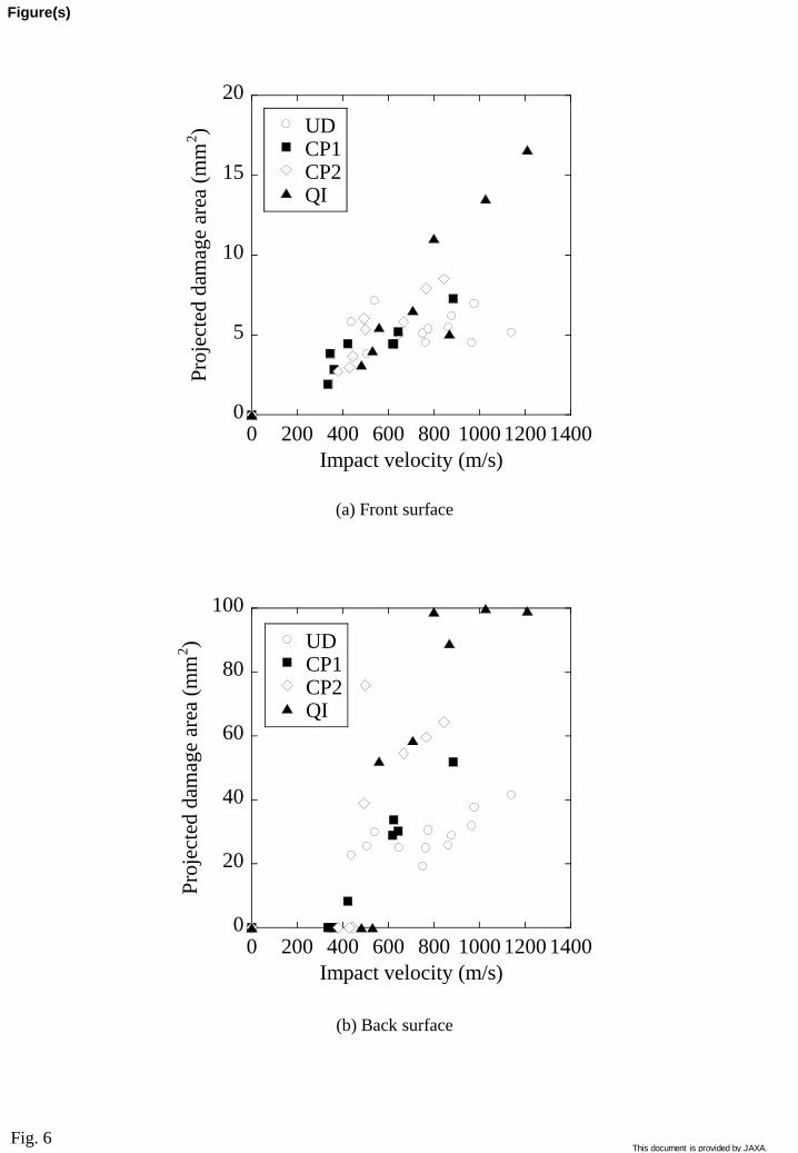
Fig. 6
0
5
10
15
20
0 200 400 600 800 1000 1200 1400
UDCP1CP2QI
Pro
ject
ed d
amag
e ar
ea (
mm
2)
Impact velocity (m/s)
0
20
40
60
80
100
0 200 400 600 800 1000 1200 1400
UDCP1CP2QI
Pro
ject
ed d
amag
e ar
ea (
mm
2)
Impact velocity (m/s)
(a) Front surface
(b) Back surface
Figure(s)
This document is provided by JAXA.
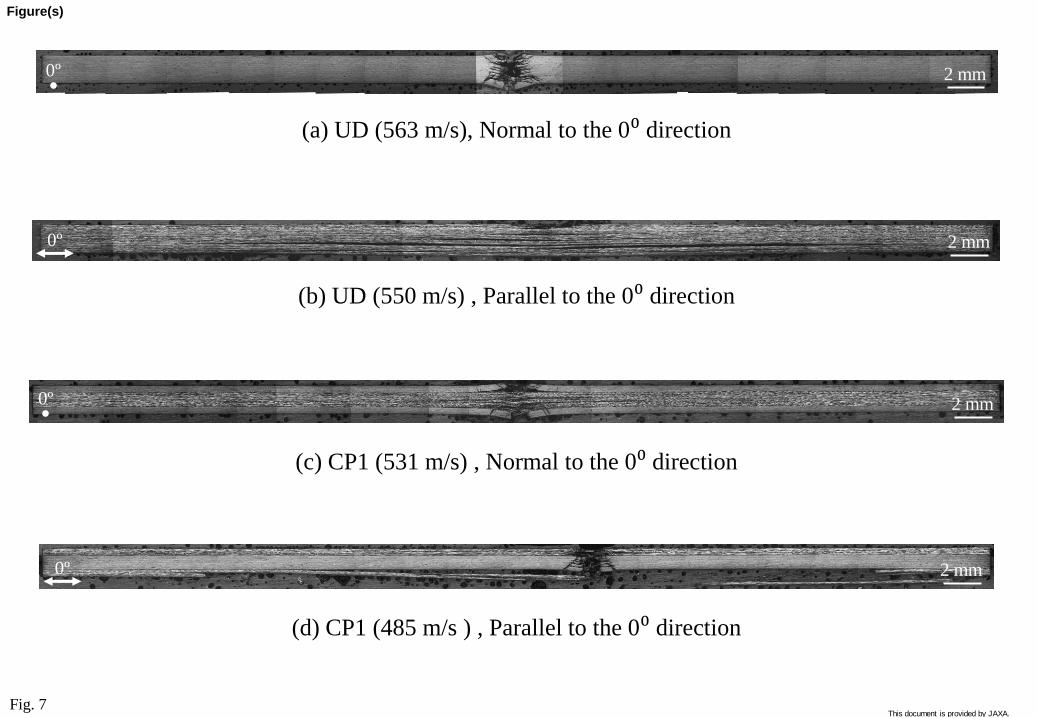
Fig. 7
(a) UD (563 m/s), Normal to the 0⁰ direction
(b) UD (550 m/s) , Parallel to the 0⁰ direction
(c) CP1 (531 m/s) , Normal to the 0⁰ direction
(d) CP1 (485 m/s ) , Parallel to the 0⁰ direction
2 mm
2 mm
0º 2 mm
2 mm 0º
0º
0º
Figure(s)
This document is provided by JAXA.

500 mm
Crater
Delamination
Cone cracks
500 mm
Fiber breaks
Delamination
Crater
(a) Normal cross-section
(b) Parallel cross-section
Fig. 8
Figure(s)
This document is provided by JAXA.

Crater
Delamination
500 mm
500 mm
Crater
Fiber breaks Delamination
Fig. 9
(a) Normal cross-section
(b) Parallel cross-section
Fiber breaks
Cone cracks
Matrix cracks
This document is provided by JAXA.

500 mm
500 mm
Fig. 10
(a) Normal cross-section
(b) Parallel cross-section
Fiber breaks
Crater
Matrix cracks
Delamination
Delamination
Crater Matrix cracks Fiber breaks
This document is provided by JAXA.
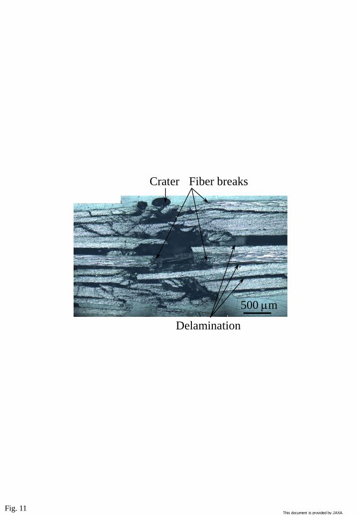
Fig. 11
500 mm
Delamination
Crater Fiber breaks
This document is provided by JAXA.
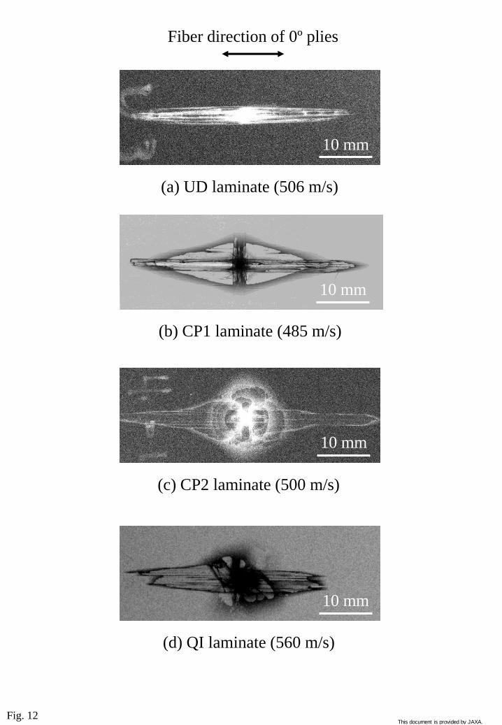
Fig. 12
10 mm
10 mm
(a) UD laminate (506 m/s)
Fiber direction of 0º plies
(b) CP1 laminate (485 m/s)
(c) CP2 laminate (500 m/s)
(d) QI laminate (560 m/s)
10 mm
10 mm
This document is provided by JAXA.

Fig. 13
0
50
100
150
200
250
300
0 200 400 600 800 1000
UDCP1CP2QI
Pro
ject
ed d
elam
inat
ion a
rea
(mm
2)
Impact velocity (m/s)
This document is provided by JAXA.


![Quena Player 14:00 1 4:30 3500B F] tel.0276-57-8577 la - 0284-64 … · 2019. 7. 26. · Quena Player 14:00 1 4:30 3500B F] tel.0276-57-8577 la - 0284-64-9022 info@ren-quena.com QR](https://static.fdocuments.us/doc/165x107/60e1b25b2e78a632ea730dcf/quena-player-1400-1-430-3500b-f-tel0276-57-8577-la-0284-64-2019-7-26.jpg)


![Quena Player 14:00 1 4:30 3500B F] tel.0276-57-8577 la ... · Quena Player 14:00 1 4:30 3500B F] tel.0276-57-8577 la - 0284-64-9022 info@ren-quena.com QR 5 6 7 8 9 10 t) -Sunflower](https://static.fdocuments.us/doc/165x107/5e6fff54864c8f7e28762084/quena-player-1400-1-430-3500b-f-tel0276-57-8577-la-quena-player-1400-1.jpg)
