Paul Lambert (Univ. Stirling) Dave Griffiths (Univ. Stirling)
Upload
elisabeth-mckinneyCategory
view
232download
2
Multi-Focus Range Sensorusing Coded Aperture
Takashi MATSUYAMA
Kyoto Univ.
Shinsaku HIURA
Osaka Univ.
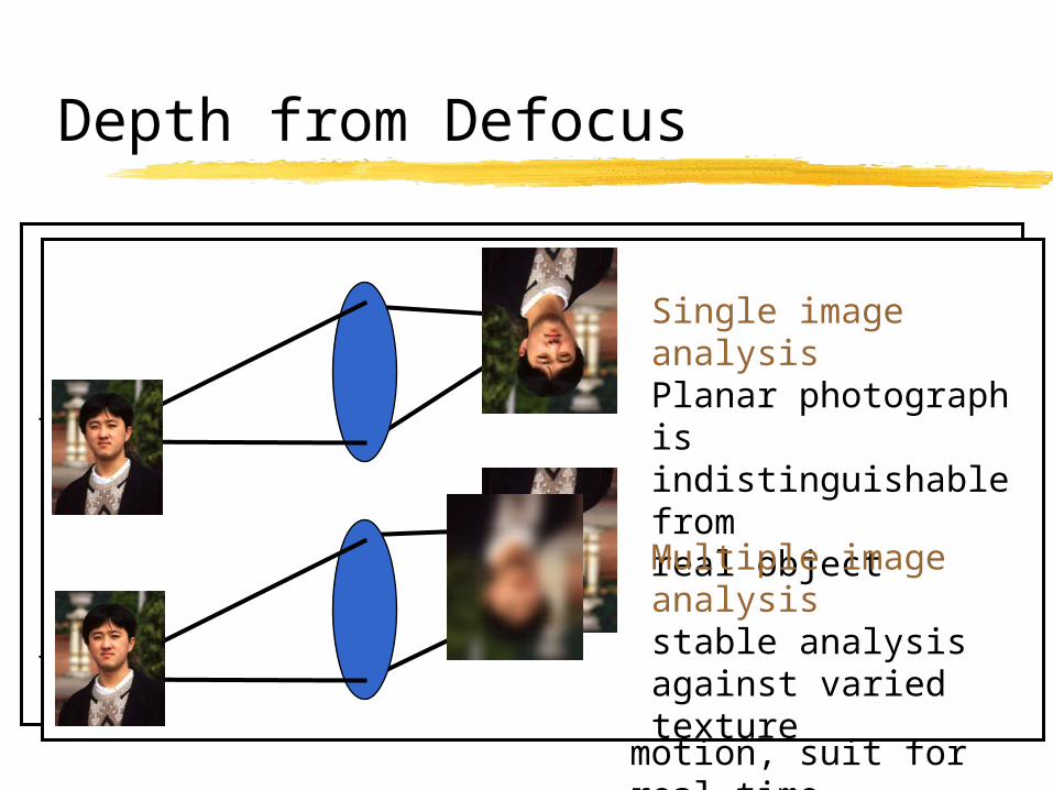
Depth from Defocus
Depth estimation using the quantity of blurring
Passive, and no physical motion - suit for real-time measurement - small and light-weight equipment
Stable depth estimation using relative defocus analysis
small and optimal sensor is necessary
Depth from FocusingSearch focused position by moving lens – not suitable for real-time measurement
Depth from Defocusdistance is estimated from the amount of blurring – no physical motion, suit for real-time measurement
Single image analysisPlanar photograph is indistinguishable fromreal object
Multiple image analysisstable analysis against varied texture

Multi-Focus Camera
Convert color CCD cameraEach CCD is moved 1mm
toward Optical AxisNeutral density by re-
coating the prism surfaceSmall and light as same as
usual color CCD camera

Telecentric Optics
Apreture is set at front focal plane Image size/intensity are equal among each
image plane. Only blurring variesFirst Applying to DFD: Nayar
Usual optics Telecentric optics

Problems of past Depth from Defocus research
High frequency information is lost by Blur(=LPF) unstable range estimation too sensitive to the texture or environment high-quality noiseless image is necessary
Ex. Nayar averages over 256 images to eliminate noise
If the “blur” effect is changed to High-pass or Band-pass filter, it is possible to stabilize range estimation Structured aperture (coded aperture)
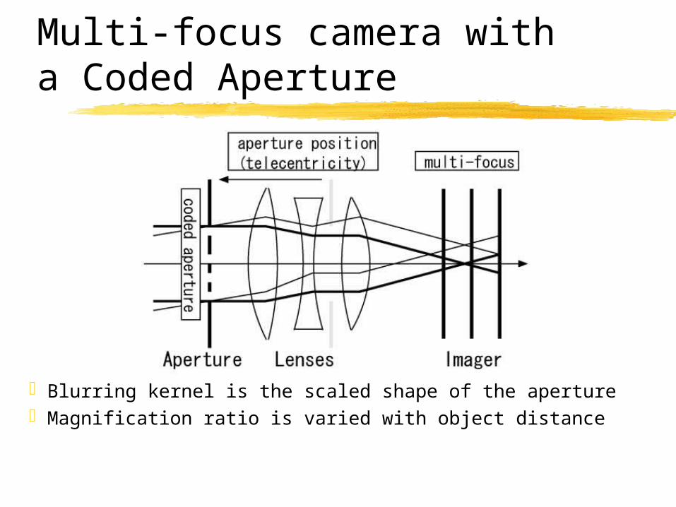
Multi-focus camera witha Coded Aperture
Blurring kernel is the scaled shape of the apertureMagnification ratio is varied with object distance
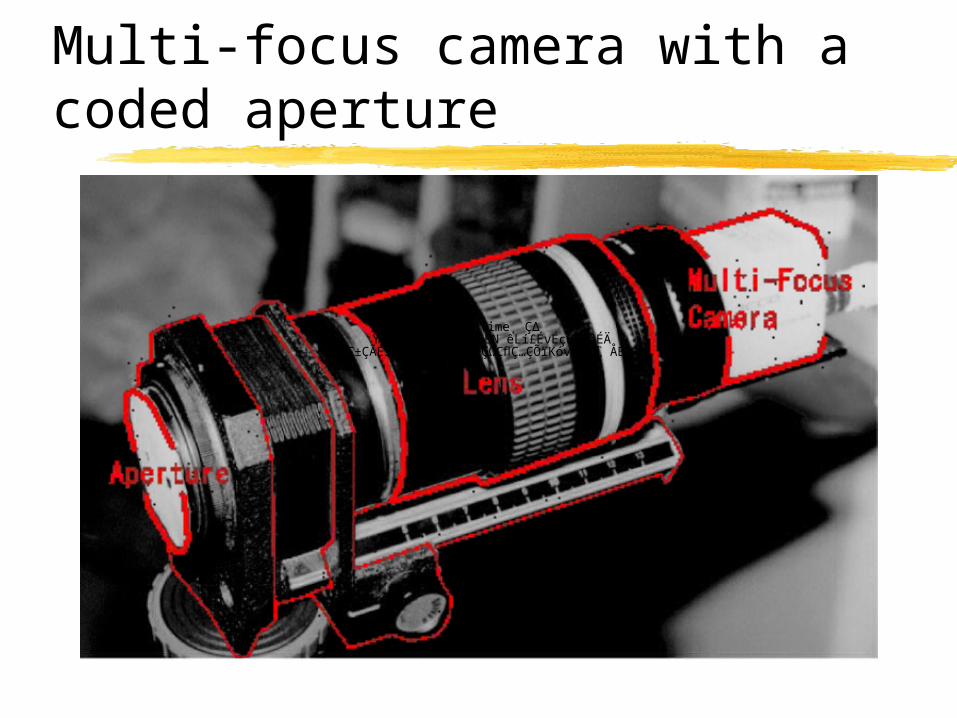
Multi-focus camera with a coded aperture
QuickTime˛ Ç∆YUV420 ÉRÅ[ÉfÉbÉN êLí£ÉvÉçÉOÉâÉÄ
ǙDZÇÃÉsÉNÉ`ÉÉÇ å©ÇÈÇΩÇflÇ…ÇÕïKóvÇ≈Ç∑ÅB

Process of blurring
Blur kernel a(x,y)
convolutionconvolution
convolution
Input image i1(x,y)Input image i2(x,y)
Input image i3(x,y)
Dist. u Focus v
Image s(x,y)
K1 magn.K2 magn
K3 magn.
€
im (x, y) =1
km2 a(
x
km
,y
km
) * s(x, y)
Mathematical model of blurring
f
wvk m
m
−=
Wm: image plane

Range estimaton using FFT
Fourier transform of blurring process
Elimination of original image information
Eval. Func. of range estimation
),(),,(),( qpSvqpAqpI mm ⋅=
),,(
),,(
),(
),(
vqpA
vqpA
qpI
qpI
n
m
n
m =
∑ ∑∀
⎟⎟⎠
⎞⎜⎜⎝
⎛−=
),( ),,(
),,(
),(
),()(
nm s n
m
n
m
vqpA
vqpA
qpI
qpIvr
p, q: spatial freq., v: focus position
Original image info. is eliminated using division
Minimum residual is searched by varying v(focus position). First term is calculated fromtwo input images, and second is from blurring Model.
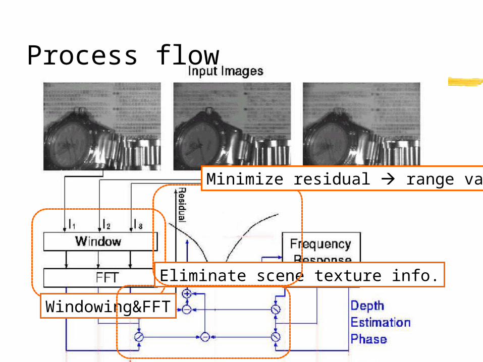
Process flow
Windowing&FFT
Eliminate scene texture info.
Minimize residual range value

Restoration of blur-less image
Inverse filter
High-quality image can be restored, because using multipule images Rich information is remained using coded aperture
∑=
⋅=3
1 ),,(
),(),(
m m
mm vqpA
qpIWqpS
v: focused position Wm: weight calculated from v
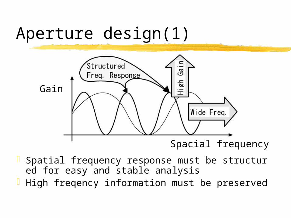
Aperture design(1)
Spatial frequency response must be structured for easy and stable analysis
High freqency information must be preserved
Spacial frequency
Gain

Aperture design(2)
Usual circular aperture is not optimal. This type is suit for beautiful defocused photograph.
Blurring is not observed.
Monotonic, and low gain when blurred.
Feasible, but more peaks are desired.
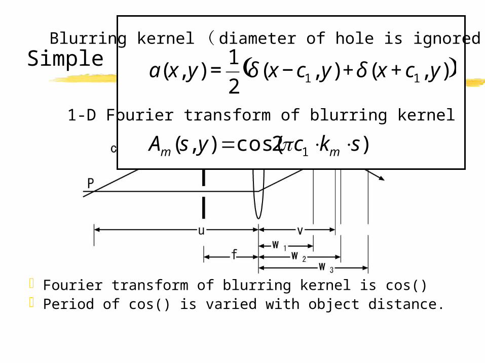
Simple example:2 holes aperture
Fourier transform of blurring kernel is cos()Period of cos() is varied with object distance.
( )),(),(2
1),( 11 ycxycxyxa ++−= δδ
)2cos(),( 1 skcysA mm ⋅⋅= π
Blurring kernel( diameter of hole is ignored)
1-D Fourier transform of blurring kernel

Robustness of range estimation
This “valley shape” shows the ability of robust depth estimation
Residual of evaluation function with varied range

Experiment: input images
First CCDCenter CCD
Last CCD

Restored blur-less image
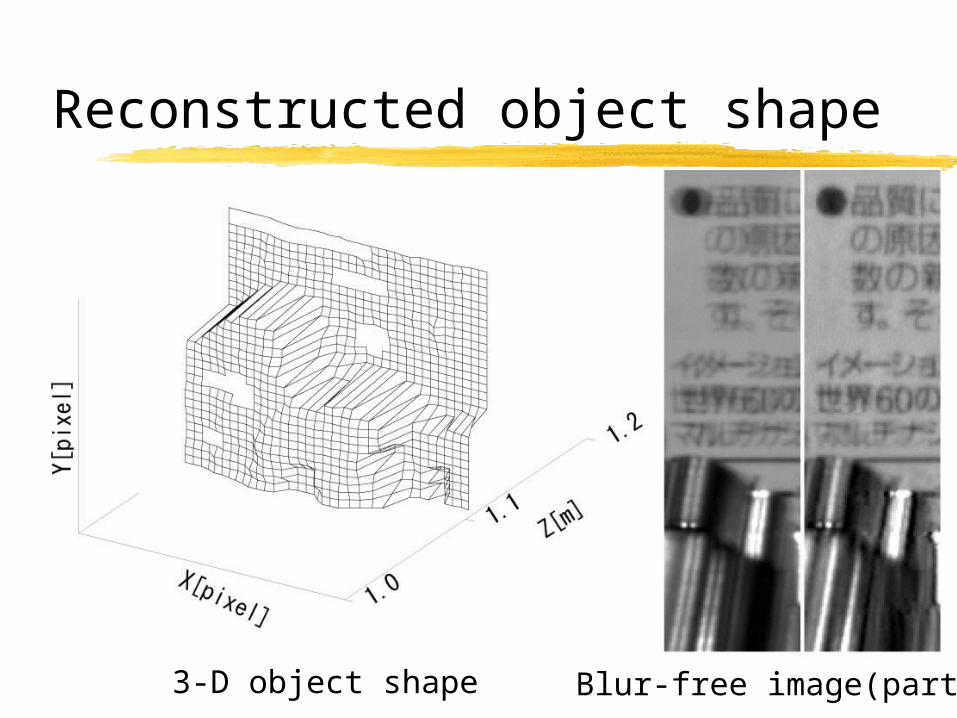
Reconstructed object shape
Blur-free image(partial)3-D object shape

Range analysis using convolution
Blurring kernel is convolved optically
Same convolution is appliedto the opposite image, andwe acquire the same image. ( becase of commutative lawof convolution)
Depth is estimatedby searching theposition that givessame images
Usual circular aperture cannot be used, because twiceblurring gives almost flatimages. Coded apertureenabled such simple principle.
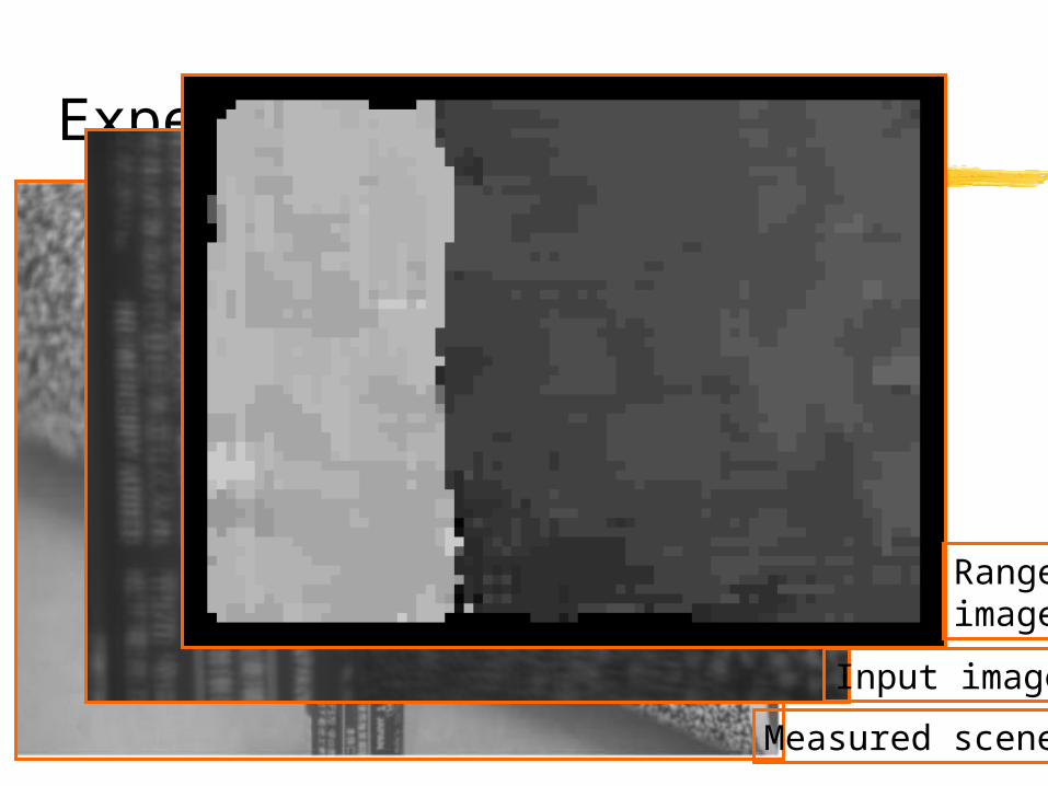
Experiment
Measured scene
Input image
Rangeimage
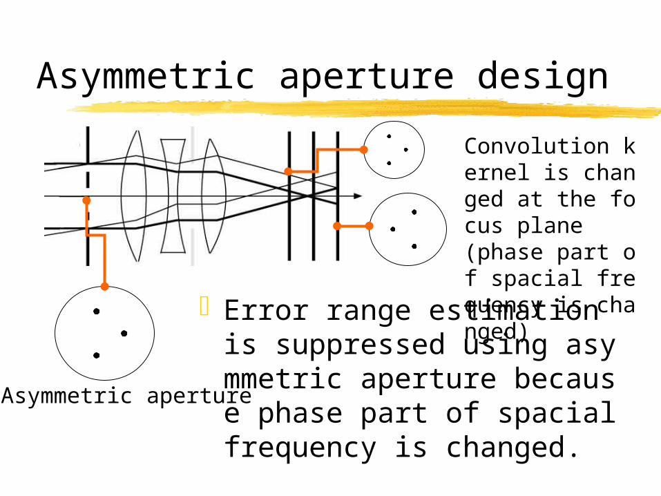
Asymmetric aperture design
Error range estimation is suppressed using asymmetric aperture because phase part of spacial frequency is changed.
Asymmetric aperture
Convolution kernel is changed at the focus plane(phase part of spacial frequency is changed)
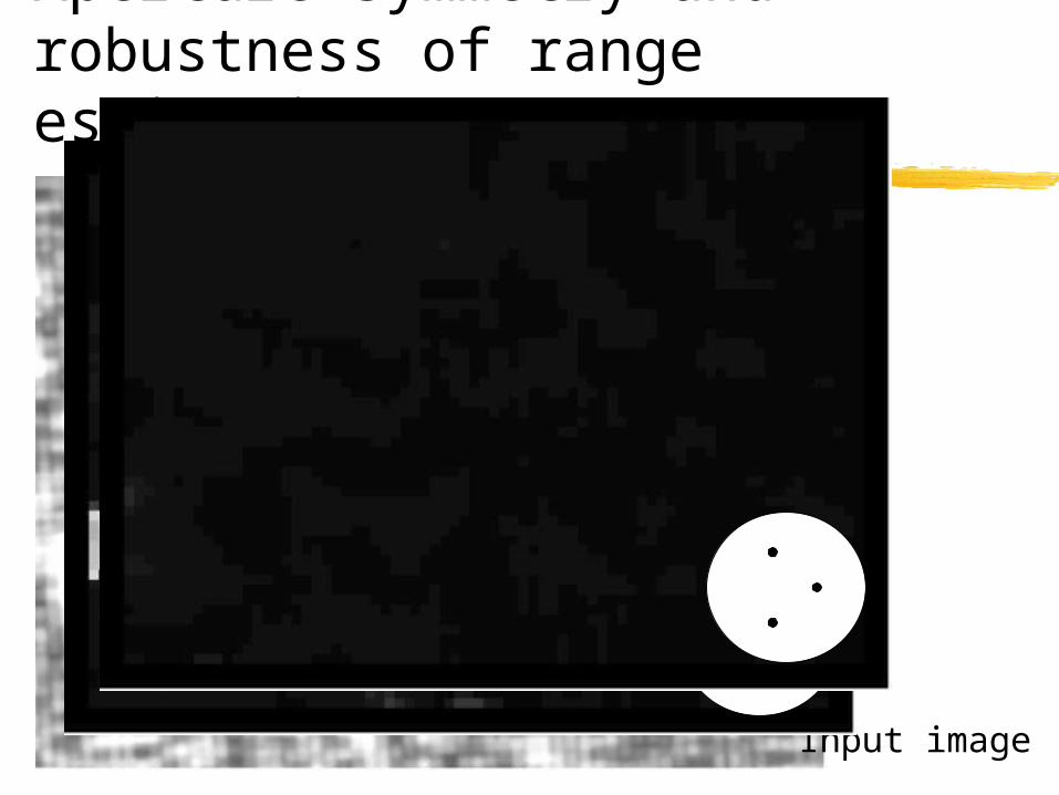
Aperture symmetry and robustness of range estimation
Input image

Motion sequence measurement using input image recording
3 images are recorded as RGB image on optical video disc recorder
Image is deteriorated by Y-C translation and cross-talk between RGB channel.
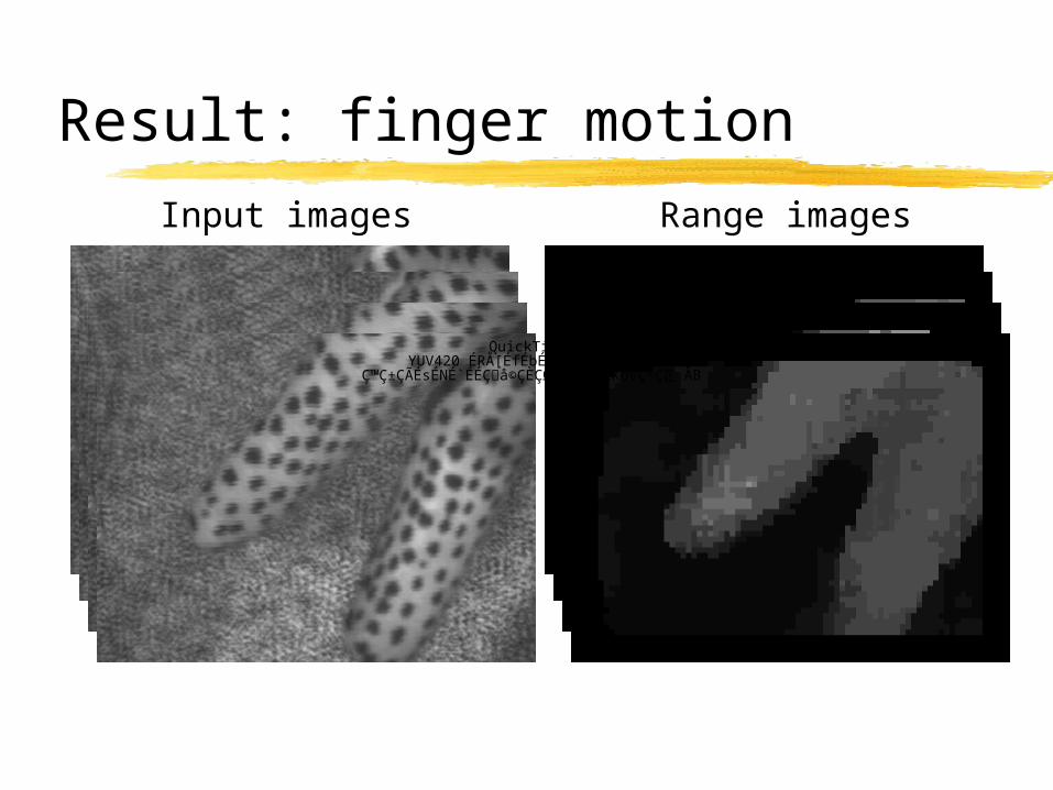
Result: finger motion
Input images Range images
QuickTime˛ Ç∆YUV420 ÉRÅ[ÉfÉbÉN êLí£ÉvÉçÉOÉâÉÄ
ǙDZÇÃÉsÉNÉ`ÉÉÇ å©ÇÈÇΩÇflÇ…ÇÕïKóvÇ≈Ç∑ÅB
conclusionsSmall/light multi-focus camera is developedCoded aperture is applied to depth from defocusStable range estimation is achieved
Range estimation/image restoration by FFT Range estimation by convolution
Recorded image can be used for motion analysis because range estimation is robust enough
Real-time range measurement is possible using image processing hardware. Simple method is easily ported to parallel hardware.
Real-time calculation usingimage processing hardware
Simple convolution method can easily be ported on image processing hardware
Massive-parallel hardware, IMAP-Vision is used for experiment
Spec: 10G instruction/sec by 256PECalculation of 25frames/sec can be
achieved. ( However, this board does not have RGB separate capture interface; experiment is calculation only)