Characteristics of the Sansui QS Vario-Matrix 1 and 2
39
PREPRINT NO. 904 (A-7) CHARACTERISTICS OF THE SANSUI QS VARIO-MATRIX BASED ON A PSYCHOAOOUSTIC STUDY OF THE LOCALIZATION OF SOUND SOURCES IN FOUR-CHANNEL STEREO Part I - CHARACTERISTICS OF THE SANSUI QS VARIO-MATRIX Ryousuke Itoh and Susumu Takahashi Sansui Electric Company Tokyo, Japan Part II - THE PSYCHOACOUSTIC LOCALIZATION OF SOUND SOURCES IN FOUR-CHANNEL STEREO Masao Nishimaki Tokyo Institute of Technology Tokyo, Japan and Kouichi Hirano Sansui Electric Company PRESENTED AT THE 43rd CONVENTION SEPTEMBER 12-15, 1972 : AN AUDIO ENGINEERING SOCIETY PREPRINT This preprint has been reproduced from the author's advance manuscript, without editing, corrections or formal review by the Editorial Board. For this reason there may be changes should this paper be published in the Journal of the Audio ConventionPrice ......... $ .35 Engineering Society. By Moil to Members ...... $ .75 Preprints may not be reprinted without prior permission from ByMail to Non-Members...$1.00 the Society's Publication Office. Permission does not constitute an endorsement by the AES of the contents of this preprint. Additional preprints may be obtained by sending request and remittance to the Audio Engineering Society Room 929, 60 East 42nd Street, New York, N. Y. 10017. Cc)Copyright 1972 by the Audio Engineering Society. All rights reserved.
-
Upload
ty-chamberlain -
Category
Documents
-
view
250 -
download
8
description
Part I - CHARACTERISTICS OF THE SANSUI QS VARIO-MATRIX Ryousuke Itoh and Susumu Takahashi Sansui Electric Company Tokyo, Japan 43rd CONVENTION CHARACTERISTICS OF THE SANSUI QS VARIO-MATRIX BASED ON A PSYCHOAOOUSTIC STUDY OF THE LOCALIZATION OF SOUND SOURCES IN FOUR-CHANNEL STEREO PREPRINT NO. 904 (A-7) Cc)Copyright 1972by the Audio Engineering Society. All rights reserved.
Transcript of Characteristics of the Sansui QS Vario-Matrix 1 and 2

PREPRINT NO. 904 (A-7)
CHARACTERISTICS OF THE SANSUI QS VARIO-MATRIX BASED ON A PSYCHOAOOUSTICSTUDY OF THE LOCALIZATION OF SOUND SOURCES IN FOUR-CHANNEL STEREO
Part I - CHARACTERISTICS OF THE SANSUI QS VARIO-MATRIX
Ryousuke Itoh and Susumu TakahashiSansui Electric CompanyTokyo, Japan
Part II - THE PSYCHOACOUSTIC LOCALIZATION OF SOUND SOURCES IN FOUR-CHANNEL STEREOMasao Nishimaki
Tokyo Institute of TechnologyTokyo, JapanandKouichi HiranoSansui Electric Company
PRESENTED AT THE
43rd CONVENTION
SEPTEMBER 12-15, 1972
: AN AUDIO ENGINEERING SOCIETY PREPRINTThis preprint has been reproduced from the author's advancemanuscript, without editing, corrections or formal review bythe Editorial Board. For this reason there may be changesshould this paper be published in the Journal of the Audio
ConventionPrice......... $ .35 Engineering Society.ByMoil to Members...... $ .75 Preprints may not be reprinted without prior permission fromByMail to Non-Members...$1.00 the Society's Publication Office. Permission does not constitute
an endorsement by the AES of the contents of this preprint.
Additional preprints may be obtained by sending requestand remittance to the Audio Engineering Society Room 929,60 East 42nd Street, New York, N. Y. 10017.
Cc)Copyright 1972 by the Audio Engineering Society. All rights reserved.

O_d_ACTERISTICSOF THE SANSUI QS VARIO-MATRIXBASEDON A PSYGqO-ACOUSTIC
STUDYOF 71m LOCALIZATIONOF SOl'ID SOURCESIN FOUR*C_L STEREO
PAR?' I: f_IARACTERISTIC_ OF THE SANSUI QS VARIO~b2TRIX
By Ryousuke Itoh and Sustmlu Takahashi, Sansui Electric Co., Ltd.
ABSTRACT
The dynamic distribution of separation by the Vario-Matrixdecoding technique is described with particular reference tothe occurrence of simultaneous and closely succeeding soundsfrom different directions. This operation is related to tileperception of directionality, including directional maskingeffects with respect to time difference, amplitude differenceand even frequency difference.
PART II: _ PSYU_OACOUSTICLOCALIZATIONOF SOUNDSOURCESIN FOUR-C_IANNEL STEREO
By Dr. Masao Nishin_ki, Professor, Tokyo Institute of Tedmology,and Kouicbi Hirano, Sansui Electric Co., Ltd.
ABSTRACT
1tm mechanism by which sound directionality is recognized by the humanear is investigated, particularly with respect to reproduction in abasic, four-channel sound field. The roles of such factors as phase,amplitude and frequency are studied, and an attempt is made toestablish a theoretical basis for the mechanism of perception.
PART I
iNTRODUCTION
Until today a number of systems have been proposed bydifferent manufacturers to effect what we now call 4-channelsound reproduction. While these systems are being appraisedtoday from various angles, the authors feel a strong need to

return once again to the very basic criteria of 4-channelperformance.
It appears that our question should not just be oneof choosing the discrete or matrix system. It should ratherbe what system, or what approach will guarantee the collec-ting, storing, transmitting and recovering of the total360-degree directionality of original sound sources. Andwhat system or approach will guarantee it with no degradationof their tone quality, and at the same time be really prac-tical at the recording and playback ends, as well as in thebroadcast station, requiring no dreadfully complicated orexpensive addition or modification of the present equipment.
Furthermore, to the operators of broadcast stations, itwill be of equal importance to be able to transmit the requiredinformation in the narrowest band possible.
The authors recall the time when RCA established firmtheories of chromatics prior to proposing the NTSC color tele-vision system, and feel that we too should benefit by an in-depthstudy of sound directionality before casting our vote on thevarious 4-channel systems thus far proposed.
For this reason, a report on a psycho-acoustic study ofthe localization of sound sources in 4-channel stereo will be
presented in the second half of this paper.
1. MASKING OF DIRECTIONAL INFORMATION
It is a well-known phenomenon that, when two sounds existconcurrently, the lower-amplitude sound is masked by the higher-amplitude sound. But to the authors' knowledge, no report wasmade until recently about the masking of one sound by another whenthey arrive simultaneously from different directions.
A recent study, however, has disclosed that the masking ofdirectionality does happen every time a high-amplitude soundand a lower-amplitude sound come in from different directions atthe same time. The weaker sound is masked by the stronger one,its directionality becoming ambiguous.
Let us introduce the results of one study. This study revealsthe process of "backward masking" that takes place when an inter-fering sound arrives later than a principal sound. It examineshow the directional sense of the preceding sound is affected bythe loudness of the succeeding sound.
The primary experiment of this study involved placing 15loudspeakers at intervals of 15 degrees each in an anechoic chamber,as shown in Fig. 1, then emitting sound from two given loudspeakersat a given time interval. Subsequently, the directions from whichthese sounds seemed to arrive were detected as closely as possible.
-2-

From this experiment, it was determined that if thesucceeding sound is louder than the preceding one by 10dB,there must be a time lag of 25 milliseconds or more in orderfor the directionalities of the two sounds to be accuratelydistinguished. If the time lag is less than 25 milliseconds,the preceding sound and the succeeding 10dB larger sound havebeen found to mutually obscure their directionalities.
It was also discovered that a succeeding sound which islarger by 20dB than the preceding sound would disguise thelatter's directionality were it not produced with a time lagof at least milliseconds.
The above pertains to the backward masking of a precedingsound, which is less susceptible to masking in the first place.Reports have been received that the directionality of a succeedingsound is much more likely to be masked in a forward masking phen-omenon. It has been found to happen even though the succeedingsound is identical to the preceding sound in loudness.
While the ordinary "loudness" masking occurs when there isa difference of 30 to 40 dB between two sounds, the masking ofdirectionality has been found to occur with no difference or adifference as small as 10 to 20dB.
This, however, stands to reason. The loudness masking meansthat a small sound is masked by a large sound to become inaudible.It could happen only if there were a considerable sound pressuredifference between them. In contrast, the masking of directionalityonly involves obscuring of the directionality of a weaker soundof a stronger sound; the weaker sound does not become inaudible.Therefore it begins to h_ppen when the difference is still small.
It should be remembered here that such are the circumstancesunder which 4-channel sound is normally heard.
In other words, at the moment when one of the four loudspeakersis producing a sound of high amplitude, our ears are sensingobscured directional]ties of the sounds from the other three speakers.
To the extent that this masking of directionality happens amongthe four loudspeakers in 4-channel stereo, the question is posed asto whether it is really necessary to transmit the masked channelsas well in discrete form. It is a question that merits serious theconsideration of us all in the industry.
After all, one always listens to four sounds s_multaneously in4-channel stereo reproduction. It is essentially different fromhaving four independent telephone circuits.
-3-

2. QS VARIO-MATRIX
One corollary is derived from the foregoing discussion:four-channel effects truly equivalent to the discrete systemwould be obtainable from a matrix system which continuallycompares the four sounds as to their loudness levels so thatit reproduces the largest sound with the clearest directionality,and the smaller sounds occuring within a certain time lag withless clear directionalities, 'rovp____v!_d_that such obscuring ofdirectionalities is within limits dictated by the psycho-acousticsof 4-channel listening, which is yet to be studied seriously.
The QS Vario-Matrix employed in Sansui's QS REGULAR MATRIXsystem has been developed on the basis of this corollary. Inther words, it continually scans the phase relationship betweenLT and RT to detect in which direction the sound is relativelydominant--and how dominant it is--both in level and timing in thesound field formed by the four loudspeakers and the phantom imagesamong them. It then utilizes the information so obtained to alterits own matrix coefficient from moment to moment (with a timeconstant of less than the 10 milliseconds necessary for the maskingof sound directionality to occur), so as to improve the inter-channelseparation without changing the output level itself.
This is comparable to regarding the level of a sound as aweight, then determining the center of gravity of the numeroussounds placed on a piece of paper, and controlling the matrixdepending on the location of this shifting center of gravity. Asthe center of gravity moves further away from the center of thepaper itself, the matrix increases the separation of the sound inthat direction. Just how this is accomplished in the Qs Varie-blatrix becomes obvious when its separation characteristic ismeasured by a set-up as illustrated in Fig. 2.
Under this set-up, a lkllz signal Js fed to the LF input ofthe QS Encoder while a 3kHz signal is fed to the X.Binput, alterna-tely varying their levels and measuring the separation of the outputsignals delivered by the QS Decoder.
Since the QS matrices in the Encoder and Decoder are botbrotationally symmetrical, only the separation of the ]kHz inputsignal in the LF channel need be measured to see what would happenin other channels; there is no need to repeat the measurementfor each channel.
Fig. 3 presents the results of this measurement. The verticalaxis of the graph indicates the signal level at the four outputterminals of the Decoder after the lkHz signal is fed to the LFinput terminal of the Encoder. The horizontal axis shows the ratiobetween the signal levels fed to the LF and LB input terminals ofthe Encoder. The right-hand region of the graph 5s where the LFsignal is larger than the LB signal, and the left-hand region is wherethe LB signal is larger than the LF signal. From the graph, it isobvious that when only the lkltz LF is fed to the Encoder, there isseparation of more than 20 dB among tbe four channels. As a signalfed to another channel (in this case, a 3kHz signal to the LB channel)increases in level and acquires greater separation, it gradually masks
-4-
the directionality of the 1 kHz LF signal. Consequently, the needfor such great separation between the LF and the three other channelsdecreases, so that the matrix actually reduces the separation ofthe LF output signal. When the LF signal finally reaches the samelevel as the LB signal, there remains separation of about 10 dB(or, theorectically, 1]..8 dB).
Then, as the 3 kHz signal grows in level, the separationof the 1 kHz LF signal becomes further unnecessary and decreases,and tile separation of the 3 kHz LB signal gradually increasesinstead.
There is one important observation to be made here, whichis that even the relatively low-level signal retains its totalenergy throughout this process in the QS Vario-Matrix, ratherthan being attenuated as in a gain-controlled matrix. In sucha matrix, the lower-level signal in the LF channel would no longerbe reproduced from that channel, only its crosstalk componentsbeing reproduced from other channels. Its total energy isdiminished.
Were such attenuation of the lower-level signal ever to bepermitted from the standpoint of psycho-acoustics, the matrixitself would have to offer the same 30 to 40 dB separation thatis required for the natural loudness masking phenomenon to takeplace. In practice, however, this is nearly impossible.
Another important criterion of the performance of a 4-channelmatrix is its separation characteristic against two simultaneousinput signals. As with the discrete system, the separation charac-teristSc of a matri× system is usually indicated for a single inputsignal. However, as soon as some artificial control is appliedto the matrix to enhance the separation, it becomes necessary toestablish its separation characteristic with respect to two simult-aneous input signals. For a matrix system could only be regardedas being able to provide the same 4-channel playback as the discretesystem if it offered such separation for two simultaneous inputsignals that the masking of directionality would occur.
The Sansui QS Vario-Matrix thoroughly takes this into consid-eration as Fig. 3 and 4 demonstrate.
It was already discussed before how the separation of an LFsignal changes as another signal enters the LB channel and graduallyrises in level. Fig. 4 shows how the QS Vario-Matrix responds tothese two different input signals under such circumstances.
Fig. 4-a. illustrates the matrix vectors of the QS Vario-Matrixwhen the LF signal is of a sufficiently higher level than the LBsignal. The matrix vectors of the RF, LB and RB output signals areentirely opposite to that of the LF signal. It follows that, theo-retically, no crosstalk appears in the three channels and theseparation between tile I,F and the other three channels is infinite.
Then, once concurrent signals of identical levels enter theLF and LB inputs of the encoder, the same matrix responds as shownin Fig. 4-b., where the theoretical separation between the LF and LBchannels is ]1.8 dB.
-5-

Furthermore, when the LB signal is sufficiently higher thanthe LF signal, the matrix changes as shown in Fig. 4-c., so thatthe separation of the LB channel from the other three channelsis infinitely large but that of the lower-level signal in the LFchannel becomes monophonic. These variations of the QS Vario-Matrixare easier to understand if one considers the output characteristicof the QS REGULAR MATRIX itself as illustrated in Fig. 4-d. Thesolid-line curve in the graph represents its output characteristicwith respect to an LF input signal. By automatically altering thematrix coefficient, as in the QS Vario-Matrix, the separation of agiven point from the LF signal undergoes a change as indicated onthe graph. The dotted-line curve represents the same characteristicregarding a signal in the LB channel.
The QS Vario-Matrix thus exploits the peculiar properties ofthe human auditory sense reviewed earlier in this paper. In short,it takes advantage of the masking of directionality and, whilepreserving the total energy of each input signal, provides a 4-channelsound field which embodies the most important virtues of thediscrete system.
3. TltE SPLIT~BAND _S VARIO-blATRIX
From the foregoing discussion of the masking of sound directional-ity and the characteristic of the QS Vario-Matrix, it should beunderstandable why this matrix provides aurally sufficient separationamong the reproduccd four channels. And in actual listening tests,it has startled many a doubting engineer.
But hopeful of still more improvement, we set out to see if wecould not better profit from the directionality masking phenomenon.What we eventually did was to screen the decoder input signals intolow and high frequency bands, utilizing a filter. These signalswere then processed through separate QS Vario-Matrices for separatecontrol of the matrix coefficient in each hand. This additional
technique, which we call band splitting, improves tile separationagainst two simultaneous input signals to such an extent that it ispractically the same as when only a signal enters the encod2ng matrix.
4. THE FUTURE OF 4-CIIANNEL STEREO
The Sansui QS vario-Matrix technique we have reviewed in thepreceding paragraphs, while it is a matrix system, has given us adegree of inter-channel separation that is aurally indistinguishablefrom that of the discrete system.
Let us now turn to a very fundamental question having a signif-icant bearing upon the future o£ 4-channel stereo. It concerns theutilization of information-storing and transmitting space, and hasa very interesting analogy to the process leading to the standardiza-tion of the color television system.
In the earlier days of color television, it was generallybelieved that color television _ould require a frequency hand threetSmes as wide as monochrome television. Since the latter utilizes6 mhz, this meant a frequency band of 18 mhz was necessary.
-6-

However, RCA then came up with authentic theories of chromatics,demonstrating that no harm would be done by broadcasting onlythe principal area of the picture screen in color while trans-mitting the small, unessential areas in black-and-white. Thiswas a major discovery that eventually led to the use of 6 mhzfor color television as stipulated by the NTSC or PAL systemtoday. No viewer has yet been heard to complain that small areason his color television screen were without colors.
The authors wonder whether the same logic would not apply to4-channel sound reproduction. And it is this line of thought thatis behind our proposal that a relatively strong sound be reproducedwith distinct directionality, while simultaneous weaker soundsare reproduced more or less monophonically. We on our part areaware that more advanced theories need be established before we arethoroughly able to substantiate such a proposal.
When the broadcast industry started to contemplate color tele-vision, it had already been known that all colors were separableinto three primary colors, and that any color could therefore bereproduced on the screen through the use of three transmitting spaces.To our regret, however, today's psycho-acoustics has not even givenus the answer to the msot basic question of how many channels arereally needed to transmit the complete 360-degree directionality ofa live sound field.
Had the same kind of ignorance been prevalent in the initialstage of color television, it would have been asserted that, to showa rainbow on color television, called for 42 mhz (6 mhz times 7)since it consists of 7 colors.
Hence it is our contention that the question should be studied,with extreme care at the present stage of 4-channel stereo technology,whether four separate spaces are really necessary to store andtransmit the information required for 4-channel sound reproduction.Otherwise, a great deal of research funding could go down the drain,and in broadcast, bandwidth could be wasted that might be put toother important uses.
5. CONCLUSION
It is not precisely known at the present time how many channelsare really required to transmit the total audio information generatedin a live sound field.
Should all the required channels to made available, it isstill not necessarily guaranteed that sound reproduction of a phen-omenally better quality than the present systems utilizing two orfour channels will be obtained, especially in view of the peculiarcharacteristics of the human auditory sense, such as the masking ofdirectionality.
Se attentpts were made, successfully, to take advantage of suchpsycho-acoustic phenomena in the design of a practically possible4-channel matrix system employing two channels. The resultant matrix,
-7-

called the QS Vario-Matrix, provides separation of more than20 dB between any pair of channels against two or more simult-aneous input signals, producing aurally sufficient sound-fieldeffects.
It is nevertheless undeniable that psycho-acoustic studiesof the sound field information are gravely underdeveloped andneed closer investigation in the future, if we are to furtherenhance the quality of 4-channel sound reproduction.
i__l 2 meters
Fig. l

? v0 3 kHz
'_._o".I_ %0t,._p_,_d_osc I
Fi9 2
LF input =1kHz ( Measuredat I kHz)L F
0 - LB input=3kHz .-_""'_ ................._;_,..-0
_,.,,,_._........................ . ,-_ -lo
dB _?,:'_. dB
_.,_,., L B
_ RB '_'_t,_,
-30 _ I I I f _ I -_ I--_-30-30 -20 -10 0 *10 +20 oo
dB LF/B dB
Fig. 3

LFILF
/j/l/
(a) _LB CF
LF /
_'" _,,i__ RFLee <Z\,_--_ RB CL CR
////
RB (d)
· LB (c) Fig,4
LB

PART I I
1. INTRODUCTION
It was pointed out in Part I of this paper that there existsa definite need for studying the psycho-acoustics of sound repro-duction. This Part II is an endeavor in that direction, Jn thatit has as its purpose the investigation of the mechanism by whichsound directionalities are determined in a basic four-channelsound field.
First of ail, it is clear from the structure of the humanhead that, when a sound source is located directly in front ofthe face, the ears naturally sense identical sound pressures withidentical phases (or arrival times).
By the same token, if a sound source is located in a direc-tion other than straight ahead, the sound pressures and phasesexperienced by the ears are naturally diffe.rent.
It is thus generally known that the human ears sense thedirectionality of a sound source as differences in sound pressureand phase of the sound waves converging upon them.
It has not been ascertained yet, however, whether the soundpressure or phase difference is the decisive factor, or how thetwo interact in deciding the directionality.
A simple experiment gives us some insight into this matter.Suppose a pair of speakers are placed to the left and right infront of a listener. Then, sound is reproduced under two condi-tions:
Condition a: Feed signals of identical frequencies to thetwo speakers, keeping them in phase but changing their levels.
Condition b: Feed signals of identical frequencies to the twospeakers, keeping their levels identical but changing their phases.
As Fig. I shows, under condition a, the velocity potentials( La, ¢Rb) produced at the left and right ears possess differentphases, so that the directionality of the reproduced sound imageshifts toward the louder speaker.
Under condition b, however, the velocity potentials (¢Lb, ¢Rh)produced at the left and right ears have identical phases and onlytheir magnitudes differ, so that the directionality hardly movesoff the center.
What this means is that a difference in the intensities of
the sounds from speakers is sensed by the ears as a phase differ-ence, whereas a difference in the phases of the sounds from speakersis detected by the ears as a difference in sound intensi'ty.
9 -
It may therefore be said that a phase difference at the earsis the primary factor in determining the directionality of a low-frequency sound source (approx. below lkHz), as the ears are netsharply directional for low-frequency sounds.
However, for a higher-frequency sound source whose wavelengthJ s the same as or shorter than the distance between the two ears,a sound pressure difference seems to he a more Lmportant element.This is because any phase difference at the ears will then begreater than 180 degrees and no longer sensed by them; the direc-tionality of such a sound source is merely felt as a result of thedirectional sensitivity of the ears.
Of course, the directionality of a middle-frequency soundsource is likely to be decided by an interaction of both the phaseand sound pressure differences perceived by the ears.
Hence, it is the underlying proposition of this paper that aphase difference at the ears is what determined the directionalityof a sound source whose wavelength is longer than the distancebetween the ears (which, in frequency, roughly means lk}Iz or lower).
In the following paragraphs, the phases of a sound sourcesensed by the left and right ears are first computed in terms ofvelocity potentials, whereby the directional angle of the soundsource is determined as the angle at which the difference bet_eenthose phases disappears.
To put this more simply, assume a man facing front is listen-ing to the sound from a speaker located to his front and left.The phases felt by the left and right ears are naturally differ-ent (see Fig. II). Then, as he turns his head to the left, thephases become identical at a certain angle. This counter-clockwiseangle, 0, is obtained when he squarely faces the speaker, and isdefined as the directionality or directional angle of that soundsource (in this case, the speaker).
The same logic is then applied to four-channel sound repro-.duction to see how the directional angle of a sound source isaffected as the phase and sound pressure in each of lhe fourspeakers vary.
2. THEOI_tiT[CAL BASIS FOR SOUND DIRi!CTIONALITY
We seek to learn theoretically the mechanism by which thesounds from multiple speakers come to give a sense of directionalityto a listener seated at a given position. For this purpose, how-ever, it should be first studied experimentally how the phase andsound pressure differences at the ears, and an interaction of them,influence man's directional sense.

Only then can we compute the magnitudes and phases of the
sound pressures generated at the ears when sound of specified soundpressure and phase is radiated by multiple speakers. Those valuesthen will be substituted in the formulas derived from the experiments,to ascertain the directionality of the original sound source. Ofcourse, in so doing, the directional sensitivity of the ears, as deter-mined by the head and conchae, should also be taken into consideration.
Now, suppose n_ speakers located arbitrarily are emanating soundsof identical frequencies but of varying levels and phases, with aman seated in the middle facing a given direction. Then the totalvelocity potentials at the left and right ears are given by
_,h,:/, - -iT il,:-Jr-- 2 _.,_ok. i n 2sm i
_^,a(,o , [ i ],=1
_L,MI<.2= -tl ) _,, +J) ,,u;,_k_51:/-a D . s _': 2 ' '
i=] ri [. 2- slnJ_[
_ ._iI((2:- #,! .-j(rJ, 'fi..,i,:)k [ 2 ]
i=l
where 4_]ki = the complex volume velocity of the i-th speaker,
ri = the distance from the i-th speaker to the middlepoint between the ears,
K(Oi) = the directionality coefficient of the left ear, inwhich case it is K(2_-ei) for the right ear, as theears are located symmetrically,
D _ the distance between the ears (D<< ri),
_L = the complex velocity potential at the left eardrum,
_R = the complex velocity potential at the right eardrum,
(_i = the counter-c]ockwise angle of the J-th speaker fromthe center-front direction, and
k = the phase constant, 2_/X.
Then the sound pressures at the left and right ear's are ex-pressed as
i_, ,,,oa J"'.""_" _"' '''° ,_ J'""'_(" [ 3 ]
where Po = the atmospheric density, and
= the angular frequency.
]1 -

These sound pressures can be thus computed once the velocitypotentials are determined.
There are two difficulties, however. First, the relationshipbetween the sound pressure difference and the phase difference atthe ears and the directional sense they perceive has not been experi-mentally elucidated as yet. Second, sufficient data are not availableon the directional sensitivity of the ears.
In each case, the difficulty of measuring those intangiblequalities is the reason.
Admittedly, once these difficulties are resolved, precisefigures could be obtained by applying formulas [ I ], [ 2 ] and[ 3 ]. For our purposes, however, we propose to approximate theresults by making two assumptions:
(1) That the directionality of a sound source is determinedfor the most part by its middle or lower frequencies (approximate]ybelow lkHz). That is to say that it is determined by the phasedifference at the ears.
(2) That the directionality of a sound source is the angleat which the phases at the left and right ears become identicalas the listener turns his head. This is in spite of the fact thatit should ideally be defined as the directional angle of a singlesound source at which, when that single sound source is located ina given direction, the same phase difference is perceived at theears as was perceived of the sound source whose directionality isbeing sought.
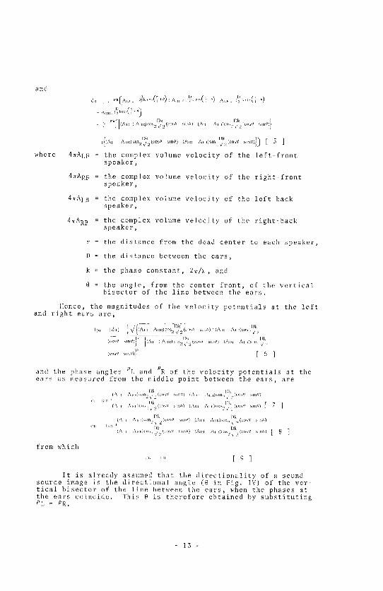
3. APPROXIMATION TtlEORY ON THE LOCALIZATION OF A SOUND SOURCEIMAGE IN A FOUR-CHANNEL '2-2' POSITION
The following analysis is based on the assumption that fourspeakers are placed in tile four corners of a square, as in Fig. IV,with the listener positioned at the dead center. It is also assumedthat the center-front direction in the figure is where 9 = 0, andthat sounds reproduced by the speakers are identical in phase butdifferent in level.
Then, substituting the assumed values in formulas [ 1 ] and[ 2 ], the velocity potentials at the ears are given by
I _id,[AL I il)k ' _ jD -O, "_''_(,_'') AE
_Jrl,[AI I :J 2 ? _(c,.,tl ,.dl) , ] _ 4r
s-i,k_{[Aml. A,. cos.__2Dkz. ({ost M Il/ (A,m Al _0co_2)kg(cosJ ........ }
[
12 -
and
r _,,,,,(',,"):A,,, '?_',,-(,,,) ^..... ,,,,,(; )_,ilt 1 c_jrk(Ai,E _ )1) I - _ j D/ - j ) I
I) :, A...... :?,_O'(T_']A,ii)cos2,/2(cos/ sm/t) (Anl .'\tl.)CO_,,_,2/.(tr>sOk( J
,{:^,, ?k , .......ql[ ]Aim)sln,),?2(cos/ s,n#) (Am AllO,sln2x/2(cosI
where 4_ALF = the complex volume velocity of tile left-frontspeaker,
4_ARF = the complex volume velocity of the right-frontspeaker,
4_ALB = the complex volume velocJty of the left-backspeaker,
4=ARB = the complex volume velocity of the right-backspeaker,
r = the distance from the dead center to each speaker,
D = the distance between the ears,
k = the phase constant, 2_/X, and
0 = the angle, from the center front, of the verticalbisector of the line between the ears.
Hence, the m.agnitudes of the velocity potentials at the leftand right ears are,
,¢, hi,d _._/{(^,, ,)k fJDk
i Aim)<os 2 y/2 (cob MI1/I) ' f/\Jll ^1 I:)Clm2 _/ '2
(_o_// sm /) (,M, : A,,)sm 2 ¢.?to,t/ sm/O (A., Al .)s,n,,D, k
.........'T [61m
and the phase angles 9L and PR of the velocity potentials at theears as measured from the middle point between the ears, are
l)k )k(All AtiH)_]n2_i2(cost _m/I) (,\1<_ ,\l,ll)hln2,,2(t¢3_] sm/Il
51 tan L l)k / I)k(All Al.)Ct>S,2<2(cc_s smtJ) t,\l. Aiid{a_.2 /2(tos _mo) [ 7 ]
I)k l)k(.Stl AIIIQSlIL!_ 2(CoSI] Mil/I) (:\ltl ^Ill)SIll,2 _ [!(tos! SIll//)
c. tan ' Dk I)k(All .'\l{.)cos2V, 2i_l.s] [aH/l) (ALII Al i,)¢os:! x :) (CON MII//) [ 8 ]
from which
s',. _" [9]
It is already assumed that the directionality of a soundsource image is the directional angle (O in Fig. IV) of the ver-tical bisector of the line between the ears, when the phases atthe ears coincide. This O is therefore obtained by substitutingOL = PR.
- 13-

So, substituting PL TM PR in formulas [ 7 ] and [ 8 ], we have
) Dk f l0 1
from whichDk
sm .... (c_s/ sm/OAm_ - Ai,m_ _
l\.m /M 4_ l)k...... _. (__,J ....,) [ ll ]
When Dk____ _ , namely D (( × (which means, if D = 15 cra,2v-z<< 2 V-z
substituting it in X , f(( 1.6 kHz),
Al I l\1_1_ coM! SlnlJ I rani/ r
12 1
Let us now derive the directional angles of the following eightcritical points from equation [ 12 ], as an example.
Table 1
Sound Pressure Sound Image Sound SourceInput into front Each Speaker DirectionalityO Directionality'
__E=45o 45eLF only ALFa0' ARF=ALB=ARB=O ' 4
RF only ARF_0, ALF=ALB=ARB=0. _ _r=_45 o .45 o4
LF=RF only ALF=ARF_0, ALB=ARB=0, 0=0o 0°
ZS__=90 ° 90 °LF=LB only ALF=ALB/0 ' AEF=ARB=0 ' 2
Table 2
Sound Pressure Sound hnage Sound SourceInput into from Each Speaker Directionalit T a Directionalit}_
LB only ALB/0 , ALF=ARF=ARB=0. h=-4S ° 135 °
RB only ARB_0, ALF=ARF=ALB=0. -_=45 ° -135 °
LB=RB only ALB=ARB_O AiA:=ARF= 0. 0=0 ° +_180 °
RF=RB only ARF=ARB_0, ALF=ALB=0. --_=90 ° -90 °
Tables 1 and 2 show the computed results, Table 1 demonstratesthat the directional angle of the reproduced sound image does indeedcoincide with the directional angle of the originat source in the livesound field.
14 -

Itowever, Table 2 shows that the reproduced sound image d_rec-tionality deviates front the real directionality by exactly 180 degrees.This is because, if the listener squarely faces the sound source, andif another sound source is located directly behind him, there is nodifference between the phases felt at the left and right ears. So theears cannot distinguish between the front and back directionalities.
Thus, when a sound source is located in one o[ the four direc_tions listed in Table 2, the theoretical directionality of its repro-duced image shifts 180 degrees.
In actual listening, however, a listener facing front isnaturally able to sense the left and right directions, or the plusand minus of the reproduced directionality 0. Then when the soundsource is located at the center back, he normally differentiatesbetween the front and back from experience. If the frequency of thesound source is high, the directional sensitivity of his ears facili-tates detecting the dif£erenee.
Next, let us actually apply this theory.
Suppose microphones l, 2, 3 and 4 are p]aced in almost identicallocations in relation to a relatively distant sound source, as illus-trated in Fig. V. Further assume that each microphone possessescosine directional sensitivity, and that their outputs are to beseparately amplified and transmitted and then fed to the LF, RI;, LBand RI3 speakers.
Under this assumption, if the distant sound source (which, forour purpose, provides a 'Front input signal') is located in thedirectional angle 8' from the center front direction, and if it iswithin the front quadrant defined by the maximally sensitive direc-tions of microphones 1. and 2, then the inputs into the hF and RF
speakers are proportionate to cos (--_-g') and cos (__+0'), respec-tively. No input signal enters the two back speakers.
Therefore, substituting these values in the left member ofequation [ 12 ], we have
t n') O I i · t,
Anl ,\l n co_,( { ti') O [ _/f s ti' I UHle] '
Consequently,/ tan_/' ] tan//
wMcb means g = 0'.
It follm_s that the directZonal angle of the sound source, asviewed from the microphones, matches that of the reproduced soundimage heard at the center of the four speakers. And the same holdstrue for a sound source orkgi, nating in any other quadrant.
15 -

Conversely, a sound image call be produced from a signal ill anygiven direction, say e. For instance, if the 0 is inside tile frontquadrant of Fig. V discussed above, it is only necessary to distribute
the signal to the LF and RI: speakers at the ratio of cos (_E_ 0) and
cos (-_+e), feeding no signal into the back speakers.
4. WHEN TIIERE IS CROSSTALK TO AI)JACI!NT CtIANNELS IN A FOUR-CIIANNEI,_PEAKER POSITION
Let us now exami,ne how the Foregoing analysis applies to afour-channel system having two information-transmitting channelsand where crosstalk to adjacent channels is unavoidable.
Assume a case where crosstalk, as determined by crosstalkcoefficient c, exists between each channel and its adjacent channels,and where the Four speakers are operating in phase with one another.
From formulas [ 4 ] and [ 5 ], the complex volume velocitiesof the Left Front, Right Front, i,eft Back and Righl. Back speakersare 4_Ai.,F, 4_ARF, 4=ALB and 4_ARB, respectively, if there is no
crosstalk among the channels. To simplify the process of computa-tion, however, we'll divide them by 4_ and obtain Al,i: , ARF , ALB andARB as the complex volume velocities.
Then, if there is crosatalk as assumed above, the four speakerscome to have complex volullle velocities of
Left Front speaker ALF+CARF+CAIB,
Right I:ront speaker = Ai_F+CAi_F+CARB,
Left Back speaker ALE+CALF+CARE, and
Right Back speaker ARE+CARF+CALB.
tlere, we again define the directionality of a reproduced sound-source image as the directional angle at which the phases at the earsbecome identical, as measured from the center front. Then the relatio:ship between this angle 0, and those complex voJume velocities can bederived by substituting those values in equation [ 12 ]:
(l\l i ( .'\,t {/\1,,) (Al/ti I Alii cAI u) Al F .\lul I rani]
]'he end result is thus identical to equation [ 12 ]. Which means, ifa listener is positioned at the dead center of the square formed bythe four speakers, the directionality of the reproduced sound imageremains the sallie as when no crossta]k existed, so long as the crosstalk from each channel leaks to its adjacent channels in identicalproportion_ and in phase.

Now that tile directionality o{ the reproduced sound image
has been confirmed to remain unchanged, let us examine how the
sound pressures at the ears vary.
To determine the ve]ocity potentia]s at the ears, we sub _
stitute equation [ 10 ] in equation [ 6 ]:
I_,l,] I!ml 1 I(AT_
I)k
r Alu_)_os2_/2(cos sin/l) (A,i At.)
I_k. _,,,)} [ ] S ]cos V 2 (c_ 7
Then, if the magnitude of the velocity potentials is I¢[.
when there is cros_talk,_ i. ts ratio to its counterpart withoutY
crosstalk, I&L]= ICRI_ I¢10, is)k
ifil _ (Al i /\u* 2_,Xm '2<Al n)c_)s,_2, (_o_, sm/;)
)") '_' (At i Alu_)to%2 ¥ '! (cns Jsmn)
I)k
(knl ,,\ri, 2, A[i _,'Ai_i*)cosL ,! (co_// _l.//)I)k
(,Mn Ar.)c_s, . _(<osf/ sm.)- 2
IJk . MIl{J) (Al I 3k _111/1)(Aln ,'\p ii)c,Js,! . 2 ( ,s .\llll)COS212(coMI
I 2t )k I)k(A,, \,.)_,., , (.,.. _,..> (A., .,\,,,)_._,.... _o_ ,,w,) [ 16 ]
The sound pressure at each ear therefore increases by the amount
represented by the second term of the right member of the above
equation.
If the micro'phones with cosine directional sensit4vJty are
again used to pick up a 'front input signal', the ALF , ARF, ALB and
ARB assume these values:
JAt Il: Al/. 0
Substituting these values in equatJon [ 16 ],)k /
1' ;! ((.os/] Sill// cob2 · '2(Cos _nnf})10bI '!< )k
!0h) _'2(' si/ _mu c,,s2 (2(co_n stnn))k
¥ 2(('oq{J _bll/J{oh, /2 (cos/] Mn/l))k
_/2(c,,_/I sm0)c,>.,, 2(t'_'_ sm/;)
Then tile sound pressure increases at_ for instance, the Center
Front location and in tho Left Front speaker can he computed.
In other words, ,,hen 0=0, :ii', ....
If c = i or -3 dB, then ';' ._lLt,'l_,d}_)
When 0 = ___ , I0, _ 2_,,,,l>k4 ,?h, 2
- 17-

For a sound source whose frequency is I__ << __. , -i._ 1 ,
If c _21 or ( klB)_ j6jj_ic, 2 Il (7 t6dlI)
Fig. VII shows how tile sound pressure in each channel increasesas the crosstalk changes.
5. 4-2-4 MATRIX SYSTEMS
Any two-ctlannel matrix system produces a please difference of180 degrees as it tries to matrix a complete 350 degrees of sound.Diffcrent systems havc been proposed to date which differently dis-tribute this phase difference and the inevitable crosstalk. Ferour purpose, it will suffice to study the localization of a seundimage in two representative systems which are already in practicaluse .
(1) A Matrix System Which Phase-Shifts the Rear Channel Signalsby +90 © and Which Distributes the Crosstalk in a RotatJonallySymmetrica] Fasi_ion.
Such a matrix system dc]ivers the output vectors as shown byFig. VIII, with each speaker generating a complex volumc velocity ei'
I.l: b- uXJ m _ \m ;_ \1 n}
RF I;- (,\m _ALi j_ .\m_)I,B Ix (,\] , c'/lm_ l, ,\L I_)
RB l-(,\1¢: _ \EI_ ), knJ_
Substituting thesc values in the place of Al.F, ARF , Ai, B and ARB in
Formulas [ 4 ] and [ 5 ], the velocity potentials perceivcd at theleft and right ears, _L and _R, are
-.k( )!51 _r (Att tAM jc.\llOCO_ 2_ 2 c_l_ll .lll//i jl \11 i \1_1 jr,\illkI)
I)k _*_// %till/) (\ill \ti J, \1 _U_S,> 2'to_/ stCld /_Lll 2 _ '2 ( C - %
kD
l_Am , \kl J_AlUOStn2_ 12t_c_/I _tl/lll t ,\II' ,AHI: Jc-xlJ:_
kl) kI)
tc_S¢ _ _9[(°s// ,in?i) jl \11_ , \Ifil J, \ti J_Ln _ _ 2(t_*_d blt_//}
, J) _[ll//) j( 5[_h _[ _ Jt B[i )
kD
kDs )[i. (._1 [ (,XH[ .XHH i Xl [*_l'_)_> Hob / .ill/I}
-'2
k)
( \l{t i At i \1 i_ t .\l:l*/Co_ ! ,) (t<)h/I _lll//) tL \t*l \1 i
I)[) L _ // _11112) ([ \Il 5 b I > ( (t)st/ _lll/l_
kl) kDj lC,\tH \II/CO_> ((c)h) _tn/) _l,\ll .\l;h to-,, )(tO_ stn//)
)
t:\l i I .\t_t .\lin i ._l )_lll,i ) cost/ Sill/J)
_" }1_,\ .... \,, :\ .... x,,:)..... )_o_,, .... ,_ [ 18 ]
18 -
and
i k kD
_,_t_ _ _ All - _,Al_l r A.. , cAN0cos; 2 '/2 (cos// sm0)k)
, (Am' cAH Al,. ! cAm0cos2_ / _ cos// [ sm//) _,(Am / "\u.) .
k) kD /i<sln,jl/_(Cosl/ sin/} ) i,(/\l i AliB) Slll2x/2(cosY;sln/l)
/{c(Alu kD , sine) c(Aii kI) sm/t), A_ .)cos 2 d 2 (cos Alu0 cos 2 d 2 (cos[/,kl)
(Al I /'/\Iii Ali. iAI,I)snl.).7__,, (cos// s It/
kl) }_,(A., _A,,. A,.,, ,A,_,0_,%.,2(cos. _._//) [ 19 ]
Let us now see how these formulas apply to an actual record_lng situation involving a 'front input signal.' where a signalenters only the Left Front and Right Front microphones.
Since ALB=ARB, substituting them in the above two formulas yields
s I) k )
I_ ( A,a. _ A,, )c.s 2 _t 2 cos sm0) (Alii' i cAi.t')cos2_ / _(cos// ' sm//)
kl) kD
L cAl,i, bill 9..x) 2 (c°s(t , sill/J) C/\ltl s _x,6'2 (cos_J Sill//)
jQAIm'' kD k )[ cAlu ) mn 2 _/2 (cos# sin/t) (Alii' r tala') sln2 _v2 (cost/ Mn/J)
kI) kD }1"At"'"ts2,,/2 _:°_'/' .... /ii ,,'a_,t ..... ,, 2(co_,/_, .... ,) [ 20 ]
id,
0m_ ? r _(l\m k]) # kl), cA"')c°s2 _/2 (cos sm_/) (Am': cA,_)cos_,/2(cos# , sm/l)
....../D(........,)., .......?]:,(.........)/{(Ali kl) kI)cAlll')slll2 '/'2 (COSt/ sill//) (/\Ill' cAl,I )sin 2 v/2 lc{m// Sill//)
kl) kD ......)}) [ 21 ]CALl (oh [ 2 [ SI/ sill//) c.X}{} CO_[_ 5/ 2 (_OSl/
To simplify the computing process,
kD Ii kD(All c,'\ld)cos,>~_/2cos sm/0 (/\m cA_j)cos)2_2/ (cos/t sln//)_a
m kD kI)c/\Il s_12,2(cosO sm[/) c:\m sm2c2(cos// sm/I)' h
kD , kD
(,'\l_ cam )sm L /2 (cost/ sm//) (Am c"\ml)sm2 _/2 (cos// sm/t) .ckD
(All cos _ '2 (co_ll slnr/) tam cos kD 2 (' sit smt/)r=d
Formulas [ 20 ] and [ 21 ] can then be rewritten as
0, :/_"((_, ,,),¢. d)_ [ 22 ]
_,_,:/'_((,,,,),(_,_)) [ 23 ]
19 -

Accordingly, the phase angles oL and PR of those velocity poten-
tials, as measured front the midd]e point between the ears, are
c d I_-_ t,._-_ [ 24 ]a {
and
{_,,_:' [ ZS ]!'1_ tan- I [_ b
Recalling that the directional angle 9 of the reproduced soundimage is obtained when PL=PR,
c d ¢ I d
_.l; _, b [ 26 ]
which can be rewritten as
,,_ua [ 27]
Substituting the original values of a, b, c and d in equation[ 27 ] and rewriting it, we have
icl) ] / '_(/_ll!:2C\ll _l:l)Mrl z2(co_f/ sin/J) ,_ AiH- :_cAiiAiii)
, , k ) _t,..,,..........) A,,,,)<, )[ ]x sill _/?
Then the magnitudes of tho velocity potentials at the leftand right ears are
!,_I ].:(.[b)_ (,, a)_ [ 29 ]r
and16.1 ] FCab)__]_,,0' [ 30 ]r
As the LB is phase-shifted by +90 degrees from the LF, andthe RB by -90 degrees from the RF, it is expected that the ve]ocJtypotentials at the left and right ears are different in magnitude.To compute the ratio between the magnitudes,
/
- 20 -
Of course, if c=0 (i.e., no crosstalk) as in the discrete system,then b=d=0, whereby
2;',, I =lI_hd
Next, for a sound source whose frequency is kD24-Z<<-z' sin _.×.
Therefore, equation [ 28 ] becomes
_(A, k3 o o 1 2 kD (cos0 F sin, )124 2cA,.iAm.) /_(cos sm ) - 2(Am. 2cAi,iA,r)
={c(A,r21A,,,,'2) I(1 2c'")A ,'A ,' kpsh,, [ 32 ]
which is further rewritten as
Au, z A,i.. _
(I , 2c)(A[jp _ , Au,.'9: 2(1 2c i 2c:)A,_A,, lan, [ 33 ]
EXAMPLES OF COMPUTATIONS FOR TIIE DIRECTIONAL ANGLE 0 AND VELOCITYPOTENTIAL RATIO
(a) When ALF=ARF , and c_ er -3dB;
Since ALF2-ARF2=0, we substitute it in equation [ 33 ] to
obtain 0=tanO, from which 0=0.
Hence, although crosstalk does exist, the phases at the left and rightears become identical when 0=0, namely in the (:enter Front direction.
Meanwhile
kD
.'(.\ .... ',,) sm2_[;I!l,l a b ('\il iam)(] !c)cos2_/2
kD
c c tall 2 _/2kD >1
c tan 21' 2
Therefore, ._L).iR . If kD _ 0.3 (which is to say f # 300 Hz, assuming
D=i Scm) , x/ 2
i,h 1 ! (1 707 _ 0 707 tan 0 3 =i,,htI 1 . (} 7O7 il 707 tan {),3 30
(b) When ALFe0, ARF=O and c=_or -3dB:
,\1 p2
From equation [ 33 ], we have (l yeA,,7 '"'%
from which I 1 I_,n,2c
Substituting c, we obtain _ ,, 0u_ t_,_, or , :_2_I , _2=
21 -

To find out the velocity potential ratio between the ears,we again put kD = 0.3, in which case2v-_
. kD , . k)a -Al i.,cos 2 _/_ (cob stn/t) , cAl,i cos]] _/2(cos / I sirv/)_l 64l\1t
k) ob =cAivsm2_/2(cos ' _ln//): 027,Mi
Therefore
I_h.I d b I 91
1',5.[ ' a--); -- ] 37 [ 39
(c) When four microphones having cosine directional sensitivityare placed as shown in Fig. V to pick up a 'front input signal':
^,, Aco_(_ .') [Under that condition, ^., ^.o_(_ .'_ ;
c _J2 ( :id[I) /
It is also assumed that c= il_ (or -3 dB). Then, substituting thesev-f
values in equation [ 33 ], we first obtain
': /'0%1]' S I11It ' [ 34 ]
(1 ' 2c) (I ! 2c 2c:)co'¢1/'
into which we now substitute c=0.717 to get
C{3SII'siiiII'
J.:;o7_7o'_¢,,_,.,,,,_...... [ 35 ]
Again, based on the assumption that Dk = 0.3, the directional2v--_
angle of the reproduced sound image can be computed from equation[ 35 ]. Fig. IX graphically shows the computed results, and alsodemonstrates how the directional angle of such a sound image shiftsas the amount of crosstalk is controlled.
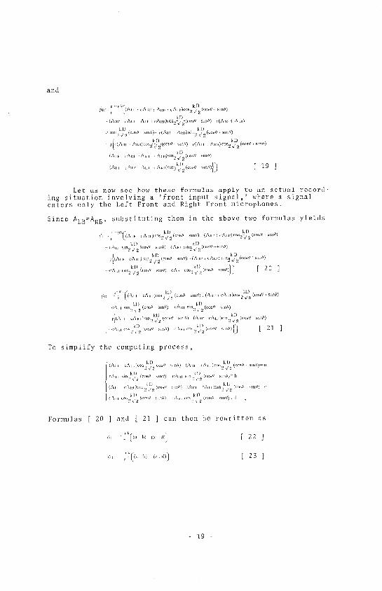
Fig. X extends the foregoing analysis to a complete 360 de-grees of directionality, it demonstrates that the matrix systemunder review locates sound images with complete left-right, front-back symmetry, and also that Jt does not dislocate the Center Frontposition. It reveals, however that such a matrix tends to shrinkthe psycho-acoustic distance between the front two speakers andbetween the rear two.
- 22-

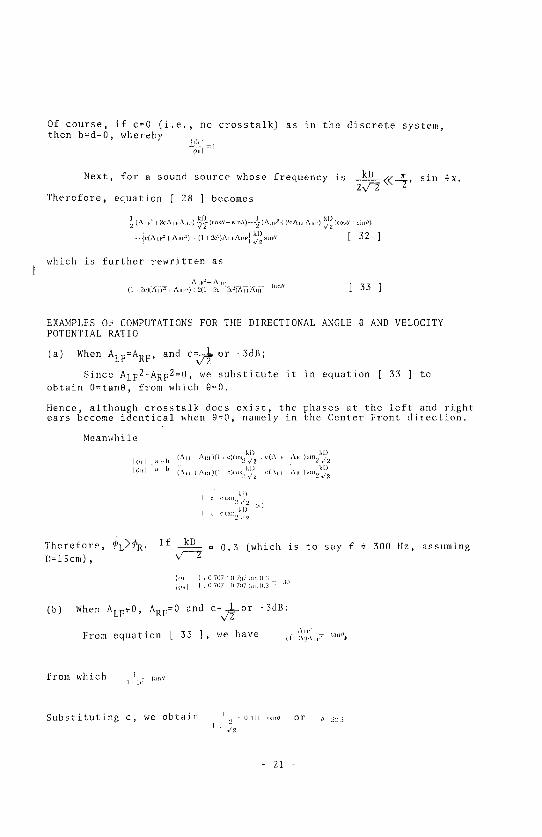
(2) A Matrix System Which Phase-Shifts the Rear Channel Signalsby 90 ° and 180 ° and Which Distributes the Crosstalk Asymmetrically.
Such a matrix system provides the output vectors as presentedin Fig. XI. The complex volume velocities emitted by the fourspeakers wi.l] then be
I,F ,t_(A_l' I cA.. jCAh,)
RF 4::(Am cAET_ I )cA,n)
IAI ,1= (AL. c\cc t ]CAll)
RB Izr (A,, i cA_ i jcAm )
As before, we first obtain the velocity potentials reaching theleft and right ears by substituting the abeve values Jn formu]as[ 4 ] and [ 5 ].
CA.... A,,,_ A.... ,\,./ ..... fi,V_-("'_" .... ,,>, _._,\.... x.,)
kl) kD
>sin, z2(cob// MnO) I c(All]; ,\1 )Mn,i z2((,os/J Mp/I)kl kl)
,l!c(At,l_iA.i)t.s,_ 2(co_Z_ sm0) c(/\.. Z\ll)C_S v2(Cc_ smU)
cAll)sm k,D2(/r),t]-- ,lIlf/)i(,'\tlt LAIn AE,i cai,,)(\,1
kI ....../:0 [ 36 ]> sm,, ,2 (;c_/!
and similarly,
,;1_ r (All _ '\., ,'\,1' c\_l,co_ _ 2(rcs _mU)
q _
.Al.i.Ai,i_.i.,:.?/..........._.,\.....\.._,.)%,m _
· kD sllllll ('(Alii: A i)l'()h k )2(i,oq// hlllll )) Ic(''\ t II_ e\]ll)('osZv_(c()sd ..
(A,; ,"\ ..... % ...... ,\,, ) _,,,:!kl) ( ............ )
m
p _
_,,......,,,,,,.......,,,_,..):%_,............_}_ [ z7 ]
Again, we assume a case whore only a 'front input signal'enters the Left Front and Right Front microphones.
Since ALB=Ai/B=O, substituting that relationship into equations[ 36 ] and [ 37 ], we have
k kI)
)[) IIjr(l _/\11 //
_tn2, 2 to_ sln'_ (L c).\l.. _' : z .in//)
kl) kl)
(,zXlt I qlll ' 2}_(,o_[/,, hill/I) \1 S 1, _ 2(t_SY Sm/]_r kI) kD
j_(] ch\{i _lq, _co%ll %]i1/I, (/ ()AiH NIH; kk ()'_[) %Ill/Y)
23 -

For the sake of simplicity, we put
) (1 c),\.l co_,, /2(_,,_/ Skil//) a
o\ ,ri ,2( ) ), All _m,2,(cos/}_mfl) bkD
](1 c;,\ ...... j_ 2,cos/' ...... ) (I :c)Aic, Sln,kl,)z( ............. ) c
[ c,,\,_ c_ k])2 (co_L'sm//) CALLC_S2_2d)[ , _// , Sin') d
Whereupon, equations [ 38 ] and [ 39 ] can be rewritten as
....._ ,,> j<,.d>'; [ 40 ]0, ' _ i(a
J_l'' <1)}0. , q(a_t>) 0(_ [ 41 ]
Consequently, the phase angles of these velocity potentialsfront the middle point between the ears, _I, and _R, are
d
_' t""' i, [ 42 ]It' d). ta. ia,h [43]
Since it is our fundamental assumption that the directional angleof the reproduced sound 5mage is determined when _],=_R,
c d (c d),,I, ,,b [44l
from which
_,, I,_l [ 4S ]
We now recall the abbreviations and expand the above equationto eventually derive
k {_, _?,V,, ,"A:,. } _,,k,,,,, (_,,.,....... ) _'5{0 ,)'\ .... '.\,., J
5HiI_ 2 [ ..... / sin/l) (I '?£ )'\[ ] '\Ill '111klJ_2 2( ,\1 i Alt[ .... kD_2 .... // [ 46 ]
On the other hand, the magnitudes of the velocity potentialsat the ears are given by
,. ,Ix"<" I,, ',, _/" [ 47 ]
,,;,' ,'\'/_' i,_,<_<1_' [ 48 ]
in which case, the ratio between 101,] and {</;Ri is
/ , d ;L h"j: x, ht }:/ _ d) _,t b_\ i ,t b
24

Naturally, if c=0 (i.e., no crosstalk) as in the discrete system,b=d=0, so
:!h I 16M
Furthermore, if the sound source frequency is within
x/_(_ --_, then sinx=x. Equation [ 46 ] can then be rewritten as
(I 'Jtq(At J': AI,m'i 2(I ' 2cQAM Alt[ trow
EXAMPLES OF COMPUTATIONS FOR THE DIRECTIONAL ANGLE 0 AND VELOCITYPOTENTIAL RATIO
(a) When ALF=Ap,F and c=._!_1or -3dB:xZT
Substituting those values in equation [ 50 ] yields -4=tan 0,
from which 0=3SO30 ', so that tho Center Front sound source appearsfrom a somewhat rightward direction in playback.
Assuming ,k_=0. 3, we compute the values of a and b to obtain_v _
,t Ic)7.\,, and /, o_:_{,,\,, , which we substitute in equation [ 31 ]to obtain the left-to-right velocity potential ratio at the ears:
,h a b i <_7 (_ L_6
lb) When ALF=0, ARF=0 and c=---!_1 or -3dB:
Substituting the values in equation [ 50 ] gives us =tan0,which ]n turn gives us 0=90 ° . The Left Front sound source there-fore appears in the straight leftward direction.
Assuming k_=0.3, a=l.63ALF and b=0.209AiF ,,, which are thensubstituted in equation [ 31 ] to determine the left-to-rightvelocity potential ratio at the ears:
:!;m: O77',hi
(c) When four microphones having cosine directional sensitivityare placed as shown in Fig. V to pick up a 'front input signal':
Following the same computing process as for the first typeof matrix, we eventually obtain from equation [ 33 ]:
'dLr,_l/'_tlli/' :It C_)s2//' (_)_II'slI]I ' I
<B_,,')d 2_).,_,,,' ,,,,,,:,, ,2 ' ...... [ S1 ]
- 25-

It is evident that the matrix system under review locates soundimages asymmetrically, and this fact is clearly disclosed inFig. XII where the preceding analysis is extended to cover theentire 360 degrees of directionality. Not only does it localize
sound images asymmetrically in both left-right and front-backrelations, but it mis]ocates the Center Front sound source.
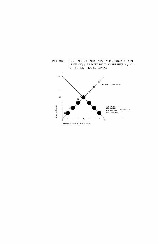
6. CONCLUSION
An experiment by T. Fujita (NIIK Technical Research Labora-tories) reveals that man's ability to recognize the directionalityof a sound source is accurate in ail directions when the sound
source is of a high frequency (see Fig. X]I).
However, for a sound source in the middle and iow frequencyrange, such ability deteriorates in the front-back direction (i.e.,the listener tends to mistake a front source for a back one), yethe is still ab]e to judge the left and right directionalities withaccuracy.
It was contended in the introduction of this paper (]) thatman discerns the directionality of a high-£requency sound sourceon account of the directional sensitivity of his ears, but that (2)he distinguishes that of a low~frequency sound source as a conse--quence of the phase difference his ears perceive.
Our theoretical analyses validate such contentions. Forinstance, if two sound sources are located symmetrically -- in thefront and back -- across the left-right ax]s, the phases of theresulting sound waves reachi_lg the left and right ears are identical,so that nlan is unable to distinguish between the front and backdirectional]ties. This is in keeping with the findings of the men_tioned experiment by Fujita (although tl_e frequency ranges consideredin the experiment and in this paper differ somewhat).
Thus, we define the directionality of a reproduced soundimage, in a four-channel system having a '2-2' speaker ?os[tien, asthe angle at wbicb the phases perceived by a listener sitting in thedead center coincide.
In the case of the discrete system, this directionality re-mains unchanged both in the live sound fie]d and Jn the reproducedsound field. This can be said of 4-2--4 matrix systems as well unlessthe inevitable crosstalk is phase-shifted.
Once the crosstalk is phase-shifted, however, it becomes im_possible to reproduce the original sound source directional]tiesexactly as they are. Nevertheless, a system that dSstri[mtes thecrosstalk symmetrically -- such as the Sansui QS regular matrixsystem -_ localizes sound images with correct left-right and front-back symmetry. Its drawback is that it tends to shrink the psyche-acoustic distance between the Left Front and Right Front speakers,
and between the Left Back and Right Back speakers.
26 -

In contrast, with a system that distributes the crosstalkasymmetrically and that employs asymmetrical phase shifts, soundimages are located asymmetrically and therefore tend to be mis-located.
As for the Sansui QS regular matrix system, the introductionof the Vario-Matrix technique into it permits us to obtain soundimage directionalities which are psycho-acoustically equivalent tothose of the discrete system. This was demonstrated in Part I ofthis paper.
27

REFERENCES
Part I
1. "Proposed Universa] Encoding Standards for Compatible Four-Channel Matrixing" by R. Itoh (Sansui Electric Co., Ltd.),presented at the 41st Audio Engineering Society Convention.
2. "The Sansui QS Coding System and a New Technique to Improveits Inter-Channel Separation Characteristic" by R. Itoh andSusumu Takahashi (Sansui Electric Co., Ltd.), presented atthe 42nd Audio Engineering Society Convention.
3. "Temporal Masking of Directional Information" by Masao Ebata,Toshio Sone and Tadamoto Nimura (Tohoku University), Reportsof the 1972 Spring Meeting, The Acoustical Society of Japan.
Part II
1. "Experiments on the Localization of Real Sound Sources in aHorizontal Plane" by T. Fujita (NHK Technical Research Labora-tories), June, 197-.
2. "Discrete-Matrix Multichannel Stereo" by D. Cooper (Universityof Illinois) and T. Shiga (Nippon Columbia Co., Ltd.), Journalof the Audio Engineering Society.
28

FIG. I. DIRECTIONALITY OF SOUNDSOURCE IN 2-SPEAKER PLAYBACK
Speaker1 Speaker2
X /\ //
X /k /
k /X /
\ /X
/k /
x /x /
L R
¢" ¢' ',l/
Speaker 1 Speaker 2 Speaker i Speaker 2
....../ j. ,Composite Wave Front
CompositeWaveFront \ '
a. Speakers 1 and 2 Producing b. Speakers 1 and 2 ProducingSame-Frequency, In-Phase Same-Frequency, Out-of-PhaseSounds of Different Levels Sounds of Same Levels

FIG. II. DEFINITION OF DIRECTIONAL ANGLE
FIG. III. IIOW TO DETERMINE DIRECTIONALITY OFREPRODUCED SOUND IMAGE
^ i^i n
x, .1 '
_SL Vn
t
_"' \.L.,_..ZJ'.D'
5/Directional Sensitivity of Ears

FIG. IV. LOCALIZATION O17 A SOUND SOURCE IMAGE
IN '2 - 2' SPEAKER POSITION
Speaker Speaker
LF RF
'4
/ I "_I '%.
Speaker /' I _, Speaker
t D I lib
FIG, V. PICK-UP OI,' A SOUND SOURGF, BY F()I, JR
MICROPIiONF, S WITI l COSINE DIRECTIONALSENSITIVITY IN '2 - 2' POSITION
__ Sensltlmty
I'
Directional SensltlvltV Directional Sensitivity
Xx.._ j "x Y- '"%
/ WFIG. VI. 1,OCALIZATION ()F A SOUND SOURCii
IN4AGE IN '2 - 2'
o
_At[_CA_[ *CAin) _ARFICAL_ CAI_
IF RF
/r
D
x,/
"x
/ ; _x____¢____
LB REI(AL8 ' CALF [ CARII) IA_*B, CAFII _CAtEII

FIG. VII. CHANGE INTOTAL ENERGY LF,VEL DUL?TO CROSSTALK WHEN IDENTICAL SIGNALS
EN_FER I.F ANti) RF
rIB10
9
8
7
g 6
® 5Ew
3
2
0 I q
-10 --20 _30dBCrosstalk
FIG. VIII. OUTPUT INI}ACH CHANNF, L AS DELIVERED
BY A ROTATIONAI,i.Y SYMMWI'RICAL
P[IASE-A MPLITUD]'; MATRIX
Aaf
t.... i"CAt_
CAm
_- _ AL_ CA.s
k[_ Acfl F_LI
CARU
CALF Ami

FIG. IX. CHANGE IN REPRODUCED DIRECTIONALITY DUE TO CROSSTALK
(WHEN USING MICROPI-IONES WIq'H COSINE DIRECTIONAL SEN-SITIVITY TO FEED IDENrI'ICAL SIGNALS INTO LF AND RF)
_ Directional Angle in Live Sound Field- 3dB -3dB
--20dR ] _45 ° --20dB/
40o. _40 ° ///
/
X\ / -co\ /
\\ ///
//
45 ° 40° 30 ° 20 ° 10° 0 -lO ° -20 ° -30 ° -40 ° -45 °
Directional Angle in Reproduced Sound Field
FIG. X, DIRECTIONAL CHARACTERISTIC OF A ROTATIONALLY
SYMMETRICAL PHASE-AMPLITUDE MATRIX (WHEN USING
MICROPHONES WITH COSINE DIRECTIONAL SENSITIVITY)
Directional Angle in Live Sound Field
135" -135
180' 135 ° 90 _ 45 _ -45 -90 -135 -180I I I
II Directional Angle in Reproduced Sound FieldI I
LB I RF RBI II I
LF II
I I
I RF
\Xx /
X //./
LB RB
FIG. XI. OUTPUT IN EACH CHANNEL AS DELIVERED
BY AN ASYMMETRICAL PHASE MATRIX
: Air
CAR_ ] CAaaCALe CALB · b ARt
/RB
ARa
lCALF CAR_ CAL_
CARt

FIG. XII. DIP,I£CTIONAI, CIIARACTI';RISTICOF AN ASYMMETRICAL PHASE MATRIX(WI I]';N USING MICROPI IONES WIT}t COSINE DIRECTIONA 1, SENSITIVITY)
Directional Angle in Live Sound Field180 180
135I 135
90904180 135 90 45 45 90 135 180
L'B ] I '1I 'Directional Angle in Reproduced RB
IIII\\\\ \ \ 'xx._'" '""" _ i LF-_ __ Sound Field,/'RF / / / / // //IllLB RB
HG. XII][. I)iP, I'iCTIONAL SENSITIVfTY OF HUMAN EARS
(SOUI_.Cb;: A RI'POP, T BY TAKASIII FUJITA, NI1K
T]';CII. 1_,1,2S. f_ABS, JAPAN)
18o
90
0
i t........./250 500Hz Band Nome800117 1 6kHz282 5_63kH ?
o 9o 18o
DlrectlofXal Arlgle of So_lrld Source