Characterisation of bending mechanics in uncured ... · Characterisation of bending mechanics in...
8
Characterisation of bending mechanics in uncured laminated materials using a modified Dynamic Mechanical Analysis S. Erland *1 , T. J. Dodwell * and R. Butler ** * College of Engineering, Mathematics and Physical Sciences, University of Exeter, Exeter, EX4 4QF, UK. ** Department of Mechanical Engineering, University of Bath, Bath, BA2 7AY, UK. Abstract Understanding the bending mechanics of uncured carbon fibre prepreg is vi- tal for modelling forming processes and the formation of out-of-plane wrinkling defects. This paper presents a modification of standard Dynamic Mechanical Analysis (DMA) to characterise the viscoelastic bending mechanics of uncured carbon fibre prepreg using Timoshenko beam theory. By post-processing DMA results, the analysis provides temperature and rate-dependent values of inter and intra-ply shear stiffness for a carbon fibre laminate and each individual ply with experimental results for AS4/8552 presented. The new methodology pro- vides a means to parametrise process models, and also gives an indication of optimal manufacturing conditions to enable defect-free forming and consolida- tion processes. Keywords: A. Prepreg; A. Laminates; B. Interface/interphase; C. Analytical modelling. 1. Introduction A popular method for manufacturing high value carbon fibre composites for aerospace is to form a flat laminate onto a male tool with the desired geometry. Heat and pressure are applied to consolidate and cure the material to the de- sired shape. During the forming [1], consolidation and curing processes [3, 4], the layers within the laminate shear internally (and therefore bend) relative to one another as the laminate conforms to desired shape [3]. The quality of the as-manufactured part intricately depends on the overall shearing mechanics of the laminate relative to geometry of the tool [5, 1]. If these shearing mechanisms are constrained a variety of defects can form, [6], in particular out-of-plane wrin- kling defects [3, 4] and bridging [7, 8]. Understanding the bending and internal 1 Corresponding author: [email protected] Preprint submitted to Composites Part A November 10, 2018 arXiv:1709.07940v1 [physics.app-ph] 18 Aug 2017
Transcript of Characterisation of bending mechanics in uncured ... · Characterisation of bending mechanics in...

Characterisation of bending mechanics in uncuredlaminated materials using a modified Dynamic
Mechanical Analysis
S. Erland*1, T. J. Dodwell* and R. Butler**
*College of Engineering, Mathematics and Physical Sciences, University of Exeter, Exeter,EX4 4QF, UK.
**Department of Mechanical Engineering, University of Bath, Bath, BA2 7AY, UK.
Abstract
Understanding the bending mechanics of uncured carbon fibre prepreg is vi-tal for modelling forming processes and the formation of out-of-plane wrinklingdefects. This paper presents a modification of standard Dynamic MechanicalAnalysis (DMA) to characterise the viscoelastic bending mechanics of uncuredcarbon fibre prepreg using Timoshenko beam theory. By post-processing DMAresults, the analysis provides temperature and rate-dependent values of interand intra-ply shear stiffness for a carbon fibre laminate and each individual plywith experimental results for AS4/8552 presented. The new methodology pro-vides a means to parametrise process models, and also gives an indication ofoptimal manufacturing conditions to enable defect-free forming and consolida-tion processes.
Keywords: A. Prepreg; A. Laminates; B. Interface/interphase; C. Analyticalmodelling.
1. Introduction
A popular method for manufacturing high value carbon fibre composites foraerospace is to form a flat laminate onto a male tool with the desired geometry.Heat and pressure are applied to consolidate and cure the material to the de-sired shape. During the forming [1], consolidation and curing processes [3, 4],the layers within the laminate shear internally (and therefore bend) relative toone another as the laminate conforms to desired shape [3]. The quality of theas-manufactured part intricately depends on the overall shearing mechanics ofthe laminate relative to geometry of the tool [5, 1]. If these shearing mechanismsare constrained a variety of defects can form, [6], in particular out-of-plane wrin-kling defects [3, 4] and bridging [7, 8]. Understanding the bending and internal
1Corresponding author: [email protected]
Preprint submitted to Composites Part A November 10, 2018
arX
iv:1
709.
0794
0v1
[ph
ysic
s.ap
p-ph
] 1
8 A
ug 2
017

shearing mechanics of uncured laminate and the dependence on manufacturingconditions (e.g. temperature, deformation rate) is important for manufacturingdefect-free components [6]. In particular a fundamental understanding of thesemechanics should inform composite process models and their input parameters(e.g. ANIFORM, PANFORM and Cosserat [2] which are computational mod-elling tools used early in the manufacturing design process.
Figure 1: (Left) Cross-sectional image of three uncured unidirectional plies of 8552/AS4 takenat 300x magnification. Distinct regions of fibre, resin and air can be seen, which contribute tothe material behaviour in very different ways when under the influence of heat, pressure anddeformation. (Right) Two scales of shear exist in a composite laminate, i.e. inter-ply shearbetween layers, and intra-ply shear within the layers themselves. The structure of stiff andweak layers results in asymmetric shear behaviour, i.e. σ12 6= σ21
A prepreg laminate is made up of fibrous layers separated by a resin richinterfaces, Fig. 1 (left). Two-scales of shearing occur when bending a laminate.Firstly, on the macro scale, the shear stiffness of the fibrous plies (intra-ply shearstiffness) is much higher than that of the interfaces (inter-ply shear stiffness).Consequently, as a laminate bends, most of the through-thickness shear strainlocalizes to the interface regions whilst the stiffer fibrous plies bend indepen-dently. The degree of independent ply bending depends on the relative intra-plyand inter-ply shear stiffness of a ply and interface respectively [2]. The secondscale of shear occurs at the ply scale. As a ply bends within the laminate, theshear stiffness parallel to the fibre is much greater than that in the transversedirection, and consequently the ply itself also shears through-thickness as itbends.
To understand the factors which affect the shearing mechanics of a lami-nate and ultimately build these mechanics into composite process models [2],we require an experimental methodology to characterise both intra and inter-plyshear behaviour. Inter-ply shear stiffness has been investigated in a number ofstudies [9, 10], in which it has been observed that an optimum forming tem-perature might be determined due to the transition from viscous to frictionalbehaviour as the resin is heated and redistributes within the laminate. Charac-terisation of the bending of individual plies and the intra-ply shear mechanismit generates is much less studied. The most common technique used to inves-tigate ply bending is the Peirce cantilever test [11], however this suffers from
2
a number of drawbacks. In general the problem with attempting to ascribe avalue of bending stiffness to a ply is that the derivation of this value requires theassumption of no through-thickness shear during ply bending (i.e. Engineer’sbending theory). Due to significant shear deformation, this assumptions leadsto a length dependent bending modulus [12].
In this short communication, the idea is to develop a methodology to charac-terise intra and inter-ply shear using a widely available experimental procedure.Previous experimental tests for inter-ply shear display a viscoelastic behaviourwhich is both rate and temperature dependent. A natural choice thereforeis Dynamic Mechanical Analysis (DMA), in which materials are readily char-acterised over different rates of deformation and a sweep of temperatures. Bypost-processing standard DMA results using Timoshenko beam theory the anal-ysis provides temperature and rate-dependent values for a inter and intra-plyshear, which are parametrised by a simple heuristic model. Experimental resultsare presented for single ply and small 0◦ laminates for AS4/8552. The commu-nication concludes with a brief discussion of the results in context of choices inmanufacturing process design, process modelling and further extensions usingzig-zag theory [13] to account for the influence of angled plies and more complexstacking sequences.
2. A Modified Approach to Dynamic Mechanical Analysis
2.1. Experimental Procedure
The single cantilever mode is chosen for DMA in which a short beam sampleof length `, thickness h and breath b (Fig 2) is fixed at one end, whilst at the‘free’ end rotations are constrained. Samples are mounted with quick curingpolyurethane tabs (Fig. 2) to ensure the boundary conditions are maintainedduring a test. The polyurethane is demoldable within 30 minutes, and mixedwith milled carbon fibre to ensure it is sufficiently stiff and thermally stable. Thesample length ` is measured between the points at which the carbon fibre sampleenters the resin tab. The free end is vertically displaced by w = wmax sin(ωt)and the required cyclic force P = Pmax sin(ωt+δ) and phase lag δ are measured.The quantity tan δ is a measure of the balance between elastic (tan δ = 0) andviscous (tan δ = 1) components.
The maximum displacement wmax = 0.05mm is chosen to ensure that theshear strain invoked is small. The temperature ramp is set to 3◦C per minute,with the maximum temperature investigated for this material (8552/AS4) being130◦C, well below the cross-link initiation temperature of 154◦C. Coupled withthe relatively rapid heating rate this eliminates the risk of the sample curingduring testing.
2.2. Bending of a ply - Intra-ply shear
To characterise intra-ply shear (i.e. within an individual ply), we considera single ply in bending. Using Timoshenko beam theory [14], the deformation
3
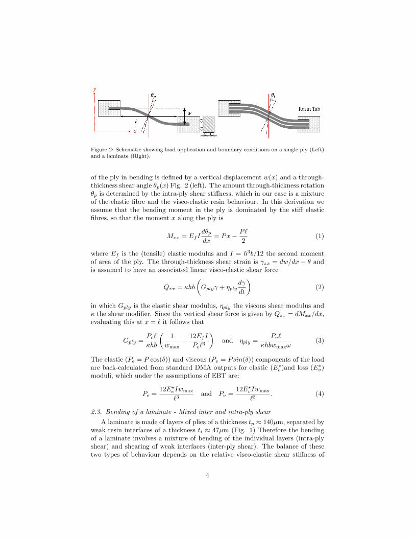
Figure 2: Schematic showing load application and boundary conditions on a single ply (Left)and a laminate (Right).
of the ply in bending is defined by a vertical displacement w(x) and a through-thickness shear angle θp(x) Fig. 2 (left). The amount through-thickness rotationθp is determined by the intra-ply shear stiffness, which in our case is a mixtureof the elastic fibre and the visco-elastic resin behaviour. In this derivation weassume that the bending moment in the ply is dominated by the stiff elasticfibres, so that the moment x along the ply is
Mxx = EfIdθpdx
= Px− P`
2(1)
where Ef is the (tensile) elastic modulus and I = h3b/12 the second momentof area of the ply. The through-thickness shear strain is γzx = dw/dx − θ andis assumed to have an associated linear visco-elastic shear force
Qzx = κhb
(Gplyγ + ηply
dγ
dt
)(2)
in which Gply is the elastic shear modulus, ηply the viscous shear modulus andκ the shear modifier. Since the vertical shear force is given by Qzx = dMxx/dx,evaluating this at x = ` it follows that
Gply =Pe`
κhb
(1
wmax− 12EfI
Pe`3
)and ηply =
Pv`
κhbwmaxω(3)
The elastic (Pe = P cos(δ)) and viscous (Pv = Psin(δ)) components of the loadare back-calculated from standard DMA outputs for elastic (E∗
e )and loss (E∗v )
moduli, which under the assumptions of EBT are:
Pe =12E?e Iwmax
`3and Pv =
12E?vIwmax
`3. (4)
2.3. Bending of a laminate - Mixed inter and intra-ply shear
A laminate is made of layers of plies of a thickness tp ≈ 140µm, separated byweak resin interfaces of a thickness ti ≈ 47µm (Fig. 1) Therefore the bendingof a laminate involves a mixture of bending of the individual layers (intra-plyshear) and shearing of weak interfaces (inter-ply shear). The balance of thesetwo types of behaviour depends on the relative visco-elastic shear stiffness of
4
inter and intra-ply shear. The through-thickness shear stiffness of the completelaminate (Glam and ηlam) will be dominated by the weaker regions (the inter-faces), therefore the shear response can be consider to be multiple shear-springsin series such that:
1
Glam=αplyGply
+αintGint
and1
ηlam=αplyηply
+αintηint
(5)
where Gint and ηint are the elastic and viscous inter-ply shear modulus respec-tively, and αint and αply are the fractions of the interface and the ply regionscontributions to the thickness of the whole laminate. Experimental values areobtained for Glam and ηlam by repeating the same DMA analysis as described inSec. 2.2, but using a laminated sample (Fig. 2) and deriving identical equationsas (3) but with different sample dimensions. Given that we know the intra-plyshear moduli Gply and ηply from the single ply analysis, we can rearrange (5)to calculate the intra-ply shear stiffness
Gint =αintGlamGplyGply − αplyGlam
and ηint =αintηlamηplyηply − αplyηlam
. (6)
3. Results
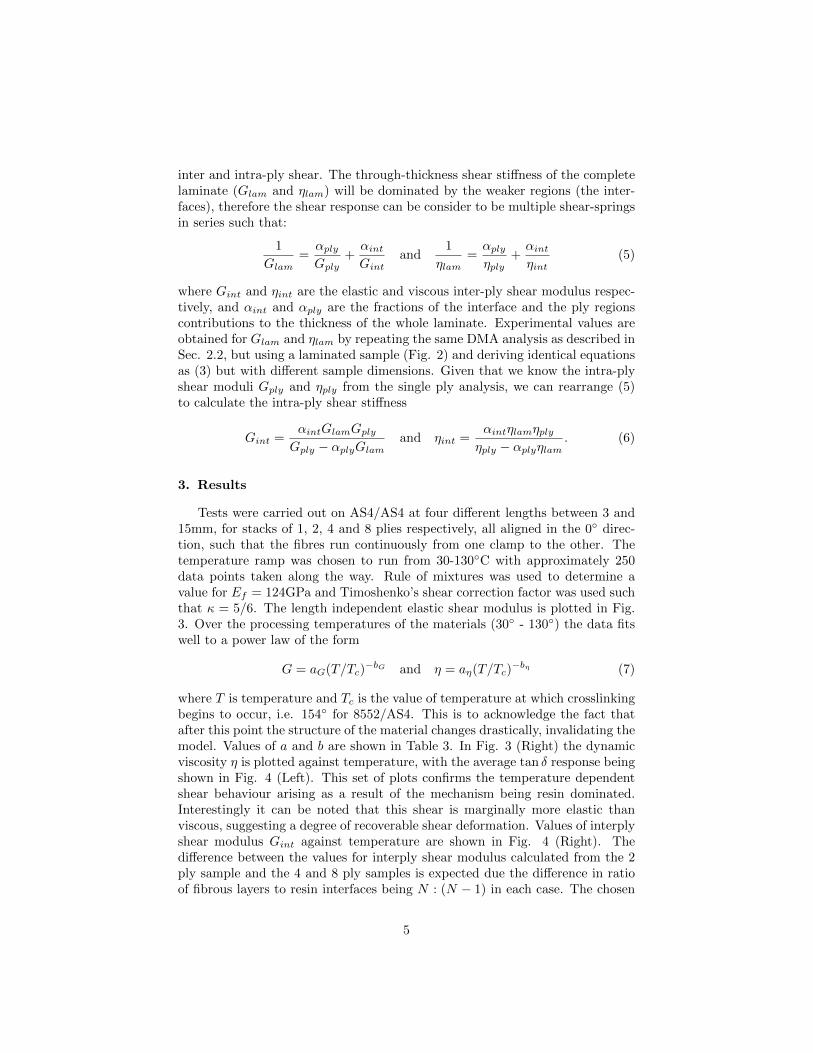
Tests were carried out on AS4/AS4 at four different lengths between 3 and15mm, for stacks of 1, 2, 4 and 8 plies respectively, all aligned in the 0◦ direc-tion, such that the fibres run continuously from one clamp to the other. Thetemperature ramp was chosen to run from 30-130◦C with approximately 250data points taken along the way. Rule of mixtures was used to determine avalue for Ef = 124GPa and Timoshenko’s shear correction factor was used suchthat κ = 5/6. The length independent elastic shear modulus is plotted in Fig.3. Over the processing temperatures of the materials (30◦ - 130◦) the data fitswell to a power law of the form
G = aG(T/Tc)−bG and η = aη(T/Tc)
−bη (7)
where T is temperature and Tc is the value of temperature at which crosslinkingbegins to occur, i.e. 154◦ for 8552/AS4. This is to acknowledge the fact thatafter this point the structure of the material changes drastically, invalidating themodel. Values of a and b are shown in Table 3. In Fig. 3 (Right) the dynamicviscosity η is plotted against temperature, with the average tan δ response beingshown in Fig. 4 (Left). This set of plots confirms the temperature dependentshear behaviour arising as a result of the mechanism being resin dominated.Interestingly it can be noted that this shear is marginally more elastic thanviscous, suggesting a degree of recoverable shear deformation. Values of interplyshear modulus Gint against temperature are shown in Fig. 4 (Right). Thedifference between the values for interply shear modulus calculated from the 2ply sample and the 4 and 8 ply samples is expected due the difference in ratioof fibrous layers to resin interfaces being N : (N − 1) in each case. The chosen
5
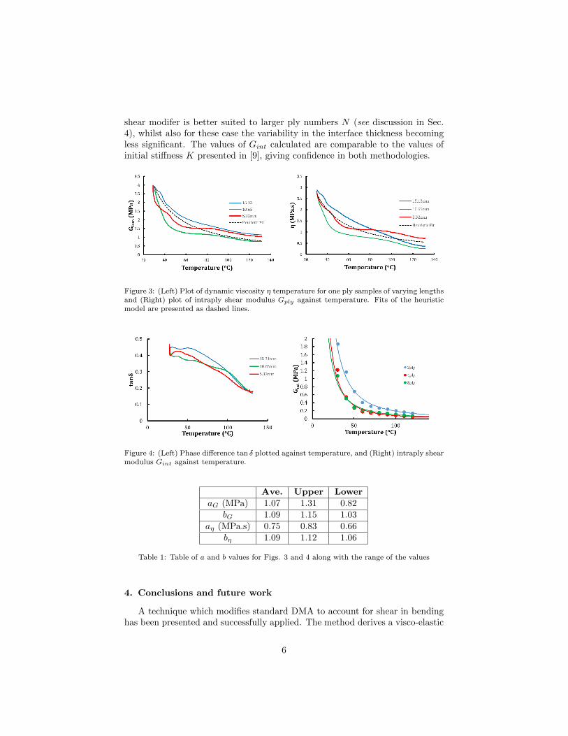
shear modifer is better suited to larger ply numbers N (see discussion in Sec.4), whilst also for these case the variability in the interface thickness becomingless significant. The values of Gint calculated are comparable to the values ofinitial stiffness K presented in [9], giving confidence in both methodologies.
Figure 3: (Left) Plot of dynamic viscosity η temperature for one ply samples of varying lengthsand (Right) plot of intraply shear modulus Gply against temperature. Fits of the heuristicmodel are presented as dashed lines.
Figure 4: (Left) Phase difference tan δ plotted against temperature, and (Right) intraply shearmodulus Gint against temperature.
Ave. Upper LoweraG (MPa) 1.07 1.31 0.82
bG 1.09 1.15 1.03aη (MPa.s) 0.75 0.83 0.66
bη 1.09 1.12 1.06
Table 1: Table of a and b values for Figs. 3 and 4 along with the range of the values
4. Conclusions and future work
A technique which modifies standard DMA to account for shear in bendinghas been presented and successfully applied. The method derives a visco-elastic
6

Timoshenko beam theory to derive an elastic shear modulus and dynamic vis-cosity which capture the contribution of through thickness shear in bending.The results highlight the benefits of DMA as a test platform, showing good re-peatability and accuracy whilst being easy to set up and run. Fitting the datato a simple heuristic equation greatly improves the ease with which the datamight be integrated into process models. From the results presented it can beobserved that a small increase in temperature greatly alters the shear character-istics of uncured carbon fibre prepregs, with a significant reduction after 50◦C(for this particular material). From [9] this would suggest improved formabil-ity, however we can now see that this would also mean a reduction in effectivebending stiffness leaving the individual plies vulnerable to buckling under form-ing induced loads [3]. It is therefore necessary to find some trade off betweenminimising inter-ply shear stiffness, whilst maintaining sufficient intra-ply shearstiffness to prevent wrinkling. Inter-ply shear results (Gint) are comparable withvalues of initial shear stiffness (K) as given by the heuristic model derived in[9], which, using a strain rate of 0.017s−1 as per the DMA methodology, pro-vides an initial shear stiffness K of 0.309MPa at 70◦C, versus the experimentalvalue of 0.211MPa from this paper. There are two key differences in the twostudies which account for this discrepancy. Firstly, experimental values in [9]are fitted to a more complex non-linear viscoelastic model, which has a morecomplex dependency on strain rate, and secondly, the tests conducted in [9] aresubjected to an overburden pressure, forcing the fibres in the adjacent plies tointeract. The small difference in values is therefore due to a difference in bothmodel fitting and experimental process. A key area for further improvement isto determine the correct shear modifier. This work uses the Timoshenko valueof κ, which assumes a uniform shear distribution over the thickness of the sam-ple, and while this is reasonable for a single ply, in which there exist many thin‘layers’ in the form of individual fibres and resin interfaces, it is not suited tothin laminates. This is due to the large mismatch in shear stiffness for a fibrouslayer and a resin layer, resulting in a non-uniform shear distribution. Futurework will focus on using the layerwise shear distribution offered by Zigzag the-ory [13] to generalise the calculation of κ for general laminates. The applicationof pressure to the sample during testing will also be investigated in order tobetter replicate the forming conditions encountered in industry, and improvethe comparison between this work and that presented in [9].
Acknowledgements
We would like acknowledge support from the EPSRC funded ADAPT projectbetween Exeter and Bath (EP/N024508/1 & EP/N024354/1).
References
References
[1] J. Sjolander, P. Hallander and M. Akermo. Forming induced wrinkling ofcomposite laminates : A numerical study on wrinkling mechanisms. Com-
7

posites. Part A, 2016. 81:41-51.
[2] T. J. Dodwell. Internal wrinkling instabilities in layered media, Philos. Mag,2015. 95:3225-3243.
[3] T.J. Dodwell, R.Butler and G. W. Hunt. Out-of-plane ply wrinkling de-fect during consolidation over an external radius, Composites Science andTechnology 2014. 105:151-159.
[4] S. R. Hallett, J. P. H. Belnoue, O. J. Nixon-Pearson, T. Mesogitis, J. Kratz,D. S. Ivanov and K. D Potter. Understanding and prediction of fibre wavinessdefect generation. In Proceedings of the American Society for Composites -31st Technical Conference, 2016, Vancouver
[5] M. W. D. Nielsen, K. J. Johnson, A. T. Rhead and R. Butler. Laminate de-sign for optimised in-plane performance and ease of manufacture. CompositeStructures 2017. DOI: https://doi.org/10.1016/j.compstruct.2017.06.061
[6] K. Potter. Understanding the origins of defects and variability in compos-ites manufacture, 17th International Conference on Composite Materials,Edinburgh, July 2009.
[7] T. A. Fletcher, R. Butler and T. J. Dodwell. Anti-symmetric laminatesfor improved consolidation and reduced warp of tapered C-sections, Ad-vanced Manufacturing: Polymer and Composites Science, 2015. DOI:http://dx.doi.org/10.1179/2055035914Y.0000000010
[8] J. S. Lightfoot, M. R. Wisnom and K. Potter. A new mechanism for theformation of ply wrinkles due to shear between plies, Composites, Part A2013. 49:139-147.
[9] S. Erland, T. J. Dodwell and R. Butler. Characterisation of inter-ply shearin uncured carbon fibre pre-preg, Composites Part A, 2015. 77:210-218
[10] Y. R. Larberg and M. Akermo. On the interply friction of different gener-ations of carbon/epoxy prepreg system, Composites: Part A 2011. 42:1067-1074.
[11] B. Liang, N. Hamila, M. Peillon and P. Boisse. Analysis of thermoplas-tic prepreg bending stiffness during manufacturing and of its influence onwrinkling simulations, Composites Part A 2014. 67:111-122.
[12] S. Erland Characterisation of uncured carbon fibre composites, Universityof Bath, 2017, PhD Thesis.
[13] A. Tessler. A refined zizag beam theory for composite sandwich beams,Journal of Composite Materials, 2009. 43:1051-1081.
[14] S. P. Timoshenko and J. N. Goodier. Theory of elasticity, London :McGraw-Hill 3rd ed, 1970.
8