CHAPTER THREE TECHNICAL SKETCHING - Davis … points, lines, angled lines, arcs, ... sketching is a...
34
CHAPTER THREE TECHNICAL SKETCHING OBJECTIVES After studying the material in this chapter, you should be able to: 1. Define vertex, edge, plane, surface, and solid. 2. Identify four types of surfaces. 3. Identify five regular solids . 4. Draw points, lines, angled lines, arcs, circles, and ellipses. S. Apply techniques that aid in creating legible well-proportioned freehand sketches. 6. Apply techniques to draw irregular curves. 7. Create a single view sketch. 8. Create an oblique sketch. 9. Create a one-paint perspective sketch. 10. Create an isometric sketch of an object.
Transcript of CHAPTER THREE TECHNICAL SKETCHING - Davis … points, lines, angled lines, arcs, ... sketching is a...

CHAPTER THREE
TECHNICAL SKETCHING
OBJECTIVES
After studying the material in this chapter, you should be able to:
1. Define vertex, edge, plane, surface, and solid.
2. Identify four types of surfaces.
3. Identify five regular solids .
4. Draw points, lines, angled lines, arcs, circles, and ellipses.
S. Apply techniques that aid in creating legible well-proportioned
freehand sketches .
6. Apply techniques to draw irregular curves.
7. Create a single view sketch.
8. Create an oblique sketch.
9. Create a one-paint perspective sketch.
10. Create an isometric sketch of an object.

59 T EC H N I CAL SK ETC H I N G
'f\.tT :sPLiT
UFr~/c£ / CrNJ&f2 \ \
Shaded sketch showing details of wire placement. Courtesy of Quantum Design.
OVERVIEW
The ability to envision objects in three dimensions is
one of the most important skills for scientists, design
ers, engineers, and technicians. Learning to visualize
objects in space, to use the constructive imagination,
is something you can learn by studying technical
drawing. People who are extraordinarily creative often
possess outstanding ability to visualize , but with prac
tice anyone can improve their ability.
In addition to developing spatial thinking skills,
sketching is a valuable tool that allows you to quickly
and accurately communicate your ideas. During the
development stage of an idea , a picture is often worth
a thousand words.
Sketching is also an efficient way to plan your
drawing and record notes needed to create a complex
object. When you sketch basic ideas ahead of time ,
you can often complete a final CAD drawing sooner
and with fewer errors. Using good technique makes
sketching faster, easier, and more legible .
Search the following Web sites for platonic solids (wikipedia, korthalsaltes), convex shapes (ibiblio), and octahedrons (korthalsaltes):
• http:/ /en.wikipedia.org/wiki/Platonic_solid • http://ibiblio .org /e-notes/3Dapp /Convex .htm • http:/ /www.korthalsaltes.com /platonic_sol ids_pictures.
html • http: //www.korthalsaltes.com/octahed ron.html

60 C HAP T E R 3 TEe H N I CAL S K ETC H I N G
These complex surface models were created using 3D CAD. Courtesy of Professor Richard Palais, University of California, Irvine, and Luc Benard.
Sketches and drawings are used to communicate or reco rd ideas about the shape of three-dimensional objec ts. Before starting to sketch, it helps to develop a voca bulary for understanding and dis(a) cussing three-dimensional shapes.
Three-dimensional ligures are referred to as solids. Solids are bounded by the surfaces that contain them. These surfaces can be one of the following four types :
• Planar (b) • Single-curved
• Double-curved • Warped
Regardless of how complex a solid may be, it is composed of combinations of these basic types of surfaces . Figure 3.1 shows examples of the four basic types of surfaces.
(c)
UNDERSTANDING SOLID OBJECTS Types of Solids Polyhedra Solids that are bounded by plane surfaces are called polyhedra (Figures 3.2-3.4). These planar surfaces are also referred to as faces of the object. A polygon is a planar area that is enclo sed by straight lines .
Regular Polyhedra If the faces of a solid are equal regular polygon s it is called a regular polyhedron. There are five regular polyh edra: the tetrahedron, hexahedron, octahedron , dodecahedron, and icosahedron (Figure 3.2).
Tetrahedron Hexahedron Octah edron Dodecahedron Icosahedron (4 triangles) (cube) (8 trian gles) (12 pentagons) (20 tr iangles)
(d)
3.1 Types of Surfaces 3.2 Regular Polyhedra

61 I
TECHN ICAL SKETCHING
Prisms A prism has two bases. which are para llel eq ua l po lygons, and three or more addi tiona l faces , which are parallelog ram s (Figure 3.3) . A triangular prism has a triangular base: a rectangular prism has rectangular bases: and so on. (If a prism 's bases happen to be paralle lograms, the prism is a ca lled a paral lelepiped . a word rarely heard in everyday conversa tion.)
A light pri sm has faces and lateral (side) edges that are perpendicular to the bases; an ohliq ue prism has faces and lateral edges that are ang led to the bases. If one end is cut off to form an end that is not parall el to the bases, the prism is sa id to be truncated (a wo rd which simply means "s hor tened by having a part cut off").
Pyramids A pyramid has a polygon for a base and triangul ar lateral faces which intersec t at a co mmon point ca lled the vertex (Figure 3.4) . T he line from the cent er o f the hase to the ver tex is ca lled the axis. If the axi s is perp end icul ar to the base, the pyramid is called a right pyra mid; othe rwise it is an oblique pyram id. A tri angular pyramid has a triangular base: a sq uare pyramid has a square base; and so on . If a portion nea r the vertex has been cut off, the pyra mid is truncated , or it is refe rred to as ufrustum.
Cylinders A cylinder has a single-curved ex terior surface (Figure 3.5). You can think of a cy linder as being formed by taking a straight line and mov ing it in a ci rcular pat h to enclose a volume. Each position of this imaginary stra ight line in its path around the axis is ca lled an element of the cy linder.
Cones A cone has a sing le-curved ex terior surface (F igure 3.6). You can think of it as be ing formed by movin g one end of a straight line aro und a circle while keeping the other end fi xed at a point, the vertex of the co ne . An clem ent of the co ne is any position of this imagin ary straight line .
Spheres A sphere has a double-cu rved exterior surface (Figure 3.7). You ca n think of it as be ing form ed by revolving a ci rcle about one of its d iameters, somewhat like spinning a coin. The poles of the sphe re arc the po ints at the top and bottom of the sphe re that wo uld not move wh ile it was spinning. The axis of the sphere is the term for the line between its poles.
Tori A torus is shaped like a do ughnut (Figure 3.8). Its bou ndary surface is do ub le-curved. You can think of it as bei ng for med by revolving a ci rcle (or other curve) around an ax is that pos itioncd away fro m (outside) the curve.
Ellipsoids An oblate or pro late ellipsoid is shaped like an egg (Fig ure 3.9) . You ca n think of it as form ed by revolvin g an e llipse about its min or or major axis, respectively.
Right square
Right triangular
Right circular Oblique circular (frustum) (truncated)
Torus
3.8 Torus
Prolate Ellipsoid
Right rectangular
Right pentagonal
Oblique rectangular
Oblique hexagonal
3.3 Right Prisms and Oblique Prisms
Right Right square Oblique rectangular (truncated) pentagonal
3.4 Pyramids
Right Oblique circular circular
3.5 Cylinder and Oblique Cylinder
Rig ht circular
3.6 Cones
Sphere
3.7 Sphere
Oblate Ellipsoid
3.9 Ellipsoids

3.10 Identifying Essential Shapes
3.11 Using Construction Lines
UNDERSTANDING SKETCHING TECHNIQUES
Analyzing Complex Objects The ability to break down complex shapes into simpler geometric primitives is an essential skill for sketching and modeling objects.
Before you begin to draw the outline of an object, con sider its overall shape and the relationships between its parts. Construction lines can help you preserve the overall dimensions of the ohject as you sketch.
Bear in mind that you should be thinking in terms of basic shapes whether you are sketching by hand or using a CAD program. Since basic curves and straight lines are the basi s of many of the objects that people create, practice in creating the basic elements of a drawing will help you sketch with ease.
Essential Shapes Look for the essential shapes of objects. If you were to make a clay model of an object, what basic shape would you start with? A ball? A box'?
Try squinting your eyes and looking at familiar objects, Do you see their shape as a rectangle? A circle '? What other basic shapes do you notic e when you look at obje cts this way?
Think about breaking down more complex ohjects into their simpler geometric shapes as shown in Figure 3.10. You can block in these shapes using construction lines to show their relationships to one another. Then add details. continuing to pay attention to the spatial relationships between them .
Construction Lines Artists often begin a sketch by mocking in light guidelines to help them preserve basic shapes and proportions. In technical drawing these are called construction lines (Figure 3.1 I).
It is often helpful to begin a sketch by describing the object's main shapes with construction lines. taking some care to accurately represent the relative size and placement of features .
Use the basic shapes as a guide to place key features. Then use those maiu features as a "reference map" to place smaller details. For example, the sixth fret line is about halfway up the rectangular guitar neck.
Throughout this chapter you will use light construction lines to draw circles. arcs, and ellipses. Section 3.7 discusses the process of estimating and maintaining the proportions of an obje ct in further detail.

63 TEe H N I CAL 5 K ETC H I N G
Contours and Negative Space Th e contours of an object are the main outlines that separate it from the surrounding space . On e way to think about tbe con tours of objec ts is to look at the co ntras t between the positi ve and negativ e space , Posit ive space is the space occ upied by the objec t. Negative space is the unoccupied space aro und it.
In Figure 3.12 the space occ upie d by the contour of a pair of sc isso rs is sho wn. Note how you can identify specific shapes by looking at the negative space . Th e indiv idua l shapes that mak e up the negati ve space are shown in different colors to make them easier for you to see. Some people sketch more accurately whe n they try to dr aw the negat ive space that surrounds the object.
Contour Negative space Shapes shown
3.12 Negative Space . 2007 jupiterimages Corporation.
,--- TIP --------------------------------,
Practice drawing contours Try sketching the negative sp aces that def ine the shape of a chair. Look at each space as an individ ual shape. What is the shape of the space between the legs? What is the shape of the space between the rungs and the seat?
Make a sketch of a chair, paying careful attention to sketching the negative spaces of the chair as they really appear. The positive and negative spaces should add up to define the chai r.
Ifyou have difficulty, make corrections to your sketch by defining the positive shapes and then check to see if the negative shapes match .
An 8.5-by-11 sheet of Plexiglas (available at most glass stores) is an excellent tool for de veloping sketching ability. Using a dry erase marker, hold the Plexiglas up in front of an object and trace its contours on the Plexiglas. If you don't move, the outl ine should match the object 's outl ine exactly. Lower the Plexiglas and look at the or ientation of the lines . Are they what you expected?
Try looking at the object and drawing the sketch with the Plexiqlas laying on your desktop or knees . Then raise it up and see if your drawing matches the object.
To develop sketching ability, try drawing everyday objects like your toaster, printer, or lamp, as well as exterior and interior views of buildings and eq uipment.
-Firsttry Examine negative shapes Note differences More accurate proportions
Reprinted by permission of Pearson Education Inc. Upper Saddle River, Nj.

64 CHAPTER 3 TECHNICAL SKETCHING
3.13 Rubber Stamp
3.14 Hatching. Reprinted by permission of Pearson Education, Inc., Upper Saddle River, N}.
3 .15 Stippling. Reprinted by permission of Pearson Education, Inc., Upper Saddle River, N}.
Viewpoint As you sketch objects, keep in mind that you want to maintain a consistent viewpoint like a camera does. This is easier when you are sketching a picture from a book, because you can't move around the object. When you move, you see a different view of the object, depending on where you stand.
Sometimes people have difficulty sketching hecause they want to show parts of the object that cannot really be seen from a single viewpoint. For example, know ing that the handl e of the rubber stamp in Figure 3.13 appears circular from the top, you may be tempted to show it as round, even though it may appear elliptical from your viewpoint.
When you are sketching an object pictorially, temporarily set aside your knowledge of the shapes the object is actually made of and carefully examine the shapes you see from a single , static viewpoint. In this type of sketching, instead of trying to envision the object as it is, try only to see it as it looks.
Shading Adding shading to your sketch can give it a more reali stic appearance because it represents the way the actual object would reflect light. Shading doesn't mean "coloring in." You may only want to shade the most prominently shadowed areas. First identify the darkest and lightest areas on an object. If you want , you can shade various middle tones , placed exactly as they look on the object.
In some ways, shading is like doing a drawing within a drawing, because it is a matter of identifying shapes. When you arc shading, instead of identifying the shapes of the object's contours, you are identifying the shape and relative darkness of the shadows.
Hatching lines , shown in Figure 3.14 , and stippling, shown in Figure 3.15, are commonly used methods to add shading because they are easier to reproduce with a photocopier than continuous tone pencil shading. In the illustration you can see that shadowed areas are simply darkened by adding more hatching lines or stippling dots .
It is not uncommon for people to draw outlines by hand and add digital shaded fills to a scan of the outline. Marker shading is another popular shading method (Figure 3.16) .
Regardless of how you apply shading, darken the outline to define the shape clearly and boldly. Remember that when you are communicating hy using a sketch, its subject should be clear. To make the subject-in this case. a rubber stamp- -dear, make it stand out with thick bold contour lines .
.:
3.16 Marker Shading in a Concept Sketch. Courtesy of Douglas Wintin.

65
Edges and Vertices
Edges An edge of the solid is formed where two surfaces intersect. Edges are repre sent ed in drawings by visible or hidd en lines (Figure 3.17).
Vertices A vertex (plural, vertices) of a so lid is form ed where three or more surfaces intersect. The end of an edge is a vertex . The se vertices or "points" arc very useful in defining the solid object featu re locati ons that you will sketch (Figure 3. 17).
Points and Lines A point is used to repre sent a location in space, but have no width. height, or depth (Figure 3.12). A point in a drawing is represented by the intersection of two lines (Figure 3.18a), by a short crossbar on a line (Figure 3. 18h), or by a small cros s (Figure 3. 1Sc), Do not represent point s by simple dot s on the paper. Thi s makes the drawing look "blobby' and is not as accurate.
A line is used in drawings to represent the edge of a solid object. A straight line is the shor test distance betw een two point s and is commonly referred to simply as a " line." If the line is indefinite in extent , in a drawing the length is a matter of convenience, and the endpoints are not mark ed (Figure 3. 19a) . If the endpoints of the line are significant. they are mark ed by small drawn cross bars (Figure 3.19b). Other common terms are illu strated in Figures 3.19c to 3. 19i. Either straight lines or
(a) (b) (c) (d)
TEe H N I CAL SK ETC H I N G
3.17 Edges and Vertices of a Solid
( paint C point \;" POint
~X + (a) (b) (c)
3.18 Showing Points
curved lines are parallel if the shortest distance between them remains con stant. The co mmon symbo l for parallel lines is I I, and for perp endi cular lines it is ..L Two perpendicular lines may be marked with a "box" as shown in Figure 3.19g. Such symbols may be used on sketches, but not on production drawings.
Horizontal line
(f) (9) (h) (I)
3.19 Showing Lines

When minutes alone are indicated. the number of minutes
0 should be preceded by 0 0, as in 0° 20'.
Less The different kinds of angles are illustrated in Figure 3.20. ........ than
( 1800\ 90° Two angl es are complementary if they total 90 ° (Figure 3.200,I ~Ot , and are supplementary if they total 1800 (Figure 3.20g). I
Complete circle Straight angle Right angle Accute angle In sketching, most angles can be estimated. Use a protrac
(a) (b) (c) (d) tor if nece ssary when drawing odd angles.
Mo re than
~7~~90°, _~o}~B
t Obtuse angle Complementary Supplementary
angles angles (e) (f ) (g)
3.20 Showing Angles
Angles An angle is form ed by two intersecting lines . A common symbol for angle is L.
There are 360 degrees (3600 ) in a full circl e, as shown
in Figure 3.20a. A degree is divided into 60 minutes (60'), and a minute is divided into 60 seconds (60"). The angl e value 37 0 26 ' 10" is read 37 degrees. 26 minutes , and 10 seconds.
Drawings and Sketches The following are important skill s to keep in mind for sketches and drawings:
I. Accuracy. No drawing is useful unless it shows the information cor rectly.
2. Speed. Time is money in indu stry. Work smarter and Jearn to use techniques to speed up your sketching and CAD drawings while still producing neat accurate results.
3. Legibility. A drawing is a mean s of communication to othe rs, and it must be clear and legible . Give attention to details. Things that may seem pick y and small as you are drawing may be significant and save money or even live s when the product is built.
4. Neatness. If a drawing is to be accurate and legible, it must also be clean .
ACCURACY COUNTS
Accuracy and legibility in drawings is serious business, as is demonstrated in this article
~.
from New Scientist Magazine about the October 2004 Genesis dizzy probe crash.
Courtesy of NASA.
Dizzy probe crash You'd think that by now, NASA should be able to tell up from down . Not so in the case of their Genesis space capsule, which crashed into the desert in Utah instead of parachuting gently down so that helicopter stunt pilot s could pluck it to safety.
Since its launch in August 200 I, [he capsule had been collecting precious particles from the solar wind that would have told us something abont the composition of the so lar system.
But afte r re-entering Earth 's atmosphere on Sept ember 8, Gen esis plunged into the ground and much of its payload was lost.
On October 15. investigators released their prel iminary conclusion s, blaming the crash on "a design error that involves the orientation of gravityswitch devices." Huh?
The four small cylindrical switches were designed to sense the re-entry and trigger the parachute. But they were
drawn upside down in Lockheed Martin's technical drawings, so they were installed upside down-although NASA' s Micha el Ryschkewitsch , who led the investigation, is reluctant to use those exact words. The switches neve r detected the re-entry. Similar devices are installed on another sample-collecting mission called Stardust. Ryschkewitsch believes these are the right way up.
Courtesy of New Scientist magazine.

Freehand Sketching
l--1.25 II
2.50 I I J. I .l.- L....f- - -- - - f-J"<,
r 2 .00
Freehand sketches are a helpful way to organize your thoughts and record ideas. They provide a quick. low-cost way to explore various solutions to design problems so that the hest choices can be made. Investing too much time in creatin g a detailed layout before expl oring your options through sketches can be costly.
The degree of preci sion needed in a given sketch depend s on its use. Quick sketches to supplement verbal descriptions may be rough and incomplete. Sketches can be used to convey important and precise information when they are clearly drawn and annotated.
Freehand sketching requires only pencil, pape r, and eraser. Master the techniques in this chapter for showing quick single view. oblique, perspective, and isometric drawings using good freehand line technique and you will possess a valuable tool for communicating your ideas .
The term freehand sketch doe s not mean a sloppy draw ing. As shown in Figure 3.21 , a freehand sketch shows attention to proportion, clarity, and correct line width s. Figu re 3.22 shows an as-built drawing with corrected items sketched on the printed CAD dra wing.
~
CD "'~
Q
CJ CJ
I-'fll
CJ CJ
o
CI c:J
j
/ 0 20 ST
, OL i. .O I
3.21 Sketch on Graph Paper. Sketches are also used to clarify information about changes in design or provide information on repairing existing equipment.
CJ
i
D Ul
'" :::: ~
-j"
-~ I
'C
!U
3.22 An As-Built Drawing with Corrected Items Sketched on the Printed CAD Drawing

68 CHAPTER 3 TEC HN IC A L SKETC H ING
3.1 TECHNIQUE OF LINES The chief difference between a drawing and a freehand sketch lies in the character or techniqu e of the lines. A good freehand line is not expected to be as rigidly straight or exactly uniform. A good freehand line shows freedom and variety where a line clrawn using CAD or instruments should be very exact. Still, it is important to distinguish between line patterns to make your drawing legible.
The line patterns in Figure 3.23 are-examples of good freehand qual ity. Figure 3.24 shows exa mples of good and poor technique.
Construction line
Visible line
Hidden line
.. 15------Dimension line
Extension lin e
Center line
L __-=n=~ __ J + +
Cutting-plane or viewing plane lines
3.23 Freehand Alphabet of Ink Lines (Full Size)
Line Weights • Make dimension, ex tension, and centerlines thin. sharp,
and black . • Makc hidden lines medium and black. • Make visible and CUlling plane lines thick and black. • Make construction lines thick and light.
.----- TI P -------------, Even in freehand drawings, thick lines should be twice the width of thin lines.
Thicknesses do not have to be exact, but there should be an obvious difference between thick and thin lines.
Since visible lines and cutting plane lines are the two th ick line patterns, other lines should be distinctly th inner in comparison.
To draw thick and thin lines freehand you might like to '
'1 keep two penci s handy, one that is razor sharp for thin lines, and another that is dulled to
create thicke; lines.
As the sharp point becomes du lled, switch it with the dull pencil, and sha rpen the oth er, so tha t there is always one sharp and one dulled point ready to use.
I ./ Sharpand black
r~ (dimension, extension,and center lines)
. • /// r - ~ ."
:I »: M~dium ~nd black I~ (hidden lines)
~I-lIli:i~~5~~~;:~~~~
./ Slightlydull and black ~ (visible and cutting plane lines)
I. 'I' II I ,J,,/I' '~I -
./Very dull and light .K' (construction lines)
Hidden line dashes Centerline dashes Accented)
Smooth ((;~ ~:encies
Sharp / • . corners 'Dark \.- C;:~ ;:;d~\~\..l'Dark ~Da:-
~;. <t+6 lines Y lines ~ accented lines lines
Accented ends I Gccented ends
"Sloppy" Poor
( corners @~;.:,~~~,s.. ~.\:i::\'. ~ Light ~ \ ~ g.... linesc:: lines ;". .,
~~~~f i nite C;;d~ef in i te ends
(a ) (b) (c) (d)
3.24 Technique of Lines (Enlarged)

---- - - - - - - - -
69 3 . 2 S K ETC H I N G S T R A I G H T LI N E S
3.2 SKETCHING STRAIGHT LINES Most of the line s in an avera ge sketch are straight lines. With practice , your stra ight lines will naturally improve, but these basics may help you improve qui ckly.
• Hol d yo ur pencil naturally, about I" back from the point, and approximately at right ang les to the line to be drawn.
• Draw hori zontal lines fro m left to right with a free and easv wrist and ann movement.
• Dn;w ve rtica l lines do wn ward with finge r and wri st mov em ent s.
.-----TIPS- -
Drawing long Freehand lines For long freehand lines, make light end marks and lightly sweep yo ur pencil between th em, keeping yo ur eye o n the mark toward which you are moving. When you are satisf ied with the accuracy of your strokes, apply more pre ssure to mak e a dark line .
Blocking in a Border Freehand Hold your hand and pencil rigidly and glide your fingertips along the edge of the paper to maintain a uniform border.
Blocking in a Border Using a Strip of Paper Mark the d istance on the edge of a card or a strip of paper and use it like a ruler to mark at intervals, then draw a final line thr ough the po ints.
Blocking in a Freehand Drawing Ov er the yea rs, free hand sketchers have developed nil sorts of tricks to improve speed and acc ul'ncy. Meth od s for findi ng midpoint s or qui ckl y block ing in straight verti cal and horizo nta l lines are j ust a few secrets o f the technical sketching craft that can come in hand y, ev en tod ay. Wh en a grea t idea hits, or you nee d to ske tch qui ckly at a meeting or on a job site. you might ha ve access to a CA D system, or even a rul er.
- - - - - - - - - - - - - - ---, Ifyo ur line looks like th is you may be gr ipping yo ur pen cil to o tightly or trying too hard to imitate mechanical lines
Slight wiggles a re OK as long as th e line continues on a straight path .
Occasi onal very slight gaps are fine and mak e it easier to draw straight.
Finding a Midpoint Freehand Use your thumb on your pencil to guess half the distance . Try this distance on the other half. Continue adjusting until yo u locate the center, then mark it.
Folding a Paper to Find a Midpoint Mark the total dist ance o n th e edge of a strip of paper. Then fold the paper to locate its center at the crease. You can fold one half to find qu arter points, a nd so o n .
A C B I I 1
Jf

70 C HAP T E R 3 T EC H N I CAL S K ETC H I N G
DIVIDING LINES INTO EQUAL OR PROPORTIONAL PARTS
Proportional Parts To di vide the given line shown into proportions of (for example) 2. 3, and 4 units :
Proportions of 2, 3, and 4 units
IUlJJllllJ 234
Draw a vertical construction line at one end of the line you are dividing.
-------,-c Sketch vertical line from end
I +
Set the zero point of your scale at other end of line.
Swing the scale so the desired unit falls on vertical line. In this case it will he the 9th unit, since 2 + 3 + 4 =9.
2 3 4 ~
8
~
I Swing scale so last desired division lines I/ up with vertical line
Draw vertical lines upward from the corresponding scale divisions and mark tiny crossbars on the line as shown.
Equal Parts If you use uniform divisions for the steps above (every third division, for instance) you will get equal part s. Examples of practical applications for dividing lines equally are shown below.
Calculated Proportions To divide a line into proportions equal to the square of I , 2. 3. and 4 (I, 4, 9. and 16) find 16 divisions on your scale .
1
LQ.. rrr
4
1 rrr
9
2 rrr-r i I I
3 rrr
16 1'"1 4
rr Find desired divisions
( l l ) (2 l ) (3 l ) (42)
Set the zero point of your scale at the end of line and draw a light construction line at any convenient angle from one end of the line you are dividing to the appro
priate di vision on the scale . In this case the 4 mark is 16 equal divisions from the O.
Draw con struction lines parallel to the end line through each proportionate scale division .
,------ TIP --------------, Exaggerating Closely Spaced Parallel lines Sometimes it is helpful to exaggerate the distance between closely spaced parallel lines so there is no fill-in when the drawing is reproduced.
Usually this is done to a maximum of 3 mm or .120". When using CAD it is better to draw the features the actual size and include a detail showing the actual spacing.
Screw Thread Uniform Features

71 3 , 3 5 K ETC H I N G el RC L ES, ARC S, AND EL L I PSES
Darken the final
circle.
'0- '\/ I
/ ' .
./ !
1 I
Lightly draw in
arcs to connect the midpoints.
-, Enclosing Square Method
Lightly sketch an
enclos ing squa re and mark the midpoint of each side.
METHODS ARCS FOR SKETCHING CIRCLES
Centerline Method
I -+
I
-- - -f
\., I
3.25 Many Objects Have Rounded Features that Accurate Circles, Arcs, and Ell ipses Are Needed to Represent. Tim Ridley(() Dorling Kindersley.
3.3 SKETCHING CIRCLES, ARCS, AND ELLIPSES
Circles Small circles and arcs can be sketched in one or two strokes without any preliminary blocking in.
Circle templates make it easy to sketch accurate c ircles of various sizes. It may be helpful to experiment with the variety of methods that drafters have devi sed for sketching accurately sized circles. as the drawing tools available to you may vary under different circumstances . Figure 3.25 shows an object with rounded features to sketch using circl es, arcs, and ellip ses.
,-- TIP ------------..., The Freehand Compass Using your hand like a compass, you can create circles and arcs with surprising accuracy after a few minutes of practice.
1. Place the tip of your little finger or the knuckle joint of your little finger at the center.
2. "Feed" the pencil out to the radius you want as you would do with a compass.
Rotate paper
3. Hold this position rigidl y and revolve the paper with your free hand .
Sketch the two
centerlines of the circle.
Paper Method
Add light 45° radial
lines and sketch light arcs across them at an estimated radius distance from the center.
Mark the es timated radiu s on
the edge of a ca rd or scra p of paper and set
Sketch the final circle through
these points.
off from the center as many points as desired.
Darken the final
c ircle.

--
72 CHAPTER 3 TECHNICAL SKETCHING
METHODS FOR SKETCHING ARCS
-t-Radius Method Locate the center of the arc and lightly block in
perpendicular lines. Mark off the radius distance along the r
ilines. I Draw a 45 c line through the center-point and
mark off the radius distance along it.
Lightly sketch in the arc as shown. Darken the final
arc.
Trammel Method Locate the center of the arc and lightly block in per
pendicular lines. Mark off the radiu s distance along the lines.
Mark the radius distance on a strip of paper and use it as
a trammel.
Lightly sketch in the arc , then darken the final arc .
Tangent Method Use these steps to draw arcs sketched to points of tan gency.
Locate the center of the arc and sketch in the lines to
which the arc is tangent.
Draw perpendiculars from the center to the tangent
lines .
Draw in the arc tangent to the lines ending at the per
pendicular lines.
Darken in the arc and then darken the lines from the
points of tangency.
METHODS FOR SKETCHING ELLIPSES
Freehand Method Rest your weight on your / upper forearm and move the )
pencil rapidly above the paper in an elliptical path.
Lower the pencil to draw very light ellipses.
Darken the final ellipse . o - ----'" Rectangle Method , i
Lightly sketch an enclosing (rectangle .
I --~ - l Mark the midpoint of each side and sketch light tangent
arcs , as shown. 1 0' 1_- I
Darken in the final ellipse. , I 1
Axes Method Lightly sketch in the major and minor axes of the \
ellipse,
Mark the distance along the axes and lightly block in the
ellipse.
Darken the final ellipse. o Trammel Method To sketch accurate ellipses, you can Major axisI make a trammel.
Minor axis Mark half the desired length Iof the minor axis on the edge , 1/2
of a strip of paper (A-B) . Using the start ing point, mark half 1 /2MM~joraxissame .
Mmarthe length of the major axis (A-C) . axis (The measurements will overlap.)
ABC Line up the last two trammel
(§Line Uppoints (B and C) on the axes
. with axesand mark a small dot at the location of the first point (A). . _ Ie .
Mark~ ~ Move the trammel to differ ~- I ent positions, keeping Band
C on the axes. and mark more points at A. Sketch the final ellipse through the points.

3 . 4 M A I N T A I N I N G PRO P 0 RT I ON S 73
IiIi·ldlll!,llI1! l!!11111 111 III!I!!I!!II
3.26 A Circle Seen as an Ellipse
Sketching Arcs Sketching arcs is similar to sketching circles. In general, it is easie r to hold your pencil on the inside of the curve . Look closely at the actual geo metric constructions and carefully approximate point s of tangency so that the arc touches a line or other entity at the right point.
Sketching Ellipses If a c ircle is tipped away from your view, it appears as an ellipse. Figure 3.26 shows a coin viewed so that it appears as an ellipse. You can learn to ske tch small ellipses with a free arm movement similar to the way you sketch circles, or you can use ellipse templates to help you eas ily sketch ellip ses. These templates are usuall y grouped according to the amount a ci rcular shape would be rotated to form the ellipse. They provide a number of sizes of ellipses on each templ ate, but usuall y only includ e one or two typic al rotations.
. il
, -~gg
3.27 Estimating Dimensions
3.4 MAINTAINING PROPORTIONS Sketches are not usually made to a specific scale, although it can be hand y at times. The size of the sketc h depends on its complexity and the size of the paper avai lable. The most important rule in freehand sketching is to keep the sketch in proportion, which means to accurately represent the size and posit ion of each part in relation to the whole. No matter how brillian t the technique or how well-drawn the details, if the proportions arc off, the sketch will not look right.
To maint ain proportions, first determine the relative pro portions of height to width and lightl y block them in. You can mark a unit on the edge of a strip of paper or use your pencil (as in Figure 3.27) to gage how many unit s wide and high the object is. Grid paper can help you maintain proportions by providing a ready-mad e scale (by counting squares). As you block in the medium-sized areas and finally small details, compare eac h new distance with those alread y established.
MAINTAINING PROPORTIONS IN A SKETCH If you are work
height and width Difference between Divid e the avail
ing from a give n able drawer space picture, such as this into three parts with the utilit y ca binet, first es pencil hy trial. Hold your tablish the relative pencil about where you width compared to the think one third will he and height. One way is to then try that measureuse the pencil as a ment. If it is too short or measurin g stick. In long, adjus t the measurethis case, the height is ment and try again . about 1-3/4 time s the Sketch light diagonal s to width . locate centers of the
drawers and block in 11Sketch the en CJdrawer handl es. Sketch closing rectangle 111- _ all remaining detail s.
in the correct proportion. This sketch is to I!Darken all fina l
lines, making them the given picture. be slightly larger than
clean, thick , and black. ~ CT·~---.,I

74 C HAP T E R 3 TEe H N I CAL SK ETC H I N G
HOW TO BLOCK IN AN IRREGULAR OBJECT
Capture the main Block in the general Lightly block in Darken the proportions with sizes and direction of additional details. lines of the
simple lines. now of curved shapes . completed sketch.
- !.-- - ' --- "'I 'L : - }- I ~
'I F
. II,~_L ,
, I
-r_-l- _J+- - - _ !. ~---:
GEOMETRIC METHODS FOR SKETCHING PLANE FIGURES
Sketching a Polygon by the Triangle Method
Divide the polygon into triangle s as shown. Use the trian
gle s as a visual aid to sketch the shape.
Sketching a Polygon by the Rectangle Method
Imagine a rectangle drawn around the polygon as shown
below.
Sketch the rectangle and then locate the vertices of the
polygon (points a, b, c, and so on) along the sides of the rectangle.
Join the points to complete the shape.
Visual Aids for Sketching Irregular Figures
Visualize shapes made up of rectangular and circular forms
by enclosing those features in rectangles.
Determine where the centers of arcs and circles are located
relativ e to the rectangles as shown.
Sketch the features inside the rectangular shapes you have
lightly blocked in and darken the final lines.
Creating Irregular Shapes by Offset Measurements
Enclose the shape in a rectangle.
Use the sides of the rectangle as a reference to make mea
surements that locate poi nts along the curve.
Enlarging Shapes Using a Grid of Squares
Complex curved shapes can be copied, enlarged, or reduced
by hand, if necess ary.
Draw or overlay a grid of squares on the original
drawing.
To enlarge, draw the containing rectangle and grid of
squares at the desired percentage and transfer the lines of shape through the corresponding points in the new set of squares,

3 . 5 0 N E- V lEW D RAW I N G 5 75
3.5 ONE-VIEW DRAWINGS Frequently, a single view supplemented by notes and dimensions is enou gh information to describe the shape of a relat ively simple object.
In Figure 3.28, one view of the shim plus a note indicating the thickness as 0 .25 mm is suffic ient.
Nearly all shafts, holt s, screws, and similar part s should be repre sented by single views in this way.
MAT L : 0 .25 BRASS
3.28 One-View Drawing of a Shim
2X ¢19
f- ,, ~-J~,~:cI
SKETCHING A SINGLE VIEW DRAWING
Follow the steps to sketch the single view drawing of the Locate the centers of circles and arcs. Block in shim shown in Figure 3.28. where they will fit using rectangles. Then sketch all
arcs and circles lightly .Lightly sketch the ce nterlines for the overall width and height of the part. Est imate overall proportions•
by eye or, if you know the dimensions, use you r scale to sketch accurately sized view s. Space the enclosing rectan gle equally from the margins of the sheet. 1
1
+ [I- r-----t---- --l-------J Darken your final lines.11--------r-- J1
--,
Block in all details lightly, keep ing the drawing proportions in mind. Use techniques introduced in this
chapter to help you .
1
I
I I
Add annotation to the drawing using neat lettering. Fill in the title block or title str ip. Note the scale for
the sketch if appli cabl e. If not, letter NONE in the Scale area of the title block.

76 CHAPTER 3 TECHNICAL SKETCHING
(a) Isometric (b) Oblique (c) Perspective
3.29 Three Types of Pictorial Sketches. Reprinted by permission of Pearson Education, Inc., Upper Saddle River, NJ.
3.6 PICTORIAL SKETCHING A pictorial sketch represents a 3D object on a sheet of 20 paper hy orienting the object so you can see its width , height, ami depth in a single view.
Pictorial sketches are used frequently during the ideation phase of engineering design to quickly record ideas and commuuicate them to others . Their similarity to how the object is viewed in the world around us makes them useful for communicating engineering designs to non-engineers. Later in the design process, pictorial drawings are also often used to show how parts fit together in an assembly and in part catalogs and manuals to make it easy to identify the objects.
This chapter discus ses three common methods used to sketch pictorials: isometric sketching, oblique sketching. and perspective sketching. Figure 3.29 shows perspective, isometric, and oblique sketches of a stapler.
Plane of Visual rays parallel projectiO) to each other and ob lique to plane
E / ELine of
sight
c
Object
3.30 Oblique Projection Theory
Each of the pictorial methods differs in the way points on the ohject are located on the 20 viewing plane (the piece of paper).
A perspective sketch presents the most realistic looking view. It shows the object much as it would appear in a photograph-portious of the object that are further from the viewer appear smaller, and lines recede into the distance.
An isometric sketch is drawn so that lines do not recede into the distance, but remain parallel. This makes isometric views easy to sketch but takes away somewhat from the reali stic appearance.
An oblique sketch show s the front surface of the object looking straight on and is easy to create, but it presents the least realistic representation, as the depth of the object appears to be out of proportion.
3.7 OBLIQUE SKETCHES Oblique drawing is an easy method for creating quick pictori als (Figure 3.30). In most oblique sketches, circles and angles parallel to the projection plaue are true size and shape and are therefore easy to construct. While circular shapes are easy to sketch in the frout oblique plane, they would appear elliptical in the top or sides . Oblique views are primarily a sketching technique used when the majority of circular shapes appear in the front view or when the object can be rotated in order to position circles in the front view.
CAD is not typically used to create oblique views since better-appearing isometric or perspective drawings can be created easily from 3D CAD models.

3.7 OBLIQUE SKETCHES 77
Appearance of Oblique Drawings Three things affect the appearance of your oblique sketch are as follows :
I. Which surface of the object you choose to show parallel to the projection plane.
2. The angle and orientation you choose for the receding lines that depict the object 's depth.
3. The scale chosen for the receding lines depicting the object's depth (Figure 3.31).
Choosing the Front Surface Think ahout which surface of the ohject would be the best one to think of as parallel to the plane of projection. For example, a cube has six different surfaces. As you are creating your sketch, any of those six surfaces could he oriented as the "front" of the part. Of course with a cube it wouldn't matter which one you chose. But a cube with a hole through it will make a much better ohlique sketch when the round hole is oriented parallel to the projection plane.
Angle of Receding Lines An angle of 45° is often chosen for the angle of the receding lines because it makes ohlique sketches quick and easy. You can use graph paper and draw the angled lines through the diagonals of the grid boxes . An angle of 30° is also a popular choice. It can look more realistic at times . Any angle can he used , but 45° is typical. As shown in Figure 3.32, you can produce different oblique drawings by choosing different directions for the receding lines.
= = = =
~ =
Depth of Receding Lines Receding lines with depth in the oblique drawing can be shown at any scale. A drawing that shows the deptb at the same scale used for the width and height is called a cavalier projection, a term that originated in drawings for medieval fortresses. Oblique drawings are called cabinet projections when the deptb is represented at half tbe scale used for the width and height. Figure 3.33 shows a comparison of cavalier projection (Figure 3.33a) and cabinet projection (Figure 3.33d).
Another example of the unnatural appearance of oblique drawing depth is shown in Figure 3.34. Thi s demonstrates that the longer the distance you lise for representing the receding axis, the less realistic the appearance of the oblique drawing.
l---------.-Y
--- Full scale ---1/ - - - Full scale --- VsC
(a) Cavalier projection (b) Cabinet projection
3.34 Comparison of (a) Cavalier and (b) Cabinet Projections
(a) (b)
3.31 Angle of Receding Axis
3.32 Variation in Direction of Receding Axis
Cavalier Cabinet projection projection
3.33 Foreshortening of Receding Lines
\e~ i I 1;1\\Sc3 ~\l ~313,e
=
= = = =

78 CHAPTER 3 TECH N I CAL SKETCHING
OBLIQUE SKETCHING ON GRID PAPER
Ordinary grid paper is convenient for obliqne sketching. By counting the grid squares it is easy to make your drawing to scale or proportionate to the object. To draw receding lines at 45 ° simply sketch diagonally through the grid squares. This will not give a cabinet scale depth projection becanse the diagonal is not half the distance, but it gives a close and easy approximation.
:£ I I I I I ' I
Imagine the front shape To establish the depth Darken final lines. parallel to the plane of sketch receding lines di
projections, essentially the same agonally through half as many as a single view sketch . Lightly grid squares as you would use to sketch a box enclosing the width show the full size dimen sions. and height for the "front" view. Sketch all arcs and circles.
Picture Plane) Vp Horizon Visual rays-~ I converge at
observer's eye (station point SP)
/\\~ F
\~8 E
H\ t\ ; 1\I ,"~ I
D~ C
Object
3.35 Perspective Drawing Theory
(a) Perspective (b) Oblique
3.36 Perspective Drawings Appear More Natural Than Oblique Drawings
3.8 SKETCHING ONE POINT PERSPECTIVES Perspective pictorials most closely approximate the view pro duced by the human eye. Perspective views are the type of drawing most like a photograph. An example of a perspective drawing can he seen in Fignre 3.35. While complex perspective views are time consuming to sketch, they are easy to create from 3D CAD models.
Unlike parallel types of projection, perspective projectors converge. The point at which the projectors converge is called the vanishing point. This is clearly seen in Figure 3.36a.
The first rule of perspective is that all parallel lines that are not parallel to the picture plane vanish at a single vanishing point , and if these lines arc parallel to the ground, the vanishing point will be on the horizon. Parallel lines that are also par allel to the pictnre plane remain parallel and do not converge toward a vanishing point.
When the vanishing point is placed above the view of the object in the picture plane. the result is a bird's eye view, looking down onto the object. When the vanishing point is placed below the view of the object, the result is a worm's eye view looking up at the object from below.
-, There are three types of perspective: one-point, two-point. and three-point perspective, depending on the number of vanishing points used. You will learn more about perspective drawing in Chapter 16.

3 . 8 5 K ETC H I N G 0 N E POI N T PER 5 PEe T I V E S 79
SKETCHING IN ONE-POINT PERSPECTIVE
To sketch the bearing in one-point perspective (that is. with one vanishing point) follow these steps:
VP +
~t=M I - l -r I l I J , , I
Orient the object so that a principal face is parallel to the picture plane. Sketch the true front face of the ob
ject. just as in oblique sketching. Select the vanishing point for tbe receding lines. In many cases it is desirable to place the vanishing point above and to the right of the picture, as shown, although it can be placed anywhere in the sketch. However. if the vanishing point is placed too dose to the center. the lines will converge too sharply and the picture will be distorted .
Select the vanishing VP points and sketch re
ceding lines toward the vanishing point.
Estimate the depth to look good and
sketch in the back portion of the object. Note that the back circle and arc will be slightly smaller than the front circle and arc.
Darken all final lines. Note the similarity
between the perspective sketch and the oblique sketch earlier in the chapter.
ISOMETRIC SKETCHING FROM AN OBJECT
Positioning the object To make an isometric sketch from an actual object, first hold the obje ct in your hand and tilt it toward you, as shown in the illustration. In this position the front corner will appear vertical. The two receding bottom edges and those edges parallel to them should appear to be at about 30° with horizontal. The steps for sketching the object follow:
Sketch the enclosing box lightly, making AB vertical and AC and AD ~~ approximately 30° with horizontal.
These three lines are the isometric axes. Make ' AB, AC, and AD approximately
f~ >t 30° 0 ~ ~ 1;::'\ 30° proportional in length to the actual corre(approx .)I ~/c ~ (approx.)
sponding edges on the object. Sketch the A remaining lines parallel to these three lines.
Block in the reces s and the projecting
block.
Darken all final lines.

80 (HAPTER 3 T EC H N I C A L S K ET C H I N G
Particle Board
-: /
/
DRAWING Becau se CAD help s people produce accura te drawings that are easy to alter, store, and repurpose, computer automation has made the pain staking aspects of hand-rend ering techni cal drawings nearly obsolete. Still , the ability to sketch with clarity is an immediate and universal way to record and co mmunica te ideas.
The ability to think of complex objects in terms of their basic solid components and to identify relationsh ips between various surfaces. edges and vertices is basic to crea ting both hand-drawn (Figure 3.37) and computer generated technical drawings. By understanding how to represent objects accurately, you can communicate efficiently as part of a team , and increase your constructiv e visualization ability, or your ability to "think around corners."
3.37 Hand sketch to convey custom workstation furniture concept. Courtes y of ja cob A. Boron- Toltre.
3.9 DRAWING ON
Rubber Tackable
Frosted Acrylic
Laminate
Natural Steel
.~ ~ ~ /
/1 •• .1 want to be able to draw any kind of line I want." Jac ob Baron-TaItre works as a product designer for a mid- sized furniture manufacturer in the Seattle region . He sketches nearly eve ry day at work .
"Sometimes the sketches are very loose ... ju st tools for me to work out some detail that I am designing. Other time s they are more elaborate and crisp becaus e they will likely be part of a conversation or presentation ."
A co mputer is not the first tool he reaches for when beginning a project. "Scribbling notes or quick sketches on paper is the fastest way to document the
most ideas in the least time. Later, I'll devel op some of those ideas more fully by hand and only then begin to use the computer to docum ent the concepts as 2D or 3D CAD work. If a can't draw an idea by hand, I won't likely have more success (if any) using CAD ."
Baron-TaItre said he sketch es to exp lore various form s. sizes. and materials. "CAD is more precise and that precision can be somewhat limiting. When I
want to draw a line I want to be able to draw any kind of line I want. In CAD I have to use a specific tool for each line type. .
"CAD is a grea t way to co mmunicate finished thoughts and explore precise relationship. It's also great for quickly building accurate environments and models that can the rotated and examined. You can share these files and edit without having to redraw. Drawing by hand is fast er for depicting specific ideas and ,can be used to communicate with someone in front of you. Plus, you can add detail to key areas of the drawing and leaves out detail in areas needed ju st for context ."
-
CA D at WO R K o .
SKETCHING AND PARAMETRIC MODELING
The Design Process Using CAD parametric modeling in man y ways mirrors the design proc ess. To get the rough ideas down, the designer starts by making hand sketches. Th en as the idea s are refined, more accurate drawings are created either with instrument s or using CAD. Necessary analysis is performed and in respon se the design may change . The drawings are revi sed as needed to meet the new requirement s. Eventually the drawings are approved so that the part s may he manufactured.
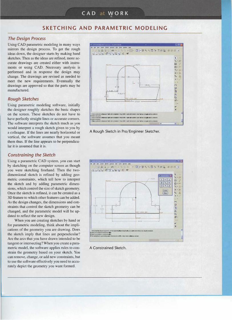
Rough Sketches Using parametric modeling so ftware, init ially the design er roughly sketches the basic shapes on the sc ree n. These sketches do not ha ve to have perfectly straight lines or accurate corners. The software interprets the ske tch much as you would interpret a rou gh sketch g iven to you by a co lleague. if the lines are nearly hori zontal or verti cal , the so ftware assumes that you meant them thus. If the line appears to be perpendicular it is assumed that it is.
Constraining the Sketch Using a parametric CAD sys tem, you can start by sketching on the computer screen as though you wer e sketching freehand . Then the twodimension al sketch is ref ined by adding geo metric constraints, which tell how to interpret the sket ch and by adding parametri c dim ensions, wh ich control the size of ske tch geometry. Once the sketch is refined , it can be creat ed as a 3D feature to which other features can be added . As the desi gn changes, the dim en sion s and constraints that contro l the sketch geometry can be changed, and the parametri c model will be updat ed to refle ct the new design .
When you are creating ske tches by hand or for par ametri c modeling, think about the implications of tbe geo metry you are drawing. Does the sketch imply that lines are perpendicular? Are the arcs that you have drawn intended to be tang ent or inter sectiug ? Wh en you crea te a parametri c model , the so ftware applies rules to constrain the geome try based on your sketch. You can remove, change , or add new constrai nts, but to use the soft ware effective ly you need to accurately depi ct the geometry you want formed.
• \llVl"VRlltRArKl r IAW~) f'" ,IItK. ltllI R - r;1o ~tdil:~"-t~~ltJo !QOII.~t!'b
~ q <') c- , .u · C1 ~ 'i!i -, '" '. 1~ fj I'i, L§l ~
lZLJ~~ It'. e~':lr.. ~ ~ ~7
" ~
D o ;' 0 ' '''
~R.QNI C=::::
..... :.' . L . ~.
v .~/"I ""
L
• ....,.,~ar( IlI "'~J " qi:Lt-:'k" IO~1 ".~t9.1"":J'~d<:ttQ lI;o:ltOMol tb"'ytQlowlr.K( .,·.c<;r4l'r_ . • S-.d«lrtflQl"lf · """"" CCtlW_ ,,~ fqifttk~lo do:l.3blot l:" PrvuWt+ ' '(j'i.dR toft:t. t '-"-labb7Ibl~ '-:b\1~_ .
iiOos.lt<l:.,.0400nt . · """-'~"" "'~; 'P'(f'f. dd to """ . """M + nQ'll dcl to b:a. t . UM J tb ... ~tolo9\'lflrectJ,oor~t .... ..
A Rough Sketch in Prof Engineer Sketcher.
x
~
'· D o ;' o v-.... - :. ' L • ;X.
~ - .l.
9' '. 00
~ :.. II:lI 1/
(!*i CEJ
l r ~ 1 cs-« OH.. " 'I
r-. t"~~~~'dolooll.'tl:"""1jIo\)
&J 4 <') ,... • C1 r 'E<"', e. lZl /~ I:~W,: .~ ':lb. . ~. £ ~7
~ 1 _ lnorl f~~I). lIf t ...o .cjI: ' i. "J "-" . '.. :uoI, ..:lo:t.<I'.'I.*... .. od ' '''''l' or'' ' (It'lJ.''' ~IJI' ..atUl') oO-S*:ttwO _ ... or"""'l<.. to IIIIl;Jl .~hooo",,","lIf¥Wtloos t Qo ."" .rr.~'«Jt'Jltr..ci I) andZ~tl ~s.ct 1T'oll t o ~lIl llt ( ~t .
A Constrained Sketch.

82 CHAPTER 3 TECHNICAL SKETCHING
SKETCHING IN THE FIELD
t I .~I LL P4A
"'....... I:c....-f)..,. t-I\:~ ~ ld·I,.:l~"'f
~,
. \ _ .l •
Andrea Orr is a student in environment design at Montana State University and a co-fundraiser and co-project designer in the MSU chapter of Engineers without Borders.
She created the sketch above during the building of a composting latrine that she and Chris Allen designed for a school in the Khwisero Division of southweste rn Kenya. The sketch showed instructors and local government official how the latrine would work.
Through they had done multiple sketches ahead of time, she and Allen did this complied sketch to clarify their idea s into one concept.
Orr did the sketch outdoors, sitting next to the school building. There was no computer available, because at the remote location, electricity was rarely available. She also did a drawing explaining how to use and maintain the latrine, which was posted inside the finished struc ture.
Sketch for a Composting Latrine . The student chapter of Engineers Without Borders at Montana State University is collaborating with 57 schools in the Khwisero Division of southwestern Kenya to provide sustainable sanitary improvements including wells and compostinq latrines. Sketch courtesy of Andrea Orr, Engineers Without Borders, MSU.
Orr said that when she is not working in the field, she still sketches hy hand hefore transferring to CAD.
"There' s little hit of vagueness in a hand drawn sketch that keeps it open to creativity," said Orr.
" If you show a sketch to someone they are more likely to offer input and ideas than if it looks like a fini shed CAD rendering. That's one of the reasons I don 't work in CAD until quite a few versions into the project."

83 P0 RTF 0 L I 0
"'0
o ::c
A Sketch for the ENV BIke. Courtesyof Seymourpowell. -I 'Tl
o r-
Tor 0:: ocn A ..,I N C .....
e-"" '<
.. N /I (hf ru;,A re bA~ o..., p. l l"r,~. " f'~ .. ce .... .J'" f!.oA {J WI* "( :~oti.T C ,.._I .... N O t1 .$ 1O~ ~ e- o t'e.,5 6 ~A Cr: OF C t' I' '' ' ' L.
,.., JO ~ ' J ,. u tl _ t,... e<J "fTO'~
~n olV\
" ~~~ 5" I .J(.. ..." rrul c.rl c-vr .::<.0('''5
~ --...:..... R~I'- 1 1 ~ "" " , JO :;n ,-, c.. ,u G. ~ "J, 1 ' 1
~ .~
rr6!~ [M]®W®iP ' • / PINE TREE CANYON WIND PARK u~ CIVIl EA-'gineering, Inc , MINOR AT·GRADE CROSSING
"
Sketch showing roadway fill details. Courtesy of Meyer Civil Engineering, Inc.

84 CH APTER 3 T EC H N IC A L SK ETC H I NG
KEY WORDS So lids
Surfaces
Planar
Single-Curved
Do uble-C urved
Warped
Po lyhedra
Regular Polyhed ron
Prism
Pyramid
Cy linde r
Co ne
Sp here
Torus
Ellipsoid
Co nstructio n Lin es
Co ntours
Negative Space
Viewpoin t
Shading
Hatching
Edge
Vertex
Point
Lin e
Angle
Freehand Sketch
Line Patt ern s
Proporti on
Pic tor ial Ske tch
O blique Drawi ng
Cavalier Project ion
Ca binet Project ions
Perspecti ve
Vanishing Poin t
CHAPTER SUMMARY • Sketching is a qu ick way of visual izin g and so lving a
drawing problem. It is an effec tive way of communicating with all members of the design tea m.
• There are speci al techn iques for sketching lines, circles, and arcs . These techn iques should be practiced so they become second nature.
• Us ing a gr id makes sketching in prop orti on an easy task . • You ca n ske tch circles by co nstruc ting a square and locat
ing the four tange nt points where the c ircle touches the square .
• A sketched line does not need to look like a CA D or mechanical line . Th e main distin ct ion betw een CA D and instrumen tal dr awing and free hand sketching is the cha racter or technique of the line wo rk .
• Freehand sketches are mad e to proporti on , but not necessa rily to a part icular sca le.
• Sketc hing is one of the most imp or tant ski lls for accurately recording ideas.
• Mov ing yo ur thumb up or down the len gth of a pencil at arms leng th is an eas y meth od for es tima ting prop ortio na l size .
REVIEW QUESTIONS 1. What are the adv antages of using grid pape r for ske tching'! 2. Wh at is the correc t techn ique for sketching a ci rcle or arc? 3. Ske tch the alph abet of lines. Whi cb lines are thick ? Whi ch
are thin '! Wh ich are very light and wi ll not rep roduce when co pie d?
4. Wh at type of 3D dra wing ca n eas ily be drawn on square grid paper ?
5. Wh at is the advantage of sketching an object first before drawin g it using CA D?
6. Wh at is the difference be twee n proportion and scale?

85 5 K ET C H I N G E X ERe I 5 E 5
SKETCHING EXERCISES
Exercise 3 .1 Quick Sketch . © 2007 Jupiterimages Corporation. 1. Practice the sketching skills and techn iques you have learned for construction
lines and ellipses . Set a timer for 10 minutes and make quick sketches of these nine different cups.
2. Select one cup and crea te iso metric. oblique. and perspective drawings . 3. Design a new piece of drinkware, using your sketching skills. 4. Select one cup. Draw an enclos ing box and shade in the negative space so that
the contour of the cup remains white.
(b) (c)(a)
(d) (e) (I)
(h) (i)(g)

86 CHAPTER 3 TECHNI CA L S K ETC H I NG
Exercise 3.2 Quick Sketch . © 2007 Jupit erimages Corporation. See instructions for Exercise 3. 1. part I .
(a) (b)
(e) (d)
( (e) (f)

87 5 K ETC H I N G EX ERe I 5 E5
Exercise 3.3 Quick Sketch. © Jupiterima ges Corporation. See instructions for Exercise 3.1. part I .
(a) (b)
(c) (d)
(e) (f)

88 CHAPTER 3 TECHNICAL SKETCHING
Exercise 3 .4 Sketching. © Jupiterimages Corporation. See instructions for Exercise 3.1 , part I.
(c)
(a)
(b)
(d) (e)

3
o 0> M
SKET CHIN G EXER CI SE S
~.50 -
I " I ;
- - - - - - - - - ---- - - - ---.l rl= --- ~ ffi
..L:F ~---+ 2 X 2.500 .625 -
8 equal spaces
8 equal spaces
(Use bow d/v/d7:rs)
2X 1. 250
"r <t
'" 1.25 -1f-- - - 5. 000 SO - - -. ~ I. ~ O ~ 1.000 ~
PLAS TICS MOLD ER PLATE VAXY . TO M Q .
(Use bow d ividers)
tf-~· ------, I
Exercise 3.7 Draw views in pencil, as show n. Omit a ll dimen sions.
Exercise 3 .5 Divide working space into six equal rectangles and draw visible lines. as shown. Draw co nstruction lines AB through centers C at right angles to requi red lines; then along each construction line, set off 0.50" spaces and draw required visible lines. Omit dimensions and instructional notes.
Exercise 3 .6 Divide working space into six equal rectangles and draw lines as shown . In the first two spaces. draw conve ntional lines to match those in Figure 3.23 . In remainin g spaces, locate centers C by diagonals. and then work construc tions out from them . Om it the metric dimensions and instructional notes.

90 CHAPTER 3 TECHNICAL SKETCHING
Exercise 3 .8 Draw the figures in pencil, as shown. Omit all dimen sions .
70- - --1- - - - - / 2 5 - - - - --I
IMETRIC I ARCS AN D CI RCLES VAXY , TOM Q ,
Exercise 3.9 Draw the views in pencil , 1 1~4 o o --t------as shown. Omit all dimensions.
2X ¢.312
i1'o ~ r')
12X ¢ 2.005
;A
{ -r-...-- +-->---\-----PI-{-' 'l -/-.L..L+-+----+-------,4
.
I 01 L PUMP BODY VAX Y. T OM Q .
4X 30 °
Exercise 3.10 Draw the friction plate using pencil. Omit dimensions and notes.
¢ 154
IMETRI C I
4
98

5 K ETC H I N G EX ERe I 5 E5 91
I' I I I 1 I I IbL __ -.J
38----1
IMETRIC I
Exercise 3. 11 Draw views of the seal cover using pencil. Omit the dimensions and notes.
0 25 40 .6.50 X3 .25 KWY 25.35
IMETRIC I
Exercise 3 .12 Draw the Geneva cam using pencil. Omit dimen sions and notes.
0 19 .0 5 19 .0 0
(3127
¢1 52
HUB-¢38
Exercise 3. 14 Draw the ratchet wheel using pencil. Omit the dimensions and notes.
2X R
AB= 94 FG = 61 F IMETRIC I
BC = 40 GH= 4 8
CD= 35 HJ = 8 5
DE = 57 -..JK -=53
EF -= 87 KA =
J
Exercise3. 13 Draw accurately in pencil the shear plate. Give the length of KA. Omit the other dimensions and notes.
4X 0.50
Exercise 3. 15 Draw the latch plate using pencil. Omit the dimensions and notes.