Chapter 6f
42
VIRTUAL WORK & RECIPROCAL PRINCIPLES CHAPTER 6
description
fghfghf
Transcript of Chapter 6f

7/17/2019 Chapter 6f
http://slidepdf.com/reader/full/chapter-6f 1/42
VIRTUAL WORK
& RECIPROCAL PRINCIPLESCHAPTER 6
7/17/2019 Chapter 6f
http://slidepdf.com/reader/full/chapter-6f 2/42
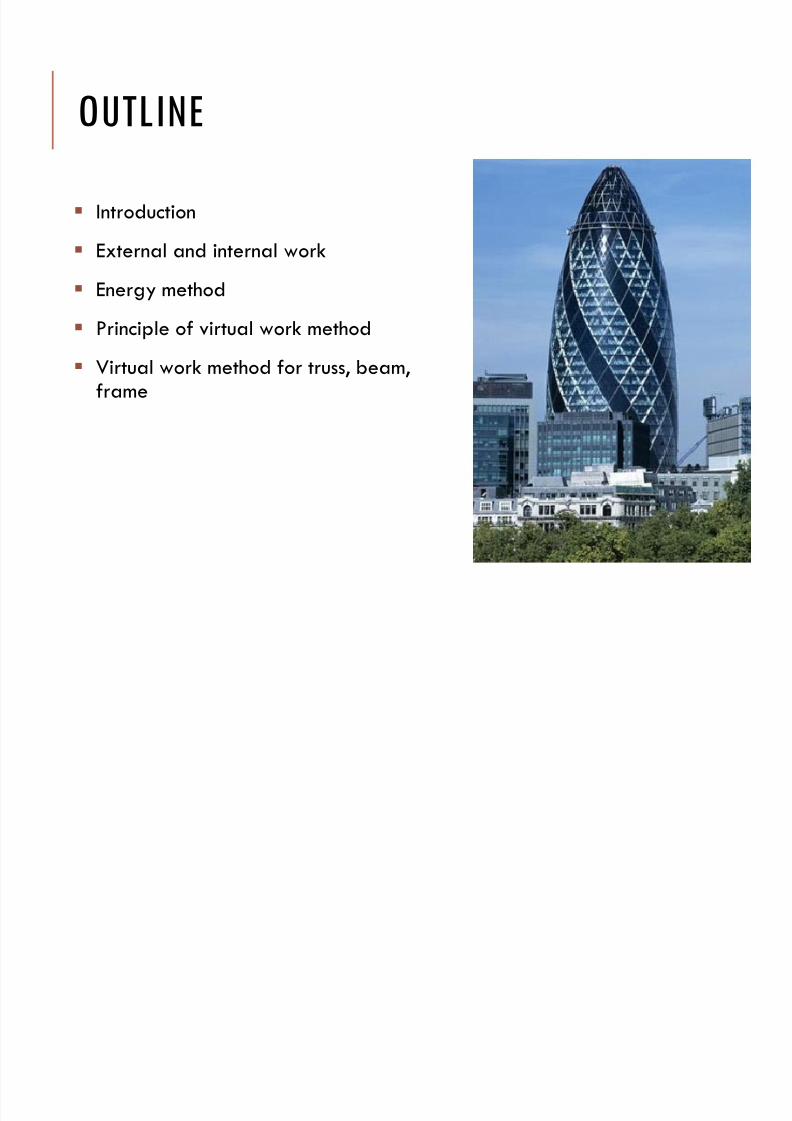
OUTLINE
Introduction
External and internal work
Energy method
Principle of virtual work method
Virtual work method for truss, beam,frame
7/17/2019 Chapter 6f
http://slidepdf.com/reader/full/chapter-6f 3/42
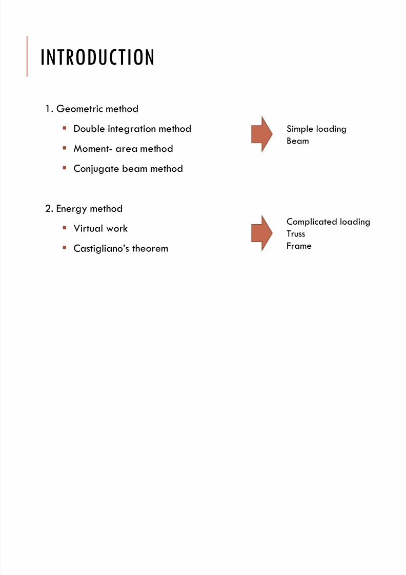
INTRODUCTION
1. Geometric method
Double integration method
Moment- area method
Conjugate beam method
2. Energy method Virtual work
Castigliano’s theorem
Simple loading
Beam
Complicated loading
Truss
Frame
7/17/2019 Chapter 6f
http://slidepdf.com/reader/full/chapter-6f 4/42
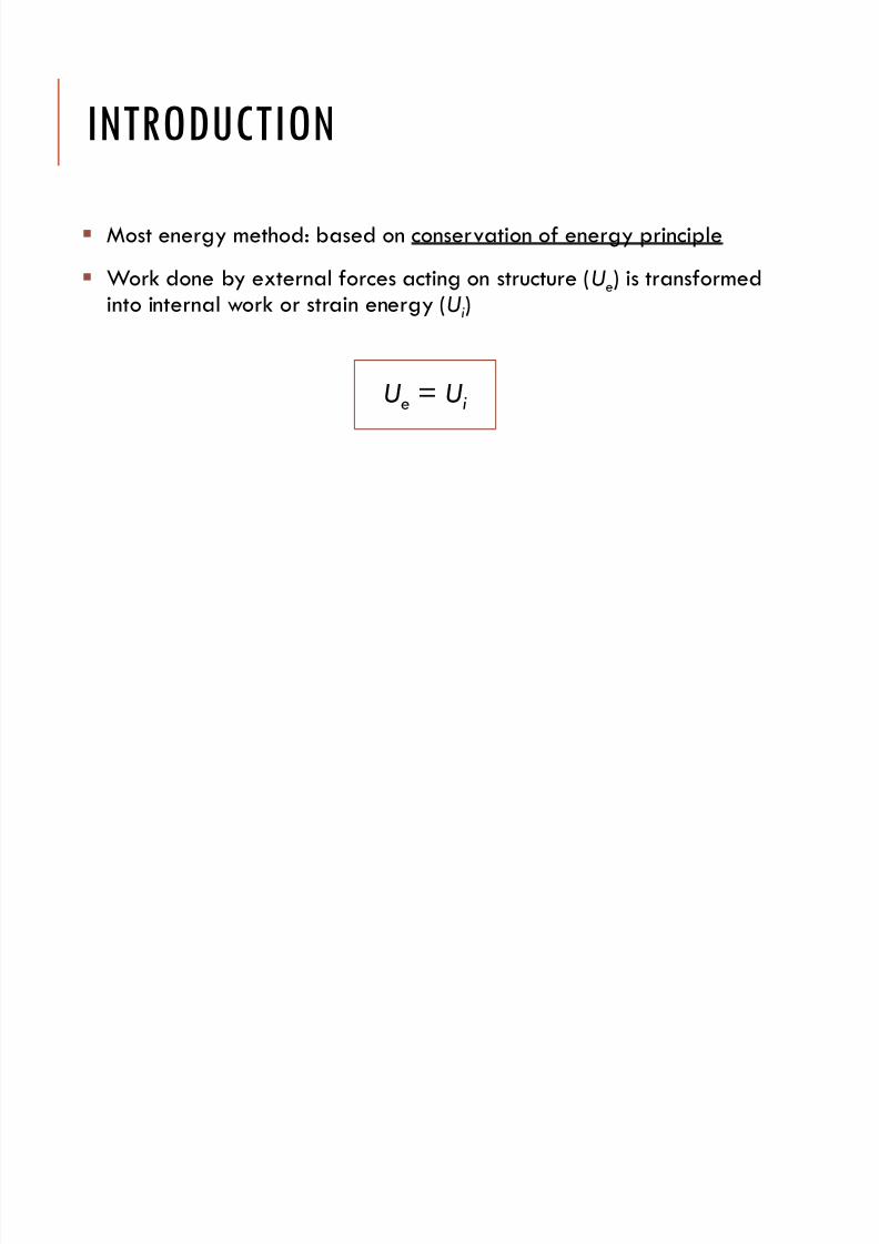
INTRODUCTION
Most energy method: based on conservation of energy principle
Work done by external forces acting on structure (Ue) is transformed
into internal work or strain energy (Ui)
Ue
= Ui
7/17/2019 Chapter 6f
http://slidepdf.com/reader/full/chapter-6f 5/42
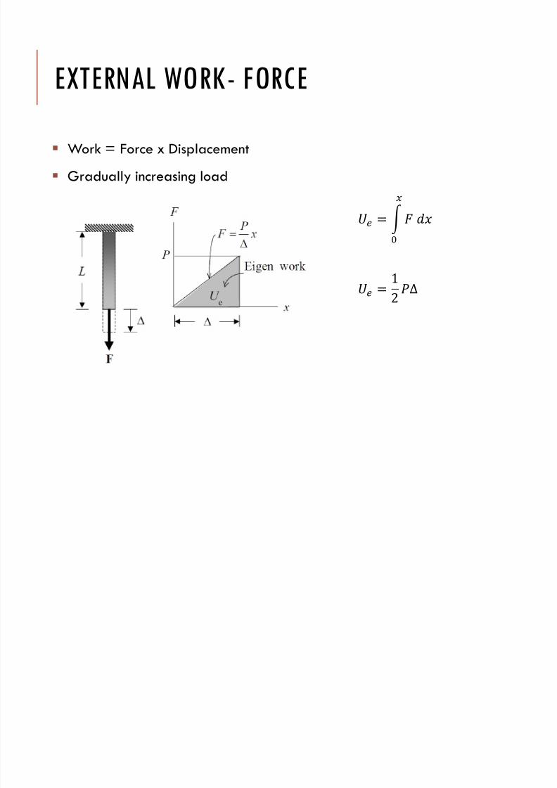
EXTERNAL WORK- FORCE
Work = Force x Displacement
Gradually increasing load
=
= 12∆
7/17/2019 Chapter 6f
http://slidepdf.com/reader/full/chapter-6f 6/42
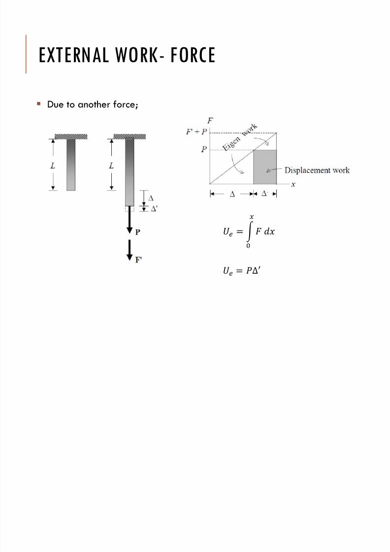
EXTERNAL WORK- FORCE
Due to another force;
=
= ∆′
7/17/2019 Chapter 6f
http://slidepdf.com/reader/full/chapter-6f 7/42
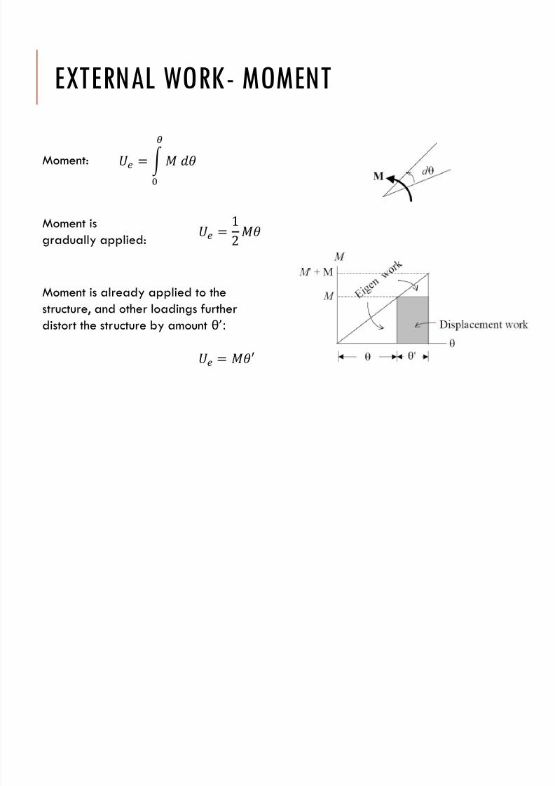
EXTERNAL WORK- MOMENT
=
= 12
= ′
Moment:
Moment is
gradually applied:
Moment is already applied to thestructure, and other loadings further
distort the structure by amount θ’:
7/17/2019 Chapter 6f
http://slidepdf.com/reader/full/chapter-6f 8/42
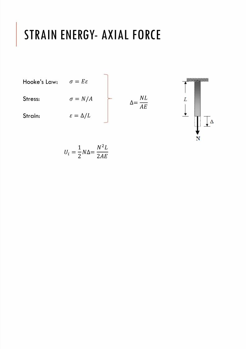
STRAIN ENERGY- AXIAL FORCE
Hooke’s Law:
Stress:
Strain:
= = /
= ∆/∆=
= 12∆=
2
7/17/2019 Chapter 6f
http://slidepdf.com/reader/full/chapter-6f 9/42
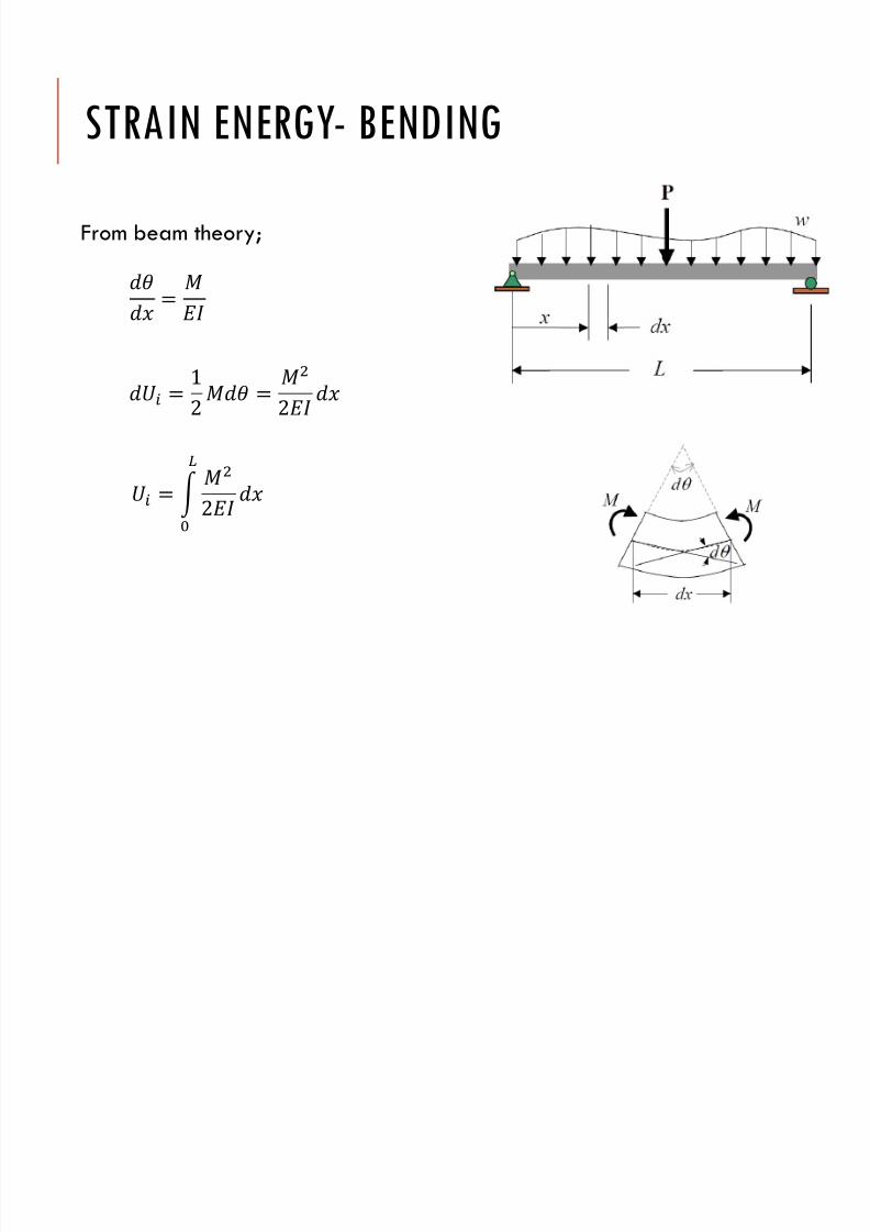
STRAIN ENERGY- BENDING
From beam theory;
=
= 12 =
2
=
2
7/17/2019 Chapter 6f
http://slidepdf.com/reader/full/chapter-6f 10/42
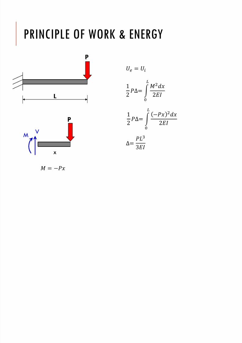
PRINCIPLE OF WORK & ENERGY
P
L
x
VM
P
=
12∆= 2
1
2∆=
2∆=
3
=
7/17/2019 Chapter 6f
http://slidepdf.com/reader/full/chapter-6f 11/42
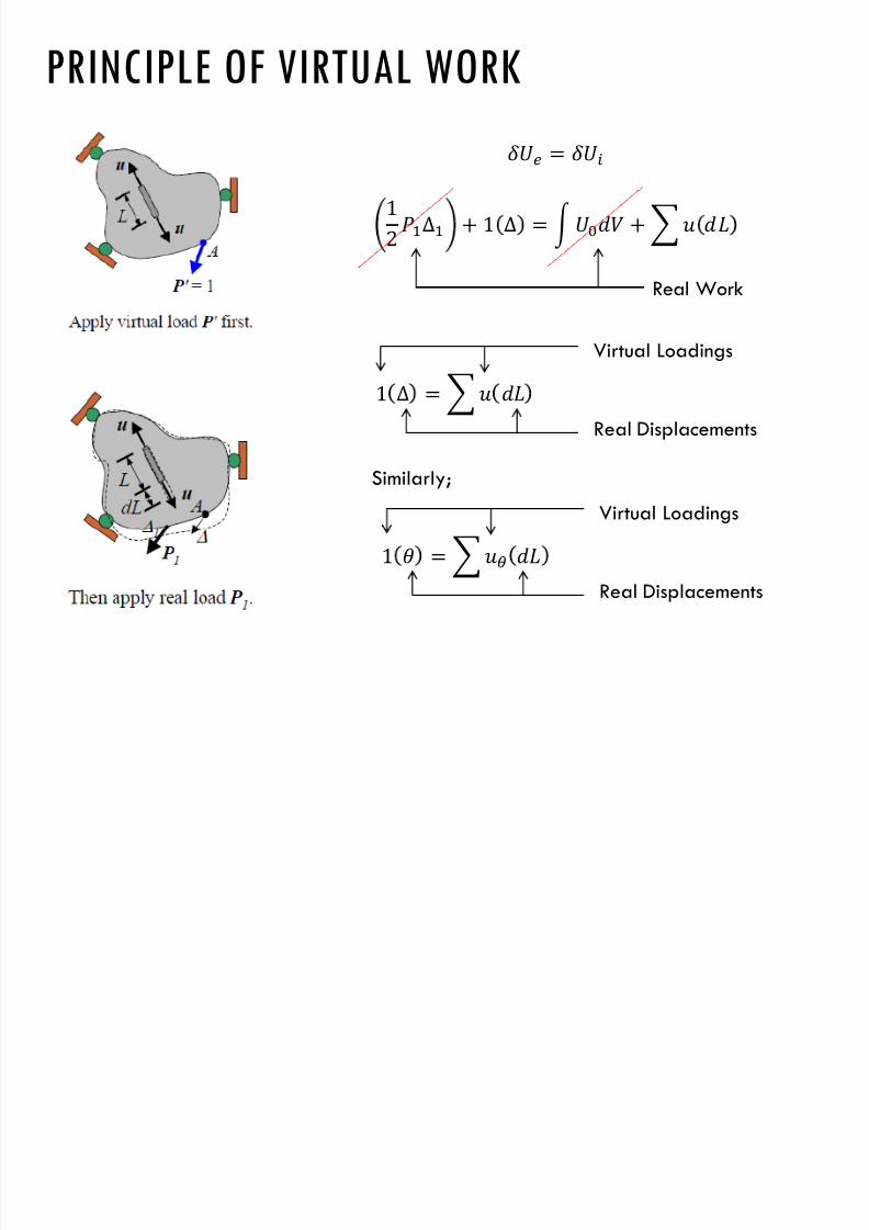
PRINCIPLE OF VIRTUAL WORK
Provide generalization of equilibrium and compatibility concepts
Apply to linear and non-linear structures and solids under small and
large displacements
Unit load method (or dummy load method) is derived from principleof virtual work – powerful tool to evaluate displacements
7/17/2019 Chapter 6f
http://slidepdf.com/reader/full/chapter-6f 12/42
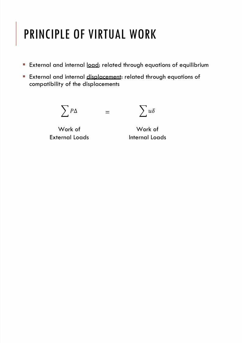
PRINCIPLE OF VIRTUAL WORK
External and internal load: related through equations of equilibrium
External and internal displacement: related through equations of
compatibility of the displacements
∆
Work ofExternal Loads
Work ofInternal Loads
=
7/17/2019 Chapter 6f
http://slidepdf.com/reader/full/chapter-6f 13/42
PRINCIPLE OF VIRTUAL WORK
= 12∆ + 1 ∆ = +
Real Work
1 ∆ = Virtual Loadings
Real Displacements
Similarly;
1 = Virtual Loadings
Real Displacements
7/17/2019 Chapter 6f
http://slidepdf.com/reader/full/chapter-6f 14/42
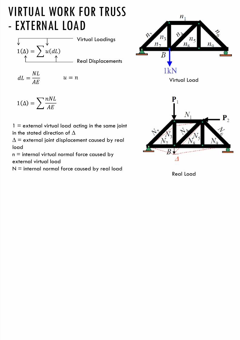
VIRTUAL WORK FOR TRUSS
- EXTERNAL LOAD
Virtual Load
Real Load
1 ∆ = Virtual Loadings
Real Displacements
=
=
1 ∆ =
1 = external virtual load acting in the same jointin the stated direction of ∆
∆ = external joint displacement caused by real
load
n = internal virtual normal force caused by
external virtual load
N = internal normal force caused by real load
7/17/2019 Chapter 6f
http://slidepdf.com/reader/full/chapter-6f 15/42
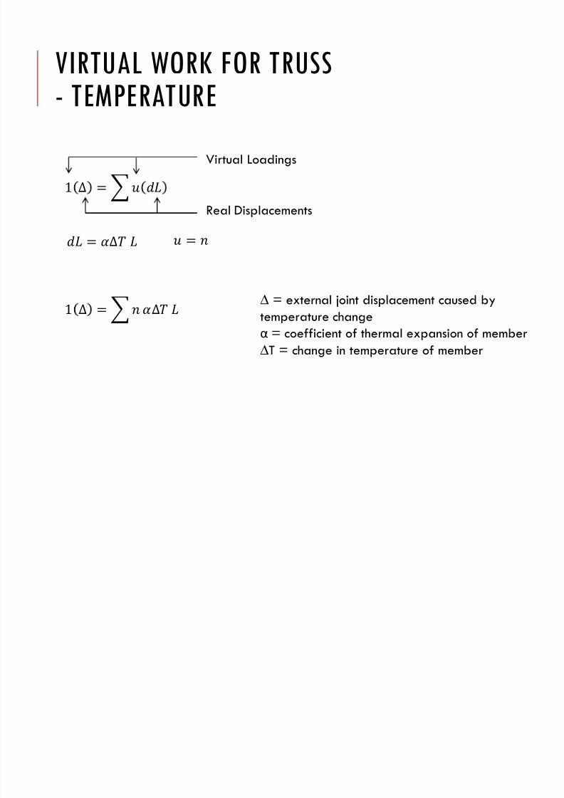
VIRTUAL WORK FOR TRUSS
- TEMPERATURE
1 ∆ =
Virtual Loadings
Real Displacements
= ∆ =
1 ∆ = ∆ ∆ = external joint displacement caused bytemperature change
α = coefficient of thermal expansion of member
∆T = change in temperature of member

7/17/2019 Chapter 6f
http://slidepdf.com/reader/full/chapter-6f 16/42
VIRTUAL WORK FOR TRUSS
- FABRICATION ERROR
1 ∆ =
Virtual Loadings
Real Displacements
= ∆ =
1 ∆ = ∆ ∆ = external joint displacement caused byfabrication error
∆L = difference in length of the member from its
intended size as caused by fabrication error
7/17/2019 Chapter 6f
http://slidepdf.com/reader/full/chapter-6f 17/42
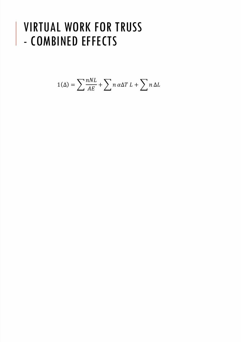
VIRTUAL WORK FOR TRUSS
- COMBINED EFFECTS
1 ∆ = +∆ + ∆
7/17/2019 Chapter 6f
http://slidepdf.com/reader/full/chapter-6f 18/42
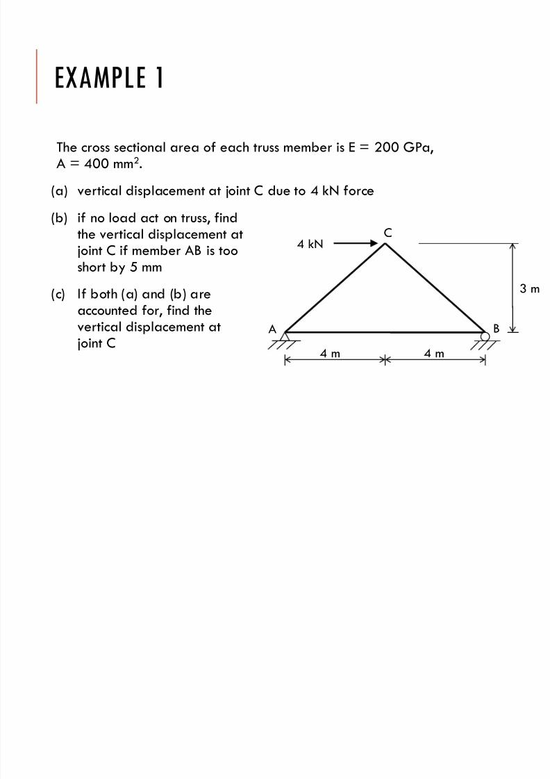
EXAMPLE 1
The cross sectional area of each truss member is E = 200 GPa,A = 400 mm2.
(a) vertical displacement at joint C due to 4 kN force(b) if no load act on truss, find
the vertical displacement atjoint C if member AB is tooshort by 5 mm
(c) If both (a) and (b) areaccounted for, find thevertical displacement atjoint C
A B
C4 kN
4 m 4 m
3 m
7/17/2019 Chapter 6f
http://slidepdf.com/reader/full/chapter-6f 19/42
A B
C
1 kN
3 m
0.5 kN 0.5 kN
0.667
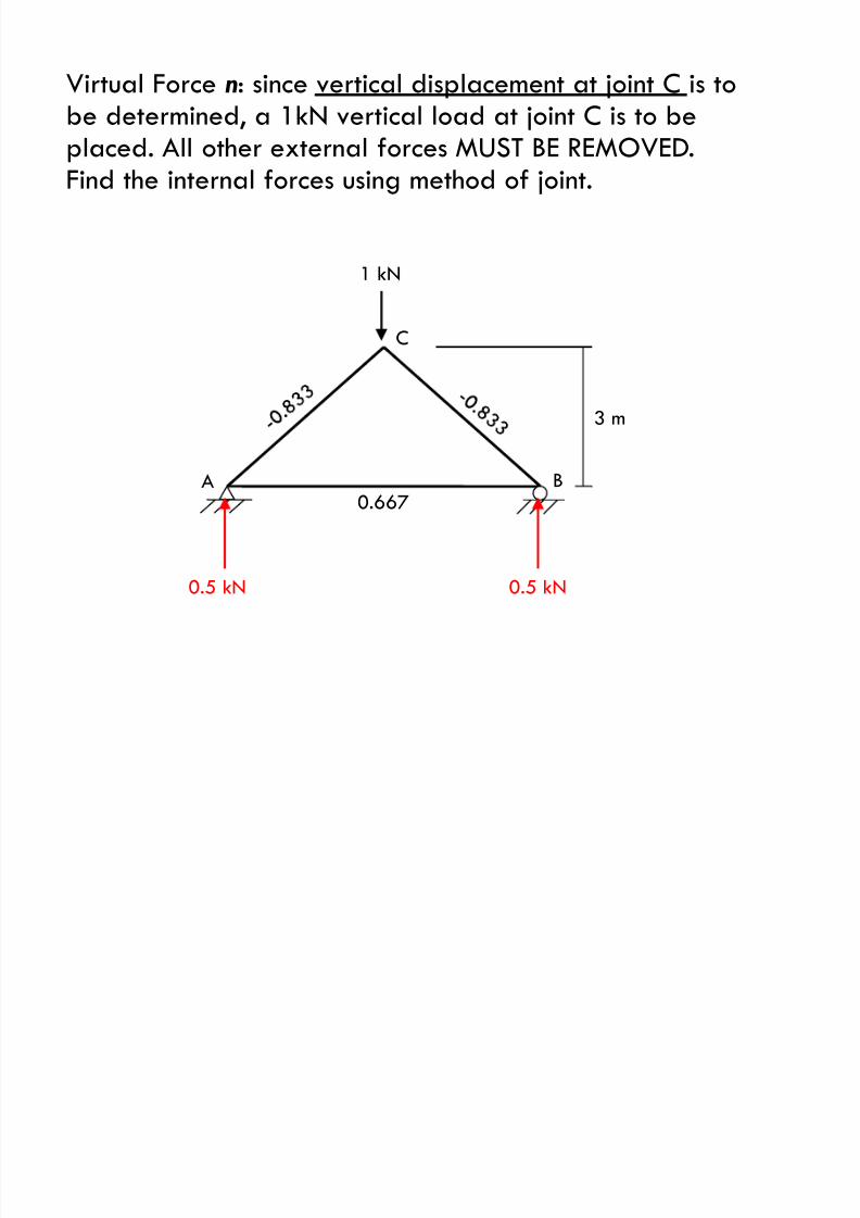
Virtual Force n: since vertical displacement at joint C is tobe determined, a 1kN vertical load at joint C is to be
placed. All other external forces MUST BE REMOVED.Find the internal forces using method of joint.
7/17/2019 Chapter 6f
http://slidepdf.com/reader/full/chapter-6f 20/42
AB
C4 kN
3 m
1.5 kN 1.5 kN
2
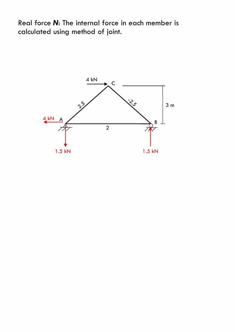
4 kN
Real force N : The internal force in each member iscalculated using method of joint.
7/17/2019 Chapter 6f
http://slidepdf.com/reader/full/chapter-6f 21/42
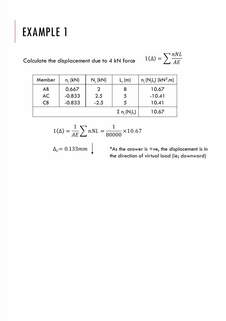
Calculate the displacement due to 4 kN force
Member ni (kN) Ni (kN) Li (m) ni (NiLi) (kN2.m)
AB
AC
CB
0.667
-0.833
-0.833
2
2.5
-2.5
8
5
5
10.67
-10.41
10.41
Σ ni (NiLi) 10.67
EXAMPLE 1
1 ∆ =
1 ∆ = 1 = 1
80000 ×10.67
∆= 0.133 *As the answer is +ve, the displacement is in
the direction of virtual load (ie; downward)
7/17/2019 Chapter 6f
http://slidepdf.com/reader/full/chapter-6f 22/42
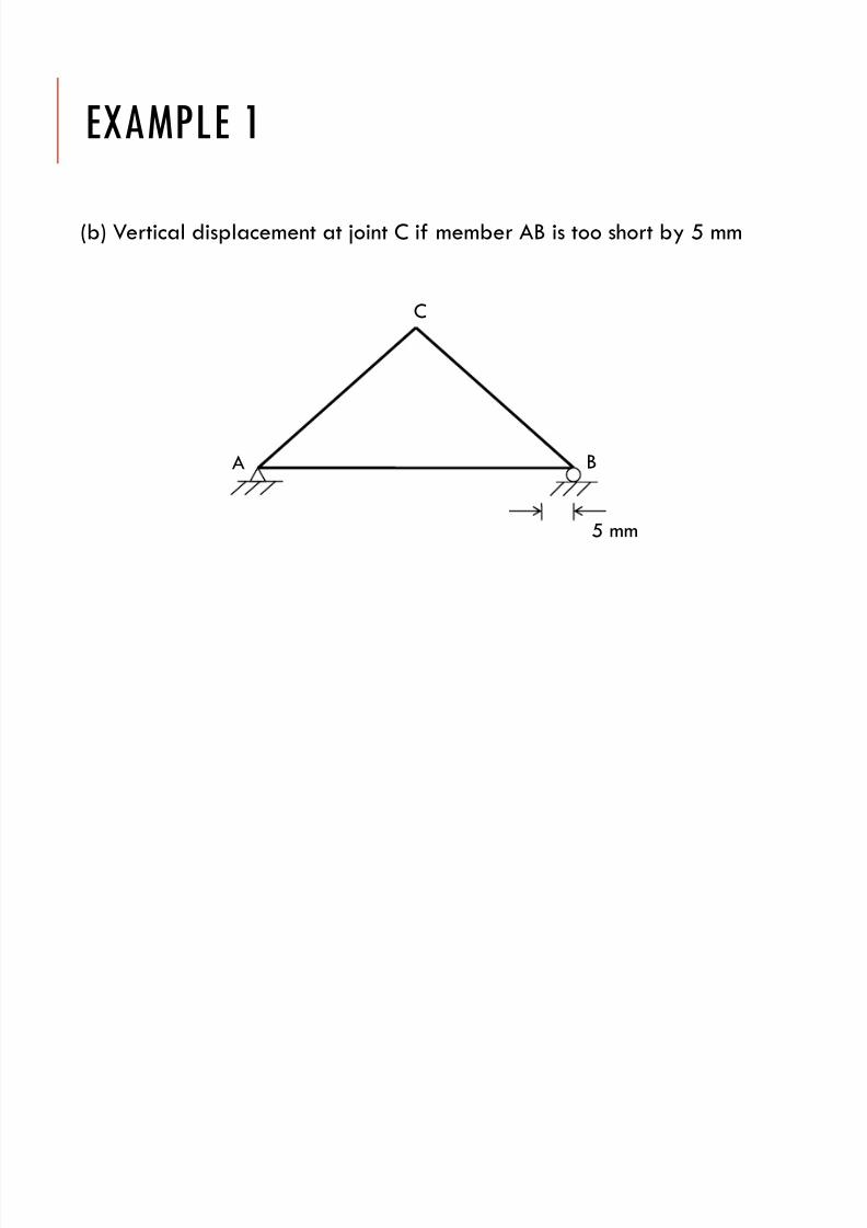
EXAMPLE 1
(b) Vertical displacement at joint C if member AB is too short by 5 mm
A B
C
5 mm
7/17/2019 Chapter 6f
http://slidepdf.com/reader/full/chapter-6f 23/42
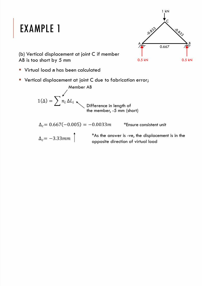
EXAMPLE 1
(b) Vertical displacement at joint C if memberAB is too short by 5 mm
Virtual load n has been calculated Vertical displacement at joint C due to fabrication error;
1 ∆ = ∆
Member AB
Difference in length ofthe member, -5 mm (short)
∆= 0.667 0.005 = 0.0033
∆= 3.33
*Ensure consistent unit
*As the answer is -ve, the displacement is in the
opposite direction of virtual load
A B
C
1 kN
0.5 kN 0.5 kN
0.667
7/17/2019 Chapter 6f
http://slidepdf.com/reader/full/chapter-6f 24/42
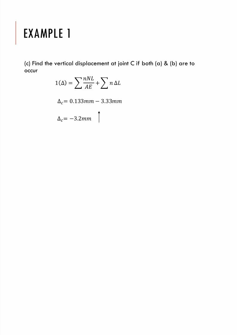
EXAMPLE 1
(c) Find the vertical displacement at joint C if both (a) & (b) are tooccur
1 ∆ = +∆∆= 0.133 3.33
∆= 3.2
7/17/2019 Chapter 6f
http://slidepdf.com/reader/full/chapter-6f 25/42
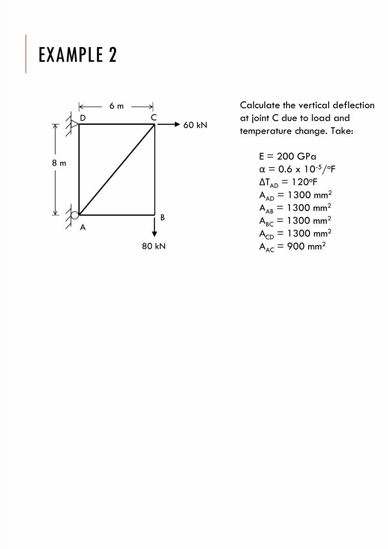
EXAMPLE 2
Calculate the vertical deflection
at joint C due to load and
temperature change. Take:
E = 200 GPa
α = 0.6 x 10⁻⁵/oF
ΔTAD = 120oF
AAD = 1300 mm2
AAB = 1300 mm2
ABC = 1300 mm2
ACD = 1300 mm2
AAC = 900 mm2
60 kN
80 kN
8 m
AB
CD
6 m
7/17/2019 Chapter 6f
http://slidepdf.com/reader/full/chapter-6f 26/42
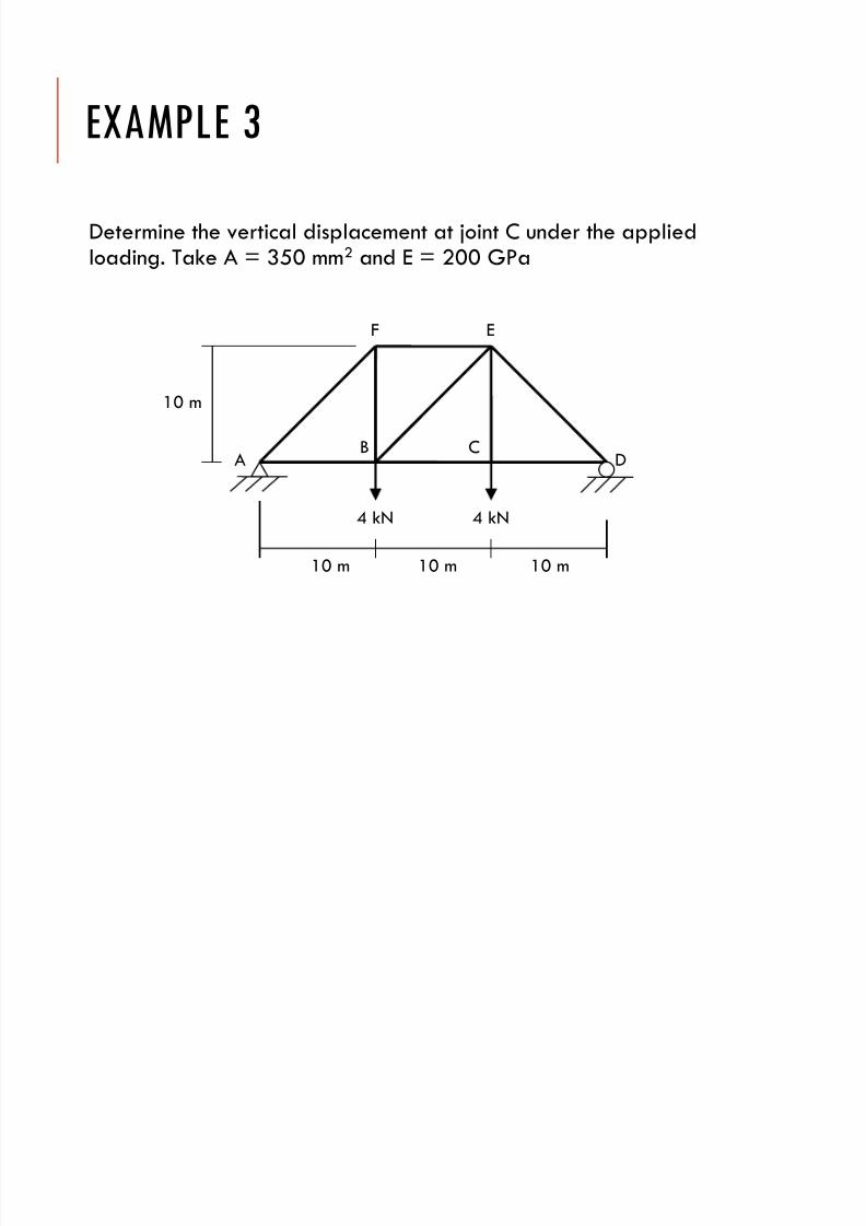
EXAMPLE 3
Determine the vertical displacement at joint C under the appliedloading. Take A = 350 mm2 and E = 200 GPa
4 kN
A
4 kN
B CD
EF
10 m
10 m 10 m 10 m
7/17/2019 Chapter 6f
http://slidepdf.com/reader/full/chapter-6f 27/42
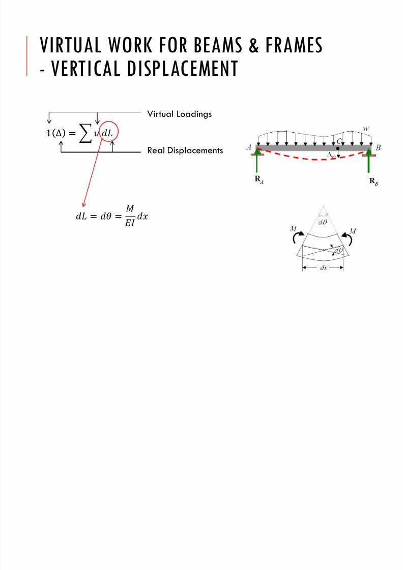
VIRTUAL WORK FOR BEAMS & FRAMES
- VERTICAL DISPLACEMENT
1 ∆ =
Virtual Loadings
Real Displacements
= =
7/17/2019 Chapter 6f
http://slidepdf.com/reader/full/chapter-6f 28/42
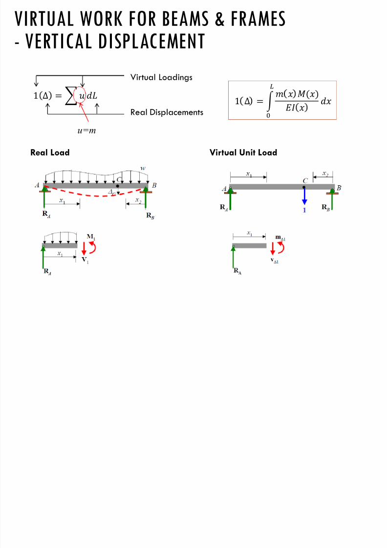
VIRTUAL WORK FOR BEAMS & FRAMES
- VERTICAL DISPLACEMENT
1 ∆ = Virtual Loadings
Real Displacements1 ∆ =
()
Real Load Virtual Unit Load
u=m
7/17/2019 Chapter 6f
http://slidepdf.com/reader/full/chapter-6f 29/42
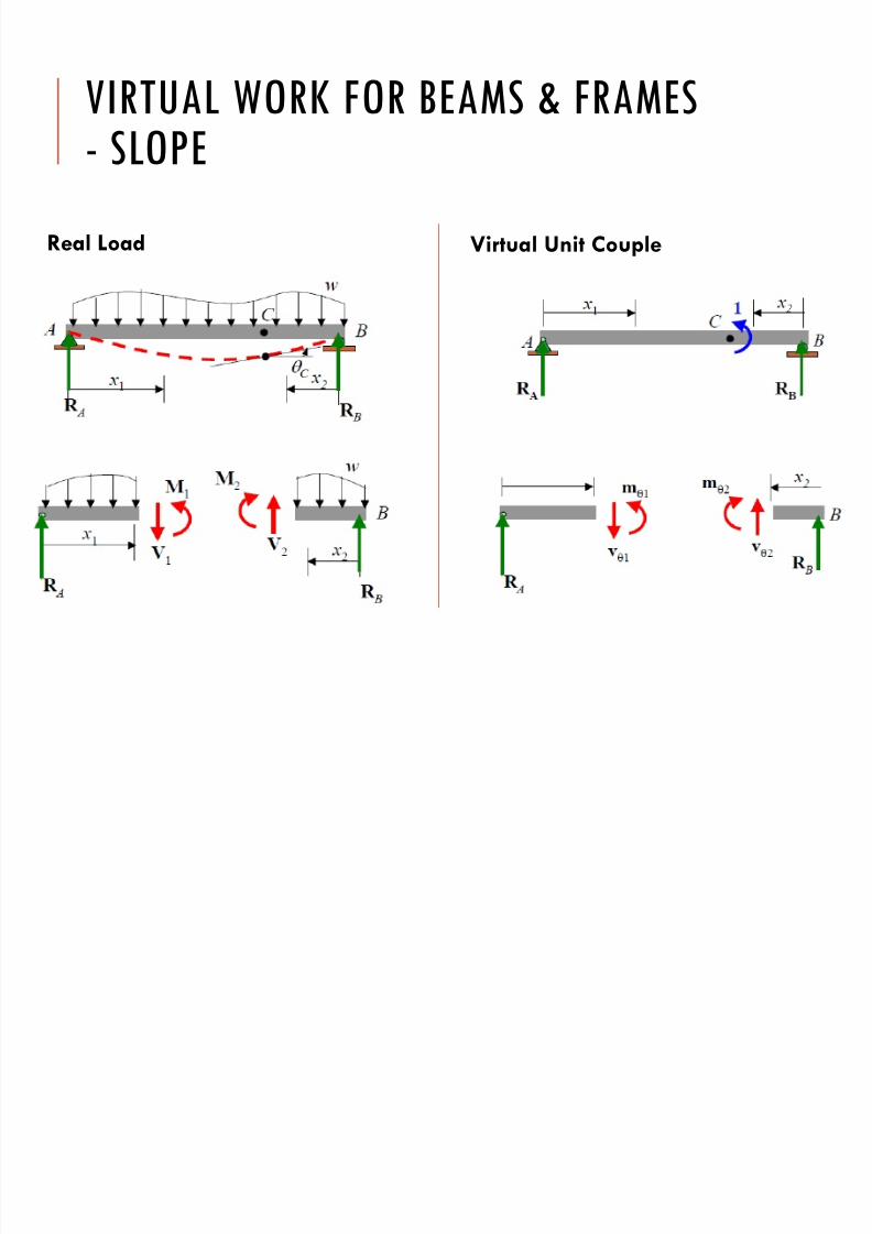
VIRTUAL WORK FOR BEAMS & FRAMES
- SLOPE
Real Load Virtual Unit Couple

7/17/2019 Chapter 6f
http://slidepdf.com/reader/full/chapter-6f 30/42
VIRTUAL WORK FOR BEAMS & FRAMES
- SLOPE
1 =
Virtual Loadings
Real Displacements
1 =
()
= =
=
7/17/2019 Chapter 6f
http://slidepdf.com/reader/full/chapter-6f 31/42
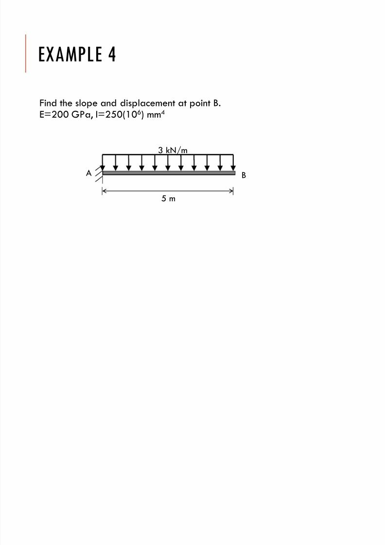
EXAMPLE 4
Find the slope and displacement at point B.E=200 GPa, I=250(106) mm4
3 kN/m
5 m
A B
7/17/2019 Chapter 6f
http://slidepdf.com/reader/full/chapter-6f 32/42
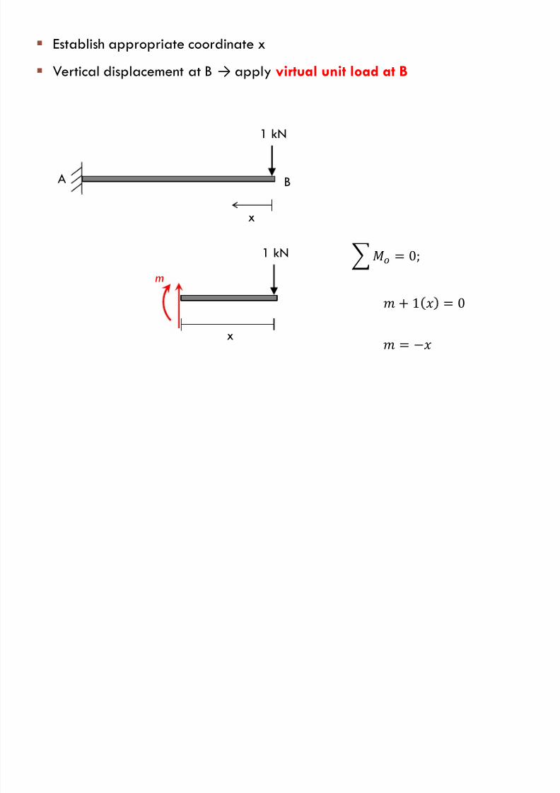
Establish appropriate coordinate x
Vertical displacement at B → apply virtual unit load at B
1 kN
x
A B
1 kN
x
m
= 0;
= + 1 = 0
7/17/2019 Chapter 6f
http://slidepdf.com/reader/full/chapter-6f 33/42
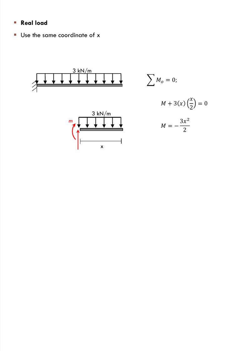
Real load
Use the same coordinate of x
3 kN/m
x
m
= 0;
+ 3 2 = 0
3 kN/m
=
3
2
7/17/2019 Chapter 6f
http://slidepdf.com/reader/full/chapter-6f 34/42
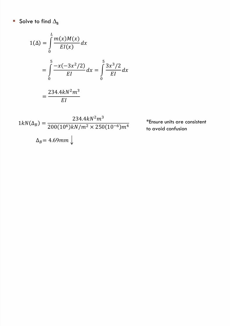
Solve to find ∆B
1 ∆ =
()
=
3/2 =
3/2
= 234.4
1 ∆ = 234.4
200 10 / × 250 10−
∆= 4.69
*Ensure units are consistentto avoid confusion
7/17/2019 Chapter 6f
http://slidepdf.com/reader/full/chapter-6f 35/42
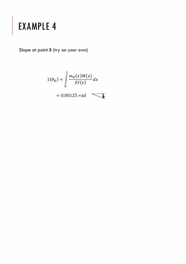
1 =
()
= 0.00125
EXAMPLE 4
Slope at point B (try on your own)
7/17/2019 Chapter 6f
http://slidepdf.com/reader/full/chapter-6f 36/42
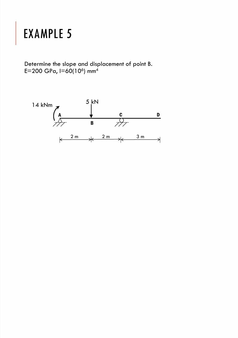
EXAMPLE 5
Determine the slope and displacement of point B.E=200 GPa, I=60(106) mm4
5 kN
A
B
C D
14 kNm
2 m 2 m 3 m
7/17/2019 Chapter 6f
http://slidepdf.com/reader/full/chapter-6f 37/42
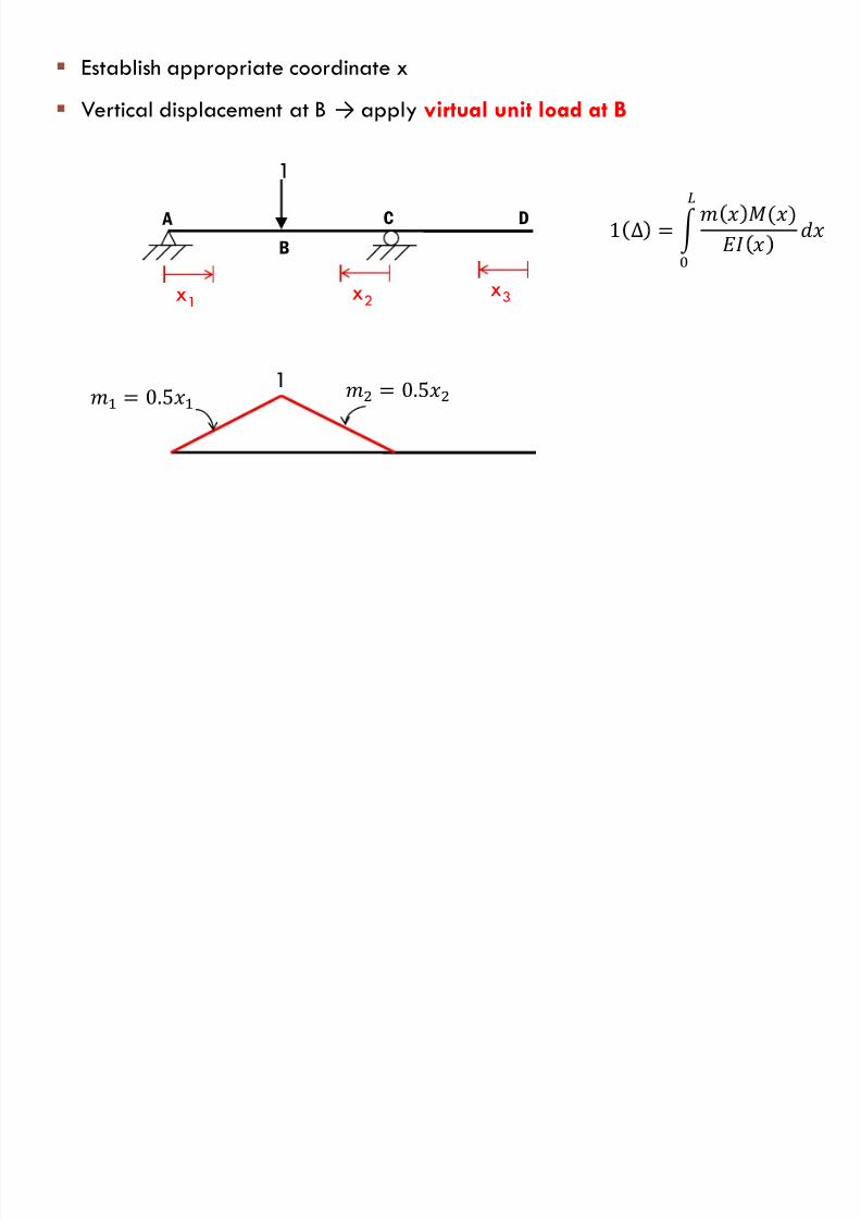
Establish appropriate coordinate x
Vertical displacement at B → apply virtual unit load at B
1
A
B
C D
x1
x2
x3
1 = 0.5 = 0.5
1 ∆ =
()
7/17/2019 Chapter 6f
http://slidepdf.com/reader/full/chapter-6f 38/42
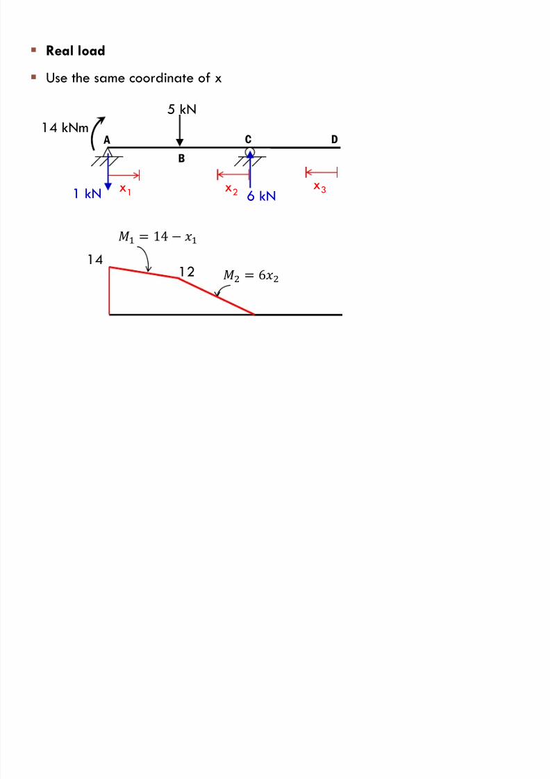
Real load
Use the same coordinate of x
5 kN
A
B
C D
x1
x2
x3
14 kNm
14
= 14
= 6
6 kN1 kN
12
7/17/2019 Chapter 6f
http://slidepdf.com/reader/full/chapter-6f 39/42
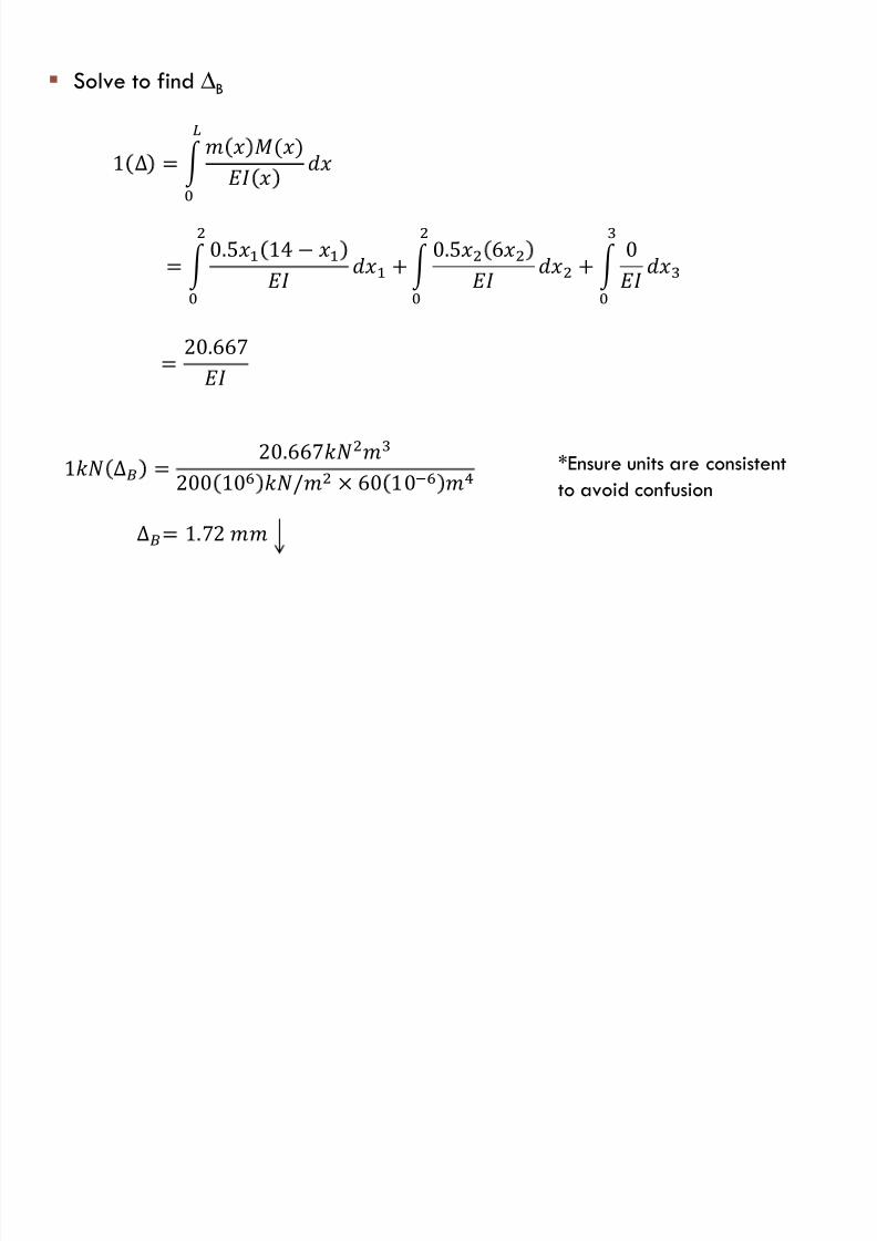
Solve to find ∆B
1 ∆ =
()
=
0.5 14 +
0.5 6 +
0
= 20.667
1 ∆ = 20.667
200 10 / × 60 10−
∆= 1.72
*Ensure units are consistentto avoid confusion

7/17/2019 Chapter 6f
http://slidepdf.com/reader/full/chapter-6f 40/42
Slope at point B (try on your own)
1 =
()
= 0.000194
EXAMPLE 5
7/17/2019 Chapter 6f
http://slidepdf.com/reader/full/chapter-6f 41/42
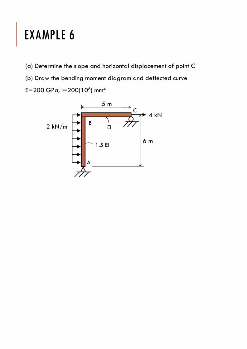
EXAMPLE 6
(a) Determine the slope and horizontal displacement of point C
(b) Draw the bending moment diagram and deflected curve
E=200 GPa, I=200(106) mm4
5 m
A
B
4 kN
6 m
2 kN/m
C
1.5 EI
EI

7/17/2019 Chapter 6f
http://slidepdf.com/reader/full/chapter-6f 42/42
QUESTIONS?