Chapter 5 Seismic Code Developments for Steel and ...
23
Chapter 5 Seismic Code Developments for Steel and Composite Structures Ahmed Y. Elghazouli Abstract As with other codified guidance, seismic design requirements undergo a process of continuous evolution and development. This process is usually guided by improved understanding of structural behaviour based on new research findings, coupled with the need to address issues identified from the practical application of code procedures in real engineering projects. Developments in design guidance however need to balance detailed technical advancements with the desire to main- tain a level of practical stability and simplicity in codified rules. As a result, design procedures inevitably incorporate various simplifications and idealisations which can in some cases have adverse implications on the expected seismic performance and hence on the rationale and reliability of the design approaches. With a view to identifying the needs for future seismic code developments, this paper focuses on assessing the underlying approaches and main procedures adopted in the seismic design of steel and composite framed structures, with emphasis on the current European seismic design code, Eurocode 8. Codified requirements in terms of force reduction factors, ductility considerations, capacity design verifications, and connection design procedures, are examined. Various requirements that differ notably from other international seismic codes, particularly those incorporated in North American provisions, are also pointed out. The paper highlights various issues related to the seismic design of steel and composite frames that can result in uneconomical or impractical solutions, and outlines several specific seismic code development needs. 5.1 Introduction Steel and composite steel/concrete structures may be designed based on EC8 (Eurocode 8 2005) according to either non-dissipative or dissipative behaviour. The former is normally limited to areas of low seismicity or to structures of special A.Y. Elghazouli (*) Department of Civil and Environmental Engineering, Imperial College London, London, UK e-mail: [email protected] © The Author(s) 2015 A. Ansal (ed.), Perspectives on European Earthquake Engineering and Seismology, Geotechnical, Geological and Earthquake Engineering 39, DOI 10.1007/978-3-319-16964-4_5 129
Transcript of Chapter 5 Seismic Code Developments for Steel and ...

Chapter 5
Seismic Code Developments for Steeland Composite Structures
Ahmed Y. Elghazouli
Abstract As with other codified guidance, seismic design requirements undergo a
process of continuous evolution and development. This process is usually guided by
improved understanding of structural behaviour based on new research findings,
coupled with the need to address issues identified from the practical application of
code procedures in real engineering projects. Developments in design guidance
however need to balance detailed technical advancements with the desire to main-
tain a level of practical stability and simplicity in codified rules. As a result, design
procedures inevitably incorporate various simplifications and idealisations which
can in some cases have adverse implications on the expected seismic performance
and hence on the rationale and reliability of the design approaches. With a view to
identifying the needs for future seismic code developments, this paper focuses on
assessing the underlying approaches and main procedures adopted in the seismic
design of steel and composite framed structures, with emphasis on the current
European seismic design code, Eurocode 8. Codified requirements in terms of
force reduction factors, ductility considerations, capacity design verifications, and
connection design procedures, are examined. Various requirements that differ
notably from other international seismic codes, particularly those incorporated in
North American provisions, are also pointed out. The paper highlights various
issues related to the seismic design of steel and composite frames that can result
in uneconomical or impractical solutions, and outlines several specific seismic code
development needs.
5.1 Introduction
Steel and composite steel/concrete structures may be designed based on EC8
(Eurocode 8 2005) according to either non-dissipative or dissipative behaviour.
The former is normally limited to areas of low seismicity or to structures of special
A.Y. Elghazouli (*)
Department of Civil and Environmental Engineering, Imperial College London, London, UK
e-mail: [email protected]
© The Author(s) 2015
A. Ansal (ed.), Perspectives on European Earthquake Engineering and Seismology,Geotechnical, Geological and Earthquake Engineering 39,
DOI 10.1007/978-3-319-16964-4_5
129

use and importance, although it could also be applied for higher seismicity areas if
vibration reduction or isolation devices are incorporated. Otherwise, the code aims
to achieve economical design by employing dissipative behaviour which, apart
from for special irregular or complex structures, is usually performed by assigning a
structural behaviour factor to reduce the code-specified forces resulting from
idealised elastic response spectra. This is carried out in conjunction with the
capacity design concept which requires an appropriate determination of the capac-
ity of the structure based on a pre-defined plastic mechanism, coupled with the
provision of sufficient ductility in plastic zones and adequate over-strength factors
for other regions.
This paper examines the dissipative seismic design provisions for steel and
composite framed structures, which are mainly covered in Part 1 (general rules,
seismic actions and rules for buildings) of Eurocode 8 (2005). General provisions in
other sections of EC8 Part 1 are also referred to where relevant. Additionally, where
pertinent, reference is made to US procedures for the seismic design of steel and
composite structures (ASCE7 2010; AISC341 2010). The assessment focuses on
the behaviour factors, ductility considerations, capacity design rules and connection
design requirements stipulated in EC8. Particular issues that warrant clarification or
further developments are highlighted and discussed.
5.2 Behaviour Factors
EC8 focuses essentially on three main structural steel frame systems, namely
moment resisting, concentrically braced and eccentrically braced frames. Other
systems such as hybrid and dual configurations are referred to in EC8, but limited
information is provided. It should also be noted that additional configurations such
as those incorporating buckling restrained braces, truss moment frames or special
plate shear walls, which are covered in recent US provisions, are not directly
addressed in the current version of EC8.
The behaviour factors are typically recommended by codes of practice based on
background research involving extensive analytical and experimental investiga-
tions. The reference behaviour factors (q) stipulated in EC8 for steel-framed
structures are summarised in Table 5.1. These are upper values of q allowed for
each system, provided that regularity criteria and capacity design requirements are
met. For each system, the dissipative zones are specified in the code (e.g. beam
ends, diagonals, link zones in moment, concentrically braced and eccentrically
braced frames, respectively). The multiplier αu/α1 depends on the failure/first
plasticity resistance ratio of the structure, and can be obtained from push-over
analysis (but should not exceed 1.6). Alternatively, default code values can be used
to determine q (as given in parenthesis in Table 5.1).
130 A.Y. Elghazouli

The same upper limits of the reference behaviour factors specified in EC8 for
steel framed structures are also employed for composite structures. This applies to
composite moment resisting frames, composite concentrically braced frames and
composite eccentrically braced frames. However, a number of additional composite
structural systems are also specified, namely: steel or composite frames with
connected infill concrete panels, reinforced concrete walls with embedded vertical
steel members acting as boundary/edge elements, steel or composite coupling beams
in conjunction with reinforced concrete or composite steel/concrete walls, and
composite steel plate shear walls. These additional systems are beyond the scope
of the discussions in this paper which focuses on typical frame configurations.
Table 5.1 Behaviour factors in European and US Provisions
European Provisions Ductility class q qd
Non-dissipative DCL 1.5 1.5
Moment frames DCM 4.0 4.0
DCH 5 αu/α1(5.5–6.5)
5 αu/α1(5.5–6.5)
Concentric braced DCM 4.0 4.0
DCH 4.0 4.0
V-braced DCM 2.0 2.0
DCH 2.5 2.5
Eccentrically braced DCM 4.0 4.0
DCH 5 αu/α1 (6.0) 5 αu/α1 (6.0)Dual moment-concentric
braced
DCM 4.0 4.0
DCH 4 αu/α1 (4.8) 4 αu/α1 (4.8)US Provisions Frame type R Cd
Non-dissipative Non-seismic detailing 3.0 3.0
Moment frames (steel) OMF 3.5 3.0
IMF 4.5 4.0
SMF 8.0 5.5
Moment frames (composite) C-OMF 3.0 2.5
C-IMF 5.0 4.5
C-SMF 8.0 5.5
C-PRMF 6.0 5.5
Concentric braced (steel) OSCBF 5.0 4.5
SSCBF 6.0 5.0
Concentric braced (composite) C-OCBF 3.0 3.0
C-SCBF 5.0 4.5
Eccentrically braced EBF(MCa) 8.0 4.0
EBF(non-MCa) 7.0 4.0
Eccentrically braced
(composite)
C-EBF 8.0 4.0
Dual moment-braced Various detailed
systems
4.0–8.0 3.0–6.5
aMC refers to moment beam-to-column connections away from the links
5 Seismic Code Developments for Steel and Composite Structures 131

Although a direct comparison between codes can only be reliable if it involves
the full design procedure, the reference q factors in EC8 appear generally lower
than R values in US provisions for similar frame configurations as depicted in
Table 5.1. It is also important to note that the same force-based behaviour factors
(q) are typically proposed as displacement amplification factors (qd) in EC8. This isnot the case in US provisions where specific seismic drift amplification factors (Cd)
are suggested; these values appear to be generally lower than the corresponding R
factors for most frame types. Recent research studies on inelastic seismic drift
demands in moment frames (Kumar et al. 2013; Elghazouli et al. 2014) suggest that
the EC8 approach is generally over-conservative compared to the US provisions in
most cases, and improved prediction methods which account for earthquake char-
acteristics are proposed.
It is also noteworthy that US provisions include the use of a ‘system over-
strength’ parameter (Ωo, typically 2.0–3.0) as opposed to determining the level of
over-strength within the capacity design procedures in the case of EC8. Other
notable differences include the relatively low q assigned to V-braced frames in
EC8, in contrast with the US provisions which adopt the same R values used for
conventional concentric bracing. To this end, there seems to be a need to improve
the guidance provided in EC8 on behaviour factors, particularly for braced and dual
frames, and to extend it to other forms such as ‘zipper’ and ‘buckling restrained’configurations.
5.3 Local Ductility
EC8 explicitly stipulates three ductility classes, namely DCL, DCM and DCH
referring to low, medium and high dissipative structural behaviour, respectively.
For DCL, global elastic analysis can be adopted alongside non-seismic detailing.
The recommended reference ‘q’ factor for DCL is 1.5–2.0. In contrast, structures in
DCM and DCH need to satisfy specific requirements primarily related to ensuring
sufficient ductility in the main dissipative zones. The application of a behaviour
factor larger than 1.5–2.0 must be coupled with sufficient local ductility within the
critical dissipative zones. For buildings which are not seismically isolated or
incorporating effective dissipation devices, design to DCL is only recommended
for low seismicity areas. It should be noted however that this recommendation can
create difficulties in practice (ECCS 2013), particularly for special or complex
structures. Although suggesting the use of DCM or DCH for moderate and high
seismicity often offers an efficient approach to providing ductility reserve against
uncertainties in seismic action, achieving a similar level of reliability could be
envisaged through the provision of appropriate levels of over-strength, possibly
coupled with simple inherent ductility provisions where necessary.
132 A.Y. Elghazouli

5.3.1 Steel Sections
For steel elements in compression or bending, local ductility is ensured in EC8 by
restricting the width-to-thickness (c/t or b/t) ratios within the section to avoid local
buckling and hence reduce the susceptibility to low cycle fatigue and fracture. The
classification used in EC3 (Eurocode 3 2005) is adopted but with restrictions related
to the value of the q factor (DCM: Class 1, 2, 3 for 1.5< q� 2.0, or Class 1, 2 for
2.0< q� 4; DCH: Class 1 for q> 4).
Comparison between width-to-thickness limits in EC8 and AISC reveals some
notable differences (Elghazouli 2010). Figure 5.1, compares the ‘seismically-com-
pact’ limits (λps) in AISC with Class 1 width-to-thickness requirements in
EC3/EC8. Whilst the limits for flange outstands in compression are virtually
identical, there are significant differences for circular (CHS) and rectangular
(RHS) hollow sections, which are commonly used for bracing and column mem-
bers. For both CHS and RHS, the limits of λps are significantly more stringent than
Class 1, with the limit being nearly double in the case of RHS. Although the
q factors for framed systems are generally lower than R factors in most cases, the
differences in cross-section limits in the two codes are significantly more severe.
This suggests that tubular members satisfying the requirements of EC8 are likely to
be more vulnerable to local buckling and ensuing fracture in comparison with those
designed to AISC. There seems to be a need for further assessment of the adequacy
of various EC3 section classes in satisfying the cyclic demands imposed under
realistic seismic conditions.
5.3.2 Composite Sections
EC8 refers to three general design concepts for composite steel/concrete structures:
(i) Concept a: low-dissipative structural behaviour – which refers to DCL in the
same manner as in steel structures; (ii) Concept b: dissipative structural behaviourwith composite dissipative zones for which DCM and DCH design can be adopted
with additional rules to satisfy ductility and capacity design requirements; Conceptc: dissipative structural behaviour with steel dissipative zones, and therefore spe-
cific measures are stipulated to prevent the contribution of concrete under seismic
conditions; in this case, critical zones are designed as steel, although other ‘non-seismic’ design situations may consider composite action to Eurocode 4 (2004).
For dissipative composite zones (i.e. Concept b), the beneficial presence of the
concrete parts in delaying local buckling of the steel components is accounted for
by relaxing the width-to-thickness ratio as indicated in Table 5.2 which is adapted
from EC8. In the table, partially encased elements refer to sections in which
concrete is placed between the flanges of I or H sections, whilst fully encased
elements are those in which all the steel section is covered with concrete. The cross-
section limit c/tf refers to the slenderness of the flange outstand of length c and
5 Seismic Code Developments for Steel and Composite Structures 133

thickness tf. The limits in hollow rectangular steel sections filled with concrete are
represented in terms of h/t, which is the ratio between the maximum external
dimension h and the tube thickness t. Similarly, for filled circular sections, d/t isthe ratio between the external diameter d and the tube thickness t. As in the case ofsteel sections, notable differences also exist between the limits in EC8 for compos-
ite sections when compared with equivalent US provisions. Also, it should be noted
that the limits in Table 5.2 for partially encased sections (Elghazouli and Treadway
2008) may be relaxed even further if special additional details are provided to delay
or inhibit local buckling as indicated in Fig. 5.2 (Elghazouli 2009).
For beams connected to slabs, a number of requirements are stipulated in EC8 in
order to ensure satisfactory performance as dissipative composite elements (i.e. for
Concept b). These requirements comprise several criteria including those related to
the degree of shear connection, ductility of the cross-section and effective width
assumed for the slab. As in other codes, EC8 aims to ensure ductile behaviour in
composite sections by limiting the maximum compressive strain that can be
imposed on concrete in the sagging moment regions of the dissipative zones. This
Fig. 5.1 Comparison of width-to-thickness requirements for high ductility
Table 5.2 Cross-section limits for composite sections in EC8
Ductility classes
Partially or fully
encased sections
Concrete filled
rectangular sections
Concrete filled
circular sections
DCM
(q� 1.5–2.0)c/tf� 20
ffiffiffiffiffiffiffiffiffiffiffiffiffiffiffi
235= f y
q
h/t� 52ffiffiffiffiffiffiffiffiffiffiffiffiffiffiffi
235= f y
q
d/t� 90 (235/fy)
DCM
(1.5–2.0� q� 4.0)c/tf� 14
ffiffiffiffiffiffiffiffiffiffiffiffiffiffiffi
235= f y
q
h/t� 38ffiffiffiffiffiffiffiffiffiffiffiffiffiffiffi
235= f y
q
d/t� 85 (235/fy)
DCM (q> 4.0) c/tf� 9ffiffiffiffiffiffiffiffiffiffiffiffiffiffiffi
235= f y
q
h/t� 24ffiffiffiffiffiffiffiffiffiffiffiffiffiffiffi
235= f y
q
d/t� 80 (235/fy)
134 A.Y. Elghazouli

is achieved by limiting the maximum ratio of x/d, as shown in Fig. 5.3. Limiting
ratios are provided as a function of the ductility class (DCM or DCH) and yield
strength of steel ( fy). Close observation suggests that these limits are derived based
on assumed values for εcu2 of 0.25 % and εa of q� εy, where εy is the yield strain ofsteel.
For dissipative zones of composite beams within moment frames, EC8 requires
the inclusion of ‘seismic bars’ in the slab at the beam-to-column connection region.
The objective is to incorporate ductile reinforcement detailing to ensure favourable
dissipative behaviour in the composite beams. The detailed rules are given in
Annex C of Part 1 and include reference to possible mechanisms of force transfer
in the beam-to-column connection region of the slab. The provisions are largely
based on background European research involving detailed analytical and experi-
mental studies (Plumier et al. 1998). It should be noted that Annex C of the code
only applies to frames with rigid connections in which the plastic hinges form in the
beams; the provisions in the annex are not intended, and have not been validated,
for cases with partial strength beam-to-column connections.
Another important consideration related to composite beams is the extent of the
effective width beff assumed for the slab, as indicated also in Fig. 5.3. EC8 includes
two tables for determining the effective width. These values are based on the
condition that the slab reinforcement is detailed according to the provisions of
Annex C since the same background studies (Plumier et al. 1998; Doneux and
Fig. 5.2 Partially encased composite sections: (a) conventional, (b) with welded bars
Fig. 5.3 Ductility and effective width of composite beam sections
5 Seismic Code Developments for Steel and Composite Structures 135

Plumier 1999) were used for this purpose. The first table gives values for negative
(hogging) and positive (sagging) moments for use in establishing the second
moment of area for elastic analysis. These values vary from zero to 10 % of the
beam span depending on the location (interior or exterior column), the direction of
moment (negative or positive) and existence of transverse beams (present or not
present). On the other hand, the second table in the code provides values for use in
the evaluation of the plastic moment resistance. The values in this case are as high
as twice those suggested for elastic analysis. They vary from zero to 20 % of the
beam span depending on the location (interior or exterior column), the sign of
moment (negative or positive), existence of transverse beams (present or not
present), condition of seismic reinforcement, and in some cases on the width and
depth of the column cross-section. Clearly, design cases other than the seismic
situation would require the adoption of the effective width values stipulated in EC4.
Therefore, the designer may be faced with a number of values to consider for
various scenarios. Nevertheless, since the sensitivity of the results to these varia-
tions may not be significant (depending on the design check at hand), some
pragmatism in using these provisions appears to be warranted. Detailed research
studies (Castro et al. 2007) indicate that the effective width is mostly related to the
full slab width, although it also depends on a number of other parameters such as the
slab thickness, beam span and boundary conditions.
5.4 Capacity Design Requirements
5.4.1 Moment Frames
As in other seismic codes, EC8 aims to satisfy the ‘weak beam/strong column’concept in moment frames, with plastic hinges allowed at the base of the frame, at
the top floor of multi-storey frames and for single-storey frames. To obtain ductile
plastic hinges in the beams, checks are made that the full plastic moment resistance
and rotation are not reduced by coexisting compression and shear forces. To satisfy
capacity design, columns should be verified for the most unfavourable combination
of bending moments MEd and axial forces NEd (obtained from MEd¼MEd,G
+ 1.1γovΩMEd,E, and similarly for axial loads), where Ω is the minimum over-
strength in the connected beams (Ωi¼Mpl,Rd/MEd,i). The parameters MEd,G and
MEd,E are the bending moments in the seismic design situation due to the gravity
loads and lateral earthquake forces, respectively, as shown in Fig. 5.4 (Elghazouli
2009).
The beam over-strength parameter (Ω¼Mpl,Rd/MEd) as adopted in EC8 involves
a major approximation as it does not account accurately for the influence of gravity
loads on the behaviour (Elghazouli 2010). This issue becomes particularly pro-
nounced in gravity-dominated frames (i.e. with large beam spans) or in low-rise
configurations (since the initial column sizes are relatively small), in which the
136 A.Y. Elghazouli

beam over-strength may be significantly underestimated. The extent of the problem
depends on the unclear interpretation of the code and whether Ω is used in isolation
or in combination with an additional capacity design criterion based on a limiting
ratio of 1.3 on the column-to-beam capacity. It is also important to note that whilst
codes aim to achieve a ‘weak-beam/strong-column’ behaviour, some column hing-
ing is often unavoidable. In the inelastic range, points of contra-flexure in members
change and consequently the distribution of moments vary considerably from
idealised conditions assumed in design. The benefit of meeting code requirements
is to obtain relatively strong columns such that beam rather than column yielding
dominates over several stories, hence achieving adequate overall performance.
The above-noted issue becomes more significant in composite moment frames
where relatively large spans are typical. Detailed studies on composite frames
(Elghazouli et al. 2008) indicate that design to EC8 can result in significant column
hinging. Full beam hinging is also significantly hampered by the difference between
the sagging and hogging moment capacities in composite sections. Another uncer-
tainty in composite moment frames is related to the effective slab width as
discussed before. Whilst US provisions employ the same approaches used in
non-seismic design, EC8 suggests more involved procedures for seismic design in
which this width varies depending on the direction of moment, location of beam,
and whether the check is for resistance or capacity design. This adds to the
complexity of the design and can have a notable influence on capacity design
procedures. To this end, it is important to note that the dissipative zones at the
beam ends of composite moment frames can be considered as steel-only sections in
EC8 (i.e. following Concept c). To achieve this, the slab needs to be ‘totallydisconnected’ from the steel members in a circular zone with a diameter of at
least 2beff around the columns, with beff determined on the basis of the larger
effective width of the connected beams. This ‘total disconnection’ also implies
that there is no contact between the slab and the sides of any vertical element such
as the columns, shear connectors, connecting plates, corrugated flange, etc.
The above consideration, of disregarding the composite action and designing for
steel-only dissipative zones, can be convenient in practical design. Clearly, two EIvalues for the beams need to be accounted for in the analysis: composite in the
middle and steel at the ends. The beams are composite in the middle, hence
providing enhanced stiffness and capacity under gravity loading conditions. On
the other hand, in the seismic situation, the use of steel dissipative zones avoids the
Fig. 5.4 Moment action under gravity and lateral components in the sesimic situation
5 Seismic Code Developments for Steel and Composite Structures 137

need for detailed considerations in the slab, including those related to seismic
rebars, effective width and ductility criteria associated with composite dissipative
sections. This consideration also implies that the connections would be designed on
the plastic capacity of the steel beams only. Additionally, the columns need to be
capacity designed for the plastic resistance of steel instead of composite beam
sections, which avoids over-sizing of the column members.
5.4.2 Braced Frames
Whilst for moment frames, the dissipative zones may be steel or composite, the
dissipative zones in braced frames are typically only allowed to be in steel
according to EC8. In other words, the diagonal braces in concentrically braced
frames, and the bending/shear links in eccentrically braced frames, should typically
be designed and detailed such that they behave as steel dissipative zones. This
limitation is adopted in the code as a consequence of the uncertainty associated with
determining the actual capacity and ductility properties of composite steel/concrete
elements in these configurations. As a result, the design of composite braced frames
follows very closely those specified for steel, an issue which merits further assess-
ment and development.
Capacity design of concentrically braced frames in EC8 is based on ensuring
yielding of the diagonals before yielding or buckling of the beams or columns and
before failure of the connections. Due to buckling of the compression braces,
tension braces are considered to be the main ductile members, except in V and
inverted-V configurations. According to EC8, columns and beams should be capac-
ity designed for the seismic combination actions. The design resistance of the beam
or column under consideration NEd,(MEd) is determined (i.e. NEd,(MEd)�NEd,G
+ 1.1γovΩ NEd,E) with due account of the interaction with the bending moment
MEd, where NEd,G and NEd,E, are the axial loads due to gravity and lateral actions,
respectively, in the seismic design situation, as illustrated in Fig. 5.5 (Elghazouli
2009);Ω is the minimum value of axial brace over-strength over all the diagonals of
the frame and γov is the material over-strength. However,Ω of each diagonal should
not differ from the minimum value by more than 25 % in order to ensure reasonable
distribution of ductility. It is worth noting that unlike in moment frames, gravity
Fig. 5.5 Axial action under gravity and lateral components in the seismic situation
138 A.Y. Elghazouli

loading does not normally have an influence on the accuracy of Ω. It should also benoted that the 25 % limit can result in difficulties in practical design; it can be
shown (Elghazouli 2010) that this limit can be relaxed or even removed if measures
related to column continuity and stiffness are incorporated in design.
As mentioned previously, US provisions (AISC341 2010) for braced frames
differ from those in EC8 in terms of the R factors recommended as well as cross-
section limits for some section types. However, the most significant difference is
related to the treatment of the brace buckling in compression which may lead to
notably dissimilar seismic behaviour depending mainly on the slenderness of the
braces. This has been examined in detail in recent studies (Elghazouli 2010), and
has significant implications on the frame over-strength as well as on the applied
forces and ductility demand imposed on various frame components.
As expected, in the design of the diagonal members in concentrically braced
frames, the non-dimensional slenderness λ used in EC3 plays an important role in
the behaviour (Elghazouli 2003). In earlier versions of EC8, an upper limit of 1.5
was proposed to prevent elastic buckling. However, further modifications have
been made in subsequent versions of EC8 and the upper limit has been revised to
a value of 2.0 which results in a more efficient design. On the other hand, in frames
with X-diagonal braces, EC8 stipulates that λ should be between 1.3 and 2.0. The
lower limit is specified in order to avoid overloading columns in the pre-buckling
stage of diagonals. Satisfying this lower limit can however result in significant
difficulties in practical design (Elghazouli 2009). It would be more practical to
avoid placing such limits, yet ensure that forces applied on components other than
the braces are based on equilibrium at the joints, with due account of the relevant
actions in compression. Figure 5.6 illustrates, for example, the compression force
F (normalised by Npl sinϕ) developing in a column of X and decoupled brace
Fig. 5.6 Forces developing in columns of concentrically braced frames
5 Seismic Code Developments for Steel and Composite Structures 139

configurations (Elghazouli 2010), where Npl is the axial plastic capacity of the brace
cross-section and ϕ is the brace angle. These actions can be based on the initial
buckling resistance (Nb) or the post-buckling reserve capacity (Npb) depending on
the frame configuration and design situation. Based on available experimental
results (Goggins et al. 2005; Elghazouli et al. 2005), a realistic prediction of Npb
can be proposed (Elghazouli 2010) accounting for brace slenderness as well as
expected levels of ductility.
5.4.3 Material Considerations
In addition to conforming to the requirements of EC3 and EC4, EC8 stipulates
further criteria related to structural steel, connection components, and reinforce-
ment types as well as lower and upper bounds for concrete strength, amongst others.
A key consideration is determining a realistic value for the over-strength of steel
material (γov) for use in capacity design checks. A number of conditions are given in
EC8 (Elghazouli 2009), but the suggested default value of 1.25 is typically adopted
in practice. It is however recognised (ECCS 2013) that the level of over-strength
varies significantly depending on the type and grade of steel, with the over-strength
expected to be more pronounced in lower grades. As a consequence, US codes
(AISC341 2010) adopt factors varying between 1.1 and 1.6, depending on the type
and grade of steel. Some National Annexes to EC8 also already suggest a deviation
from the recommended value of 1.25 as a function of the steel grade. Another
solution would be to produce seismic steel grades with specified upper bound
strength, as adopted in Japan, although this may not be practical for European
manufacturers. Overall, there seems to be a need for more reliable guidance in EC8
on the levels and sources of over-strength that should be adopted in practice.
Another area that requires clarification and development in EC3 and EC8 is related
to the steel material toughness for application in seismic design (ECCS 2013),
although this has been addressed in the National Annexes of several European
countries. Specific guidance appears to be needed particularly in relation to refer-
ence temperatures and strain rates that would be appropriate to employ in seismic
design situations.
5.5 Lateral Over-Strength
An important factor influencing seismic response is the over-strength exhibited by
the structure. There are several sources that can introduce over-strength, such as
material effects caused by a higher yield stress compared to the characteristic value
as discussed in the previous section, or size effects due to the selection of members
from standard lists, as in those used for steel sections. Additional factors include
contribution of non-structural elements, or increase in member sizes due to other
140 A.Y. Elghazouli

load cases or architectural considerations. Most notably, over-strength is often a
direct consequence of the application of drift related requirements or inherent
idealisations and simplifications within the design approaches and procedures.
5.5.1 Stability and Drift Implications
It can be shown that, in comparison with North American and other international
provisions, drift-related requirements in EC8 are significantly more stringent
(Elghazouli 2010). This is particularly pronounced in case of the stability coeffi-
cient θ, which is a criterion that warrants further detailed consideration. As a
consequence of the stern drift and stability requirements and the relative sensitivity
of framed structures, particularly moment frames, to these effects, they can often
govern the design leading to considerable over-strength, especially if a large
behaviour factor is assumed. This over-strength (represented as the ratio of the
actual base shear Vy to the design value Vd) is also a function of the normalised
elastic spectral acceleration (Sa/g) and gravity design, as illustrated in Fig. 5.7
(Elghazouli 2010).
Whereas the presence of over-strength reduces the ductility demand in dissipa-
tive zones, it also affects forces imposed on frame and foundation elements. A
rational application of capacity design necessitates a realistic assessment of lateral
normallydetermined bysizing for gravitysituation or q
q = 8
q = 6
q = 4
q < 3
For q>3, strength normally determinedby inter-storey drift limits(solid lines shown are for 0.5%h limit;lower values are obtained for relaxeddrift limits as indicated by dashed lines)
For q<3, mainly governed by material& reditribution considerations
(i.e. 1.1g ov au / a1)
relaxed stringentdrift limits
Elastic spectral acceleration (Se/g)
implies thatactual strengthis larger thanVe (i.e. at q=1)
00
2
Act
ual f
ram
e ov
erst
reng
th (
Vy/V
d)
4
6
8
0.2 0.4 0.6 0.8 1
drift limits
_
_
Fig. 5.7 Expected levels of lateral over-strength in moment frames
5 Seismic Code Developments for Steel and Composite Structures 141

capacity after the satisfaction of all provisions, followed by a re-evaluation of
global over-strength and the required ‘q’. Although high ‘q’ factors are allowed
for moment frames, in recognition of their ductility and energy dissipation capa-
bilities, it should be noted that such a choice is often unnecessary and could lead to
undesirable effects.
5.5.2 Influence of Design Idealisations
As noted above, simplifications in the design procedure can result directly in
considerable levels of structural over-strength. A most significant source of over-
strength in concentrically braced frames arises from the simplification associated
with the treatment of brace buckling in compression. To enable the use of linear
elastic analysis tools, commonly employed in design practice, two different
approaches are normally adopted in design methods. Whereas several codes, such
as US provisions (AISC341 2010), base the design strength on the brace buckling
capacity in compression (with a few exceptions), European provisions are largely
based on the brace plastic capacity in tension (except for V and inverted-V
configurations).
Whilst both the tension and compression based approaches lead to frame over-
strength, they have directly opposite trends with the respect to the brace slenderness
(Elghazouli 2003), as illustrated in Fig. 5.8. The over-strength arising from the
tension-based idealisation is insignificant for relatively slender braces but
approaches a factor of two for relatively stocky braces. In contrast, the over-
5
4
3
2
1
1 1.50
0 0.5 2 2.5 3
Tension design
Slenderness λ–
Ove
r-st
reng
th V
y/V
d
Compression design
Upper limit
in EC8
Lower limit
in EC8
for X-diagonals
V
V
Fig. 5.8 Lateral frame over-strength arising from tension and compression design
142 A.Y. Elghazouli

strength arising from the compression design is insignificant for stocky members
but increases steadily with the slenderness ratio. As noted previously, it is important
to quantify the level of over-strength in a frame and assess the actual forces
sustained by the braces in compression. Depending on the specific design situation
and frame configuration, it may be necessary to estimate either the maximum or
minimum forces attained in compression members in a more realistic manner as
opposed to the idealised approaches currently adopted in seismic codes.
5.6 Connection Design
5.6.1 Steel Moment Connections
Steel moment frames have traditionally been designed with rigid full-strength
connections, usually of fully-welded or hybrid welded/bolted configuration. Typi-
cal design provisions ensured that connections are provided with sufficient over-
strength such that dissipative zones occur mainly in the beams. However, the
reliability of commonly-used forms of full-strength beam-to-column connection
has come under question following poor performance in large seismic events,
particularly in Northridge and Kobe earthquakes (SAC 1995). The extent and
repetitive nature of damage observed in several types of welded and hybrid
connections have directed considerable research effort not only to repair methods
for existing structures but also to alternative connection configurations to be
incorporated in new designs.
Observed seismic damage to welded and hybrid connections was attributed to
several factors including defects associated with weld and steel materials, welding
procedures, stress concentration, high rotational demands, scale effects, as well as
the possible influence of strain levels and rates (FEMA 2000). In addition to the
concerted effort dedicated to improving seismic design regulations for new con-
struction, several proposals have been forwarded for the upgrading of existing
connections. As shown schematically in Fig. 5.9 (Elghazouli 2009), this may be
carried out by strengthening of the connection through haunches, cover or side
plates, or other means. Alternatively, it can be achieved by weakening of the beam
by trimming the flanges (i.e. reduced beam section ‘RBS’ or ‘dog-bone’ connec-tions), perforating the flanges, or by reducing stress concentrations through slots in
beam webs, enlarged access holes, etc. In general, the design can be based on either
prequalified connections or on prototype tests. Prequalified connections have been
proposed in the US (AISC358 2010), and a similar European activity is currently
underway. It should be noted however that most prequalification activities have
been focusing on connections to open section columns, with comparatively less
attention given to connections to tubular columns (Elghazouli and Packer 2014).
5 Seismic Code Developments for Steel and Composite Structures 143

Another important aspect of connection behaviour is related to the influence of
the column panel zone. This has direct implications on the ductility of dissipative
zones as well as on the overall frame performance. Recent research studies (Castro
et al. 2008), involved the development of realistic modelling approaches for panel
zones within moment frames as well as assessment of current design procedures.
One important issue is related to the treatment of the two yield points corresponding
to the onset of plasticity in the column web and surrounding components, respec-
tively. Another key design consideration is concerned with balancing the extent of
plasticity between the panel zone and the connected beams, an issue which can be
significantly affected by the level of gravity applied on the beams. On the one hand,
allowing a degree of yielding in the panel reduces the plastic hinge rotations in the
beams yet, on the other hand, relatively weak panel zone designs can result in
excessive distortional demands which can cause unreliable behaviour of other
connection components particularly in the welds. The approaches used in
European guidance, through the combined provisions of EC3 or EC4 with EC8,
appear to lead to significantly different design in comparison with that adopted in
US provisions, an issue which requires further examination and development.
Bolted connections, which can be designed as rigid or semi-rigid, can alleviate
many of the drawbacks of welded forms (Elghazouli 2009). However, the guidance
for semi-rigid bolted connections varies in detail between US and EC8 procedures.
In AISC, partially-restrained (PR) connections are not permitted for intermediate or
special moment frames connections. They can only be used in ordinary moment
frames, provided the nominal connection strength is not less than 50 % of the plastic
moment capacity of the beam, and the stiffness, strength and deformation capacity
of the PR moment connections are considered in the design including the effect on
overall frame stability. On the other hand, EC8 permits in principle the use of
partial strength (i.e. dissipative) connections in primary lateral load-resisting sys-
tems provided that: (i) all connections have rotation capacity consistent with global
deformations, (ii) members framing into connections are stable at the ultimate limit
Fig. 5.9 Examples of modified moment beam-to-column connection configurations: (a) with
haunches, (b) with cover plates; (c) reduced beam section
144 A.Y. Elghazouli

state, and (iii) connection deformation is accounted for through nonlinear analysis.
Unlike in AISC, there is no limit given in EC8 on the minimum moment ratio, nor
on the use with different ductility classes. Dissipative connections should satisfy the
rotational demand implied for plastic hinge zones, irrespective of whether the
connections are partial or full strength; these are specified as 25 and 35 mrad for
DCM and DCH, respectively, which are broadly similar to the demands in IMF and
SMF in AISC 341 (total drift of 0.02 and 0.04 rad, for IMF and SMF, respectively).
5.6.2 Composite Moment Connections
As discussed previously, EC8 permits three general design concepts for composite
structures (low dissipative behaviour, dissipative composite zones or dissipative
steel zones). On the other hand, AISC refers to specific composite systems as
indicated in Table 5.1 (e.g. C-OMF, C-IMF, C-SMF). In principle, this classifica-
tion applies to systems consisting of composite or reinforced concrete columns and
structural steel, concrete-encased composite or composite beams. The use of PR
connections (C-PRMF) is included, and is applicable to moment frames that consist
of structural steel columns and composite beams that are connected with partially
restrained (PR) moment connections. Similar to PR steel connections, they should
have strengths of at least 0.5Mp but additionally should exhibit a rotation capacity
of at least 0.02 rad. It should be noted that, as mentioned previously, Annex C in
EC8 for the detailing of slabs only applies to frames with rigid connections in which
the plastic hinges form in the beams. However, guidance on the detailing of
composite joints using partial strength connections are addressed in the commen-
tary of AISC 341 for C-PRMF systems.
The use of composite connections can often simplify some of the challenges
associated with traditional steel and concrete construction, such as minimizing field
welding and anchorage requirements. Given the many alternative configurations of
composite structures and connections, there are few standard details for connections
in composite construction. In most composite structures built to date, engineers
have designed connections using basic mechanics, equilibrium models
(e.g. classical beam-column, truss analogy, strut and tie, etc.), existing standards
for steel and concrete construction, test data, and good judgment. As noted above,
however, engineers do face inherent complexities and uncertainties when dealing
with composite dissipative connections, which can often counterbalance the merits
of this type of construction when choosing the structural form. In this context, the
‘total disconnection’ approach permitted in EC8 (i.e. Concept c) offers a practicalalternative in order to use standard or prequalified steel-only beam-to-column
connections. This status can also be achieved using North American codes provided
the potential plastic hinge regions are maintained as pure steel members. A similar
approach has also been recently used in hybrid flat slab-tubular column connections
(Eder et al. 2012), hence enabling the use of flat slabs in conjunction with steel-only
dissipative members.
5 Seismic Code Developments for Steel and Composite Structures 145
5.6.3 Bracing Connections
Issues related to connection performance and design are clearly not only limited to
moment connections, but also extend to other configurations such as connections to
bracing members. Many of the failures reported in concentrically braced frames due
to strong ground motion have been in the connections. In principle, bracing
connections can be designed as rotationally restrained or unrestrained, provided
that they can transfer the axial cyclic tension and compression effectively. The in-
and out-of-plane behaviour of the connection, and their influence on the beam and
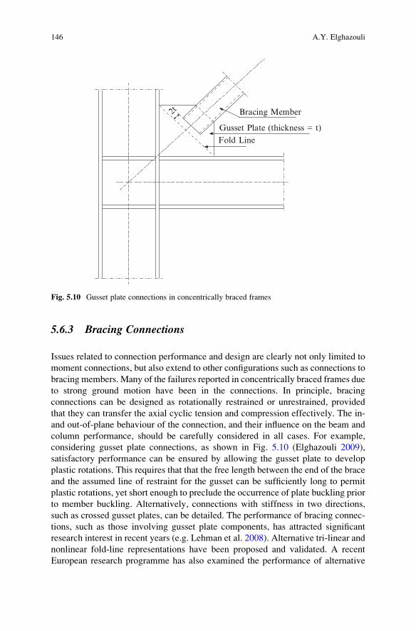
column performance, should be carefully considered in all cases. For example,
considering gusset plate connections, as shown in Fig. 5.10 (Elghazouli 2009),
satisfactory performance can be ensured by allowing the gusset plate to develop
plastic rotations. This requires that that the free length between the end of the brace
and the assumed line of restraint for the gusset can be sufficiently long to permit
plastic rotations, yet short enough to preclude the occurrence of plate buckling prior
to member buckling. Alternatively, connections with stiffness in two directions,
such as crossed gusset plates, can be detailed. The performance of bracing connec-
tions, such as those involving gusset plate components, has attracted significant
research interest in recent years (e.g. Lehman et al. 2008). Alternative tri-linear and
nonlinear fold-line representations have been proposed and validated. A recent
European research programme has also examined the performance of alternative
Bracing Member2t
Gusset Plate (thickness = t)
Fold Line
Fig. 5.10 Gusset plate connections in concentrically braced frames
146 A.Y. Elghazouli

forms of gusset-plate bracing connections and provided recommendations on opti-
mum configurations for use in design (Broderick et al. 2013).
Design examples for bracing-to-gusset plate connections in concentrically and
eccentrically braced frames are given in the AISC Seismic Design Manual (2012),
in accordance with AISC 341 and ASCE7, and typically require many consider-
ations and design checks. In contrast, as for moment connections, the design of
connections between bracing members and beams/columns is only dealt with in a
conceptual manner in EC8. Accordingly, designers can adopt details available from
the literature, or based on prototype testing.
Designing bracing connections in an efficient and practical manner can be
complex and time-consuming, and requires significant expertise (Elghazouli and
Packer 2014). This has led to the development of ‘pre-engineered’ proprietary
solutions using ‘off-the-shelf’ cast steel connections (Herion et al. 2010). A sub-
stantially more compact field-bolted connection is achieved than would otherwise
be possible with typical bolted connections using splice plates. Other proprietary
connections include yielding ‘fuses’ such as the Yielding Brace System (YBS)
(Gray et al. 2014). In this case, dissipation is provided by flexural yielding of parts
of the YBS while the bracing member and other frame elements remain essentially
elastic. Another ‘off-the-shelf’ solution is also provided through Buckling
Restrained Braces which, as noted before, are not currently directly addressed in
EC8. It should be noted that AISC358 is limited to prequalified solutions for steel
moment connections, and does not prequalify connections for braced frames. At
present, ‘pre-engineered’ bracing connections can perhaps be treated in a compa-
rable manner to qualification of custom seismic products which require proof
testing. Overall, compared to self-designed connections, proprietary seismic con-
nections could offer improved performance, additional quality assurance, and the
potential for savings in cost and construction time.
5.7 Concluding Remarks
This paper highlights various issues related to the seismic design of steel and
composite frames that would benefit from further assessment and code develop-
ment, with particular focus on the provisions of EC8. Since the European seismic
code is in general relatively clear in its implementation of the underlying capacity
design principles as well as the purpose of the parameters adopted within various
procedures, its rules can be readily adapted and modified based on new research
findings and improved understanding of seismic behaviour.
Comparison of EC8 provisions with those in AISC in terms of structural
configurations and associated behaviour factors highlights a number of issues that
are worthy of further development. Several lateral resisting systems that are cur-
rently dealt with in AISC are not incorporated in EC8 including steel-truss moment
frames, steel-plate walls and buckling-restrained braces. It is anticipated that these
will be considered in future revisions of the code. Another notable difference is the
5 Seismic Code Developments for Steel and Composite Structures 147

relatively low q assigned to V-braced frames in EC8 compared to AISC, which
highlights the need for further assessment of behaviour factors particularly for
braced and dual frames in EC8, and to extend it to other forms such as ‘zipper’and ‘buckling restrained’ configurations. It is also shown that whilst EC8 typically
adopts the equal-displacement approach for predicting inelastic drift, US provisions
employ specific seismic drift amplification factors. It is however noted that there is
a need for seismic codes to adopt improved prediction methods which account for
earthquake characteristics.
In terms of local ductility, comparison of the width-to-thickness limits in EC8
and AISC reveals considerable differences, particularly in the case of rectangular
and circular tubular members. Since the ductility capacity and susceptibility to
fracture are directly related to the occurrence of local buckling, it seems necessary
to conduct further assessment of the adequacy of Class 1 sections to satisfy the
cyclic demands imposed under prevalent seismic conditions. For composite dissi-
pative sections, the requirements in EC8 for determining the effective width and the
detailing in the slab is intricate, and some pragmatism and simplification in its
application may be necessary, unless the option of ‘disconnection’ is adopted. It isalso noted that allowing DCL or modified-DCL detailing in EC8 for moderate
seismicity, with an appropriate reserve capacity, may be desirable particularly for
special or complex structures.
It is observed that in EC8 the capacity-design application rules for columns
ignore the important influence of gravity loads on the over-strength of beams. This
issue becomes particularly pronounced in gravity-dominated frames or in low-rise
configurations. The extent of the problem depends on the interpretation of the code
and whether Ω is used in isolation or in combination with an additional capacity
design criterion based on a limiting ratio of 1.3 on the column-to-beam capacity.
The above-noted issue becomes more significant in composite moment frames
where relatively large spans are typical. This is also added to the problem of
achieving full beam hinging in dissipative composite frames due to the difference
between the sagging and hogging moment capacities in composite sections.
In order to mitigate the vulnerability of braced frames to the concentration of
inelastic demand within critical storeys, EC8 introduces a 25 % limit on the
maximum difference in brace over-strength (Ωi) within the frame. Detailed studies
show that this may not eliminate the problem and can impose additional design
effort and difficulties in practical design. Instead, this limit can be significantly
relaxed or even removed if measures related to column continuity and stiffness are
incorporated in design. Another issue related to concentrically braced frames is the
lower slenderness limit of 1.3 imposed in EC8 for X-bracing, in order to limit the
compression force in the brace. Satisfying this limit can result in significant
difficulties in practical design. It would be more practical to avoid placing such
limits, yet ensure that forces applied on components other than the braces are based
on equilibrium at the joints, with due account of the relevant actions in compres-
sion. Improved procedures that account for brace slenderness as well as expected
levels of ductility could be adopted.
148 A.Y. Elghazouli
For the purpose of capacity design checks, it is important to determine a realistic
value for the over-strength of steel material. Unlike AISC, EC8 suggests a default
value of 1.25. It is recognised however that the level of over-strength varies
significantly depending on the type and grade of steel, with the over-strength
expected to be more pronounced in lower grades. There seems to be a need for
more reliable guidance in EC8 on the levels and sources of material over-strength
that should be adopted in practice. Another area that requires clarification and
development in EC3 and EC8 is related to the steel material toughness for appli-
cation in seismic design. Specific guidance appears to be needed particularly in
relation to reference temperatures and strain rates that would be appropriate to
employ in seismic design situations.
Apart from over-strength arising from the material, lateral frame over-strength
can be a direct result of design idealisations or the application of drift-related
criteria. A significant design idealisation in concentrically braced frames is related
to the treatment of buckling of the compression braces. Whereas AISC largely
bases the design strength on the brace buckling capacity in compression, EC8
adopts the brace plastic capacity in tension with few exceptions. Whilst both
simplifications lead to frame over-strength, they have directly opposite trends
with respect to the brace slenderness. Depending on the specific design situation
and frame configuration, it may be necessary to estimate either the maximum or
minimum forces attained in compression members in a more realistic manner as
opposed to the idealised approaches currently adopted in seismic codes.
The other key consideration influencing lateral frame over-strength is related to
drift criteria. In comparison with other seismic codes, drift and stability require-
ments in EC8 are significantly more stringent. As a consequence, these checks can
often govern the design, leading to considerable over-strength, especially if a high
‘q’ is assumed. Whereas the presence of over-strength reduces the ductility demand
in dissipative zones, it also affects forces imposed on frame and foundation
elements. A rational application of capacity design necessitates a realistic assess-
ment of lateral capacity after the satisfaction of all provisions, followed by a
re-evaluation of global over-strength and the required ‘q’. Although high ‘q’ factorsare allowed for various frame types in EC8, such a choice is often unnecessary and
undesirable.
In terms of beam-to-column connections, there is clearly a need for a concerted
effort to develop European guidance, in conjunction with the principles of EC8, on
appropriate connection detailing using representative sections, materials and detail-
ing practices. There is also a need for reviewing the design of column panel zones in
moment frames, resulting from the combined application of the rules in EC3 and
EC8. In particular, the definition of the yield point as well as the balance of
plasticity between the panel and connected beams require further consideration.
In general, it seems logical for future activities to promote the development of
‘prequalified’ or ‘pre-engineered’ seismic connections that satisfy the requirements
of EC8, and to provide supporting design procedures and associated simplified
analytical tools. These should not be limited to welded moment connections, but
5 Seismic Code Developments for Steel and Composite Structures 149

should extend to bolted rigid and semi-rigid configurations as well as joints of
bracing members and link zones in braced frames.
Open Access This chapter is distributed under the terms of the Creative Commons Attribution
Noncommercial License, which permits any noncommercial use, distribution, and reproduction in
any medium, provided the original author(s) and source are credited.
References
AISC (2012) Seismic design manual, 2nd edn. American Institute of Steel Construction Inc.,
AISC, Chicago
AISC 341 (2010) Seismic provisions for structural steel buildings. ANSI/AISC 341–10 American
Institute of Steel Construction Inc., AISC, Chicago
AISC 358 (2010) Prequalified connections for special and intermediate steel moment frames for
seismic applications. ANSI/AISC 358–10, American Institute of Steel Construction Inc.,
AISC, Chicago
ASCE7 (2010) ASCE/SEI – ASCE 7–10 – minimum design loads for buildings and other
structures. American Society of Civil Engineers/Structural Engineering Institute, Reston
Broderick BM, Hunt A, Mongabure P, LeMaoult A, Goggins JM, Salawdeh, S, O’Reilly G, Beg D,Moze P, Sinur F, Elghazouli AY, and Plumier A (2013) Assessment of the seismic response of
concentrically-braced frames. SERIES Concluding Workshop, Earthquake Engineering
Research Infrastructures, European Commissions, JRC-Ispra, Italy
Castro JM, Elghazouli AY, Izzuddin BA (2007) Assessment of effective slab widths in composite
beams. J Constr Steel Res 63(10):1317–1327
Castro JM, Davila-Arbona FJ, Elghazouli AY (2008) Seismic design approaches for panel zones in
steel moment frames. J Earthq Eng 12(S1):34–51
Doneux C, Plumier A (1999) Distribution of stresses in the slab of composite steel-concrete
moment resistant frames submitted to earthquake action. Stahlbau 68(6):438–447
ECCS (2013) Assessment of EC8 provisions for seismic design of steel structures. In: Landolfo R
(ed) European convention for constructional steelwork, Brussels
Eder MA, Vollum RL, Elghazouli AY (2012) Performance of ductile RC flat slab-to-steel column
connections under cyclic loading. Eng Struct 36(1):239–257
Elghazouli AY (2003) Seismic design procedures for concentrically braced frames. Struct Build
156:381–394
Elghazouli AY (ed) (2009) Seismic design of buildings to Eurocode 8. Taylor and Francis/Spon
Press, London
Elghazouli AY (2010) Assessment of European seismic design procedures for steel framed
structures. Bull Earthq Eng 8(1):65–89
Elghazouli AY, Packer JA (2014) Seismic design solutions for connections to tubular members. J
Steel Constr 7(2):73–83
Elghazouli AY, Treadway J (2008) Inelastic behaviour of composite members under combined
bending and axial loading. J Constr Steel Res 64(9):1008–1019
Elghazouli AY, Broderick BM, Goggins J, Mouzakis H, Carydis P, Bouwkamp J, Plumier A
(2005) Shake table testing of tubular steel bracing members. Struct Build 158:229–241
Elghazouli AY, Castro JM, Izzuddin BA (2008) Seismic performance of composite moment
frames. Eng Struct 30(7):1802–1819
Elghazouli AY, Kumar M, Stafford PJ (2014) Prediction and optimisation of seismic drift
demands incorporating strong motion frequency content. Bull Earthq Eng 12(1):255–276
Eurocode 3 (2005) Design of steel structures – Part 1.1: General rules and rules for buildings. EN
1993–1: 2005, European Committee for Standardization, CEN, Brussels
150 A.Y. Elghazouli

Eurocode 4 (2004) Design of composite steel and concrete structures – Part 1.1: General rules and
rules for buildings. EN 1994–1: 2004, European Committee for Standardization, CEN,
Brussels
Eurocode 8 (2005) Design of structures for earthquake resistance – Part 1: General rules, seismic
actions and rules for buildings. EN 1998–1: 2004, European Committee for Standardization,
Brussels
FEMA (2000) Federal Emergency Management Agency. Recommended seismic design criteria
for new steel moment-frame buildings. Program to reduce earthquake hazards of steel moment-
frame structures, FEMA-350, FEMA, Washington, DC
Goggins JM, Broderick BM, Elghazouli AY, Lucas AS (2005) Experimental cyclic response of
cold-formed hollow steel bracing members. Eng Struct 27(7):977–989
Gray MG, Christopoulos C, Packer JA (2014) Cast steel yielding brace system (YBS) for
concentrically braced frames: concept development and experimental validations. J Struct
Eng (American Society of Civil Engineers) 140(4):pp.04013095
Herion S, de Oliveira JC, Packer JA, Christopoulos C, Gray MG (2010) Castings in tubular
structures – the state of the art. Struct Build (Proceedings of the Institution of Civil Engineers)
163(SB6):403–415
Kumar M, Stafford PJ, Elghazouli AY (2013) Influence of ground motion characteristics on drift
demands in steel moment frames designed to Eurocode 8. Eng Struct 52:502–517
Lehman DE, Roeder CW, Herman D, Johnson S, Kotulka B (2008) Improved seismic performance
of gusset plate connections. J Struct Eng, ASCE 134(6):890–901
Plumier A, Doneux C, Bouwkamp JG, Plumier C (1998) Slab design in connection zones of
composite frames. Proceedings of the 11th ECEE Conference, Paris
SAC (1995) Survey and assessment of damage to buildings affected by the Northridge Earthquake
of January 17, 1994, SAC95-06, SAC Joint Venture, Sacramento
5 Seismic Code Developments for Steel and Composite Structures 151


![Seismic collapse performance of special moment steel …earthquake.hanyang.ac.kr/journal/2017/[2017]Han et al-Seismic... · Seismic collapse performance of special moment steel frames](https://static.fdocuments.us/doc/165x107/5b8364d47f8b9adc698cfc15/seismic-collapse-performance-of-special-moment-steel-2017han-et-al-seismic.jpg)