Chapter 3. Theory of Operation -...
32
) ) ) Chapter 3. Theory of Operation Contents Manufacturing System Overview Controller . ........ . System Configuration System Data Flow Diagram 2MB Memory .. .. .. . Math Coprocessor ... . Digital Input/Digital Output (DI/DO) Card 4-Port RS-232 Asynchronous Communications Adapter Axis Control Card Disk/Diskette Drives Options ...... . Servo Power Module . Remote Manip Stop Switch Manipulator ..... ... . . Roll-Up Tool (IBM Industrial Computer) Pendant .... ... ... . . . Controller Power-On Sequence Manipulator Power-On Sequence Manipulator Movement Sequence Harmonic Drive .. .... . Return To Home Sequence Home Conditions Overrun Condition .. .. . Gripper Operation . .. . . Controller Digital Input/Digital Output (DI/DO) Power Supplies Controller Servo Power Module Communications Customer Connector (C5) 3-2 3-2 3-3 3-4 3-5 3-5 3-5 3-5 3-6 3-6 3-6 3-7 3-10 3-11 3-13 3-14 3-18 3-20 3-22 3-24 3-25 3-26 3-27 3-28 3-29 3-30 3-30 3-30 3-31 3-33 Chapter 3. Theory or Operation 3-1
Transcript of Chapter 3. Theory of Operation -...

)
)
)
Chapter 3. Theory of Operation
Contents
Manufacturing System Overview Controller . ........ . System Configuration System Data Flow Diagram
2MB Memory . . .. .. . Math Coprocessor ... . Digital Input/Digital Output (DI/DO) Card 4-Port RS-232 Asynchronous Communications Adapter Axis Control Card Disk/Diskette Drives Options ...... .
Servo Power Module . Remote Manip Stop Switch
Manipulator ..... ... . . Roll-Up Tool (IBM Industrial Computer) Pendant .... ... ... . . .
Controller Power-On Sequence Manipulator Power-On Sequence Manipulator Movement Sequence
Harmonic Drive .. .... . Return To Home Sequence Home Conditions Overrun Condition .. .. . Gripper Operation . .. . .
Controller Digital Input/Digital Output (DI/DO) Power Supplies
Controller Servo Power Module
Communications Customer Connector (C5)
3-2 3-2 3-3 3-4 3-5 3-5 3-5 3-5 3-6 3-6 3-6 3-7
3-10 3-11 3-13 3-14 3-18 3-20 3-22 3-24 3-25 3-26 3-27 3-28 3-29 3-30 3-30 3-30 3-31 3-33
Chapter 3. Theory or Operation 3-1
Manufacturing System Overview
Manufacturing System Overview
Controller
3-2 92F2340
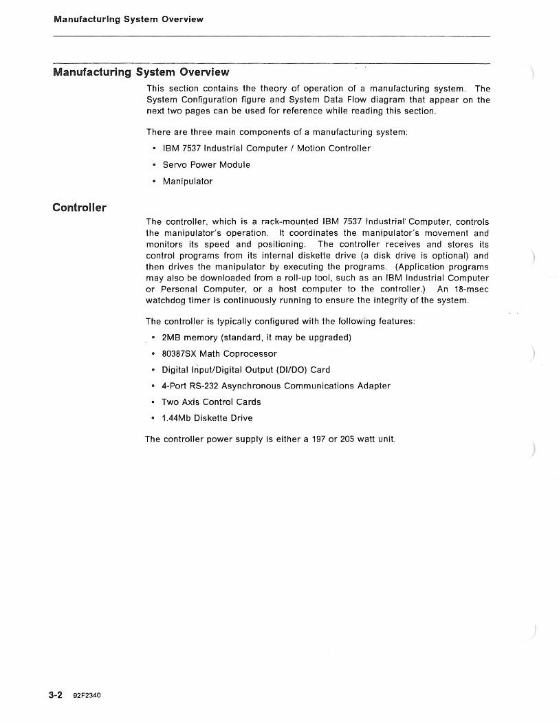
This section contains the theory of operation of a manufacturing system . The System Configuration figure and System Data Flow diagram that appear on the next two pages can be used for reference while reading this section.
There are three main components of a manufacturing system :
o IBM 7537 Industrial Computer I Motion Controller
o Servo Power Module
o Manipulator
The controller, which is a rack-mounted IBM 7537 Industrial· Computer, controls the manipulator's operation . It coordinates the manipulator's movement and monitors its speed and positioning. The controller receives and stores its control programs from its internal diskette drive (a disk drive is optional) and then drives the manipulator by executing the programs. (Application programs may also be downloaded from a roll -up tool, such as an IBM Industrial Computer or Personal Computer, or a host computer to the controller.) An 18-msec watchdog timer is continuously running to ensure the integrity of the system .
The controller is typically configured with the following features :
o 2MB memory (standard, it may be upgraded)
o 80387SX Math Coprocessor
o Digital Input/Digital Output (DilDO) Card
o 4-Port RS-232 Asynchronous Communications Adapter
o Two Axis Control Cards
o 1.44Mb Diskette Drive
The controller power supply is either a 197 or 205 watt unit.
)
)

System Configuration
)
)
Pendant
Manufacturing System Overview
Industrial Computer (controller)
flgggg g 6~)11 NI~IFmliNlllmlUUI Mlfi!IM~IUNil'ml~
servo power module
Chapter 3. Theory of Operation 3-3

Manufacturing System Overview
System Data Flow Diagram
CONTROLLER SPM
~: .__Op_P_:_r_:t_r o_:_u_:_:_lY_e_l_, Power Supply
DDA > Manipulator Mother Board > Interface <
3-4 92F2340
Math Co-Proc ...--->
<l ,.->
I-
Theta 1 1-
(feedback) <-
Theta 2 1-
AC Card 1
Z Axis 1-
(feedback) <-
Roll 1-
AC Card 2
48 DI/DO Card < (3 max)
4 Port Card (2 max)
Ports I 1 thru 8
------------------I v
HOST or
ROLL UP
I
Board <-
Th 1 <-
Servo Amp 1
l Th
Servo Amp 2
Z Axis <-
Servo Amp 3
Roll
Servo Amp 4
p E
X (SPM)
I v
STOP
64 CHAR DISPLAY
N D
A N
T
<-
MANIPULATOR
t-> Motor
Encoder/Sensor
> Motor t-
Encoder/Sensor
> Motor t-:
Encoder/Sensor
'-: > Motor
Encoder/Sensor
> Fixtures
- >
and Feeders
Valves ·, Alarms,
Etc.
)
)
Manufacturing System Overview
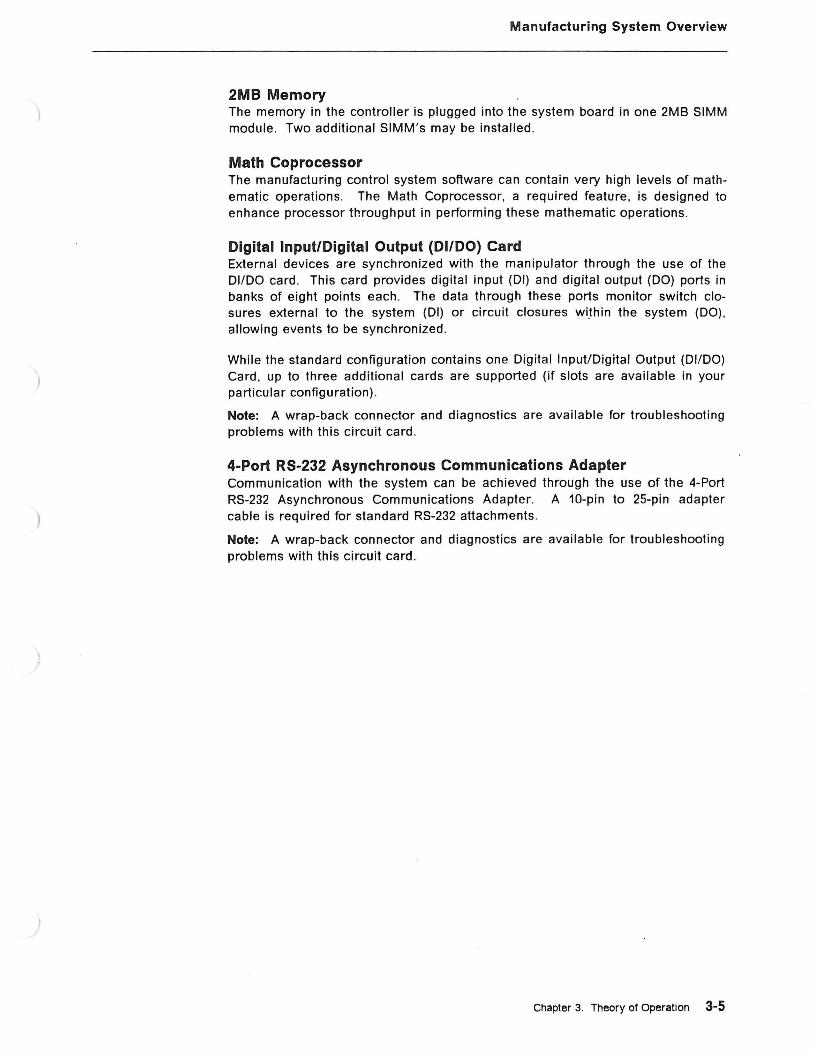
2MB Memory The memory in the controller is plugged into the system board in one 2MB SIMM module. Two additional SIMM's may be installed.
Math Coprocessor The manufacturing control system software can contain very high levels of mathematic operations. The Math Coprocessor, a required feature, is designed to enhance processor throughput in performing these mathematic operations.
Digital Input/Digital Output (DilDO) Card External devices are synchronized with the manipulator through the use of the DilDO card . This card provides digital input (DI) and digital output (DO) ports in banks of eight points each . The data through these ports monitor switch closures external to the system (DI) or circuit closures wi.thin the system (DO), allowing events to be synchronized .
While the standard configuration contains one Digital Input/Digital Output (DI/DO) Card, up to three additional cards are supported (if slots are available in your particular configuration) .
Note: A wrap-back connector and diagnostics are available for troubleshooting problems with this circuit card .
4-Port RS-232 Asynchronous Communications Adapter Communication with the system can be achieved through the use of the 4-Port RS-232 Asynchronous Communications Adapter. A 10-pin to 25-pin adapter cable is required for standard RS-232 attachments.
Note: A wrap-back connector and diagnostics are available for troubleshooting problems with this circuit card.
Chapter 3. Theory of Operation 3-5

Manufacturing System Overview
3-6 92F2340
Axis Control Card Direct motion control of the manipulator axes movement is achieved through the use of two Axis Control Cards. Each card controls two axes and contains directaccess memory and read-only memory to provide ~ intelligence" by continuously monitoring the motion of the manipulator. As part of this "intelligence,~ at each power up time, a diagnostic routine performs a basic checkout of the Axis Control Cards ' circuitry. This provides integrity for a manipulator startup.
Disk/Diskette Drives The standard disk/diskette device is a single 1.44 megabyte diskette drive. One additional diskette drive (either another 1.44Mb drive, a 1.2Mb drive, or a 2.88Mb drive) and/or a 40Mb or 80Mb fixed disk drive may be installed .
Note: A maximum of two diskette drives and one disk drive is supported .
In keeping with the maintenance philosophy, diagnostics are provided for all standard and optional disk/diskette drives.
Options With the standard 7537 Motion Controller configuration , one additional card slot is available for options. Diagnostics are provided for all supported options. For a list of supported options , refer to the "Specifications" section of this manual.
)
)
)

)
Manufacturing System Overview
Servo Power Module
The Servo Power Module (SPM) is a modularized interface between the manufacturing system controller (7537) and the manipulator. It provides pulse-width modulated drive power for the manipulator motors, de power for various functions , and processing and distribution of manipulator and pendant signals .
The Servo Power Module typically contains:
• Four servo amplifier cards
• A pluggable power supply
• A manipulator interface board
Various other electronic components that help to control the powering and motion functions of the manipulator.
• An operator control panel
Aside from the controls on the operator control panel, a remote Manipulator Stop switch can be connected for controlling the manipulator. An optional pendant device can then be attached to the Servo Power Module via the remote Manip Stop switch cable. The pendant is used to "teach" points on the system , to display error messages, and to execute diagnostics.
Each of the servo amplifier cards provides motion control for one axis on the manipulator. The output of each card drives one servo motor.
All servo amplifier cards are interchangeable without modification for troubleshooting . No adjustments are required. In addition, each servo amplifier card is an individual Field Replaceable Unit (FRU) ; that is , they contain no individually replaceable components (except a fuse) .
The power supply is pluggable as a circuit card and is in the same card cage as the servo amplifier cards. Like the four servo amplifier cards , the power supply is a FRU and it requires no adjustments .
The manipulator interface board is mounted in the the Servo Power Module. The board contains the interface circuitry for inputs and outputs between the controller and the manipulator.
Other miscellaneous electronics incorporated in the Servo Power Module circuitry are :
• Capacitors • Coils • Relays • Transformers .
Chapter 3. Theory of Operation 3-7
Manufacturing System Overview
3-8 92F2340
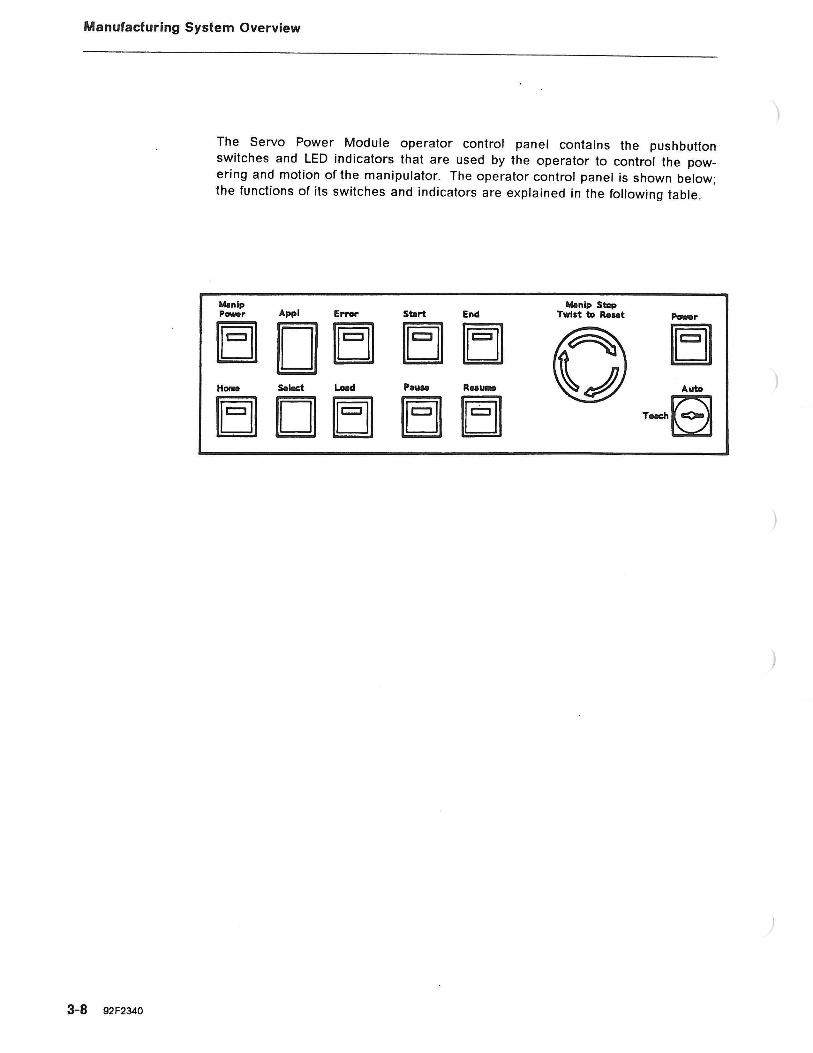
The Servo Power Module operator control panel contains the pushbutton switches and LED indicators that are used by the operator to control the powering and motion of the manipulator. The operator control panel is shown below; the functions of its switches and indicators are explained in the following table.
M.nlp Power Appl Error Sbrt End
B D IE] EJJ EJJ Home S.lct Loed Pauae R .. u ...
E] D EJ1 E] [E]
)

)
)
)
Switch/ Indicator
Manlp Power
Appl
Error
Start
End
Manip Stop
Power
Home
Select
Load
Pause
Resume
Auto/Teach
Manufacturing System Overview
Function
This LED blinks when system power is on. This blinking prompts the operator to press the button, thus supplying de voltages to the manipulator servo motors (that is , powering the manipulator). While manipulator power is on , the LED stays lit.
This single digit read-out gives a number from 0 to 7, denoting which application program is currently loaded . The application program , and consequently this indicator, are stepped with the Select pushbutton . After power on , the number indicated should be a 1.
When on, this LED indicates that an error has occurred. If a pendant is attached , the error will be displayed on the pendant after the Recall Error button is pressed.
This button starts an application program from the beginning .
This button stops the current application program at the end of the program . It flashes until the end is reached and then goes on solid.
This large red latching pushbutton immediately removes voltages to the manipulator servo motors and to the dynamic brake holding relay, causing the manipulator to stop. To reset, simply twist the switch cap clockwise.
This LED lights to indicate that low voltage de is active.
This LED/pushbutton allows the operator to send the manipulator to the "home" position . When the LED is on solid , the manipulator has been homed.
This pushbutton is used to step through the application programs numbered 1 through 7. The current program's designation is indicated by the single digit Appl display.
This function loads an application program into memory. The designation of the program that is to be loaded is indicated by the single digit Appl display. The Load LED flashes while the program is loading , and is on solid when loading has completed successfully.
This LED/pushbutton can be used to cause a stop at the next PAUSE instruction in the application program. It flashes while a pause is pending and goes on solid when the pause has occurred .
After an exception has stopped the program, this button causes the Error LED to be turned off and the Start-up sequence to be rerun. Following Start-up, or after a pause or end, pressing this button will, if possible, resume program execution where it was halted.
l"his key-operated switch selects either Auto mode or Teach mode. Auto mode allows program selection and execution . Teach mode allows the "teach " function and defaults to a very low speed .
Chapter 3. Theory of Operation 3-9

Manufacturing System Overview
3-1 0 92F2340
Remote Manip Stop Switch
A large red latching Manip Stop switch attaches to the Servo Power Module via a cable . This switch performs the same function as the Manip Stop switch on the operator panel ; that is , it immediately removes voltages to the manipulator servo motors and to the dynamic brake holding relay, causing the manipulator to stop. To reset this latching switch, simply twist the switch cap clockwise .
The pendant, a hand-held multi-purpose key entry/display device, also attaches to the Servo Power Module via the cable to the remote Manip Stop switch . The pendant is used primarily for the "teach " function , but it is also required for maintenance to retrieve error codes and select diagnostics. (For information about the pendant' s keybuttons , indicators, and other features , refer to " Pendant " on page 3-14.)
)
)
)
)
)
Manufacturing System Overview
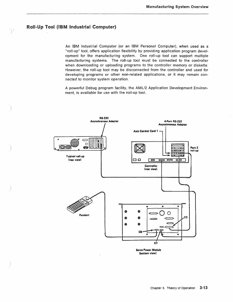
Roll-Up Tool (IBM Industrial Computer)
An IBM Industrial Computer (or an IBM Personal Computer). when used as a "roll-up" tool , offers application flexibility by providing application program development for the manufacturing system. One roll-up tool can support multiple manufacturing systems. The roll-up tool must be connected to the controller when downloading or uploading programs to the controller memory or diskette. However, the roll-up tool may be disconnected from the controller and used for developing programs or other non-related applications, or it may remain connected to monitor system operation .
A powerful Debug program facility, the AML/2 Application Development Environment, is available for use with the roll-up tool.
Typical roll-up lr•rwiewl
Pendllnt
RS-232 Asynchronous Adllpur
0
0
•
Axil Control C.rd 1
a a Controller
Cr .. r wiewl
•
4-Port RS·232 Asynchronous Ad1pur
• • • -c=:Jo 0 0 • C3
• Cl
C7
Servo Po-r Module Cbottom wiewl
Chapter 3. Theory of Operation 3·13
Manufacturing System Overview
Pendant
3-14 92F2340
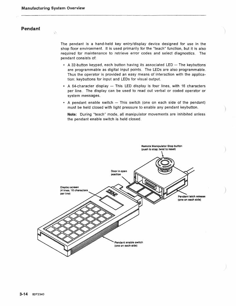
The pendant is a hand-held key entry/display device designed for use in the shop floor environment. It is used primarily for the "teach" function. but it is also required for maintenance to retrieve error codes and select diagnostics. The pendant consists of:
• A 32-button keypad, each button having its associated LED - The keybuttons are programmable as digital input points . The LEOs are also programmable. Thus the operator is provided an easy means of interaction with the application : keybuttons for input and LEOs for visual output.
• A 64-character display - This LED display is four lines, with 16 characters per line . The display can be used to read out verbal or coded operator or system messages.
• A pendant enable switch - This switch (one on each side of the pendant) must be held closed with light pressure to enable any pendant keybutton .
Note: During "teach" mode, all manipulator movements are inhibited unless the pendant enable switch is held closed.
Display screen (4 lines, 16 characters per line)
Door In open poaltlon
Remota Manipulator Stop button (push to stop; twist to reset)
Pendant enable switch (one on each side)
)
)
)
)
Manufacturing System Overview
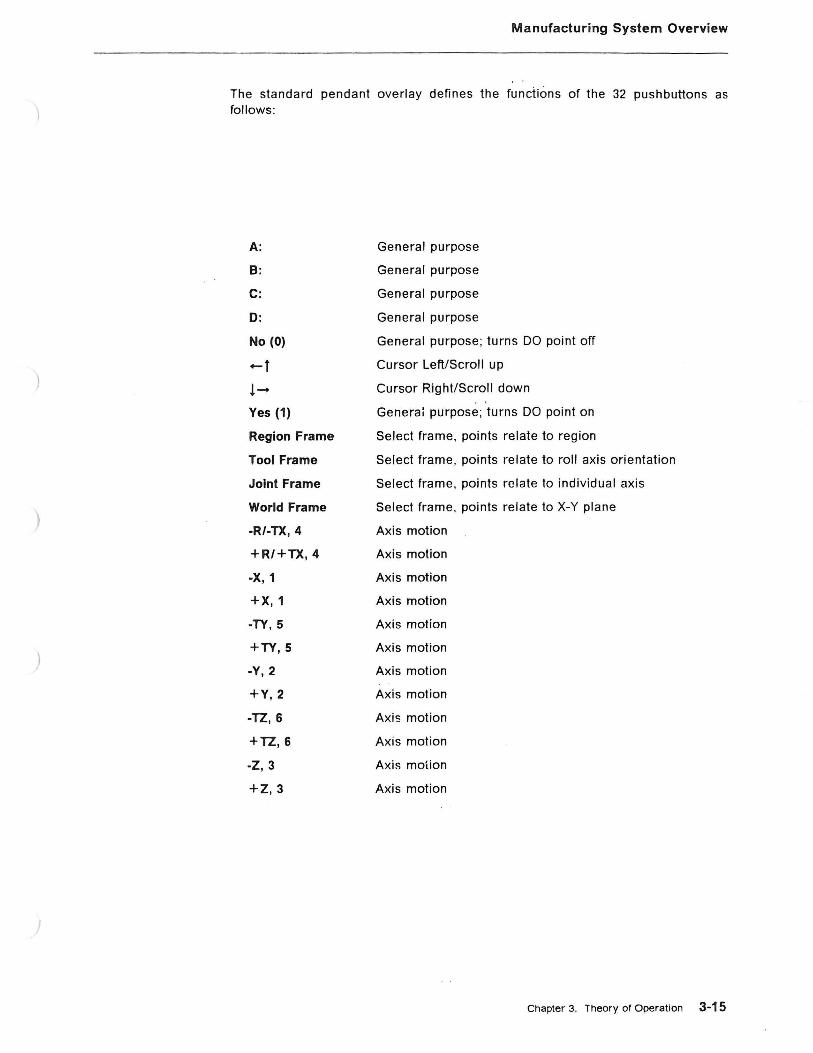
The standard pendant overlay defines the functions of the 32 pushbuttons as follows:
A: General purpose
B: General purpose
C: General purpose
D: General purpose
No (0) General purpose; turns DO point off
-t Cursor Left/Scroll up
!- Cursor Right/Scroll down
Yes (1) Generai purpose; turns DO point on
Region Frame Select frame , points relate to region
Tool Frame Select frame , points relate to roll axis orientation
Joint Frame Select frame, points relate to individual axis
World Frame Select frame, points relate to X-Y plane
-R/-TX, 4 Axis motion
+R/+TX, 4 Axis motion
-X, 1 Axis motion
+X, 1 Axis motion
-TY, 5 Axis motion
+TY, 5 Axis motion
-Y, 2 Axis motion
+Y, 2 Axis motion
-TZ, 6 Axis motion
+TZ, 6 Axis motion
-Z, 3 Axis motion
+Z, 3 Axis motion
Chapter 3. Theory or Operation 3-15
Manufacturing System Overview
3-16 92F2340
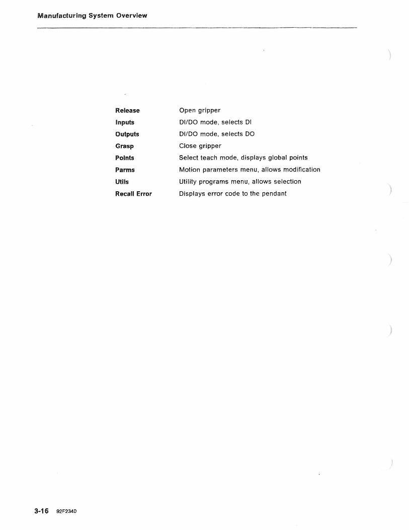
Release
Inputs
Outputs
Grasp
Points
Parms
Utlls
Recall Error
Open gripper
DI/DO mode, selects Dl
DI/DO mode, selects DO
Close gripper
Select teach mode, displays global points
Motion parameters menu, allows modification
Util ity programs menu, allows selection
Displays error code to the pendant
)
)

I~ 1-==========!'111
uuuu bJGJ[JbJ Fl~~~ ~~~l!;U
~~~uu bJbJU~ bJbJUr:J b]b]b]b] b]bJbJ~
Manufacturing System Overview
Chapter 3. Theory of Operation 3-17

Controller Power-On Sequence
Controller Power-On Sequence
3-18 92 F2340
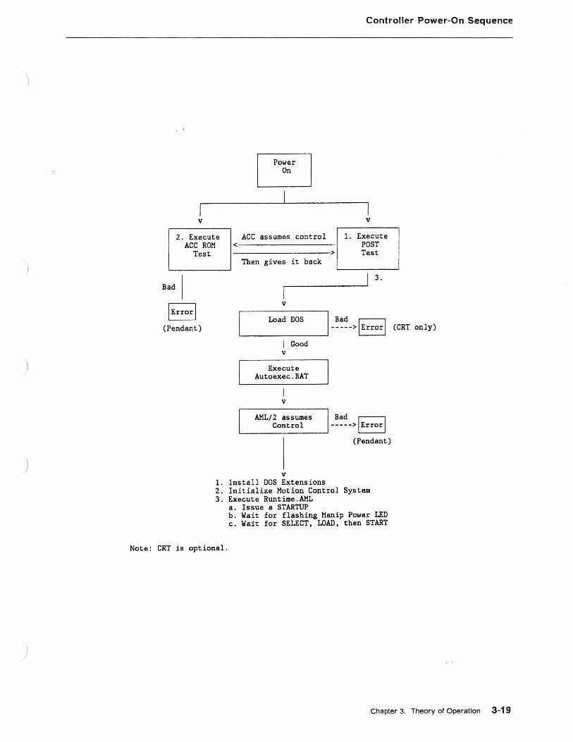
1. The controller circuit breaker enables the ac circuit to the fans and de power supply.
2. The Power-On Self-Test (POST) and the Axis Control Card ROM tests execute. The POST test completes first and the Axis Control Card ROM assumes control. Because the Axis Control Card is " intelligent" (and therefore unique to this manufacturing system) , certain hardware and software functions must be checked to ensure the integrity of the system.
3. After the Axis Control Card ROM tests are completed, DOS is loaded . Errors and exceptions are presented to the Servo Power Module operator panel Error LED.
4. AUTOEXEC.BAT file is executed.
5. AML/2 assumes control and:
a. Installs DOS extensions
b. Initializes Motion Control System (MCS)
c. Executes RUNTIME.AML which allows a manipulator STARTUP.
)
)
v
2 . Execute ACC ROM
Test
I Error I (Pendant)
~ L:_j
v
Controller Power-On Sequence
1. Install DOS Extensions 2. Initialize ~lotion Control System 3. Execute Runtime.AML
a. Issue a STARTUP b. Wait for flashing Manip Power LED c. Wait for SELECT, LOAD, then START
Note: CRT is optional .
Chapter 3. Theory of Operation 3-19

Manipulator Power-On Sequence
Manipulator Power-On Sequence
3-20 92F2340
1. With the AML/2 Manufacturing Control System in the diskette drive, switch on the controller and Servo Power Module Power.
2. This will load the manufacturing system control program (for example , AML/2) . (The 18-msec watchdog timer is active . Thus every 18 msec, the entire system is scanned for interrupts, conditions , and errors .)
3. Reset the Manip Stop pushbutton if it has been latched .
4. The AML/2 system will issue a STARTUP.
5. Press the flashing Manip Power LED/pushbutton on the ~ervo Power Module operator panel.
6. Power is presented and a move sequence is executed on all axes. If the move sequence is successful , the Manip Power LED stays on; otherwise the ) Error LED illuminates .
7. Press the Home pushbutton on the Servo Power Module operator panel.
8. If the manipulator homes correctly, the Home LED stays on.
9. An application, teach, or diagnostic function can now be initiated .

)
)
Manipulator Power-On Sequence
Controller, SPH power
Good
AHL/2 Program Active
18 msec timer running
HOST or --->
Roll up
press
press
Executes at ------------------------> slow speed
Initiate 'TEACH'
v
STOP restored
'STARTUP' COIIIIIIand
v
MANIP POWER flashing
v
Manipulator Pow'!lr Good
I Yes v
HOVE Sequence
Good
I Yes v
HOME
v
HOME Sequence
Good
I Yes v
Initiate Diagnostics
Runtime.AHL <--- or
Application
No ------->1 Error
--~~--->1 Error
--~~--->1 Error
Application Program
Chapter 3. Theory of Operation 3-21

Manipulator Movement Sequence
Manipulator Movement Sequence
3-22 92F2340
The de servo motors are pulse driven by pulse-width modulation . There are 500 timing pulses (windows) per revolution and one index pulse (window) per revolution . The 500 timing pulses and one index pulse from the encoder provide position and speed information to the Axis Control Cards.
Each timing pulse (window) is read by two photocells (A and 8), and they are only on together for 1/4 of each encoder pulse. These two signals are monitored
· by the Axis Control Cards under control of the AML/2 software, and provide a resolution just under .002 inch.
The index pulse allows the establishment of a "home" position . If the home sensor is covered , then the next index pulse will be the home position for that axis .
The index is also used to ensure a proper count of 500 timing pulses per revolution . The index pulse (I) is monitored by a single photocell.
If the source of the move is one of the manual axis motion keys on the pendant, all joints are allowed to move only at a very slow speed .
If the move is under the control of the application program , the following sequence takes place:
1. The servo amplifier card receives input from the Axis Control Card and drives the servo motor at the proper speed and direction .
2. The Axis Control Card compares "position" (P) with "goal" (G) and sends the proper control voltage to the servo amplifier card .
3. The Axis Control Card receives instructions and calculates the "goal. "
)

)
)
Manipulator Movement Sequence
The following figure shows a closed servo loop circuit.
CONTROLLER SPH MANIPULATOR
AML/2 or
APPLICATION
v I (G)
(P) position/speed <-------------------------------r.-.
AC Cards (2) <:--------,
AML/2 or
APPLICATION
4 Port Card
(2)
Ports I 1 thru 8
v
HOST or
ROLL UP
Op Panel
'HOHE'
Servo > Amp
Cards (4)
A B
I Encoder
Servo 'motor
Chapter 3. Theory of Operation 3-23
Manipulator Movement Sequence
Harmonic Drive
3-24 92F2340
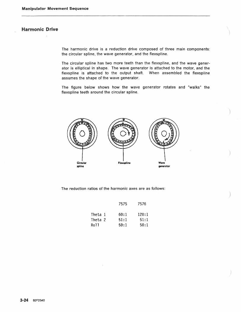
The harmonic drive is a reduction drive composed of three main components : the circular spline, the wave generator, and the flexspline .
The circular spline has two more teeth than the flexspline, and the wave generator is elliptical in shape . The wave generator is attached to the motor, and the flexspline is attached to the output shaft. When assembled the flexspline assumes the shape of the wave generator.
The figure below shows how the wave generator rotates and "walks" the flexspline teeth around the circular spline.
Circuler splint
Fluspl ine W 1V1
gentrltor
The reduction ratios of the harmonic axes are as follows :
7575 7576
Theta 1 60:1 120:1 Theta 2 51:1 51:1 Roll 50:1 50:1
)
)
)
)
Manipulator Movement Sequence
Return To Home Sequence
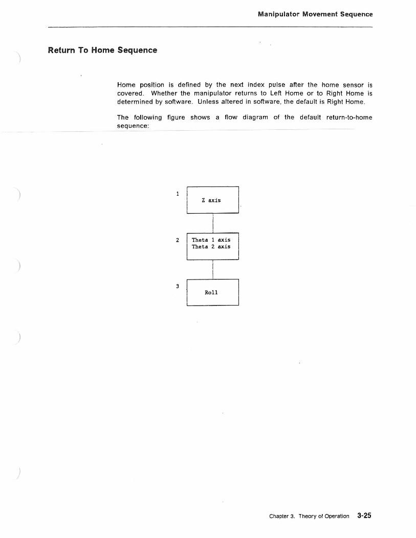
Home position is defined by the next index pulse after the home sensor is covered . Whether the manipulator returns to Left Home or to Right Home is determined by software. Unless altered in software, the default is Right Home.
The following figure shows a flow diagram of the default return-to-home sequence:
1 z axis
2 Theta 1 axis Theta 2 axis
3 Roll
Chapter 3. Theory of Operation 3-25

Manipulator Movement Sequence
Home Conditions
3-26 92F2340
There are two Theta 1 and Theta 2 home positions on the 7575 and 7576 Manipulators: Left Home and Right Home. Whether the manipulator returns to Left Home- or to Right Home is determined by software. Unless altered in software, the default is Right Home.
The Roll motion of the Z-shaft has only one home position . Likewise, the vertical travel of the Z-shaft has only one home position , the extreme up position.
When the Home LED on the Servo Power Module is illuminated, the manipulator has been homed. The figure below shows the home sensors .
MANIPULATOR
Theta 1 + (right) Home
Theta 1 -(left) Home
SPH CONTROLLER
----> ------
I ---->
~..-.Th_<H_~!_i_:_!_/__.----> -----L ______ s ca,d 1
Theta 2 -(left) Home
I ----> ------
Q:J-> -----~--------- ->8CC ---------- -----> Card 2
z Home 1-----> ------
Sensor
(HIB Board)
)
)
)
)
Manipulator Movement Sequence
Overrun Condition
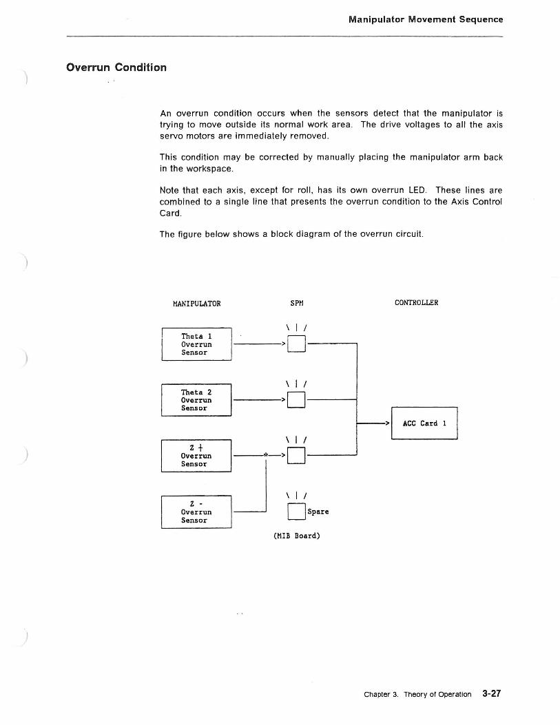
An overrun condition occurs when the sensors detect that the manipulator is trying to move outside its normal work area. The drive voltages to all the axis servo motors are immediately removed.
This condition may be corrected by manually placing the manipulator arm back in the workspace .
Note that each axis, except for roll , has its own overrun LED . These lines are combined to a single line that presents the overrun condition to the Axis Control Card.
The figure below shows a block diagram of the overrun circuit.
MANIPULATOR SP~I CONTROLLER
\ I I Theta 1 >D Overrun Sensor
\ I I Theta 2 >D Overrun Sensor >a
\ I I z + *->D Overrun
Sensor
J \ I I z -
Ospare Overrun Sensor
(MIB Board)
Chapter 3. Theory of Operation 3-27
Manipulator Movement Sequence
Gripper Operation
3-28 92F2340
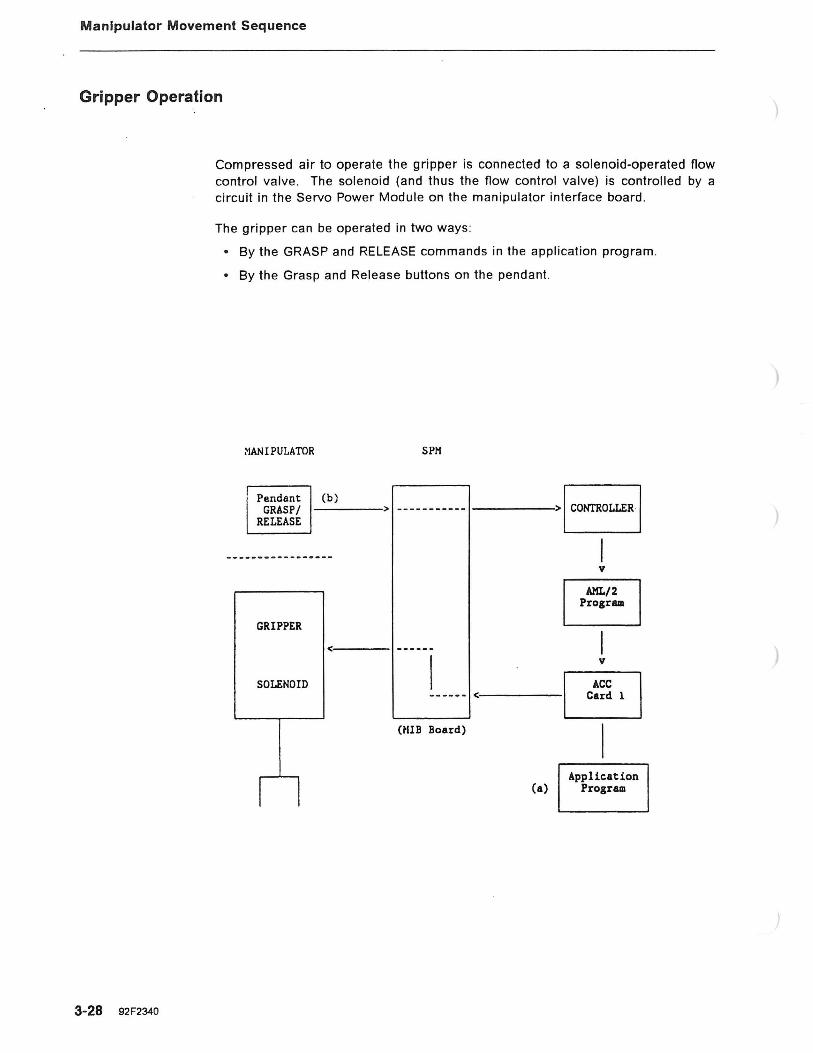
Compressed air to operate the gripper is connected to a solenoid-operated flow control valve . The solenoid (and thus the flow control valve) is controlled by a circuit in the Servo Power Module on the manipulator interface board.
The gripper can be operated in two ways :
• By the GRASP and RELEASE commands in the application program.
• By the Grasp and Release buttons on the pendant.
~IANIPULATOR SPM
Pendant (b) EJ GRASP/ ---> ---------- - -----> CONTROLLER
RELEASE
GRIPPER
<:----1
SOLENOID
I I
HUB Board)
v
AHL/2 Progr8111
v
Application (a) Progr8111
)
)
)
Digital Input/Digital Output
Controller Digital Input/Digital Output (DilDO)
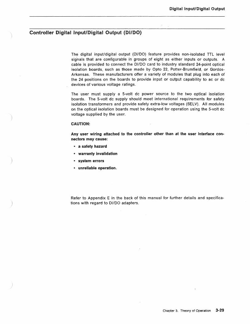
The digital input/digital output (DI/DO) feature provides non-isolated TTL level sig.nals that are configurable in groups of eight as either inputs or outputs. A cable is provided to connect the DilDO card to industry standard 24-point optical isolation boards, such as those made by Opto 22, Potter-Brumfield, or GordosArkansas . These manufacturers offer a variety of modules that plug into each of the 24 positions on the boards to provide input or output capability to ac or de devices of various voltage ratings.
The user must supply a 5-volt de power source to the two optical isolation boards. The 5-volt de supply should meet international requirements for safety isolation transformers and provide safety extra-low voltages (SELV) . All modules on the optical isolation boards must be designed for operation using the 5-volt de voltage supplied by the user.
CAUTION:
Any user wiring attached to the controller other than at the user Interface connectors may cause:
• a safety hazard
• warranty invalidation
• system errors
• unreliable operation.
Refer to Appendix E in the back of this manual for further details and specifications with regard to DilDO adapters .
Chapter 3. Theory of Operation 3·29

Power Supplies
Power Supplies
Controller The IBM 7537 Industrial Computer contains either a 197 or 205 wat1 power supply that furnishes ±5 Vdc, and± 12 Vdc . The power outputs are distributed amoung the system components, such as, the the system board , fan, and disk/diskette drives.
Servo Power Module
3-30 92F2340
The Servo Power Module contains two power supplies . The low voltage power supply is a pluggable unit and furnishes +5 Vdc, ±15 Vdc, and +24 Vdc. The main buss power supply is a standalone power supply. that furnishes high voltage for the manipulator servo motors only.
)

Communications
)
Communications
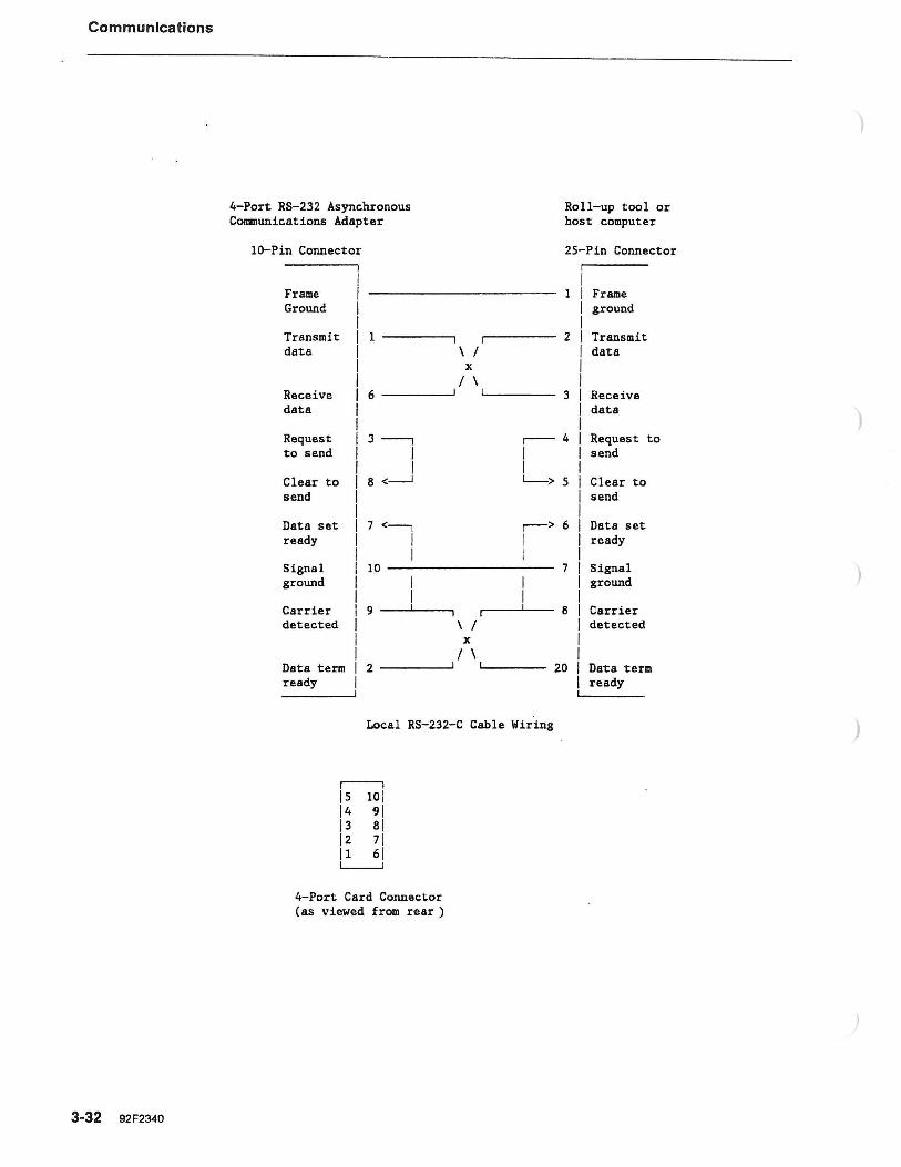
Communication to the controller is established through the 4-Port RS-232 Asynchronous Communications Adapter. This card contains four separate communication ports and is fully programmable. Options, such as baud rate. start and stop bits , data bits , and parity are set by the user with the AMU2 programming facility. The roll-up/host computer cable adapts the 10-pin connector to a standard EIA RS-232-C communication connector.
One 4-Port card {ports 1 - 4) is standard on a manufacturing system ; a second 4-Port card (ports 5 - 8) may be installed.
The following figures show a block diagram of the communications data now, pin assignments, and typical hook-up.
USER DEVICES
HOST or
Roll Up
COt-.'TROLLER
RS RS 232C <:------> 232C
v
RS 232C
Other Devices
4 Port Card
(max 2)
Chapter 3. Theory of Operation 3-31
Communications
3-32 92F2340
4-Port RS-232 Asynchronous Communications Adapter
lG-Pin Connector
Frame Ground
Transmit data
Receive data
Request to send
Clear to send
Data set ready
Signal ground
Carrier detected
1------,
6
3 ---"-1
I I
8 <___j
7<--, I I
10
9
Data term 2 ------' ready
\ I X
I \
\ I X
I \
Roll-up tool or host computer
25-Pin Connector
1 Frame ground
2 Transmit data
3 Receive data
r--4 Request to I send I L___> 5 Clear to
send
r-> 6 Data set I ready I
7 Signal ground
8 Carrier detected
'----- 20 Data term ready
Local RS-232-C Cable Wiring
r--1 15 101 14 91 13 Bl 12 71 ll 61 L-.1
4-Port Card Connector (as viewed from rear )
)
)

)
)
)
Customer Connector (CS)
Customer Connector (CS) Customer connector CS on the bottom of the Servo Power Module provides the electrical connection for optional safety and convenience functions .
• Pins 1 and 2 on connector CS allow an extension of the manipulator stop circuit. Thus a safety zone can be established around the manipulator by installing intrusion warning devices between pins 1 and 2. User contacts should be rated for 24 Vdc at 20 mA minimum.
Note: If no intrusion device is installed, pins 1 and 2 must be jumpered to power on the manipulator.
• Pins 3 and 4 on connector CS allow a "Manipulator Power On" indicator to be installed near the workspace . A contact set on the power sequencing relay (CR1) completes the circuit between pins 3 and 4 when manipulator power is applied. Thus , warning signals can be installed between pins 3 and 4 to indicate when manipulator power is on , making manipulator movement possible at any time. This contact set is rated for 30 Vdc at 2 A maximum.
• Pins 5 and 6 on connector CS may be used to connect a remote Manipulator Power switch. That remote switch would serve the same function as the Manipulator Power pushbutton on the Servo Power Module operator panel. User contacts should be rated for 24 Vdc at 30 mA minimum.
Note: The remote Manipulator Power feature is disabled when the Auto/Teach keyswitch is in the Teach position .
• Pins 7, 8, and 9 are not used.
devices
Relay energized by intrusion device
Manipulator power warning light
Safety mat
-~-
Remote Manipulator _j PowerOn l Switch
cs connector
Chapter 3. Theory of Operation 3-33

Customer Connector (CS)
)
)
)
3-34 92F2340