Chapter 3 Methods of Analysis 1 Copyright © The McGraw-Hill Companies, Inc. Permission required for...
48
Chapter 3 Methods of Analysis 1 Copyright © The McGraw-Hill Companies, Inc. Permission required for reproduction or display.
-
Upload
elinor-mcdaniel -
Category
Documents
-
view
243 -
download
5
Transcript of Chapter 3 Methods of Analysis 1 Copyright © The McGraw-Hill Companies, Inc. Permission required for...
Chapter 3Methods of Analysis
1
Copyright © The McGraw-Hill Companies, Inc. Permission required for reproduction or display.

Methods of Analysis - Chapter 3
3.1 Introduction Nodal analysis.3.2 Nodal analysis with dependent sources.3.3 Nodal analysis with supernode.3.4 Mesh analysis.3.5 Mesh analysis with dependent sources.3.6 Mesh analysis with supermesh 3.7 Source transformation3.8 Norton and Thevenin equivalent circuit3.9 Maximum power transfer and
superposition
2
3
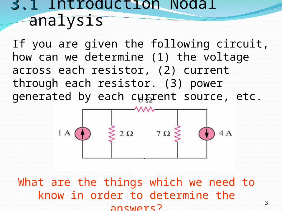
What are the things which we need to know in order to determine the answers?
3.1 3.1 Introduction Nodal analysisIf you are given the following circuit, how can we determine (1) the voltage across each resistor, (2) current through each resistor. (3) power generated by each current source, etc.

Things we need to know in solving any resistive circuit with current and voltage sources only:
4
How should we apply these laws to determine the answers?
• Kirchhoff’s Current Laws (KCL)
• Kirchhoff’s Voltage Laws (KVL)
• Ohm’s Law
3.1 3.1 Introduction Nodal analysis.

Nodal Analysis (1)
5
It provides a general procedure for analyzing circuits using node voltages as the circuit variables.
Example 1
3
Nodal Analysis (2)
6
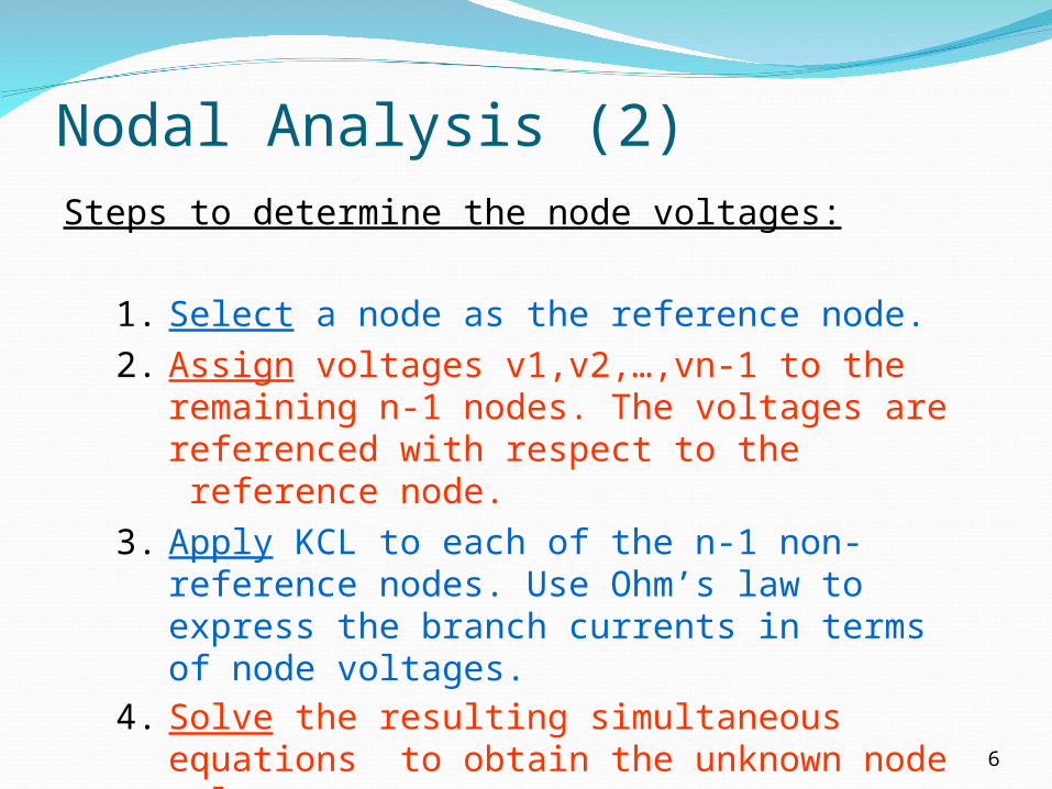
Steps to determine the node voltages:
1. Select a node as the reference node.2. Assign voltages v1,v2,…,vn-1 to the
remaining n-1 nodes. The voltages are referenced with respect to the reference node.
3. Apply KCL to each of the n-1 non-reference nodes. Use Ohm’s law to express the branch currents in terms of node voltages.
4. Solve the resulting simultaneous equations to obtain the unknown node voltages.
Nodal Analysis (3)
7
v1 v2
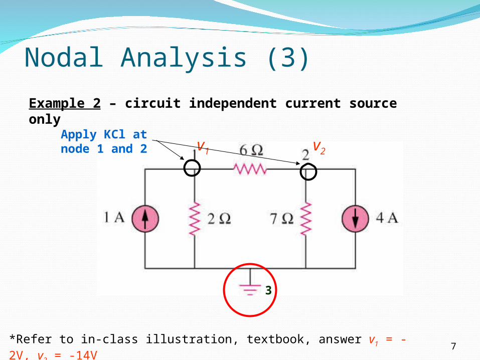
Example 2 – circuit independent current source only
3
*Refer to in-class illustration, textbook, answer v1 = -2V, v2 = -14V
Apply KCl at node 1 and 2

8

2 method to solve1 : Elimination technique2 : Cramer’s Rule
9
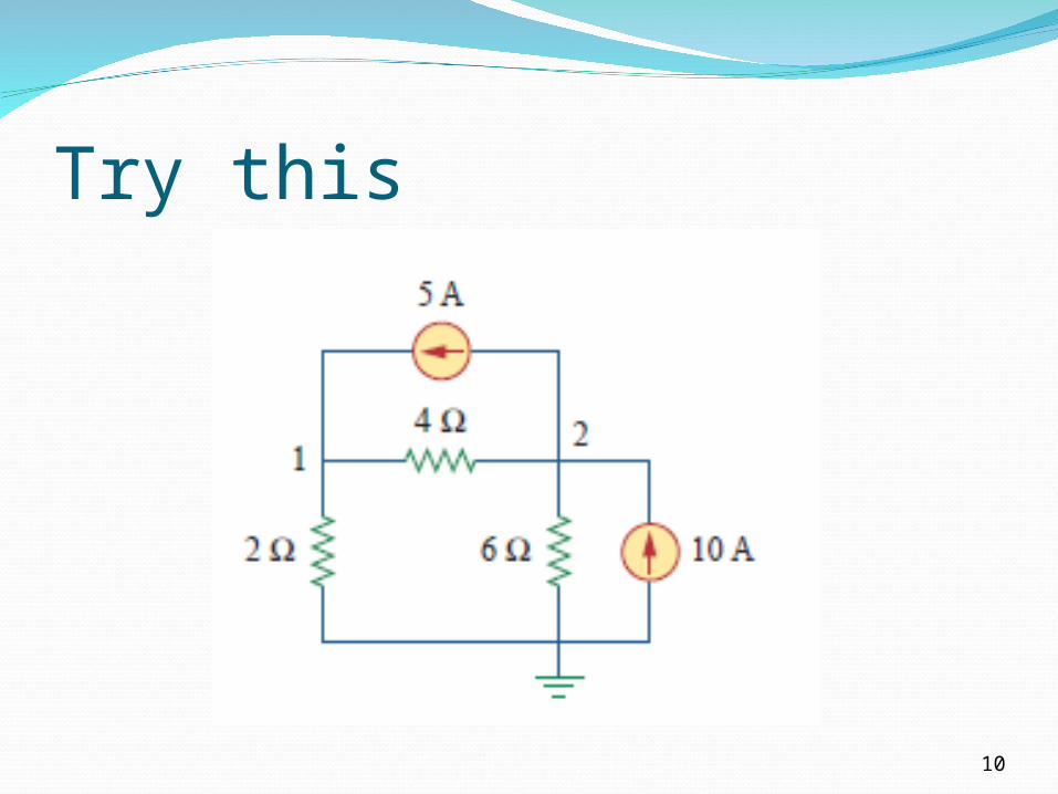
Try this
10

3.2 Nodal Analysis with dependent Source
11
Example 3 – current with dependant current source
answer v1= 4.8V, v2 = 2.4V, v3 = -2.4V
Nodal Analysis with Voltage Source
12
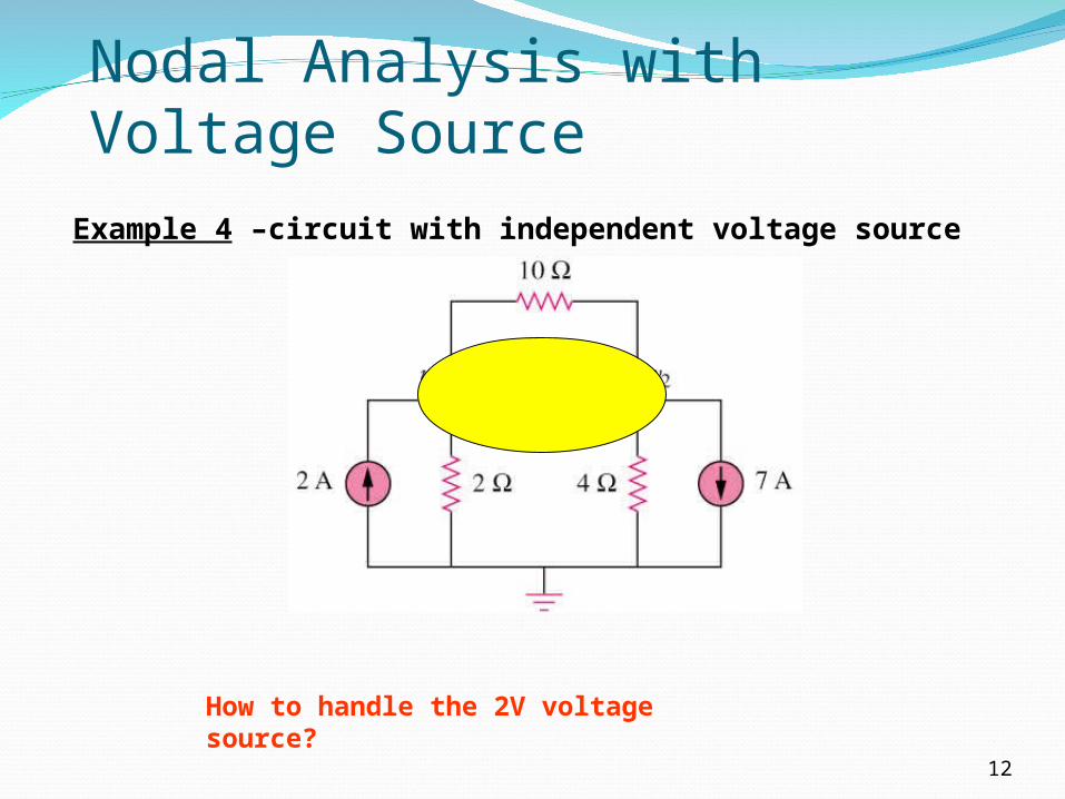
Example 4 –circuit with independent voltage source
How to handle the 2V voltage source?
3.3 Nodal Analysis with Supernode (1)
13
A super-node is formed by enclosing a (dependent or independent) voltage source connected between two non-reference nodes and any elements connected in parallel with it.
*Note: We analyze a circuit with super-nodes using the same three steps mentioned above except that the super-nodes are treated differently.
3.3 Nodal Analysis with supernode (2)
14
Basic steps:
1. Take off all voltage sources in super-nodes and apply KCL to super-nodes.
2. Put voltage sources back to the nodes and apply KVL to relative loops.

3.3 Nodal Analysis with Supernode(3)
15
Example 5 – circuit with independent voltage source
Super-node => 2-i1-i2-7 = 0
Apply KVL => v1+2-v2 = 0
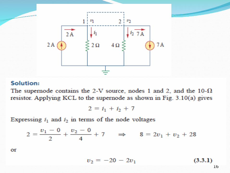
16
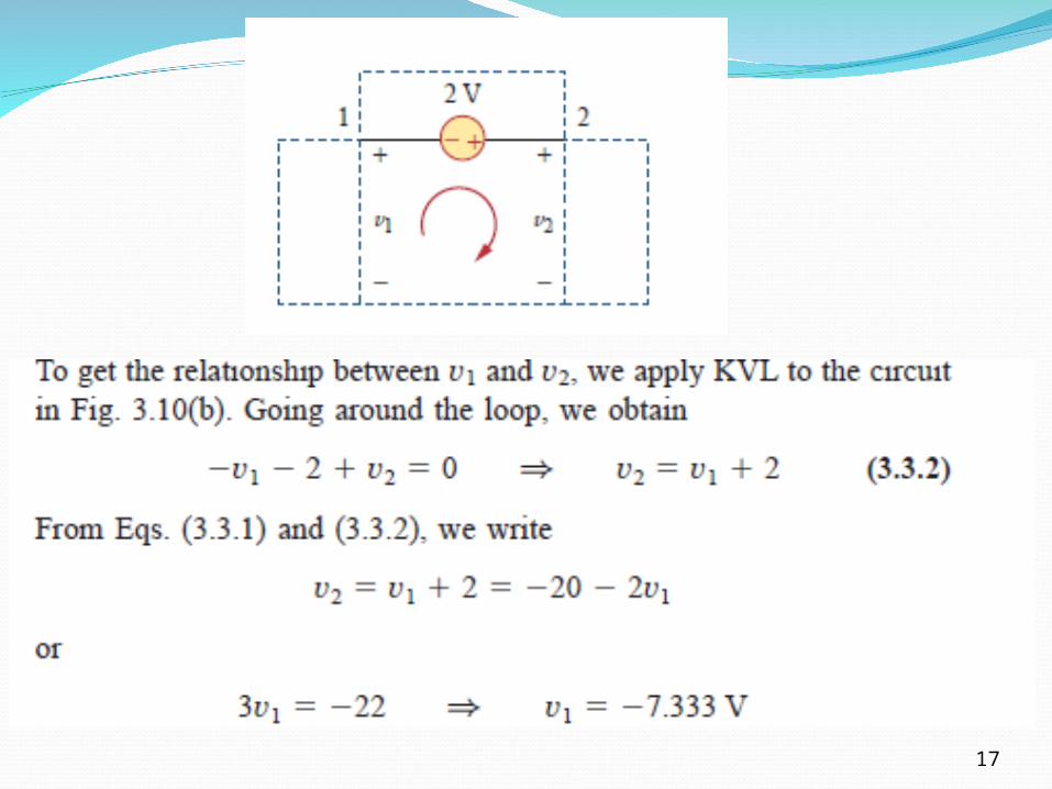
17

3.3 Nodal Analysis with supernode (4)
18
Example 6 – circuit with two independent voltage sources
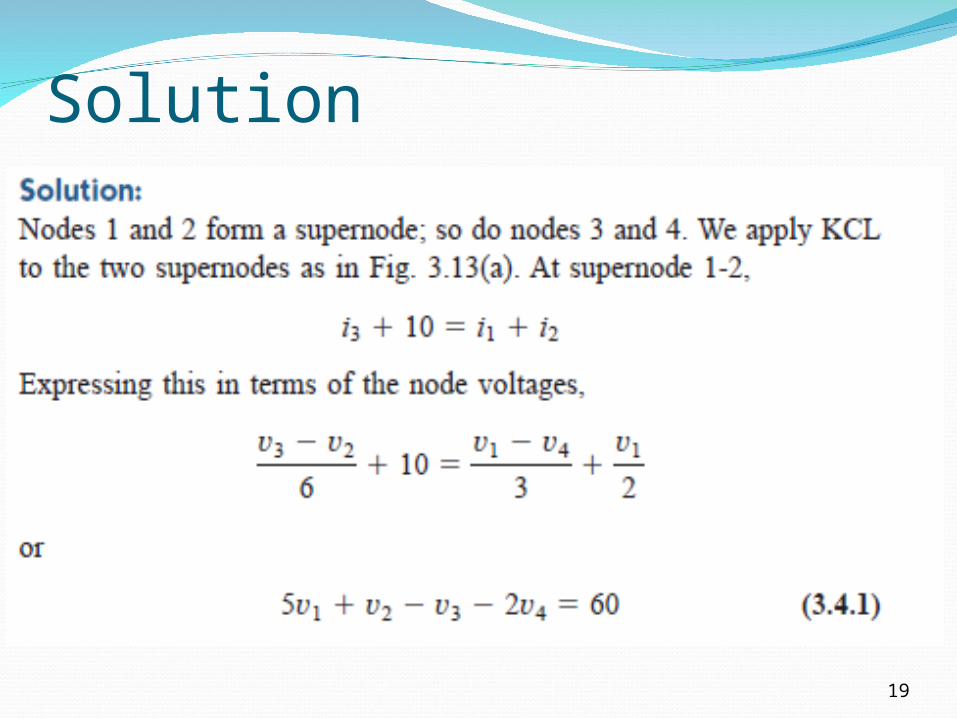
Solution
19
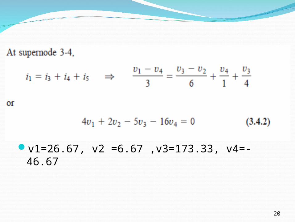
v1=26.67, v2 =6.67 ,v3=173.33, v4=-46.67
20
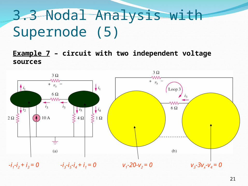
3.3 Nodal Analysis with Supernode (5)
21
Example 7 – circuit with two independent voltage sources
-i1-i2 + i3 = 0 -i3-i5-i4 + i1 = 0 v1-20-v2 = 0 v3-3vx-v4 = 0
3.4 Introduction to Mesh Analysis (1)
22
1. Mesh analysis provides another general procedure for analyzing circuits using mesh currents as the circuit variables.
2. Nodal analysis applies KCL to find unknown voltages in a given circuit, while mesh analysis applies KVL to find unknown currents.
3. A mesh is a loop which does not contain any other loops within it.
3.4 Introduction to Mesh Analysis (2)
23
Steps to determine the mesh currents:
1. Assign mesh currents i1, i2, …, in to the n meshes.
2. Apply KCL to each of the n meshes. Use Ohm’s law to express the voltages in terms of the mesh currents.
3. Solve the resulting n simultaneous equations to get the mesh currents.

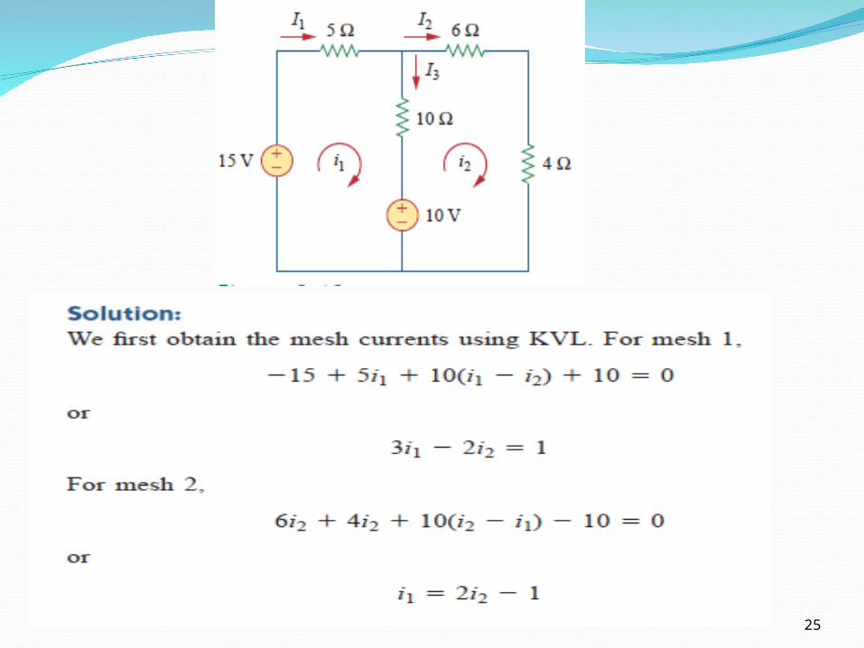
3.4 Introduction to Mesh Analysis (3)
24
Example 8 – circuit with independent voltage sources
*Refer to in-class illustration, textbook
Note:
i1 and i2 are mesh current (imaginative, not measurable directly)
I1, I2 and I3 are branch current (real, measurable directly)
I1 = i1; I2 = i2; I3 = i1 - i2
25

3.4 Mesh Analysis with dependent source
26
Example 9 – circuit with dependent voltage source
*Refer to in-class illustration, textbook, answer Io = 1.5A
3.5 Mesh Analysis with supermesh (1)
27
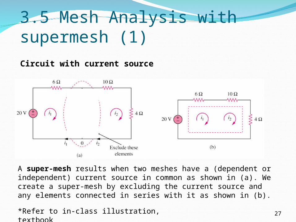
Circuit with current source
*Refer to in-class illustration, textbook
A super-mesh results when two meshes have a (dependent or independent) current source in common as shown in (a). We create a super-mesh by excluding the current source and any elements connected in series with it as shown in (b).
3.5 Mesh Analysis with supermesh (2)
28
The properties of a super-mesh:
1. The current source in the super-mesh is not completely ignored; it provides the constraint equation necessary to solve for the mesh currents.
2. A super-mesh has no current of its own.
3. A super-mesh requires the application of both KVL and KCL.

3.6 Mesh Analysis with supermesh (3)
29
The properties of a super-mesh:
1. The current source in the super-mesh is not completely ignored; it provides the constraint equation necessary to solve for the mesh currents.
2. A super-mesh has no current of its own.
3. A super-mesh requires the application of both KVL and KCL.

Nodal versus Mesh Analysis
30
To select the method that results in the smaller number of equations. For example:
1. Choose nodal analysis for circuit with fewer nodes than meshes.*Choose mesh analysis for circuit with fewer meshes
than nodes.*Networks that contain many series connected
elements, voltage sources, or supermeshes are more suitable for mesh analysis.
*Networks with parallel-connected elements, current sources, or supernodes are more suitable for nodal analysis.
2. If node voltages are required, it may be expedient to apply nodal analysis. If branch or mesh currents are required, it may be better to use mesh analysis.

3.7 Source Transformation (1)
31
• An equivalent circuit is one whose v-i characteristics are identical with the original circuit.
• It is the process of replacing a voltage source vS in series with a resistor R by a current source iS in parallel with a resistor R, or vice versa.

3.7 Source Transformation (2)
32
(a) Independent source transform
(b) Dependent source transform
•The arrow of the current source is
directed toward the positive
terminal of the voltage source.
•The source transformation is not possible when R = 0 for voltage source and R = ∞ for current source.
++
++
--
--
3.7 Source Transformation (3)
33
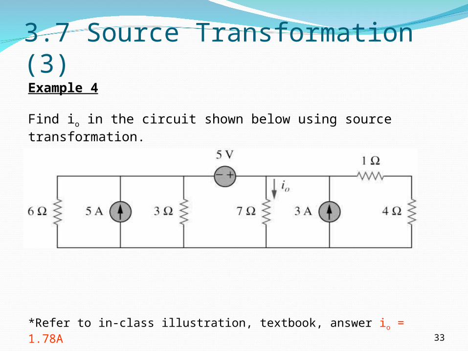
Example 4
Find io in the circuit shown below using source transformation.
*Refer to in-class illustration, textbook, answer io = 1.78A
3.8a Norton’s Theorem (1)
34
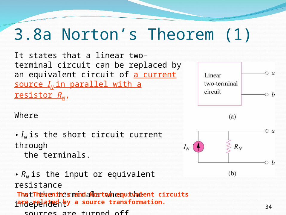
It states that a linear two-terminal circuit can be replaced by an equivalent circuit of a current source IN in parallel with a resistor RN,
Where • IN is the short circuit current through the terminals. • RN is the input or equivalent resistance at the terminals when the independent sources are turned off.
The Thevenin’s and Norton equivalent circuits are related by a source transformation.
3.8a Norton’s Theorem (2)
35
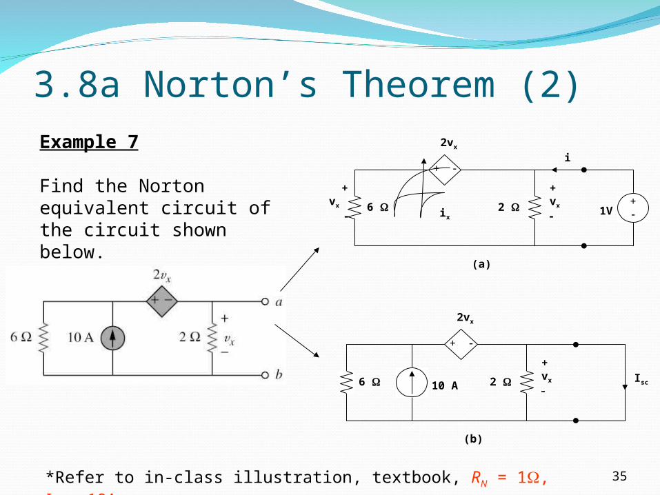
Example 7
Find the Norton equivalent circuit of the circuit shown below.
*Refer to in-class illustration, textbook, RN = 1, IN = 10A.
2
(a)
6
2vx
+
+vx
+vx
1V+ix
i
2
(b)
6 10 A
2vx
+
+vx
Isc

3.8b Thevenin’s Theorem (1)
36
It states that a linear two-terminal circuit (Fig. a) can be replaced by an equivalent circuit (Fig. b) consisting of a voltage source VTH in series with a resistor RTH,
where
• VTH is the open-circuit voltage at the terminals.
• RTH is the input or equivalent resistance at the terminals when the independent sources are turned off.

3.8b Thevenin’s Theorem (2)
37
Example 5
Using Thevenin’s theorem, find the equivalent circuit to the left of the terminals in the circuit shown below. Hence find i.
*Refer to in-class illustration, textbook, answer VTH = 6V, RTH = 3, i = 1.5A
6
4
(a)
RTh
6
2A
6
4
(b)
6 2A
+VTh

3.8b Thevenin’s Theorem (3)
38
Example 6
Find the Thevenin equivalent circuit of the circuit shown below to the left of the terminals.
*Refer to in-class illustration, textbook, answer VTH = 5.33V, RTH = 3
6 V
5 Ix
4 +
(a)
1.5Ix
i1
i2
i1 i2
3
o
+VTh
b
a
1.5Ix 1 V+
3 0.5Ix
5
(b)
a
b
4
Ix i
3.9a Maximum Power Transfer (1)
L
ThTHL R
VPRR
4
2
max
LLTh
ThL R
RR
VRiP
2
2
39
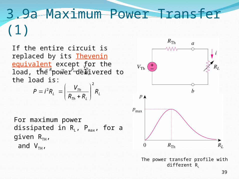
If the entire circuit is replaced by its Thevenin equivalent except for the load, the power delivered to the load is:
The power transfer profile with different RL
For maximum power dissipated in RL, Pmax, for a given RTH, and VTH,

3.9a Maximum Power Transfer (2)
40
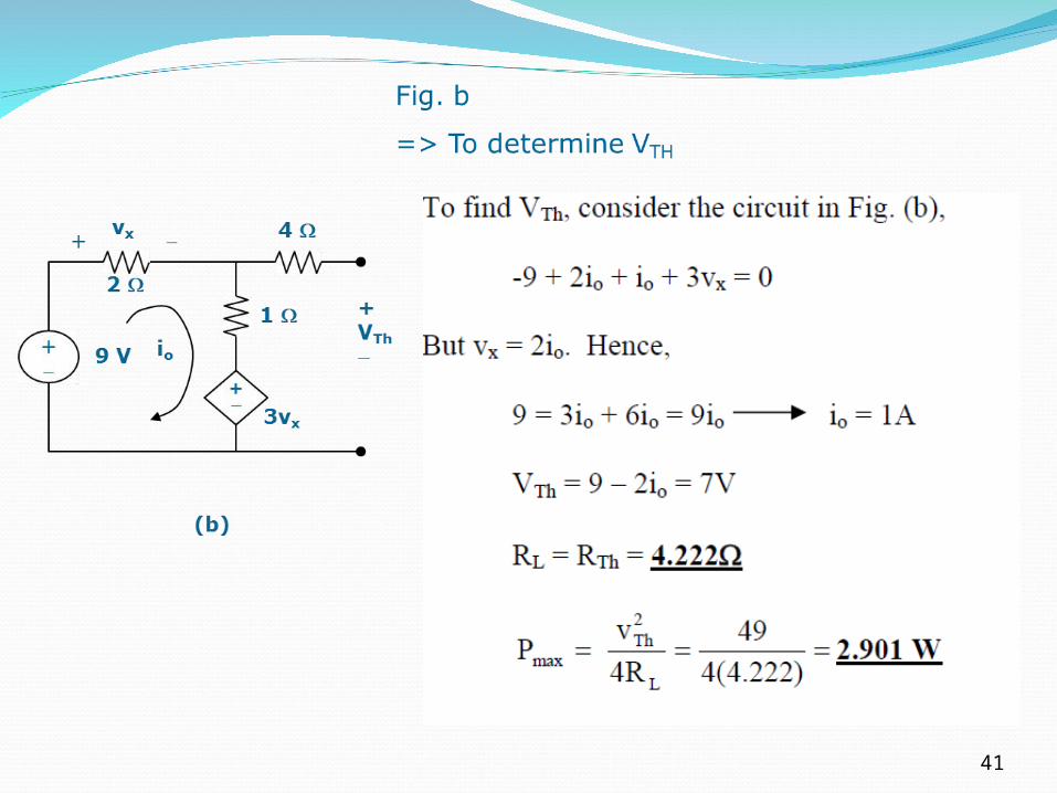
Example 8
Determine the value of RL that will draw the maximum power from the rest of the circuit shown below. Calculate the maximum power.
2
4
1 V+
(a)
1
3vx
+
i
v0+ vx RTH
41
3.9b Superposition Theorem (1)
42
It states that the voltage across (or current through) an element in a linear circuit is the algebraic sum of the voltage across (or currents through) that element due to EACH independent source acting alone.
The principle of superposition helps us to analyze a linear circuit with more than one independent source by calculating the contribution of each independent source separately.

3.9b Superposition Theorem (2)
43
We consider the effects of 8A and 20V one by one, then add the two effects together for final vo.
3.9b Superposition Theorem (3)
44
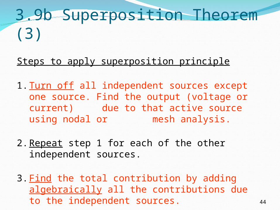
Steps to apply superposition principle
1. Turn off all independent sources except one source. Find the output (voltage or current) due to that active source using nodal or mesh analysis.
2. Repeat step 1 for each of the other independent sources.
3. Find the total contribution by adding algebraically all the contributions due to the independent sources.

3.9b Superposition Theorem (4)
45
Two things have to be keep in mind:
1. When we say turn off all other independent sources: Independent voltage sources are replaced
by 0 V (short circuit) and Independent current sources are replaced
by 0 A (open circuit).
2. Dependent sources are left intact because they are controlled by circuit variables.
3.9b Superposition Theorem (5)
46
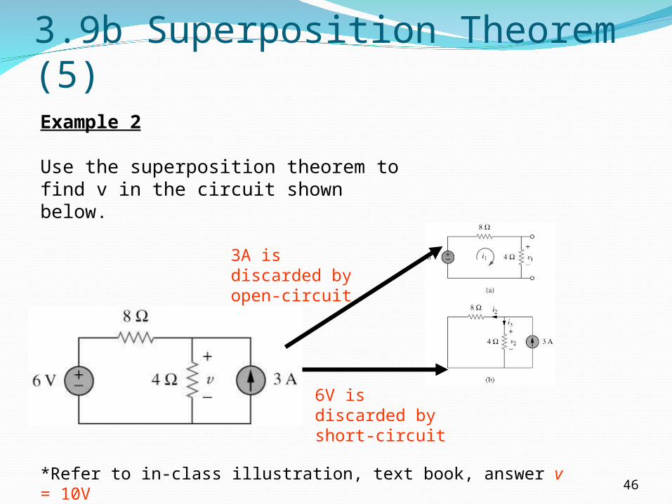
Example 2
Use the superposition theorem to find v in the circuit shown below.
3A is discarded by open-circuit
6V is discarded by short-circuit
*Refer to in-class illustration, text book, answer v = 10V

3.9b Superposition Theorem (6)
47
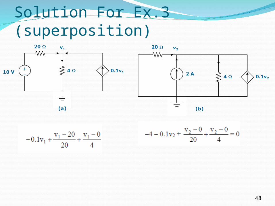
Example 3
Use superposition to find vx in the circuit below.
*Refer to in-class illustration, text book, answer Vx = 12.5V
2A is discarded by open-circuit
20 v1
4 10 V+
(a)
0.1v14
2 A
(b)
20
0.1v2
v2
10V is discarded by open-circuit
Dependant source keep unchanged
Solution For Ex.3 (superposition)
48