CHAPTER 3 CHECKOUT, CALIBRATION AND MAINTENANCE …€¦ · · 2005-08-19CHAPTER 3 CHECKOUT,...
46
Page 3-1 CHAPTER 3 CHECKOUT, CALIBRATION AND MAINTENANCE Effective 08/2005 CHAPTER 3 CHECKOUT, CALIBRATION AND MAINTENANCE GENERAL An efficient and proper troubleshooting method of repair is to analyze the logical order of events. Recogni- tion of symptoms which naturally occur in a certain sequence (depending on failure) will aid in the quick location of system errors. This method of logical deduction has been used for years by the most successful technicians. During the power up sequence the aligner is first a computer, the software load transforms the machine into an alignment instrument. Even as an aligner, things must execute in a certain fashion. When this order is known we can determine the system malfunction easily by observing the symptoms. The following checks (in order) will aid in determining which section of the aligner a failure occurs. UNIT CHECKOUT PROCEDURE ALL VERSIONS 1. Check for 115VAC power at the wall outlet and at the terminal strip inside the back door assembly. 2. Power on check, listen for fail code beeps, system messages the unit should begin the boot up process and load the alignment software. NOTE: THE ROM BIOS ALSO CONTAINS A SIMPLE SYSTEM CHECK PROGRAM WHICH EXECUTES JUST AFTER TURN-ON. DOS/WINDOWS DIAGNOSTICS SOFTWARE. THIS IS A VERY GOOD AS WELL AS THOROUGH MICROPROCESSOR DIAGNOSTIC TOOL. 3. Check 115VAC power at the Power Supply PCB inside the USB HIB Box P1 pins 1 and 2. 4. Check 10VDC power at the Power Supply PCB P2 pins 1, 2 and 3. 5. Aligner software download. Check to make sure that the alignment software loads both the HIB USB support and the alignment database. 6. Communications..Assuming all console display functions are OK, go to the Maintenance - Measure- ments Data - Raw Values Only screen. Monitor the activity of the heads by plugging 1 sensor at a time into the interconnect PCB on the back of the console. If the unit fails to report a wheel sensor try an- other receptacle on the back of the unit each run in parallel and will accept any sensor. If the unit still fails to report the wheel sensor try a different cable. 7. Continue to plug in all 4 wheel sensors until communication has been established with each one. 8. Set the calibration hardware up on the front of the alignment rack with the numbers on the bar on the left side of the rack. 9. Valid camber. With the heads on the calibration bar, check for valid camber. With the sensors mounted on the calibration bar the camber output on the Raw Values only screen should not exceed ± 1.50 degrees. 10. Move one end of the calibration bar to the lower cutout on the calibration stands. Verify that the camber reading changes 4 degrees in the direction of camber change. Repeat this step with the opposite side. 11. Valid SAI. With the heads on the calibration bar, check for valid SAI. With the sensors mounted and leveled on the calibration bar the SAI output on the Raw Values only screen should not exceed ±3.00 degrees. Tilting the wheel sensor up should make the values go negative and tilting it down should make the values go positive. 11. Valid CrossToe. Again with both front sensors mounted on the calibration bar check for a good cross toe reading. Using the raw values only screen, and a level bar. The raw value should not exceed ± 2.00 degrees. 12. Valid Track Toe. Remove each wheel sensor from the calibration bar and mount the sensors on the bar 90 degrees from the original location. The raw value should not exceed ± 1.50 degrees. 13. Mechanical - Wheel clamps and turntables. Check for variances in camber readings as the clamps are rotated. Note any camber change. Using the same wheel sensor mount a different wheel clamp to the same tire and wheel in the same location and rotate the assembly 360 degrees and note any camber change. Complete this procedure with all 4 wheel clamps using the process of elimination.
Transcript of CHAPTER 3 CHECKOUT, CALIBRATION AND MAINTENANCE …€¦ · · 2005-08-19CHAPTER 3 CHECKOUT,...

Page 3-1
CHAPTER 3 CHECKOUT, CALIBRATION AND MAINTENANCE
Effective08/2005
CHAPTER 3CHECKOUT, CALIBRATION AND MAINTENANCE
GENERALAn efficient and proper troubleshooting method of repair is to analyze the logical order of events. Recogni-tion of symptoms which naturally occur in a certain sequence (depending on failure) will aid in the quicklocation of system errors. This method of logical deduction has been used for years by the most successfultechnicians.During the power up sequence the aligner is first a computer, the software load transforms the machine intoan alignment instrument. Even as an aligner, things must execute in a certain fashion. When this order isknown we can determine the system malfunction easily by observing the symptoms.
The following checks (in order) will aid in determining which section of the aligner a failure occurs.
UNIT CHECKOUT PROCEDURE ALL VERSIONS
1. Check for 115VAC power at the wall outlet and at the terminal strip inside the back door assembly.2. Power on check, listen for fail code beeps, system messages the unit should begin the boot up process
and load the alignment software.
NOTE: THE ROM BIOS ALSO CONTAINS A SIMPLE SYSTEM CHECK PROGRAM WHICH EXECUTESJUST AFTER TURN-ON. DOS/WINDOWS DIAGNOSTICS SOFTWARE. THIS IS A VERY GOODAS WELL AS THOROUGH MICROPROCESSOR DIAGNOSTIC TOOL.
3. Check 115VAC power at the Power Supply PCB inside the USB HIB Box P1 pins 1 and 2.4. Check 10VDC power at the Power Supply PCB P2 pins 1, 2 and 3.5. Aligner software download. Check to make sure that the alignment software loads both the HIB USB
support and the alignment database.6. Communications..Assuming all console display functions are OK, go to the Maintenance - Measure-
ments Data - Raw Values Only screen. Monitor the activity of the heads by plugging 1 sensor at a timeinto the interconnect PCB on the back of the console. If the unit fails to report a wheel sensor try an-other receptacle on the back of the unit each run in parallel and will accept any sensor. If the unit stillfails to report the wheel sensor try a different cable.
7. Continue to plug in all 4 wheel sensors until communication has been established with each one.8. Set the calibration hardware up on the front of the alignment rack with the numbers on the bar on the left
side of the rack.9. Valid camber. With the heads on the calibration bar, check for valid camber. With the sensors mounted
on the calibration bar the camber output on the Raw Values only screen should not exceed ± 1.50degrees.
10. Move one end of the calibration bar to the lower cutout on the calibration stands. Verify that the camberreading changes 4 degrees in the direction of camber change. Repeat this step with the opposite side.
11. Valid SAI. With the heads on the calibration bar, check for valid SAI. With the sensors mounted andleveled on the calibration bar the SAI output on the Raw Values only screen should not exceed ±3.00degrees. Tilting the wheel sensor up should make the values go negative and tilting it down shouldmake the values go positive.
11. Valid CrossToe. Again with both front sensors mounted on the calibration bar check for a good cross toereading. Using the raw values only screen, and a level bar. The raw value should not exceed ± 2.00degrees.
12. Valid Track Toe. Remove each wheel sensor from the calibration bar and mount the sensors on the bar90 degrees from the original location. The raw value should not exceed ± 1.50 degrees.
13. Mechanical - Wheel clamps and turntables. Check for variances in camber readings as the clamps arerotated. Note any camber change. Using the same wheel sensor mount a different wheel clamp to thesame tire and wheel in the same location and rotate the assembly 360 degrees and note any camberchange. Complete this procedure with all 4 wheel clamps using the process of elimination.

Page 3-2
CHAPTER 3CHECKOUT, CALIBRATION AND MAINTENANCE
Effective08/2005
ALIGNMENT SOFTWARE INSTALLATION
1. Software Components required:• Alignment Software CD• Brand “Key Disk” floppy• Platinum Options “Key Disk” floppy• Specification CD• Specification “Key Disk” floppy
2. Boot the aligner to the Windows desktop.(Figure 3-1)
3. Insert the CD labeled Alignment software. If“Auto insert” is turned on the alignment softwarewill automatically begin the installation process.
4. The install program will first install the EZ Shimsoftware. After EZ Shim has been installed theunit will automatically re-boot.
5. After re-booting the unit will install Acrobat®Reader. After Acrobat® has been loaded theunit will once again re-boot. (Figure 3-2)
NOTE: IF THE UNIT DOES NOT RE-BOOTAFTER THE INSTALLATION OFACROBAT®, THE UNIT WILL NEED TOBE RESTARTED BY RE-INSERTING THEALIGNMENT PROGRAM BACK INTO THECD DRIVE.
6. After rebooting, the alignment program will runand begin to load the alignment software. Theinstall Wizard is the first screen to appear. Press<NEXT> to begin the installation. (Figure 3-3)
Figure 3-1
Figure 3-2
Figure 3-3
Page 3-3
CHAPTER 3 CHECKOUT, CALIBRATION AND MAINTENANCE
Effective08/2005
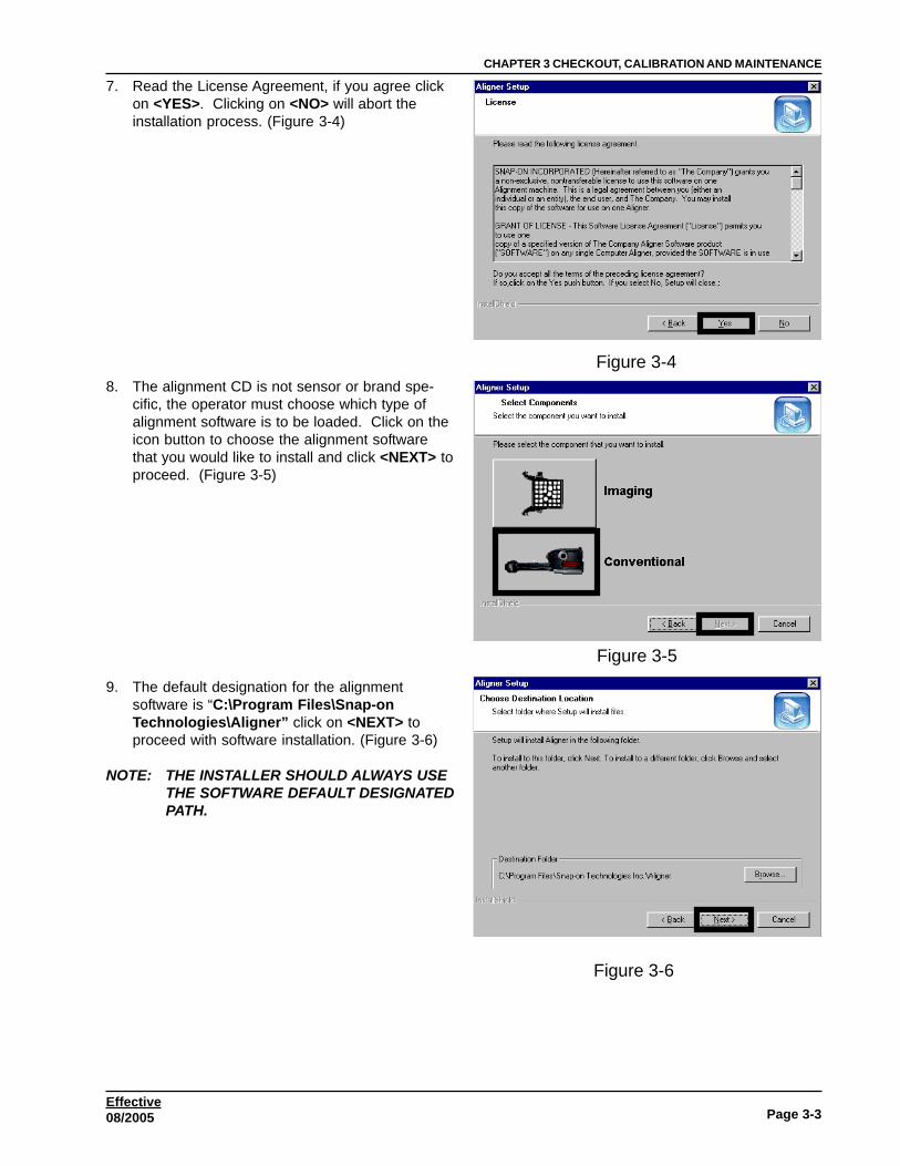
7. Read the License Agreement, if you agree clickon <YES>. Clicking on <NO> will abort theinstallation process. (Figure 3-4)
8. The alignment CD is not sensor or brand spe-cific, the operator must choose which type ofalignment software is to be loaded. Click on theicon button to choose the alignment softwarethat you would like to install and click <NEXT> toproceed. (Figure 3-5)
9. The default designation for the alignmentsoftware is “C:\Program Files\Snap-onTechnologies\Aligner” click on <NEXT> toproceed with software installation. (Figure 3-6)
NOTE: THE INSTALLER SHOULD ALWAYS USETHE SOFTWARE DEFAULT DESIGNATEDPATH.
Figure 3-4
Figure 3-5
Figure 3-6

Page 3-4
CHAPTER 3CHECKOUT, CALIBRATION AND MAINTENANCE
Effective08/2005
10. The next screen to appear is the languageselection screen. The aligner has manydifferent languages for easy user interface.Select the languages for this installation andthen click <NEXT>. (Figure 3-7)
11. The aligner confirms the languages that havebeen chosen. Click on <NEXT> to proceedwith the installation. If a language is notchosen, the operator can click on <BACK> tostep back a screen the select additionallanguages. (Figure 3-8)
NOTE: AFTER INSTALLATION A USER CANADD ADDITIONAL LANGUAGES ATANY TIME BY RE-INSTALLING THESOFTWARE. THIS PROCESS WILLNOT OVERWRITE ANY PREFERENCESALREADY SETUP BY OTHER USERS IFTHE DEFAULT DESIGNATION WASCHOSEN IN STEP 9.
12. After a successful installation the Install ShieldWizard will display a installation complete. Theunit will need to be re-booted before you canuse the program, click on <FINISH> to re-bootthe aligner. (Figure 3-9)
Figure 3-7
Figure 3-8
Figure 3-9
Page 3-5
CHAPTER 3 CHECKOUT, CALIBRATION AND MAINTENANCE
Effective08/2005
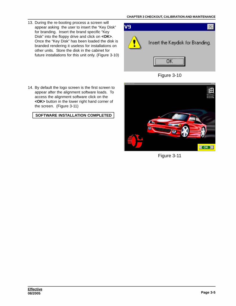
13. During the re-booting process a screen willappear asking the user to insert the “Key Disk”for branding. Insert the brand specific “KeyDisk” into the floppy drive and click on <OK>.Once the “Key Disk” has been loaded the disk isbranded rendering it useless for installations onother units. Store the disk in the cabinet forfuture installations for this unit only. (Figure 3-10)
14. By default the logo screen is the first screen toappear after the alignment software loads. Toaccess the alignment software click on the<OK> button in the lower right hand corner ofthe screen. (Figure 3-11)
SOFTWARE INSTALLATION COMPLETED
Figure 3-10
Figure 3-11
Page 3-6
CHAPTER 3CHECKOUT, CALIBRATION AND MAINTENANCE
Effective08/2005
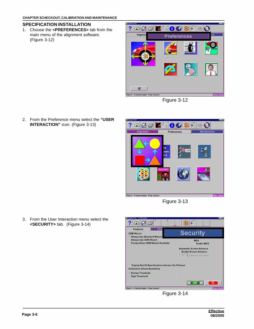
SPECIFICATION INSTALLATION1. Choose the <PREFERENCES> tab from the
main menu of the alignment software.(Figure 3-12)
2. From the Preference menu select the “USERINTERACTION” icon. (Figure 3-13)
3. From the User Interaction menu select the<SECURITY> tab. (Figure 3-14)
Figure 3-12
Figure 3-13
Figure 3-14

Page 3-7
CHAPTER 3 CHECKOUT, CALIBRATION AND MAINTENANCE
Effective08/2005
4. From the Security Menu select the “KEY DISK”radio button. Insert the “SPECIFICATION KEYDISK” into the floppy drive and select <APPLY>.Once the “Key Disk” has been loaded the disk isbranded rendering it useless for installations onother units. Store the disk in the cabinet forfuture installations for this unit only. (Figure 3-15)
5. Jump back to the Main Alignment menu byclicking on the “HOME” key in the upper lefthand corner. (Figure 3-16)
6. Choose the <Maintenance> tab from the MainMenu. (Figure 3-17)
Figure 3-15
Figure 3-16
Figure 3-17

Page 3-8
CHAPTER 3CHECKOUT, CALIBRATION AND MAINTENANCE
Effective08/2005
7. Choose the “Windows Utilities” icon from theMaintenance Menu. (Figure 3-18)
8. Double click on the “Install” icon from the Win-dows Utilities. (Figure 3-19)
9. Insert the specification CD in the DVD drive andchoose the “Install from CD” radio button andclick on <OK>. (Figure 3-20)
Figure 3-18
Figure 3-19
Figure 3-20

Page 3-9
CHAPTER 3 CHECKOUT, CALIBRATION AND MAINTENANCE
Effective08/2005
10. Choose the language for installation. This doesnot choose a particular specification database.This language selection onlly changes thedialogue for the installation of the software.(Figure 3-20.1)
11. Follow all on screen instructions using thedefault directory for installation. When promptedre-boot the aligner. (Figure 3-21)
SPECIFICATION INSTALLATION COMPLETED
Figure 3-20.1
Figure 3-21

Page 3-10
CHAPTER 3CHECKOUT, CALIBRATION AND MAINTENANCE
Effective08/2005
PLATINUM SOFTWARE INSTALLATION
1. Choose the <PREFERENCES> tab from themain menu of the alignment software.(Figure 3-22)
2. From the Preference menu select the “USERINTERACTION” icon. (Figure 3-23)
3. From the User Interaction menu select the<SECURITY> tab. (Figure 3-24)
Figure 3-22
Figure 3-23
Figure 3-24

Page 3-11
CHAPTER 3 CHECKOUT, CALIBRATION AND MAINTENANCE
Effective08/2005
4. From the Security Menu select the “KEY DISK”radio button. Insert the “PLATINUM KEY DISK”into the floppy drive and select <APPLY>. Oncethe “Key Disk” has been loaded the disk isbranded rendering it useless for installations onother units. Store the disk in the cabinet forfuture installations for this unit only. (Figure 3-25)
PLATINUM INSTALLATION COMPLETED
Figure 3-25

Page 3-12
CHAPTER 3CHECKOUT, CALIBRATION AND MAINTENANCE
Effective08/2005
MAINTENANCE MENUThis screen is the hub of all Pro32™ service andmaintenance. (Figure 3-26) Icon selections are:
Calibration – the software thatenables the measuring heads to becalibrated using the optional Cus-tomer Calibration Kit
Measurement Data – primarily forservice personnel, this allowsaccess to measuring sensor directoutput.
Preventative Maintenance – a software feature that guides the equipment operatorthrough recommended periodic aligner maintenance.
Demo Mode - A program used primarily by sales representatives and training personnel.This is program that demonstrates the capabilities of the aligner software without actuallyhaving measuring heads or a vehicle available. It is a useful tool for training new orexperienced users about machine features.
Windows Utilities – Allows access to the Windows Desktop and also allows the operator toperform routine installation of printers, software, etc.
Database Utilities – The feature is used for backing up and restoring alignment based datafiles, customer data, etc.
Speaker Training – Optional Hardware / Software package that allows and end-user tocontrol the aligner through voice commands.
Figure 3-26
Page 3-13
CHAPTER 3 CHECKOUT, CALIBRATION AND MAINTENANCE
Effective08/2005
CALIBRATION MENU
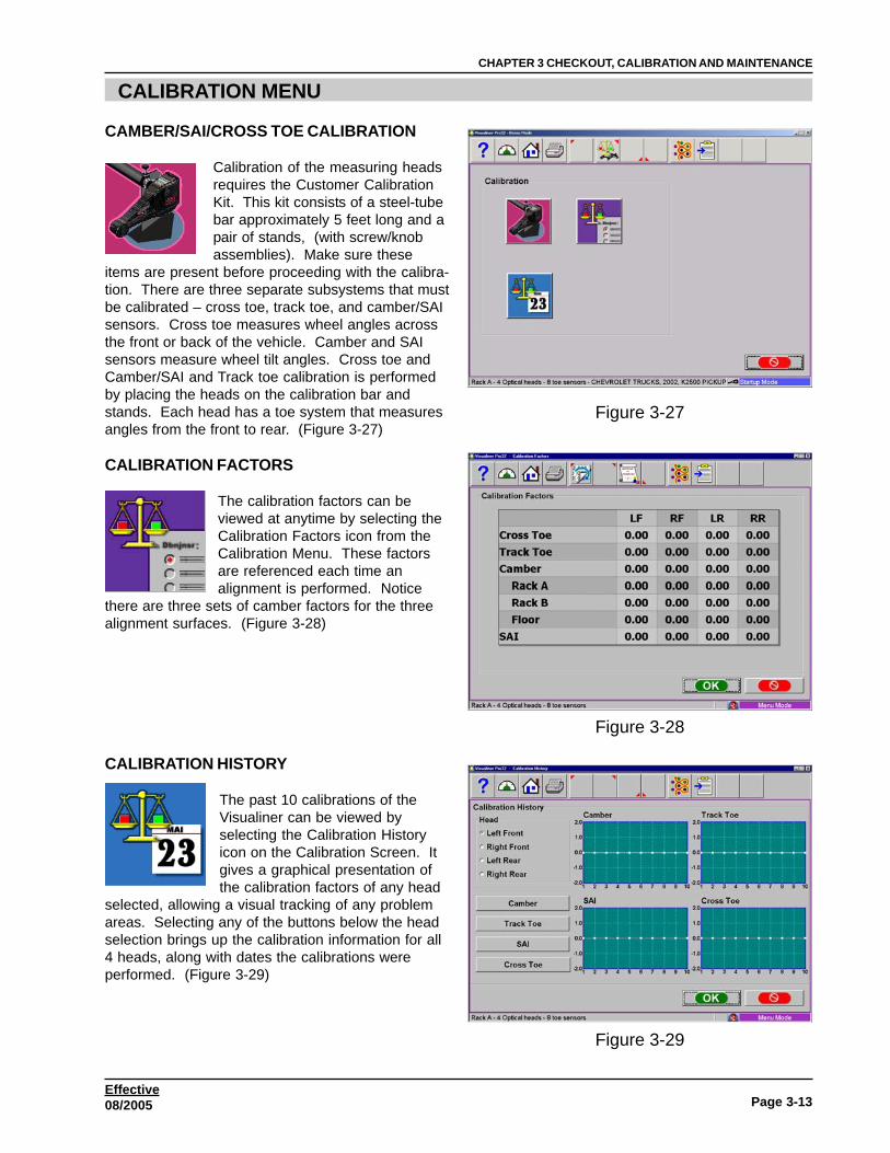
CAMBER/SAI/CROSS TOE CALIBRATION
Calibration of the measuring headsrequires the Customer CalibrationKit. This kit consists of a steel-tubebar approximately 5 feet long and apair of stands, (with screw/knobassemblies). Make sure these
items are present before proceeding with the calibra-tion. There are three separate subsystems that mustbe calibrated – cross toe, track toe, and camber/SAIsensors. Cross toe measures wheel angles acrossthe front or back of the vehicle. Camber and SAIsensors measure wheel tilt angles. Cross toe andCamber/SAI and Track toe calibration is performedby placing the heads on the calibration bar andstands. Each head has a toe system that measuresangles from the front to rear. (Figure 3-27)
CALIBRATION FACTORS
The calibration factors can beviewed at anytime by selecting theCalibration Factors icon from theCalibration Menu. These factorsare referenced each time analignment is performed. Notice
there are three sets of camber factors for the threealignment surfaces. (Figure 3-28)
CALIBRATION HISTORY
The past 10 calibrations of theVisualiner can be viewed byselecting the Calibration Historyicon on the Calibration Screen. Itgives a graphical presentation ofthe calibration factors of any head
selected, allowing a visual tracking of any problemareas. Selecting any of the buttons below the headselection brings up the calibration information for all4 heads, along with dates the calibrations wereperformed. (Figure 3-29)
Figure 3-27
Figure 3-28
Figure 3-29

Page 3-14
CHAPTER 3CHECKOUT, CALIBRATION AND MAINTENANCE
Effective08/2005
CAMBER, SAI, CROSS TOE AND TRACK TOE CALIBRATION PROCEDURES
NOTE: FOLLOW ALL ON-SCREEN INSTRUC-TIONS CAREFULLY TO ENSURE QUAL-ITY RESULTS.
1. Click on the Camber/SAICalibration icon on the Calibrationscreen. The first screen to appearis shown in (Figure 3-30)
2. Select whether the front or rear sensors are tobe calibrated by clicking on the proper radiobutton.
3. Choose the rack that the calibration is to beperformed on. Up to 3 alignment surfaces canbe utilized, and each must be calibrated inde-pendently. In most shops, Rack A is the primaryalignment surface – choices are Rack A, Rack B,or Floor.
4. Set the calibration stands on the front (turnplates) with the open end of the stands facingthe rear of the alignment lift. Set the calibrationbar into the notched sections of the stands withthe numbers that are printed on the bar on theleft hand side. Click on the “OK” button in thelower right hand corner.
NEXT STEP
1. Rotate the bar forward until the #4 is at 12:00.
2. Slide both the left and right front sensors into thecalibration bar with the groove on the stub shaftfacing up.
3. Hand tighten the left and right thumb screws onthe calibration bar.
4. Rotate the bar forward until the #1 is at the 12:00position.
5. Level and lock both sensors using the level vialthat is mounted on the outside shell of thesensor. This procedure automatically sets theelectronic level inside the sensor.
6. Gently press the “runout” key on one of thefront sensors.
Figure 3-30

Page 3-15
CHAPTER 3 CHECKOUT, CALIBRATION AND MAINTENANCE
Effective08/2005
NEXT STEP1. Un-lock both the left and right sensors by turning
the knob counter clockwise.
2. Rotate the bar forward until the #2 is at 12:00.
3. Using the electronic level on the keypad, levelboth the left and right sensors and lock themusing the sensor locking knob.
NOTE: IF A HEAD IS NOT LEVEL DURING THISSTEP A MESSAGE IS DISPLAYED ONSCREEN INDICATING TO LEVEL THEHEADS.
4. Gently press the runout button.
NEXT STEP
1. Un-lock both the left and right sensors by turningthe knob (counter clockwise).
2. Rotate the bar forward until the #3 is at 12:00.
3. Using the electronic level on the keypad, levelboth the left and right sensors and lock themusing the sensor locking knob.
4. Gently press the runout button.
NEXT STEP
1. Un-lock both the left and right sensors by turningthe knob counter clockwise. Rotate the barbackwards to position number “4”.
2. Lock the calibration bar by tightening the handscrew on the calibration stands.
3. Using the electronic level on the keypad, levelboth the left and right sensors and lock themusing the sensor locking knob.
4. Gently press the runout button.
NEXT STEP

Page 3-16
CHAPTER 3CHECKOUT, CALIBRATION AND MAINTENANCE
Effective08/2005
1. Swap the entire assembly from left to right sothat the left sensor is on the RH side facingrearward and the right sensor is on the LH sidefacing rearward. The calibration bar must alsobe rotated so that the numbers are on the RHside of the alignment lift.
2. Rotate the calibration bar so that the number “4”is in the 12:00 position.
3. Using the electronic level on the keypad, levelboth the left and right sensors and lock themusing the sensor locking knob.
4. Gently press the runout button.
NEXT STEP
1. Remove the wheel sensors from the bar andorient them so that both rear toe sensors arefacing each other.
2. Using the electronic level on the keypad, levelboth the left and right sensors and lock themusing the sensor locking knob.
3. Gently press the runout button.
NEXT STEP
After the calibration a screen will appear displayingthe calibration factors of all systems within the frontsensors. The screen has three columns of numbers. The first column“New” displays the calibration factors that were just obtained. Thesecond column “Current” displays the calibration factors that wereobtained from the previously performed calibration. The last column“Change” shows the total amount of change between the two calibra-tions. Should a factor exceed the usable limit, a warning will be dis-played which indicates a possible problem and will recommend that aservice technician be called. Clicking on the “Cancel” button will rejectthe new calibration factors and return to the Calibration Screen.Clicking on the “OK” button will accept the new factors and use them toperform alignments. A fourth column called “Comments” allows the operator to enter any notes aboutwhy the calibration was performed.
Repeat the calibration process for the rear sensors by choosing “Rear Heads” from the calibrationmenu. The rear wheel sensors must be mounted at the rear of the alignment rack for this process.
CALIBRATION COMPLETE

Page 3-17
CHAPTER 3 CHECKOUT, CALIBRATION AND MAINTENANCE
Effective08/2005
CALIBRATION AND PREFERENCE BACKUP
This feature is only available on software revision 3.4 orgreater. All alignment machines are unique in their ownway. Each aligner has different calibration factors andpreferences. CCP alignment softwarealso offers users many different options inthe way of looks and feel. Each userspends many hours customizing thealignment software for his/her look andfeel. Each alignment shop may have adifferent logo that may show up on a printout of eachprinted alignment result. Calibration and Preferencebackup offers the user or technician a way of backing up allcustomized options and alignment calibration to a 1.44mbfloppy diskette. Should an alignment machine require ahard drive replacement the user or technician can simplyrestore all data from a saved floppy diskette back on to thenewly installed hard drive. From the Main Menu click onthe Maintenance Tab click on the Calibration icon andthen click on the Calibration Utilities icon on the toolbar asillustrated above.
Backup - It is recommended after everycalibration that the user backup the newdata in case of a PC or Hard Drive failure.This enables the user to quickly restorethe alignment system’s calibration andpreference data after the operatingsystem has been restored. It is recom-mended that each time the system isbacked up that the same disk be usedand dated on the floppy disk label. A1.44mb formatted floppy diskette isrequired to perform this operation. If thefloppy diskette being used contains anyinformation the system will automaticallyprompt the user to format the disketteusing the operating systems formatcommand.
Restore - Should a hard drive failureoccur, simply install the last knownalignment calibration and preference datadisk and restore the aligner back to theuser’s prefered preference.
NOTE: IF THE OPERATOR IS NOT SURE IF THE SAVED DATA ON THE FLOPPYDISKETTE IS NOT CURRENT IT IS RECOMMENDED THAT A CALIBRATION BEPERFORMED. FAILURE TO HAVE ACCURATE CALIBRATION DATA CAN AND WILLCAUSE EXCESSIVE TIRE WEAR.

Page 3-18
CHAPTER 3CHECKOUT, CALIBRATION AND MAINTENANCE
Effective08/2005
CALIBRATION FACTORS
The chart below lists the calibration limits of the aligner. It is possible for an aligner toexceed the limits and process a good alignment however the range at which the compo-nent inside the wheel sensor will greatly be reduced until the component has been re-placed and re-calibrated.
LF RF LR RR
Cross Toe 0 ± 2.00 0 ± 2.00 0 ± 2.00 0 ± 2.00
Track Toe 0 ± 2.00 0 ± 2.00 0 ± 2.00 0 ± 2.00
Camber 0 ± 3.00 0 ± 3.00 0 ± 3.00 0 ± 3.00
Rack A 0 ± 1.50 0 ± 1.50 0 ± 1.50 0 ± 1.50
Rack B 0 ± 1.50 0 ± 1.50 0 ± 1.50 0 ± 1.50
Floor 0 ± 1.50 0 ± 1.50 0 ± 1.50 0 ± 1.50
SAI 0 ± 3.00 0 ± 3.00 0 ± 3.00 0 ± 3.00
CALIBRATION FACTORS EXCEED LIMITS
During normal use of the aligner it is possible thatcomponents inside the wheel sensors become un-stable and no longer able to hold a tolerance.During the calibration procedure the operator canreceive a return error indicating that a problem exist.The operator should first determine the severity ofthe error. Most errors that arise during calibrationare normally operator errors and can be easilycorrected by recalibrating the wheel sensors. How-ever if after a re-calibration the error still exists, theoperator will receive the returned error (Figure 3-31)
After clicking on the <OK> button, the next screenindicates which component has exceeded the limitsand signals the operator to call customer service todetermine the error. (Figure 3-32) The red boxaround the data indicates which component is out oftolerance. There are NO ADJUSTMENTS that canbe made inside the wheel sensor to correct suchproblems and will require that a component bechanged to correct the problem. The illustration tothe right indicates that a Camber Tilt Sensor hasexceeded the limits and will require replacement.After replacing the “Tilt Sensor” a calibration will berequired to bring the unit back to Factory Specifica-tions.
Figure 3-31
Figure 3-32

Page 3-19
CHAPTER 3 CHECKOUT, CALIBRATION AND MAINTENANCE
Effective08/2005
CALIBRATION CHANGE
The aligner has a built in safety net to alert theoperator of an exceeded amount of change. Thealigner looks at the calibration factors that are storedinto the unit and compares them with the new factorsthat were generated from the completed calibration.Should this amount of change exceed the limits theoperator is alerted with a “red” box around the data.The illustration (Figure 3-33) indicates which compo-nent inside the wheel sensor has the exceededchange. This change does not indicate a problemwith the unit, it alerts the operator that an exceededchange has taken place. If the operator is sure thatthe calibration was performed correctly click on<OK> to accept the new factors. These new factorswill replace the current factors. If the problem ispersistent to a particular wheel sensor and compo-nent, it may indicate that a component inside thewheel sensor is un-stable. Replace the defectivecomponent and re-calibrate.
Should a component execeed it’s limit the operator will receive an “Exceeded Change” message. Thischange looks at the “Current Factor” and compares it to the “New Factor”. Refer to the chart below for theamount of change needed to flag an operator during calibration.
LF RF LR RR
Cross Toe ± .25 ± .25 ± .25 ± .25
Track Toe ± .25 ± .25 ± .25 ± .25
Camber ± .25 ± .25 ± .25 ± .25
Rack A ± .25 ± .25 ± .25 ± .25
Rack B ± .25 ± .25 ± .25 ± .25
Floor ± .25 ± .25 ± .25 ± .25
SAI ± 1.00 ± 1.00 ± 1.00 ± 1.00
Figure 3-33

Page 3-20
CHAPTER 3CHECKOUT, CALIBRATION AND MAINTENANCE
Effective08/2005
Wheel Sensor dropped SAI change
CALIBRATION HISTORY
The calibration history displays thelast 10 calibrations performed onthe aligner. The chart is graphed,the X factor is numbered 1 thru 10(last 10 calibrations) 1 being thecalibration just performed and theY factor is numbered -2.0 thru+2.0 (Raw Data).
By selecting the radio button under the “Head” theunit will return a graph for that Wheel Sensor anddisplay the last 10 calibrations for each componentinside the wheel sensor. (Figure 3-34) The operatoralso may view any notes that may have beenentered by selecting the buttons in the lower half ofthe screen. Each time a calibration is performed the10th calibration history and notes are purged and thehistory is moved 1 becomes 2 and 2 becomes 3 andso on up through 10.
Example(Figure 3-35) displays the Calibration Notes for theLF SAI Wheel Sensor. By selecting the “SAI” buttonthe operator can view any notes that may have beenadded for that particular calibration. The operatorcan choose either Camber, Track Toe, SAI andCross Toe
Figure 3-34
Figure 3-35

Page 3-21
CHAPTER 3 CHECKOUT, CALIBRATION AND MAINTENANCE
Effective08/2005
MEASUREMENT DATA
These screens are primarily used by Service personnel in diagnosing equipment prob-lems. This information displays the direct output of the various measurement sensorsused to determine the wheel alignment angles.
Click on the Measurement Data icon from the Maintenance tab. There are two screens toview sensor outputs: (Figure 3-36)
ALL SENSOR DATA
Has a myriad of system information for advanceddiagnostic capabilities. The upper readings repre-sent the data that is generated from the wheelsensors minus the rack. The bottom readingsrepresent the data with the rack.
CASTERThe calculated data generated directly from thewheel sensors with the runout factors applied. Thisdata is not live, it is updated after each Castermeasurement.
CAMBERThe calculated data generated directly from thewheel sensors with the runout factors applied. This data is live, it updates directly as the wheel sensor istilted in the Camber plane.
TOEThe calculated data generated from the CCD within the wheel sensor with the runout factors applied. Thisinformation is very useful in determining if the CCD sensor is able to produce information.
TOTAL TOEThe amount the total toe RAW data amount generated from an alignment. This data is only present whilean alignment is being done using the aligner.
SETBACKThe amount setback RAW data amount generated from an alignment. This data is only present while analignment is being done using the aligner.
SAIThe raw data generated directly from the wheel sensors. This data is live, it updates directly as the wheelsensor is tilted in the SAI plane.
INCLUDED ANGLEThe amount RAW data generated from an alignment. This data is only present while an alignment is beingdone using the aligner.
THRUST ANGLEThe amount RAW data generated from an alignment. This data is only present while an alignment is beingdone using the aligner.
CROSS TOEThe amount the cross toe RAW data generated from an alignment. This data is generated from the CCD inthe respective wheel sensor.
Figure 3-36

Page 3-22
CHAPTER 3CHECKOUT, CALIBRATION AND MAINTENANCE
Effective08/2005
TRACK TOEThe amount the track toe RAW data generated from an alignment. This data is generated from the CCD inthe respective wheel sensor.
CAMBERA direct raw value generated from the camber tilt sensor with the rack factors applied.
SAIA direct raw value generated from the camber tilt sensor.
CROSS TOE GAINToe flags indicate the toe sensor error status:(Figure 3-37) This is a very useful tool in diagnosingpossible problems. The first digit indicates thestatus and the second two digits indicate the actualgain of the LED.
0 No errors1 Low signal2 High noise level4 Bad shape (template error)8 Unknown error10 Sensor disabled/invalid
TRACK TOE GAINToe flags indicate the toe sensor error status:(Figure 3-37) This is a very useful tool in diagnosingpossible problems. The first digit indicates thestatus and the second two digits indicate the actualgain of the LED.
0 No errors1 Low signal2 High noise level4 Bad shape (template error)8 Unknown error10 Sensor disabled/invalid
TOE RUNOUTThe amount of toe runout generated from the wheel sensor.
CAMBER RUNOUTThe amount of toe runout generated from the wheel sensor.
Figure 3-37

Page 3-23
CHAPTER 3 CHECKOUT, CALIBRATION AND MAINTENANCE
Effective08/2005
KEY DATAWhen a key from a wheel sensor is pressed the keydata will display the key that is being pressed.
RAW VALUES ONLYThe Raw Value screen is used to determine if all ofthe components inside the Wheel Sensors arecommunicating with the Main Console. The datagenerated from each component is RAW DATA only.The runout factors or rack factors are not used togenerate this data. This screen is very useful fordetermining that good communication and data isavailable before proceeding with a calibration.(Figure 3-38)
Place the Wheel Sensors on the calibration bar asshown in (Figure 3-39). Using the table on page 4-17 determine if any of the components inside theWheel Sensors are out of tolerance. If all of the datais within the table the unit will pass the calibrationwith no errors. If any of the components exceed thetolerances allowed, the unit will flag calibrationindicating that there is a problem inside one of thesensors that need to be corrected. This same testapplies to the rear Wheel Sensors, however theoperator must place the calibration assembly on therear of the alignment rack.
The calibration stands have a 4 degree cutoutsbelow the calibration cutouts. Moving one of theWheel Sensors down into the 4 degree cutout willdisplay a camber change in both Wheel Sensors of4 degrees.
If any of the Wheel Sensors become disconnectedwith the HIB USB Box, the column under that WheelSensor will turn to red. The data that was lastgenerated from that Wheel Sensor will remain on thescreen; however, this will not be live data.
0.03
4 DegreeCutout
Figure 3-38
Figure 3-39
Figure 3-40

Page 3-24
CHAPTER 3CHECKOUT, CALIBRATION AND MAINTENANCE
Effective08/2005
EXTENDED DATAThe aligner stores information from each WheelSensor in the System Registry on the computer. Inthe alignment process, the HIB downloads informa-tion from each Wheel Sensor. The informationdownloaded includes the serial number of eachcomponent inside each Wheel Sensor. During thealignment process the console checks each serialnumber that was downloaded by the HIB from theWheel Sensors and compares them to each ofthe serial numbers written to the systemsregistry. If any of the serial numbers do notmatch the aligner returns a “Calibrated SerialNumber Mismatch”. The operator must thencalibrate the unit. Once the calibrationfactors have been accepted during calibra-tion, the console will re-write the SerialNumbers of each component to the system’sregistry for the next alignment. (Figure 3-41)
CHECKSUMChecksum flag indicates if the checksum of theEEPROM data is correct. The data generated ishexadecimal, it is possible for the checksum toreturn more errors than one. Example: a returnchecksum of 50 would indicate a checksum error of the Track Toe CCD and the Tilt Board.
0 No errors1 Toe Board EEPROM page 0 checksum error2 Toe Board EEPROM page 1 checksum error4 Toe Board EEPROM page 2 checksum error8 Toe Board EEPROM page 3 checksum error10 Track Toe board EEPROM checksum error20 Cross Toe board EEPROM checksum error40 Tilt board EEPROM checksum error
DIAGNOSTIC
Diagnostic flags indicate error status caught by start-up diagnostic routines. The data generated is hexa-decimal, it is possible for the checksum to return more errors than one.
0 No errors1 Vd (digital power supply) error2 Va (analog power supply) error4 Val (main power supply) error8 CCD ADC error10 Vtt (turntable power supply) error20 VCCD (CCD power supply) error
Figure 3-41

Page 3-25
CHAPTER 3 CHECKOUT, CALIBRATION AND MAINTENANCE
Effective08/2005
HEAD DIAGNOSTICSApplicable to all unitsThe aligner comes with built in Diagnostic Softwareto aid the technician in troubleshooting possibleproblems. This software can only beaccessed through the “Measurement” Datascreen and clicking on the “Head Diagnos-tic” icon on the toolbar. Once accessed thetechnician can easily choose the WheelSensor and component inside the WheelSensor. (Figure 3-42)
CROSS TOE / TRACK TOE DIAGNOSTICSApplicable to all unitsThe Y axis is A/D ouptput of the CCD inside theWheel Sensor the range is from 0 to 256 the heightis dependant on amount of distance between the LFand RF CCD. The X axis is the CCD that is report-ing back to the main console there are a total of2048 pixels available 1024 being the center pixel.The CCD shown is dependant on the directions thatthe wheels are turned. If the Wheel Sensors weremounted on the calibration bar the output shouldread approximately an amplitude of 160.0 on the Yaxis and 1024 on the X axis. Depending on whichway the sensor is turned the Y axis should remainthe same while the X axis would change. (Figure 3-43)
CAMBER / SAI DIAGNOSTICSApplicable to all unitsThe Y axis is A/D ouptput of the tilt sensor inside thewheel sensor. The range is from 0 to 4096 theheight is dependant on amount of Camber/SAI thatthe wheel sensors are tilted in the perspective plane.The X axis is time. If the Wheel Sensors weremounted on the calibration bar the output shouldread approximately an amplitude of 2048 on the Yaxis and should be a clean steady output along theX axis. As the wheel sensor is tilted in a positivecamber plane the output should increase on the Yaxis and vice versa it should decrease as thesensor is tilted in the negative plane. As the wheelsensor is tilted in a positive SAI plane the outputshould decrease on the Y axis and vice versa itshould increase as the sensor is tilted in the nega-tive plane. (Figure 3-44)
Figure 3-42
Figure 3-43
Figure 3-44

Page 3-26
CHAPTER 3CHECKOUT, CALIBRATION AND MAINTENANCE
Effective08/2005
Figure 3-45
WINDOWS UTILITIESThe Windows® operating system is transparent tothe operator. Without having access to Windows®,the user would not be able to perform some of theneeded functions to maintain the aligner. TheWindows utility menu offers all of the needed accessto Windows® while maintaining the Windows®environment integrity.
Desktop Access - Allows access to the Windows®desktop in emergency situations. Disables accessto the Windows® Desktop.
Printer - Allows installation of printers and printermaintenance functions.
Network - Allows the operator access to Windows®networking utilities.
Devices - Allows the operator access to Windows® systemproperties.
Install - Used to Install Alignment Software upgrades andSpecification updates.
Download Specs - Future expansion that will allow the cus-tomer to download specification updates from the internet.
Snap-on - Hyperlink to Snap-on and subsidiary companies ofSnap-on. Use F5 to back page.
Notepad - Allows access to Windows Notepad.
Volume - Allows access to control the volume output of thespeakers.
Norton Utilities - A stand alone software program to allow theoperator to troubleshoot problem PC’s. (See manual that issupplied with the software)

Page 3-27
CHAPTER 3 CHECKOUT, CALIBRATION AND MAINTENANCE
Effective08/2005
Cro
ss T
oe C
CD
Trac
k To
e C
CD
Mem
bran
e P
anel
Toe
Boa
rdWhe
el S
enso
r Loc
k
Ske
leto
nA
ssem
bly
Tilt
Sen
sor
Sec
onda
ryC
ount
erw
eigh
tJP
4
J9 T
ilt S
enso
rJP
3JP
2
J6 K
eybo
ard
J1 P
ower
Supp
ly
J7 C
CD
Tra
ck T
oe
J8 C
CD
Cro
ss T
oe
JTA
G (D
OW
N L
OA
D)
Mod
ule
VER
SIO
N I
CC
D W
HEE
L SE
NSO
R
Page 3-28
CHAPTER 3CHECKOUT, CALIBRATION AND MAINTENANCE
Effective08/2005
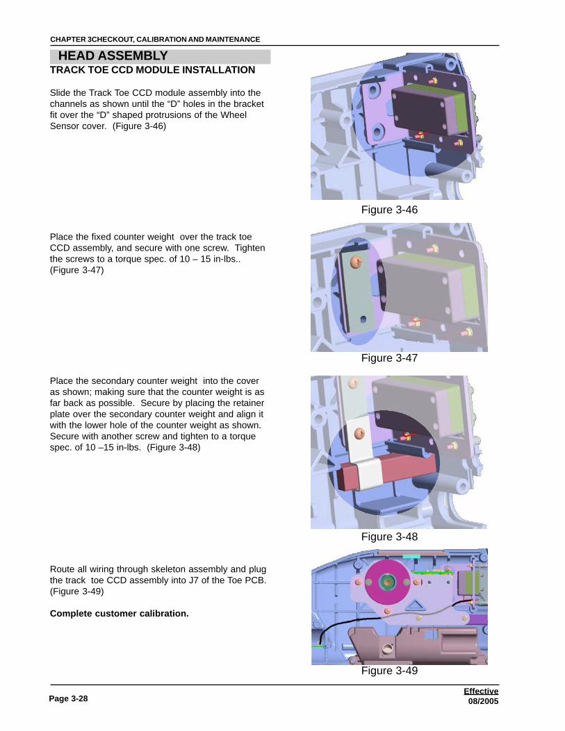
HEAD ASSEMBLYTRACK TOE CCD MODULE INSTALLATION
Slide the Track Toe CCD module assembly into thechannels as shown until the “D” holes in the bracketfit over the “D” shaped protrusions of the WheelSensor cover. (Figure 3-46)
Place the fixed counter weight over the track toeCCD assembly, and secure with one screw. Tightenthe screws to a torque spec. of 10 – 15 in-lbs..(Figure 3-47)
Place the secondary counter weight into the coveras shown; making sure that the counter weight is asfar back as possible. Secure by placing the retainerplate over the secondary counter weight and align itwith the lower hole of the counter weight as shown.Secure with another screw and tighten to a torquespec. of 10 –15 in-lbs. (Figure 3-48)
Route all wiring through skeleton assembly and plugthe track toe CCD assembly into J7 of the Toe PCB.(Figure 3-49)
Complete customer calibration.
Figure 3-46
Figure 3-47
Figure 3-48
Figure 3-49
Page 3-29
CHAPTER 3 CHECKOUT, CALIBRATION AND MAINTENANCE
Effective08/2005
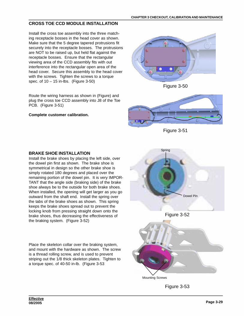
CROSS TOE CCD MODULE INSTALLATION
Install the cross toe assembly into the three match-ing receptacle bosses in the head cover as shown.Make sure that the 5 degree tapered protrusions fitsecurely into the receptacle bosses. The protrusionsare NOT to be raised up, but held flat against thereceptacle bosses. Ensure that the rectangularviewing area of the CCD assembly fits with outinterference into the rectangular open area of thehead cover. Secure this assembly to the head coverwith the screws. Tighten the screws to a torquespec. of 10 – 15 in-lbs. (Figure 3-50)
Route the wiring harness as shown in (Figure) andplug the cross toe CCD assembly into J8 of the ToePCB. (Figure 3-51)
Complete customer calibration.
BRAKE SHOE INSTALLATIONInstall the brake shoes by placing the left side, overthe dowel pin first as shown. The brake shoe issymmetrical in design so the other brake shoe issimply rotated 180 degrees and placed over theremaining portion of the dowel pin. It is very IMPOR-TANT that the angle side (braking side) of the brakeshoe always be to the outside for both brake shoes.When installed, the opening will get larger as you gooutward from the shaft end. Install the spring overthe tabs of the brake shoes as shown. This springkeeps the brake shoes spread out to prevent thelocking knob from pressing straight down onto thebrake shoes, thus decreasing the effectiveness ofthe braking system. (Figure 3-52)
Place the skeleton collar over the braking system,and mount with the hardware as shown. The screwis a thread rolling screw, and is used to preventstriping out the 1/8 thick skeleton plates. Tighten toa torque spec. of 40-50 in-lb. (Figure 3-53
Figure 3-50
Figure 3-51
Dowel Pin
Spring
Mounting Screws
Figure 3-52
Figure 3-53

Page 3-30
CHAPTER 3CHECKOUT, CALIBRATION AND MAINTENANCE
Effective08/2005
SECONDARY COUNTERWEIGHT INSTALLATION
Apply a thin coat of high pressure high lubricantsuch as “Moly-coat” lubricant to the fine counterweight screw prior to installation. Insert the finecounter weight screw into the counter weightbracket as well as the fine counter weight at thesame time as shown. Be sure of the orientationof the counter weight bracket in the relationship tothe screw weight as shown. (Figure 3-54)Install the ESNA nut to the end of the screw asshown and tighten until the esna nut touches thebracket.NOTE: DO NOT OVER TIGHTEN - THE
COUNTER WEIGHT MUST BE AL-LOWED TO MOVE BACK AND FORTHSMOOTHLY.
Install the counter weight assembly between theskeleton plates as shown, (Figure 3-55) andattach with four screws, tighten to a torque spec.of 15-20 in-lb. DO NOT over tighten thesescrews.
Figure 3-54
Figure 3-55
Page 3-31
CHAPTER 3 CHECKOUT, CALIBRATION AND MAINTENANCE
Effective08/2005
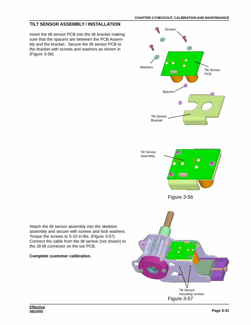
TILT SENSOR ASSEMBLY / INSTALLATION
Insert the tilt sensor PCB into the tilt bracket makingsure that the spacers are between the PCB Assem-bly and the bracket. Secure the tilt sensor PCB tothe bracket with screws and washers as shown in(Figure 3-56)
Attach the tilt sensor assembly into the skeletonassembly and secure with screws and lock washers.Torque the screws to 5-10 in-lbs. (Figure 3-57)Connect the cable from the tilt sensor (not shown) tothe J9 tilt connector on the toe PCB.
Complete customer calibration.
Screws
WashersTilt SensorPCB
Spacers
Tilt SensorBracket
Tilt SensorAssembly
Tilt Sensormounting screws
Figure 3-56
Figure 3-57

Page 3-32
CHAPTER 3CHECKOUT, CALIBRATION AND MAINTENANCE
Effective08/2005
SKELETON ASSEMBLY INSTALLATION
NOTE: The head cover comes equipped with brassultra-sonic welded inserts that have an internal nylonelastic lock washer built into the insert. NO otherlock washers are needed unless noted.
Install the skeleton assembly into the head covermake sure that the skeleton fits over and onto thethree “D” shaped mounting bosses. Make sure thatthe triangle cutout in the skeleton assembly plates fitover the “fixturing triangle” in the head cover, andthat the edges of the same skeleton plates locate upto the edges of the “J” shaped protrusion as shownin (Figure 3-58). The skeleton assembly MUSTreside flat, and not be raised up at any point. (Fig-ure 3-58)
Secure the skeleton assembly to the head cover withthree screws as shown. Tighten the screws totorque spec. 10 – 15 in-lbs. (Figure 3-59)
TOE BOARD INSTALLATION
LF/RR RF/LRJP2 open closeJP3 close open
Slide toe board into the slide protrusions of the headcover as shown – NOTE the orientation of toe PCBas shown. Make sure that the edge of the PCB isbetween the four locating tabs in the head cover asshown. (Figure 3-60)
Connect the cable from the tilt sensor to the J9connector on the toe PCB. Route this cable downand under the bearing extrusion of the skeletonassembly to the toe PCB. Connect the flat cablefrom the CCD Track Toe to the J7 connector on thetoe PCB. Route this cable down and under the tiltsensor assembly through the skeleton assembly tothe toe PCB. Connect the flat cable from the CCDCross Toe to the J8 connector on the toe PCB.Route this cable down the boom tube part of thehead cover to the toe PCB. Route the keyboard cable to J6 connector onthe toe PCB.
Flats on both sidesof fixturing “J”
Fixturing triangle
“D” bosses
Mounting screws
Triangle inskeleton assy’
Locating Tabs
Figure 3-58
Figure 3-59
Figure 3-60

Page 3-33
CHAPTER 3 CHECKOUT, CALIBRATION AND MAINTENANCE
Effective08/2005
Check for Sensor Updates & Complete customercalibration.MODULE INSTALLATIONInstall the cable assembly into the module as shown.(Figure 3-61)NOTE: MAKE SURE THAT THE SMALL TRI-
ANGLE RECEPTACLE IS ORIENTED ASSHOWN.
Install the screws through receptacle and the mod-ule. Tighten the screws to a torque spec. of 5 – 10in-lbs.
Install the hole plug as shown. Peel off overlay ofthe label cover and place “side down” over therectangular opening formed when the modules arejoined together. (Figure 3-62)
Install the module assembly into the head cover byaligning the groove in the module assembly with thelocating protrusion in the head cover (Figure 3-63).
Slide the module assembly down into the head coveruntil the tapered mtg. protrusions of the module arelocated in the tapered recess bosses of the headcovers. Make sure that you have the correct RF/Module assembly for the correct left or right headassembly. The connector should always be pointinginwards towards the center of the sensor as shown.(Figure 3-64)
Triangle
Hole Plug
Label cover
Tapered Mtg Hole
Recess for HeadCover Protrusion
Main PowerConnector
Figure 3-61
Figure 3-62
Figure 3-63
Figure 3-64

Page 3-34
CHAPTER 3CHECKOUT, CALIBRATION AND MAINTENANCE
Effective08/2005
REAR COVER INSTALLATIONSecure a fixed counter weight to the rear cover withthe provided screws and the esna nut . Tighten thescrews to torque spec. of 10 – 15 in-lbs.. Placethree 1” seal strips onto the rear cover approximatelyas shown. Slide the rear cover into the groove in thecover as shown. (Figure 65)
Place three hex nuts - item (29) into the smallpockets in the lower lip of the head cover as shown.Be sure that the flat of the hex nut is flush to theinside of the pocket as shown. (Figure 66)
Install the fixed counter weight and the secondarycounter weight into the cover as shown. Make surethat the secondary counter weight is as far back aspossible. Secure by placing the retainer plate overthe secondary counter weight and align it with thelower hole of the counter weight as shown.(Figure 3-67)Secure with another screw and tighten to a torquespec. of 10 –15 in-lbs.
Fixed counterweight
Rear cover
Seal Strips
Figure 3-65
Figure 3-66
Figure 3-67

Page 3-35
CHAPTER 3 CHECKOUT, CALIBRATION AND MAINTENANCE
Effective08/2005
HEAD COVER ASSEMBLYPlace the opposite head cover onto the other master head cover by aligning the grooves for the rear CCDassembly, the toe PCB, and the keypad. Gently push the covers together. The head covers should slidetogether with the skeleton mounting protrusions mating to the cutouts in the prior mounted skeleton assem-bly. Ensure that no cables are pinched or misalign any groove of the head covers to the toe PCB, keypad, orCCD track assembly. If the head covers do not mount flush to one another – check to see what is causingthe interference and correct. Attach the two head covers to one another with 11 screws as shown. Tightenthe screws to a torque spec. of 5 – 10 in-lbs. DO NOT overtighten the mounting screws. Press the bumpercover into the rectangular opening in the head cover until the rubber prongs are secured to the head cover.Press the level vial into the pocket located on the front of the head cover as shown. Peel away the carrierpaper from the brand label, and center it into the recess pocket of the wheel sensor cover. (Figure 68)
Attach the lower bumper cover to the assembledhead by stretching the bumper around the bottom ofthe head covers until the lip in the bumper is alignedwith the recess lip in the head covers. Press bothsides of the bumper’s lip into the recess lip of thehead covers. Insert three screws into the holes ofthe lower bumper cover and tighten to a torque spec.of 5-10 in-lbs.. Insert the brake knob assembly intothe opening of the assembled wheel sensor andtighten into the skeleton assembly. (Figure 69)
Mounting Screws
Level VialBumper Cover Brand Label
Lower Bumper Cover
Bumper Cover
Brake Knob
Figure 3-69
Figure 3-68

Page 3-36
CHAPTER 3CHECKOUT, CALIBRATION AND MAINTENANCE
Effective08/2005
ZERO ADJUST
Place the head into a clamp (or assembly fixture),and check the level of the head. Place a level vialonto the “zero” draft level pad as shown.(Figure 3-70)
To fine adjust the level of the head – insert a flathead screw-driver into the opening in the back of thehead assembly as shown. Turning the screw-driverclockwise will bring the counter weight to the rear ofthe head assembly, causing the head to tilt back-wards. Likewise turning the screw-driver counterclockwise will cause the weight to move forward inthe head causing the head to tilt forward. Adjust thehead until the level vial on the “zero” degree draftpad is level. (Figure 3-71)
NOTE: THE LEVEL VIAL IN THE BOOM TUBE ISUSED TO APPROXIMATE THE LEVEL OFTHE HEAD WHEN IT IS RAISED UP ON ALIFT WHERE THE OPERATOR CAN NOTSEE THE LEVEL INDICATOR ON THEKEYPAD.
“Zero” Draft Level Pad
Fine Counter WeightAdjustment Screw
Figure 3-70
Figure 3-71

Page 3-37
CHAPTER 3 CHECKOUT, CALIBRATION AND MAINTENANCE
Effective08/2005
OK Batteryfailure
Componentfailure
Information button
SENSOR FAILURE INDICATOR
This feature is only available on software revision 3.4 or higher. Before the design of this software it waspossible for a customer to perform and complete alignments with a inoperable component inside any of thewheel sensors. If the user was not aware of this it could/would cause inaccurate alignments and lead topremature tire wear. This software is designed to flag the user should a component inside a wheel sensorcompletly fail. A sensor diagnostic check is performed everytime the user chooses to perform a new wheelalignment from the Main Menu. The Main unit (PC) checks for proper Battery voltage providing the unit is acordless. It also checks both the cross toe and track toe CCD assemblies, it also checks the tilt sensor forfailures. Should a failure occur a dialogue box will appear with a display of each wheel sensor and it’sstatus. An information box will appear beside each wheel sensor and the user or technician can simply clickon the information icon to determine which component inside the wheel sensor is at fault. The fault compo-nent will only show up as a failure if sensor is completely dead, any marginal sensors will not cause the unitto flag an error. If the user chooses to press “OK” to bypass this “Flag” the dialogue box will not reappearuntil the user chooses to begin a new alignment.
The illustration above has flagged 3 wheel sensors with suspectedproblems. There are three possible senarios of display for eachsensor. Each wheel sensor that flags a suspected problem will beevident with either an “Explanation Point” or a “Battery” icon. Clickon the information button to see a dialogue illustration of the sus-pected component that has failed.
The figure to the right illustrates a failure to the tilt sensorassemby. See tilt sensor assembly and installation in thischapter for the the replacement procedures.

Page 3-38
CHAPTER 3CHECKOUT, CALIBRATION AND MAINTENANCE
Effective08/2005
The figure to the right illustrates a failure to the batteries.See the Cordless chapter in this manual for batteryreplacement.
The figure to the right illustrates a failure to the cross toeCCD sensor assemby. See CCD sensor assembly andinstallation in this chapter for the the replacement proce-dures.
The figure to the right illustrates a failure to the tilt sensorassemby. See tilt sensor assembly and installation in thischapter for the the replacement procedures.

Page 3-39
CHAPTER 3 CHECKOUT, CALIBRATION AND MAINTENANCE
Effective08/2005
FIRMWARE UPDATESNOTE: THIS FEATURE IS APPLICABLE TO VERSION I CCD WHEEL SENSORS!Changes are made to the firmware to take advantage of the new features of the PRO32 Aligner softwareupdate. If a download is needed for a sensor for the new software, it will be indicated on the “SensorUpdate” screen by the absence of a check mark. Firmware changes may also be made to the HIB PCBhowever these updates are made automatically during the software installation. Firmware updates mayinclude power save options for cordless, time delays for wired lifts or some of the many other featuresoffered in the CCD units. Firmware updates to the wheel sensors are not automatic and will require a smallamount of maintenance. Should any of these updates to the wheel sensor require the downloads beforeproper operation, the user will be instructed of this during the installation of the software. If a Main Proces-sor inside a wheel sensor is exchanged the technician should proceed to the Firmware Download page todetermine if that Main Processor should be updated. Re-calibration of the unit is not required once anupdate takes place, if calibration is required the user will be instructed of this during the software installation.All sensor updates should be made with the unit corded. At no time should a user attempt to complete asensor update with the cordless option.
Determining the Sensor/HIB Revision level.
1 Power up the aligner.
2 From the Main Menu click on the Maintenance tab.
3 From the Maintenance Menu click on the Measure-ment Data icon. Plug in all wheel sensors and verifythat all wheel sensors are sending/receiving datafrom the HIB box.
4 Click on the “Extended Data” tab.
5 Check each of the Revision levels of the MainProcessors inside the wheel sensors. Verify thateach are operating at the same revision level.
Determining if Sensors should be updated
1 Power up the aligner.
2 Using the cables supplied with the unit plug all 4wheel sensors into the HIB box.
NOTE: NEVER USE THE CORDLESS OPTION TOUPDATE FIRMWARE.
3 From the Main Menu click on the Maintenance tab.
4 From the Maintenance Menu click onthe Measurement Data icon. Verify thatall wheel sensors are sending/receivingdata from the HIB box.
5 Click on the “Sensor Update” (F6) iconon the toolbar.
Figure 3-72
Figure 3-73

Page 3-40
CHAPTER 3CHECKOUT, CALIBRATION AND MAINTENANCE
Effective08/2005
6. If the Sensors are updated with the latest Firmwareeach wheel sensor button will have a “Check Mark”.
7. If a newer revision of Firmware is available for any ofthe wheel sensors, the wheel sensor button will havean active icon.
NOTE: IT IS VERY IMPORTANT THAT ONCE THE FIRMWARE DOWNLOAD IS TAKING PLACE, THATTHE WHEEL SENSOR IS NOT UN-PLUGGED UNTIL THE DOWNLOAD FINISHES. A CHECKMARK ON THE WHEEL SENSOR BUTTON WILL INDICATE THAT THE PROCESS HAS BEENCOMPLETED.
8. Continue the Firmware upgrade by clicking on eachactive sensor button one at a time until each wheelsensor’s button is highlighted with a check mark.
9. After completing all updates the user must completelyexit the “Measurement Data” menu and return to theextended data page to check that all Main Processorsinside each wheel sensor are at the same revisionlevel. Failure to completely exit will not report firm-ware changes.
NOTE: IT IS NOT NECESSARY TO RESTART THE ALIGNMENTSOFTWARE AFTER THE FIRMWARE UPDATE.
NOTE: AFTER REPLACING A MAIN PROCESSOR INSIDE ANY WHEEL SENSOR, THE TECHNICIANSHOULD CHECK FOR AVAILABLE UPDATES.
Figure 3-74
Figure 3-75
Figure 3-76
Page 3-41
CHAPTER 3 CHECKOUT, CALIBRATION AND MAINTENANCE
Effective08/2005
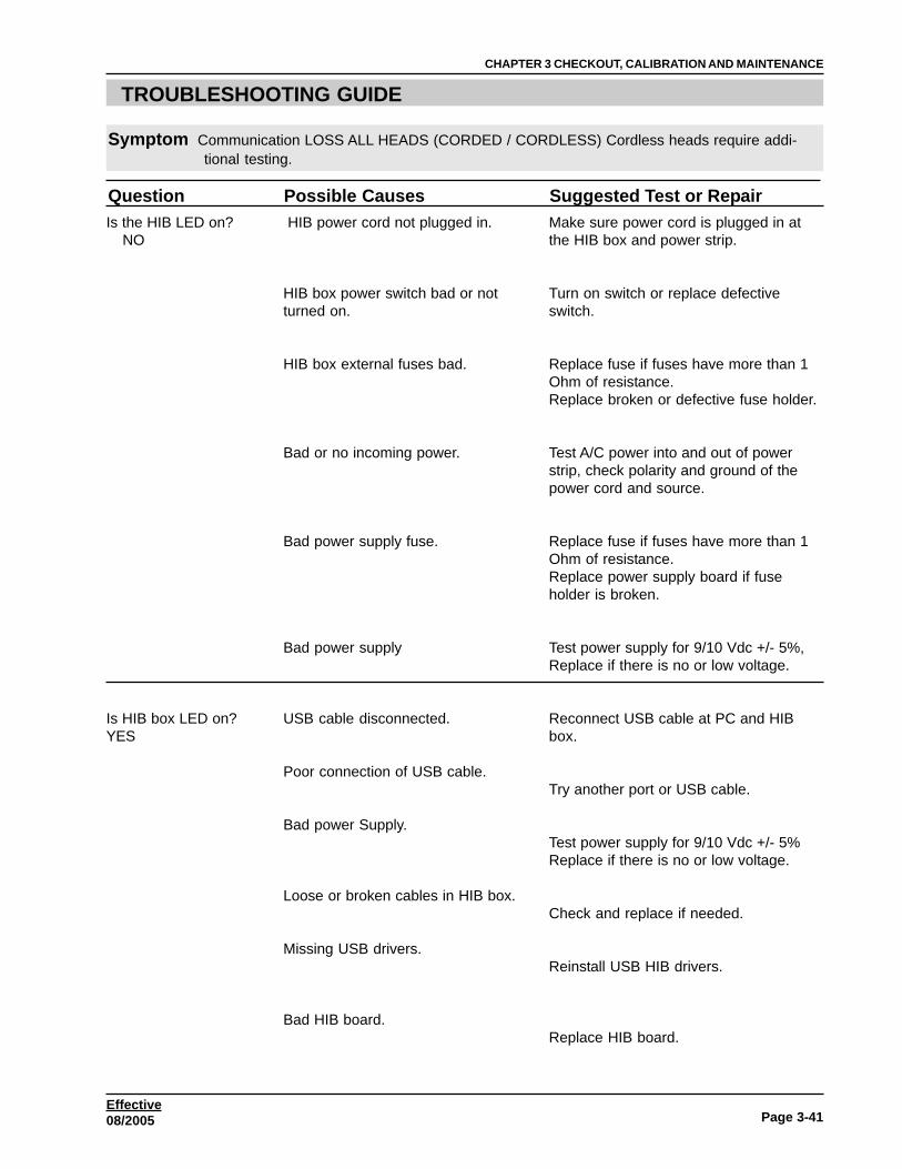
TROUBLESHOOTING GUIDE
Symptom Communication LOSS ALL HEADS (CORDED / CORDLESS) Cordless heads require addi-tional testing.
Question Possible Causes Suggested Test or RepairIs the HIB LED on? NO
Is HIB box LED on?YES
HIB power cord not plugged in.
HIB box power switch bad or notturned on.
HIB box external fuses bad.
Bad or no incoming power.
Bad power supply fuse.
Bad power supply
USB cable disconnected.
Poor connection of USB cable.
Bad power Supply.
Loose or broken cables in HIB box.
Missing USB drivers.
Bad HIB board.
Make sure power cord is plugged in atthe HIB box and power strip.
Turn on switch or replace defectiveswitch.
Replace fuse if fuses have more than 1Ohm of resistance.Replace broken or defective fuse holder.
Test A/C power into and out of powerstrip, check polarity and ground of thepower cord and source.
Replace fuse if fuses have more than 1Ohm of resistance.Replace power supply board if fuseholder is broken.
Test power supply for 9/10 Vdc +/- 5%,Replace if there is no or low voltage.
Reconnect USB cable at PC and HIBbox.
Try another port or USB cable.
Test power supply for 9/10 Vdc +/- 5%Replace if there is no or low voltage.
Check and replace if needed.
Reinstall USB HIB drivers.
Replace HIB board.
Page 3-42
CHAPTER 3CHECKOUT, CALIBRATION AND MAINTENANCE
Effective08/2005
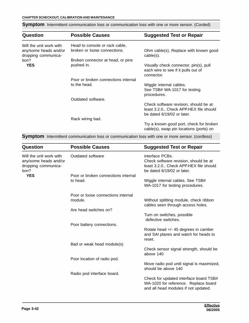
Symptom Intermittent communication loss or communication loss with one or more sensor. (Corded)
Question Possible Causes Suggested Test or Repair
Will the unit work withany/some heads and/ordropping communica-tion? YES
Head to console or rack cable,broken or loose connections.
Broken connector at head, or pinspushed in.
Poor or broken connections internalto the head.
Outdated software.
Rack wiring bad.
Ohm cable(s), Replace with known goodcable(s).
Visually check connector, pin(s), pulleach wire to see if it pulls out ofconnector.
Wiggle internal cables.See TSB# WA-1017 for testingprocedures.
Check software revision, should be atleast 3.2.0., Check APP.HEX file shouldbe dated 6/19/02 or later.
Try a known good port, check for brokencable(s), swap pin locations (ports) on
Symptom Intermittent communication loss or communication loss with one or more sensor. (cordless)
Question Possible Causes Suggested Test or Repair
Will the unit work withany/some heads and/ordropping communica-tion? YES
Outdated software
Poor or broken connections internalto head.
Poor or loose connections internalmodule.
Are head switches on?
Poor battery connections.
Bad or weak head module(s)
Poor location of radio pod.
Radio pod interface board.
interface PCBs.Check software revision, should be atleast 3.2.0., Check APP.HEX file shouldbe dated 6/19/02 or later.
Wiggle internal cables. See TSB#WA-1017 for testing procedures.
Without splitting module, check ribboncables seen through access holes.
Turn on switches, possible defective switches.
Rotate head +/- 45 degrees in camberand SAI planes and watch for heads toreset.
Check sensor signal strength, should beabove 140
Move radio pod until signal is maximized,should be above 140
Check for updated interface board TSB#WA-1020 for reference. Replace boardand all head modules if not updated.

Page 3-43
CHAPTER 3 CHECKOUT, CALIBRATION AND MAINTENANCE
Effective08/2005
Continued Intermittent communication loss or communication loss with one or more sensor. (cordless)
Question Possible Causes Suggested Test or Repair
Will unit work withcables but not incordless mode? YES
Are head switches on?
Poor battery connections
Bad batteries.
Poor location of radio pod
Radio interface board.
Bad console radio pod.
Poor connections internally. (heads)
Voice control module interference.
Dip switch setting.
Turn on switches possible defectiveswitches.
Rotate head +/- 45 degrees in camberand SAI planes and watch for heads toreset.
Test battery voltages should be morethan 3.8 Vdc. A fully charged batteryshould be 4.25 Vdc. Replace with knownfully charged battery.(See battery charger section for batterycharger problems)
Move radio pod till signal is maximized,console signal should be no less than140.
Check for updated interface board TSB#- 1020 for reference. Replace boardand all heads modules with update.
Console signal should not be less than140. Replace console radio pod.
Check internal cables for poor or brokenconnection. See TSB# WA-1017 fortesting procedures.
Disconnect power from voice module andremove battery from remote. Move voicemodule away from radio pod.
Try changing dip switches. (Dip switchesmust match in all sensors)

Page 3-44
CHAPTER 3CHECKOUT, CALIBRATION AND MAINTENANCE
Effective08/2005
Symptom Batteries not charging or low voltage after removing batteries from the charger.
Question Possible Causes Suggested Test or Repair
Are battery voltages atleast 4.25Vdc orhigher? NO
Power switch off or bad switch.
No A/C power to charger.
Bad fuses on power supply board orno 9Vdc from power supply.
Fuses bad on battery charger board.
Bad battery charger board.
Battery charger.
No A/C power to charger.
Bad fuses on power supply board orno 9Vdc from power supply.
Fuses bad on battery charger board.
Bad battery charger board.
Bad or weak batteries.
Bad LED board.
HIB power cord not plugged in.
Turn on switch or replace switch.
Test incoming voltages, Ohm externalfuses.
Replace fuses if they have more than 1Ohm of resistance, replace power supplyif less than 9/10Vdc +/- 5% output.
Replace fuses if they have more than 1Ohm of resistance.
If all the tests above are good, testcharger board, should be above 6Vdcand floating without a load.
Has the charger been updated with mylarstrips? Install strips,Replace charger board,Replace charger.
Test incoming voltage, Ohm externalfuses.
Replace fuses if they have more than 1Ohm resistance, replace power supply ifless than 9Vdc +/- 5% output.
Replace fuses if they have more than 1Ohm of resistance.
If all the tests above are good, testcharger board, should be above 6Vdcand floating without a load.
Replace batteries.
Replace LED board.
Make sure power cord is plugged in at
Are LED’s lights onflashing?
YES
Is charger LED’sLighting up?

Page 3-45
CHAPTER 3 CHECKOUT, CALIBRATION AND MAINTENANCE
Effective08/2005
Symptom PRO 32 always loads into the DEMO mode
Question Possible Causes Suggested Test or Repair
NOIs the HIB LED light on? NO
HIB box power switch notturned on.
HIB external fuses bad.
Bad or no incoming power.
Bad power supply fuse.
Bad power supply.
Bad HIB board.
USB cable disconnected.
Poor connection of USB cable.
Bad power supply.
Missing USB HIB drivers.
Bad HIB board.
Blocked toe path, Bad CCD camera,
the HIB box and power strip.Turn on switch or replace defectiveswitch.
Replace fuses if they have more than 1Ohm of resistance.Replace broken or defective fuse holder.
Test A/C power into and out of powerstrip, check polarity and ground of powercord and source.
Replace fuses if they have more than 1Ohm of resistance.Replace broken of defective fuse.
Test power supply for 9/10Vdc +/-5%Replace if there is no voltage or voltageis low.
Replace HIB.
Reconnect USB cable at PC and HIBbox.
Try another port or USB cable.
Test power supply for 9/10Vdc +/-5%,Replace if there is no voltage or voltageis low.
Reinstall USB HIB drivers
Replace HIB board
Is the HIB LED light on? YES

Page 3-46
CHAPTER 3CHECKOUT, CALIBRATION AND MAINTENANCE
Effective08/2005
Symptom Unit failed calibration with error messages
Error Message Possible Causes Suggested Test or Repair
Toe beam blocked or head disconnected.
Runout cross checkfailed.
Level the sensor
Calibration cameramemory read failed.
**Some calibrationfactors are out ofspecifications!
**Some calibrationfactors changed anexcessive amount!
Call a customer servicerepresentative todetermine the cause ofthe problem
Bad or broken cables, Poor commu-nication
Bent stub shafts, Bent Calibrationbar, Loose skeleton, Unstable tiltsensor,
Sensor not level, Bad or broken vial,bad tilt sensor
Bad communication, poor cable(s)connections, cordless communica-tions drop, Bad toe board
Bad or unstable CCD camera and ortilt sensors.
Bad or unstable CCD camera and ortilt sensors.
See the above with **
Check to make sure toe path(s) are notblocked.Check Raw sensor data for toe readingsand/or bad CCD cameras.Check broken or poor internal connec-tions see TSB# WA-1017.Check head cable(s) connections (swapcables)Update APP.HEX file (Cordless)
Check stub shafts, Check calibration bar,Check skeleton assembly for looseness.Check 4 degree camber change on barmake sure that camber ranges.Check camber on calibration for un-stable readings.Rotate calibration bar watch for exces-sive change.Replace tilt sensor.
Check level for Accuracy with smalllevel.Check SAI tilt sensor for change andrange.Check SAI sensor for stability
Redo calibration.Try different cables.Bad toe board.(Cordless units)Use cords for calibration
Reject, and redo calibration to confirmerror, replace affected Component(s)
Reject, and redo calibration to confirmerror, replace affected Component(s)