CHAPTER 21: Electromagnetic Induction and Faraday’s · PDF fileCHAPTER 21:...
25
© 2005 Pearson Education, Inc., Upper Saddle River, NJ. All rights reserve d. This material is protected under all copyright laws as they currently exist. No portion of this material may be reproduced, in any form or by any means, without permission in writing from the publisher. 124 CHAPTER 21: Electromagnetic Induction and Faraday’s Law Answers to Questions 1. The advantage of using many turns (N = large number) in Faraday’s experiments is that the emf and induced current are proportional to N, which makes it easier to experimentally measure those quantities. 2. Magnetic flux is proportional to the total number of magnetic field lines passing through an enclosed loop area: cos B BA , and so the flux is proportional to the magnitude of the magnetic field. Thus, they also have different units (magnetic field = Tesla = T; magnetic flux = Tm 2 = Wb). Another difference is that magnetic field is a vector (size and direction), while magnetic flux is a scalar (size). 3. Yes, a current is induced in the ring when you bring the south pole toward the ring. An emf and current are induced in the ring due to the changing magnetic flux (as the magnet gets closer to the ring, more magnetic field lines are going through the ring). No, a current is not induced in the ring when the magnet is held steady within the ring. An emf and current are not induced in the ring since the magnetic flux through the ring is not changing while the magnet is held steady. Yes, a current is induced in the ring when you withdraw the magnet. An emf and current are induced in the ring due to the changing magnetic flux (as you pull the magnet out of the ring toward you, fewer magnetic field lines are going through the ring). Using Lenz’s law and the Right Hand Rule, the direction of the induced current when you bring the south pole toward the ring is clockwise. In this case, the number of magnetic field lines coming through the loop and pointing toward you is increasing (remember, magnetic field lines point toward the south pole of the magnet). The induced current in the loop is going to try to oppose this change in flux and will attempt to create magnetic field lines through the loop that point away from you. A clockwise induced current will provide this opposing magnetic field. Using Lenz’s law and the Right Hand Rule again, the direction of the induced current when you withdraw the south pole from the ring is counterclockwise. In this case, the number of magnetic field lines coming through the loop and pointing toward you is decreasing. The induced current in the loop is going to try to oppose this change in flux and will attempt to create more magnetic field lines through the loop that point toward you. A counterclockwise induced current will provide this opposing magnetic field. 4. For the ring on the left side of the current-carrying wire there is no induced current. As the ring moves along parallel to the wire, the magnetic flux through the ring does not change, which means there is no induced emf and no induced current. For the ring on the right side of the current-carrying wire, the induced current is clockwise. As the ring moves away from the wire, the magnetic flux through the ring is decreasing (there are fewer magnetic field lines pointing into the loop). In an attempt to oppose this decrease (due to Lenz’s law), an emf and current will be induced in the ring in a clockwise direction (using the Right Hand Rule). 5. (a) Yes. As the battery is connected to the front loop and current starts to flow, it will create an increasing magnetic field that points away from you and down through the two loops. The second loop will try to oppose this increase in magnetic flux through it and an emf and current will be induced. (b) The induced current in the second loop starts to flow as soon as the current in the front loop starts to increase and create a magnetic field (basically, immediately upon the connection of the battery to the front loop).
Transcript of CHAPTER 21: Electromagnetic Induction and Faraday’s · PDF fileCHAPTER 21:...
© 2005 Pearson Education, Inc., Upper Saddle River, NJ. All rights reserved. This material is protected under all copyright laws as they currently exist. No portion of this material may be reproduced, in any form or by any means, without permission in writing from the publisher.
124
CHAPTER 21: Electromagnetic Induction and Faraday’s Law
Answers to Questions
1. The advantage of using many turns (N = large number) in Faraday’s experiments is that the emf and induced current are proportional to N, which makes it easier to experimentally measure those quantities.
2. Magnetic flux is proportional to the total number of magnetic field lines passing through an enclosed loop area: cosB BA , and so the flux is proportional to the magnitude of the magnetic field.
Thus, they also have different units (magnetic field = Tesla = T; magnetic flux = Tm2 = Wb). Another difference is that magnetic field is a vector (size and direction), while magnetic flux is a scalar (size).
3. Yes, a current is induced in the ring when you bring the south pole toward the ring. An emf and current are induced in the ring due to the changing magnetic flux (as the magnet gets closer to the ring, more magnetic field lines are going through the ring). No, a current is not induced in the ring when the magnet is held steady within the ring. An emf and current are not induced in the ring since the magnetic flux through the ring is not changing while the magnet is held steady. Yes, a current is induced in the ring when you withdraw the magnet. An emf and current are induced in the ring due to the changing magnetic flux (as you pull the magnet out of the ring toward you, fewer magnetic field lines are going through the ring). Using Lenz’s law and the Right Hand Rule, the direction of the induced current when you bring the south pole toward the ring is clockwise. In this case, the number of magnetic field lines coming through the loop and pointing toward you is increasing (remember, magnetic field lines point toward the south pole of the magnet). The induced current in the loop is going to try to oppose this change in flux and will attempt to create magnetic field lines through the loop that point away from you. A clockwise induced current will provide this opposing magnetic field. Using Lenz’s law and the Right Hand Rule again, the direction of the induced current when you withdraw the south pole from the ring is counterclockwise. In this case, the number of magnetic field lines coming through the loop and pointing toward you is decreasing. The induced current in the loop is going to try to oppose this change in flux and will attempt to create more magnetic field lines through the loop that point toward you. A counterclockwise induced current will provide this opposing magnetic field.
4. For the ring on the left side of the current-carrying wire there is no induced current. As the ring moves along parallel to the wire, the magnetic flux through the ring does not change, which means there is no induced emf and no induced current. For the ring on the right side of the current-carrying wire, the induced current is clockwise. As the ring moves away from the wire, the magnetic flux through the ring is decreasing (there are fewer magnetic field lines pointing into the loop). In an attempt to oppose this decrease (due to Lenz’s law), an emf and current will be induced in the ring in a clockwise direction (using the Right Hand Rule).
5. (a) Yes. As the battery is connected to the front loop and current starts to flow, it will create an increasing magnetic field that points away from you and down through the two loops. The second loop will try to oppose this increase in magnetic flux through it and an emf and current will be induced.
(b) The induced current in the second loop starts to flow as soon as the current in the front loop starts to increase and create a magnetic field (basically, immediately upon the connection of the battery to the front loop).
Giancoli Physics: Principles with Applications, 6th Edition
© 2005 Pearson Education, Inc., Upper Saddle River, NJ. All rights reserved. This material is protected under all copyright laws as they currently exist. No portion of this material may be reproduced, in any form or by any means, without permission in writing from the publisher.
125
(c) The current in the second loop stops flowing as soon as the current in the front loop becomes steady. Once the battery has increased the current in the front loop from zero to its steady-state value, then the magnetic field it creates is also steady. Since the magnetic flux through the second loop is no longer changing, the induced current goes to zero.
(d) The induced current in the second loop is counterclockwise. Since the increasing clockwise current in the front loop is causing an increase in the number of magnetic field lines down through the second loop, Lenz’s law states that the second loop will attempt to oppose this change in flux. To oppose this change, the Right Hand Rule says that a counterclockwise current will be induced in the second loop.
(e) Yes. Since both loops carry currents and create magnetic fields while the current in the front loop is increasing from the battery, these two magnetic fields will interact and put a force on each of the loops.
(f) The force between the two loops will repel each other. The front loop is creating a magnetic field pointed toward the second loop. This changing magnetic field induces a current in the second loop to oppose the increasing magnetic field and this induced current creates a magnetic field pointing toward the front loop. These two magnetic fields will act like two north poles pointing at each other and repel.
6. (a) The induced current in RA is to the right as coil B is moved toward coil A. As B approaches A, the magnetic flux through coil A increases (there are now more magnetic field lines in coil A pointing to the left). Coil A attempts to oppose this increase in flux, and the induced emf creates a current to produce a magnetic field pointing to the right through the center of the coil. A current through RA to the right will produce this opposing field.
(b) The induced current in RA is to the left as coil B is moved away from coil A. As B recedes from A, the magnetic flux through coil A decreases (there are now fewer magnetic field lines in coil A pointing to the left). Coil A attempts to oppose this decrease in flux, and the induced emf creates a current to produce a magnetic field pointing to the left through the center of the coil. A current through RA to the left will produce this opposing field.
(c) The induced current in RA is to the left as RB in coil B is increased. As RB increases, the current in coil B decreases, which also decreases the magnetic field coil B produces. As the magnetic field from coil B decreases, the magnetic flux through coil A decreases (there are now fewer magnetic field lines in coil A pointing to the left). Coil A attempts to oppose this decrease in flux, and the induced emf creates a current to produce a magnetic field pointing to the left through the center of the coil. A current through RA to the left will produce this opposing field.
7. As the signal in the wire varies in time, it creates changing magnetic fields that emanate from the wire. If there were external magnetic fields nearby, these could interact with the signal wire’s magnetic fields and cause interference or noise in the signal. With the “shield” in place around the signal wire carrying the return current, the net current in the wire, as seen by the outside world, would be zero and, thus, the wire would not emanate a magnetic field. In turn, the external magnetic fields would not have any signal field to interact with and the interference and noise in the signal would be reduced.
8. One advantage of placing the two insulated wires carrying ac close together is that whatever magnetic fields are created by the changing current moving one way in one wire is approximately cancelled out by the magnetic field created by the current moving in the opposite direction in the second wire. Also, since large loops of wire in a circuit can generate a large self-induced back emf, by placing the two wires close to each other, or even twisting them about each other, the effective area of the current loop is decreased and the induced current is minimized.
Chapter 21 Electromagnetic Induction and Faraday’s Law
© 2005 Pearson Education, Inc., Upper Saddle River, NJ. All rights reserved. This material is protected under all copyright laws as they currently exist. No portion of this material may be reproduced, in any form or by any means, without permission in writing from the publisher.
126
9. As the refrigerator motor first starts up, there is a small back emf in the circuit (back emf is proportional to the rotation speed of the motor), which allows for a large amount of current to flow to the refrigerator. This large current overtaxes the source and diminishes the current to all of the devices on the circuit, including the lights. As the refrigerator motor speeds up to its normal operational speed, the back emf increases to its normal level and the current delivered to the refrigerator is now limited to its usual amount. This current is no longer enough to overburden the source and all of the devices in the room go back to normal. Thus, it appears that the lights flicker just when the refrigerator motor first starts up. A heater, on the other hand, draws a large amount of current (it is a very low-resistance device) at all times. The source is then continually overtaxed and the other devices on the same circuit remain dimmed all the while that the heater is operating. In an ideal situation, the source could provide any amount of current to the whole circuit in either situation. In reality, though, the higher currents in the wires causes bigger losses of energy along the way to the devices and the lights dim.
10. Figure 21-17 shows that the induced current in the upper armature segment points into the page. This can be shown using a Right Hand Rule: The charges in the top metal armature segment are moving in the direction of the velocity shown with the green arrow (up and to the right) and these moving charges are in a magnetic field shown with the blue arrows (to the right), and then the Right Hand Rule says that the charges experience a force into the page producing the induced current. This induced current is also in the magnetic field. Using another Right Hand Rule, a current-carrying wire, with the current going into the page (as in the upper armature segment), in a magnetic field pointed to the right, will experience a force in a downward direction. Thus, there is a counter-clockwise torque on the armature while it is rotation in a clockwise direction. The back emf is opposing the motion of the armature during its operation.
11. Yes, eddy current brakes will work on metallic wheels, such as copper and aluminum. Eddy current brakes do not need to act on ferromagnetic wheels. The external magnetic field of the eddy brake just needs to interact with the “free” conduction electrons in the metal wheels to make it work. First, the magnetic field creates eddy currents in the moving metal wheel using the free conduction electrons (the Right Hand Rule says moving charges in a magnetic field will experience a magnetic force, making them move, and creating an eddy current). This eddy current is also in the braking magnetic field. The Right Hand Rule says these currents will experience a force opposing the original motion of the piece of metal and the eddy current brake will begin to slow the wheel. Good conductors, such as copper and aluminum, have many free conduction electrons and will allow large eddy currents to be created, which in turn will provide good braking results.
12. As the pieces of conducting materials slide down the incline past permanent magnets, the “free” conduction electrons in the pieces are forced to create eddy currents (the Right Hand Rule says moving charges in a magnetic field will experience a magnetic force, making them move, and creating an eddy current). These eddy currents are not created in the non-metallic pieces. These eddy currents are also moving through the magnetic fields of the permanent magnets and the Right Hand Rule says these currents will experience a magnetic force opposing the original motion of the pieces of metal. Thus, the metallic pieces will be slowed as they slide down the incline, while the non-metallic pieces will continue to accelerate the entire time. Since the metallic pieces have been slowed, they will basically just drop off of the end of the incline and you would put a “metal bin” directly below the end to catch the metal pieces. The non-metallic pieces, on the other hand, will come off the end of the incline with a high speed and overshoot the “metal bin” and be caught in a “non-metal bin” sitting farther away from the end.
Giancoli Physics: Principles with Applications, 6th Edition
© 2005 Pearson Education, Inc., Upper Saddle River, NJ. All rights reserved. This material is protected under all copyright laws as they currently exist. No portion of this material may be reproduced, in any form or by any means, without permission in writing from the publisher.
127
13. The slots cut into the piece of pivoted metal bar confine the induced eddy currents to many very small loops, instead of just one large loop. These smaller current loops have less magnetic flux due to their smaller areas, which creates less emf and smaller eddy currents. The smaller eddy currents then experience a smaller opposing force to the motion of the metal bar. Thus, the slotted bar falls more quickly through the magnetic field.
14. As you try to move the aluminum sheet out of the magnetic field, areas of the sheet that used to be in B = 0 regions start to gain magnetic flux. This changing flux will induce currents in the “free” conduction electrons of the aluminum to oppose the change. These eddy currents are then acted on by the magnetic field and the resulting force opposes the motion of the aluminum sheet. Thus, it requires some amount of force to remove the sheet from between the poles.
15. As a magnet falls through a metal tube, an increase in the magnetic flux is created in the areas ahead of it in the tube. This flux change induces a current to flow around the tube walls to create an opposing magnetic field in the tube (Lenz’s law). This induced magnetic field pushes against the falling magnet and causes it to slow down. The opposing magnetic field cannot cause the magnet to actually come to a stop, since then the flux would become a constant and the induced current would disappear and so would the opposing magnetic field. Thus, the magnet reaches a state of equilibrium and falls at a constant terminal velocity.
16. As the metal bar enters (or leaves) the magnetic field during the swinging motion, areas of the metal bar experience a change in magnetic flux. This changing flux induces eddy currents with the “free” conduction electrons in the metal bar. These eddy currents are then acted on by the magnetic field and the resulting force opposes the motion of the swinging metal bar. This opposing force acts on the bar no matter which direction it is swinging through the magnetic field, thus damping the motion during both the to and fro portions of the swing.
17. To determine the ratio of turns on the two coils of a transformer without taking it apart, apply a known ac input source voltage to one pair of leads and carefully measure the output voltage across the other two leads. Then, Vsource/Voutput = Ns/No, which provides us with the ratio of turns on the two coils. To determine which leads are paired with which, you could use an ohmmeter, since the two source wires are in no way electrically connected to the two output wires. If the resistance between two wires is very small, then those two wires are a pair. If the resistance between two wires is infinite, then those two wires are not a pair.
18. Higher voltages, such as 600 V or 1200 V, would be dangerous if they were used in household wires! Such a large potential difference between household wires and anything that is grounded (other wires, people, etc.) would more easily cause electrical breakdown of the air and then much more sparking would occur. Basically, this would supply each of the charges in the household wires with much more energy than the lower voltages, which would allow them to arc to other conductors. This would increase the possibility of more short circuits and accidental electrocutions.
19. When 120 V dc is applied to the transformer, there is no induced back emf that would usually occur with 120 V ac. This means that the 120 V dc encounters much less resistance than the 120 V ac, which would cause too much current to flow through the transformer. This large amount of current would overheat the coils, which are usually wound with many loops of very fine wire, and could melt the insulation and burn out or short out the transformer.
20. (a) To create the largest amount of mutual inductance with two flat circular coils of wire, you would place them face-to-face and very close to each other. This way, almost all of the magnetic flux from one coil also goes through the other coil.
Chapter 21 Electromagnetic Induction and Faraday’s Law
© 2005 Pearson Education, Inc., Upper Saddle River, NJ. All rights reserved. This material is protected under all copyright laws as they currently exist. No portion of this material may be reproduced, in any form or by any means, without permission in writing from the publisher.
128
(b) To create the least amount of mutual inductance with two flat circular coils, you would place them with their faces at right angles. This way, almost none of the magnetic flux from one coil goes through the other coil.
21. (a) No. Although the current through an LR circuit is described by 1t
L RI eR
E, we can
substitute maxIR
E. Thus, a given fraction of a maximum possible current, maxI I , is equal to
1t
L Re and is independent of the battery emf.
(b) Yes. Since 1t
L RI eR
E, if a given value of the current is desired, it is dependent on the
value of the battery emf.
22. (a) Yes. (b) Yes. The rms voltages across either an inductor or a capacitor of an LRC circuit can be greater
than the rms source voltage because the different voltages are out of phase with each other. At any given instant, the voltage across either the inductor or the capacitor could be negative, for example, thus allowing for a very large positive voltage on the other device. (The rms voltages, however, are always positive by definition.)
23. (a) The frequency of the source emf does not affect the impedance of a pure resistance. The impedance of a pure resistance is independent of the source emf frequency.
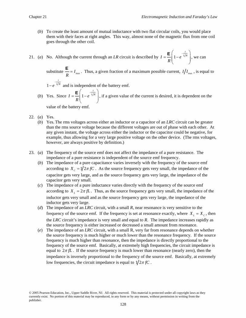
(b) The impedance of a pure capacitance varies inversely with the frequency of the source emf according to 1 2CX fC . As the source frequency gets very small, the impedance of the
capacitor gets very large, and as the source frequency gets very large, the impedance of the capacitor gets very small.
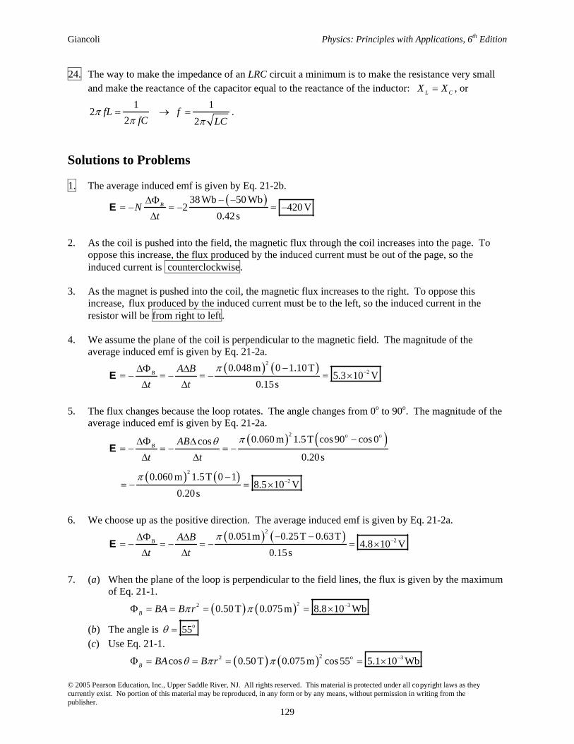
(c) The impedance of a pure inductance varies directly with the frequency of the source emf according to 2LX fL . Thus, as the source frequency gets very small, the impedance of the
inductor gets very small and as the source frequency gets very large, the impedance of the inductor gets very large.
(d) The impedance of an LRC circuit, with a small R, near resonance is very sensitive to the frequency of the source emf. If the frequency is set at resonance exactly, where L CX X , then
the LRC circuit’s impedance is very small and equal to R. The impedance increases rapidly as the source frequency is either increased or decreased a small amount from resonance.
(e) The impedance of an LRC circuit, with a small R, very far from resonance depends on whether the source frequency is much higher or much lower than the resonance frequency. If the source frequency is much higher than resonance, then the impedance is directly proportional to the frequency of the source emf. Basically, at extremely high frequencies, the circuit impedance is equal to 2 fL . If the source frequency is much lower than resonance (nearly zero), then the impedance is inversely proportional to the frequency of the source emf. Basically, at extremely low frequencies, the circuit impedance is equal to 1 2 fC .
Giancoli Physics: Principles with Applications, 6th Edition
© 2005 Pearson Education, Inc., Upper Saddle River, NJ. All rights reserved. This material is protected under all copyright laws as they currently exist. No portion of this material may be reproduced, in any form or by any means, without permission in writing from the publisher.
129
24. The way to make the impedance of an LRC circuit a minimum is to make the resistance very small and make the reactance of the capacitor equal to the reactance of the inductor: L CX X , or
1 12
2 2fL f
fC LC.
Solutions to Problems
1. The average induced emf is given by Eq. 21-2b. 38 Wb 50 Wb
2 420 V0.42s
BNt
E
2. As the coil is pushed into the field, the magnetic flux through the coil increases into the page. To oppose this increase, the flux produced by the induced current must be out of the page, so the induced current is counterclockwise.
3. As the magnet is pushed into the coil, the magnetic flux increases to the right. To oppose this increase, flux produced by the induced current must be to the left, so the induced current in the resistor will be from right to left.
4. We assume the plane of the coil is perpendicular to the magnetic field. The magnitude of the average induced emf is given by Eq. 21-2a.
2
20.048 m 0 1.10 T5.3 10 V
0.15sB A B
t tE
5. The flux changes because the loop rotates. The angle changes from 0o to 90o. The magnitude of the average induced emf is given by Eq. 21-2a.
2 o o
2
2
0.060 m 1.5T cos 90 cos 0cos
0.20s
0.060 m 1.5T 0 1 8.5 10 V
0.20s
B AB
t tE
6. We choose up as the positive direction. The average induced emf is given by Eq. 21-2a. 2
20.051m 0.25T 0.63T4.8 10 V
0.15sB A B
t tE
7. (a) When the plane of the loop is perpendicular to the field lines, the flux is given by the maximum of Eq. 21-1.
22 30.50 T 0.075 m 8.8 10 WbB BA B r
(b) The angle is o55
(c) Use Eq. 21-1. 22 o 3cos 0.50 T 0.075 m cos 55 5.1 10 WbB BA B r

Chapter 21 Electromagnetic Induction and Faraday’s Law
© 2005 Pearson Education, Inc., Upper Saddle River, NJ. All rights reserved. This material is protected under all copyright laws as they currently exist. No portion of this material may be reproduced, in any form or by any means, without permission in writing from the publisher.
130
8. (a) As the resistance is increased, the current in the outer loop will decrease. Thus the flux through the inner loop, which is out of the page, will decrease. To oppose this decrease, the induced current in the inner loop will produce a flux out of the page, so the direction of the induced current will be counterclockwise.
(b) If the small loop is placed to the left, the flux through the small loop will be into the page and will decrease. To oppose this decrease, the induced current in the inner loop will produce a flux into the page, so the direction of the induced current will be clockwise.
9. (a) The increasing current in the wire will cause an increasing field out of the page through the loop. To oppose this increase, the induced current in the loop will produce a flux into the page, so the direction of the induced current will be clockwise.
(b) The decreasing current in the wire will cause a decreasing field out of the page through the loop. To oppose this decrease, the induced current in the loop will produce a flux out of the page, so the direction of the induced current will be counterclockwise.
(c) The decreasing current in the wire will cause a decreasing field into the page through the loop. To oppose this decrease, the induced current in the loop will produce a flux into the page, so the direction of the induced current will be clockwise.
(d) Because the current is constant, there will be no change in flux, so the induced current will be zero.
10. As the solenoid is pulled away from the loop, the magnetic flux to the right through the loop decreases. To oppose this decrease, the flux produced by the induced current must be to the right, so the induced current is counterclockwise as viewed from the right end of the solenoid.
11. (a) The average induced emf is given by Eq. 21-2a. 2
20.060 m 0.45T 0.52 T6.1 10 V
0.18sB A B
t tE
(b) The positive result for the induced emf means the induced field is away from the observer, so the induced current is clockwise.
12. (a) Because the velocity is perpendicular to the magnetic field and the rod, we find the induced emf from Eq. 21-3.
20.800 T 0.120 m 0.150 m s 1.44 10 VBLvE
(b) Because the upward flux is increasing, the induced flux will be into the page, so the induced current is clockwise. Thus the induced emf in the rod is down, which means that the electric field will be down. The electric field is the induced voltage per unit length.
21.44 10 V0.120 V m , down
0.120 mE
l
E
13. (a) The magnetic flux through the loop is into the paper and decreasing, because the area is decreasing. To oppose this decrease, the induced current in the loop will produce a flux into the paper, so the direction of the induced current will be clockwise.
(b) The average induced emf is given by Eq. 21-2a. 2 2
2 2
0.75T 0.100 m 0.030 m
0.50s
4.288 10 V 4.3 10 V
BB A
t tE
Giancoli Physics: Principles with Applications, 6th Edition
© 2005 Pearson Education, Inc., Upper Saddle River, NJ. All rights reserved. This material is protected under all copyright laws as they currently exist. No portion of this material may be reproduced, in any form or by any means, without permission in writing from the publisher.
131
(c) We find the average induced current from Ohm’s law. 2
24.288 10 V1.7 10 A
2.5
VI
R
14. (a) The velocity is found from Eq. 21-3.
0.12 V
1.0 m s
0.90T 0.132 mBlv v
Bl
EE
(b) Because the outward flux is increasing, the induced flux will be into the page, so the induced current is clockwise. Thus the induced emf in the rod is down, which means that the electric field will be down. The magnitude of the electric field is the induced voltage per unit length.
0.12 V0.91V m , down
0.132 mE
l
E
15. As the loop is pulled from the field, the flux through the loop decreases, causing an induced EMF whose magnitude is given by Eq. 21-3, BlvE . Because the inward flux is decreasing, the induced flux will be into the page, so the induced current is clockwise, given by I RE . Because this current in the left-hand side of the loop is in a downward magnetic field, there will be a magnetic force to the left. To keep the rod moving, there must be an equal external force to the right, given by F IlB .
2 22 2 0.550 T 0.350 m 3.40 m s0.548 N
0.230
Blv B l vF IlB lB lB
R R R
E
16. The emf induced in the short coil is given by Eq. 21-2b, where N is the number of loops in the short coil, and the flux change is measured over the area of the short coil. The magnetic flux comes from the B-field created by the solenoid. The field in a solenoid is given by Eq. 20-8,
0 solenoid solenoidB IN l , and the changing current in the solenoid causes the field to change.
0 solenoidshort short
solenoidshort short 0 short solenoid short
solenoid
27
44 10 T m A 10 500 0.0125 m 5.0 A
1.0 10 V0.25 m 0.60s
INN A
lN A B N N A I
t t l tE
17. (a) Because the velocity is perpendicular to the magnetic field and the rod, we find the induced emf from Eq. 21-3.
0.35T 0.300 m 1.6 m s 0.168 V 0.17 VBlvE
(b) Find the induced current from Ohm’s law.
3 30.168 V6.11 10 A 6.1 10 A
27.5I
R
E
(c) The induced current in the rod will be down. Because this current is in an upward magnetic field, there will be a magnetic force to the left. To keep the rod moving, there must be an equal external force to the right, given by Eq. 20-2.
3 46.11 10 A 0.300 m 0.35T 6.4 10 NF IlB
Chapter 21 Electromagnetic Induction and Faraday’s Law
© 2005 Pearson Education, Inc., Upper Saddle River, NJ. All rights reserved. This material is protected under all copyright laws as they currently exist. No portion of this material may be reproduced, in any form or by any means, without permission in writing from the publisher.
132
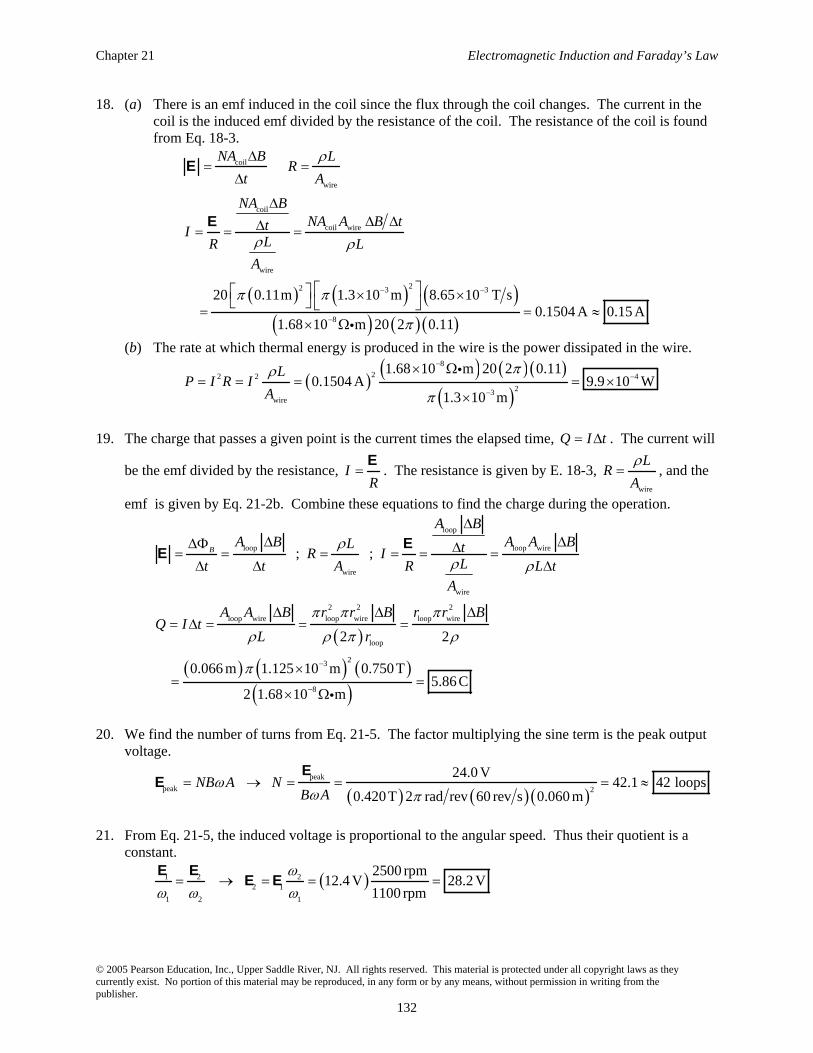
18. (a) There is an emf induced in the coil since the flux through the coil changes. The current in the coil is the induced emf divided by the resistance of the coil. The resistance of the coil is found from Eq. 18-3.
coil
wire
coil
coil wire
wire
22 3 3
8
20 0.11m 1.3 10 m 8.65 10 T s
0.1504 A 0.15 A1.68 10 m 20 2 0.11
NA B LR
t A
NA BNA A B ttI
LR LA
E
E
(b) The rate at which thermal energy is produced in the wire is the power dissipated in the wire. 8
22 2 4
23wire
1.68 10 m 20 2 0.110.1504 A 9.9 10 W
1.3 10 m
LP I R I
A
19. The charge that passes a given point is the current times the elapsed time, Q I t . The current will
be the emf divided by the resistance, IR
E. The resistance is given by E. 18-3,
wire
LR
A, and the
emf is given by Eq. 21-2b. Combine these equations to find the charge during the operation.
loop
loop loop wire
wire
wire
2 2 2
loop wire loop wire loop wire
loop
23
8
; ;
2 2
0.066 m 1.125 10 m 0.750 T 5.86 C
2 1.68 10 m
B
A BA B A A BL tR I
Lt t A R L tA
A A B r r B r r BQ I t
L r
EE
20. We find the number of turns from Eq. 21-5. The factor multiplying the sine term is the peak output voltage.
peak
peak 2
24.0 V
42.1 42 loops0.420T 2 rad rev 60 rev s 0.060 m
NB A NB A
EE
21. From Eq. 21-5, the induced voltage is proportional to the angular speed. Thus their quotient is a constant.
1 2 22 1
1 2 1
2500 rpm
12.4 V 28.2 V1100 rpm
E EE E
Giancoli Physics: Principles with Applications, 6th Edition
© 2005 Pearson Education, Inc., Upper Saddle River, NJ. All rights reserved. This material is protected under all copyright laws as they currently exist. No portion of this material may be reproduced, in any form or by any means, without permission in writing from the publisher.
133
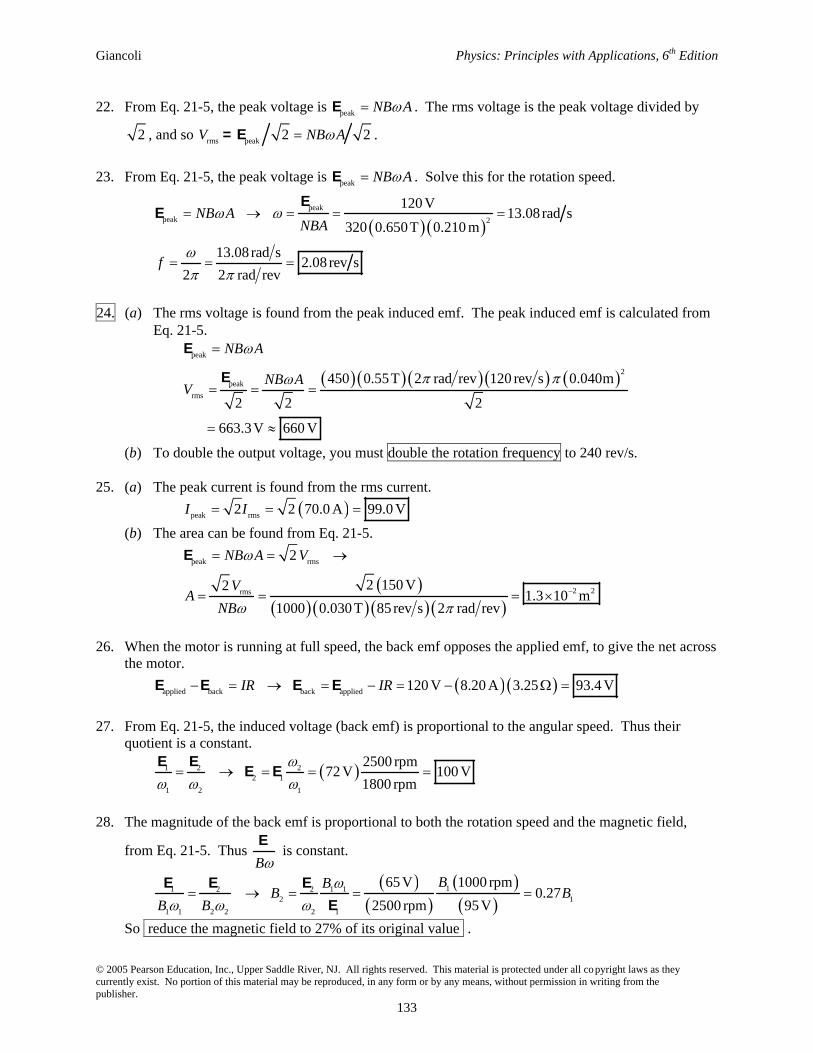
22. From Eq. 21-5, the peak voltage is peak NB AE . The rms voltage is the peak voltage divided by
2 , and so rms peak 2 2V NB A= E .
23. From Eq. 21-5, the peak voltage is peak NB AE . Solve this for the rotation speed.
peak
peak 2
120 V
13.08 rad s
320 0.650T 0.210 m
13.08 rad s2.08 rev s
2 2 rad rev
NB ANBA
f
EE
24. (a) The rms voltage is found from the peak induced emf. The peak induced emf is calculated from Eq. 21-5.
peak
2
peak
rms
450 0.55T 2 rad rev 120 rev s 0.040m
2 2 2
663.3V 660 V
NB A
NB AV
E
E
(b) To double the output voltage, you must double the rotation frequency to 240 rev/s.
25. (a) The peak current is found from the rms current.
peak rms2 2 70.0 A 99.0 VI I
(b) The area can be found from Eq. 21-5.
peak rms
2 2rms
2
2 150 V21.3 10 m
1000 0.030 T 85 rev s 2 rad rev
NB A V
VA
NB
E
26. When the motor is running at full speed, the back emf opposes the applied emf, to give the net across the motor.
applied back back applied
120 V 8.20 A 3.25 93.4 VIR IRE E E E
27. From Eq. 21-5, the induced voltage (back emf) is proportional to the angular speed. Thus their quotient is a constant.
1 2 22 1
1 2 1
2500 rpm
72 V 100 V1800 rpm
E EE E
28. The magnitude of the back emf is proportional to both the rotation speed and the magnetic field,
from Eq. 21-5. Thus B
E is constant.
11 2 2 1 12 1
1 1 2 2 2 1
65 V 1000 rpm
0.272500 rpm 95 V
BBB B
B B
E E E
E
So reduce the magnetic field to 27% of its original value .
Chapter 21 Electromagnetic Induction and Faraday’s Law
© 2005 Pearson Education, Inc., Upper Saddle River, NJ. All rights reserved. This material is protected under all copyright laws as they currently exist. No portion of this material may be reproduced, in any form or by any means, without permission in writing from the publisher.
134
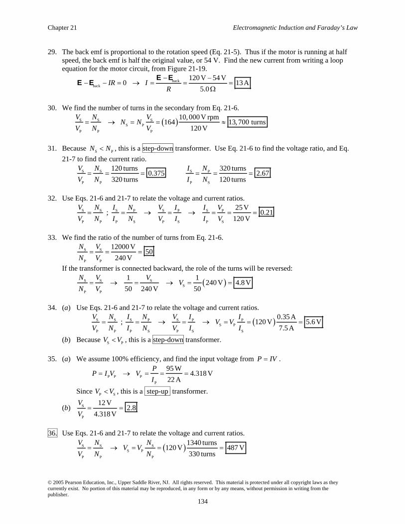
29. The back emf is proportional to the rotation speed (Eq. 21-5). Thus if the motor is running at half speed, the back emf is half the original value, or 54 V. Find the new current from writing a loop equation for the motor circuit, from Figure 21-19.
backback
120 V 54 V0 13A
5.0IR I
R
E EE E
30. We find the number of turns in the secondary from Eq. 21-6.
S S SS P
P P P
10, 000 V rpm
164 13,700 turns120 V
V N VN N
V N V
31. Because S PN N , this is a step-down transformer. Use Eq. 21-6 to find the voltage ratio, and Eq.
21-7 to find the current ratio.
S S S P
P P P S
120 turns 320 turns0.375 2.67
320 turns 120 turns
V N I N
V N I N
32. Use Eqs. 21-6 and 21-7 to relate the voltage and current ratios.
S S S S SP P P
P P P S P S P S
25 V
; 0.21120 V
V N I V IN I V
V N I N V I I V
33. We find the ratio of the number of turns from Eq. 21-6.
S S
P P
12000 V50
240 V
N V
N V
If the transformer is connected backward, the role of the turns will be reversed:
S S SS
P P
1 1
240 V 4.8 V50 240 V 50
N V VV
N V
34. (a) Use Eqs. 21-6 and 21-7 to relate the voltage and current ratios.
S S S SP P PS P
P P P S P S S
0.35 A
; 120 V 5.6 V7.5 A
V N I VN I IV V
V N I N V I I
(b) Because S PV V , this is a step-down transformer.
35. (a) We assume 100% efficiency, and find the input voltage from P IV .
P P P
P
95 W
4.318 V22 A
PP I V V
I
Since P SV V , this is a step-up transformer.
(b) S
P
12 V2.8
4.318 V
V
V
36. Use Eqs. 21-6 and 21-7 to relate the voltage and current ratios.
S S SS P
P P P
1340 turns
120 V 487 V330 turns
V N NV V
V N N
Giancoli Physics: Principles with Applications, 6th Edition
© 2005 Pearson Education, Inc., Upper Saddle River, NJ. All rights reserved. This material is protected under all copyright laws as they currently exist. No portion of this material may be reproduced, in any form or by any means, without permission in writing from the publisher.
135
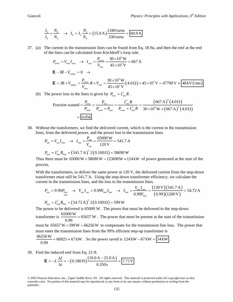
S SPP S
P S P
1340 turns
15.0 A 60.9 A
330 turns
I NNI I
I N N
37. (a) The current in the transmission lines can be found from Eq. 18-9a, and then the emf at the end
of the lines can be calculated from Kirchhoff’s loop rule. 6
towntown rms rms rms 3
rms
output
63town
output rms 3
rms
30 10 W 667 A
45 10 V
0
30 10 W4.0 45 10 V 47700 V 48 kV rms
45 10 V
PP V I I
V
IR V
PIR V R V
V
E
E
(b) The power loss in the lines is given by 2
loss rmsP I R . 22
loss loss rms
22 6total town loss town rms
667 A 4.0Fraction wasted
30 10 W 667 A 4.0
0.056
P P I R
P P P P I R
38. Without the transformers, we find the delivered current, which is the current in the transmission lines, from the delivered power, and the power lost in the transmission lines.
outout out line line
out
22
lost line line
65000 W
541.7 A120 V
541.7 A 2 0.100 58690 W
PP V I I
V
P I R
Thus there must be 65000 W 58690 W 123690W 124 kW
of power generated at the start of the process.
With the transformers, to deliver the same power at 120 V, the delivered current from the step-down transformer must still be 541.7 A. Using the step-down transformer efficiency, we calculate the current in the transmission lines, and the loss in the transmission lines.
out outout line out out line line line
end line
22
lost line line
120 V 541.7 A0.99 0.99 54.72 A
0.99 0.99 1200 V
54.72 A 2 0.100 599 W
V IP P V I V I I
V
P I R
The power to be delivered is 65000 W. The power that must be delivered to the step-down
transformer is 65000 W
65657 W0.99
. The power that must be present at the start of the transmission
must be 65657 W 599 W 66256 W to compensate for the transmission line loss. The power that must enter the transmission lines from the 99% efficient step-up transformer is 66256 W
66925 67 kW0.99
. So the power saved is 124 kW 67 kW 54 kW .
39. Find the induced emf from Eq. 21-9. 10.0 A 25.0 A
0.180 H 7.71V0.350s
IL
tE
Chapter 21 Electromagnetic Induction and Faraday’s Law
© 2005 Pearson Education, Inc., Upper Saddle River, NJ. All rights reserved. This material is protected under all copyright laws as they currently exist. No portion of this material may be reproduced, in any form or by any means, without permission in writing from the publisher.
136
40. Because the current in increasing, the emf is negative. We find the self-inductance from Eq. 21-9. 0.0120s
2.50 V 0.508 H
0.0310 A 0.0280 A
I tL L
t IE E
41. Use the relationship for the inductance of a solenoid, as given in Example 21-14. 227 22
04 10 T m A 10000 1.45 10 m
0.14 H0.60 m
N AL
l
42. Use the relationship for the inductance of a solenoid, as given in Example 21-14. 2
0
27 20
0.130 H 0.300 m
3800 turns4 10 T m A 2.6 10 m
N A LlL N
l A
43. (a) The number of turns can be found from the inductance of a solenoid, which is derived in Example 21-14.
2 27220
4 10 T m A 2800 0.0125 m1.71 10 H
0.282 m
N AL
l:
(b) Apply the same equation again, solving for the number of turns. 22
0
270
1.71 10 H 0.282 m
81turns1200 4 10 T m A 0.0125 m
N A LlL N
l A
44. We draw the coil as two elements in series, and pure resistance and a pure inductance. There is a voltage drop due to the resistance of the coil, given by Ohm’s law, and an induced emf due to the inductance of the coil, given by Eq. 21-9. Since the current is increasing, the inductance will create a potential difference to oppose the increasing current, and so there is a drop in the potential due to the inductance. The potential difference across the coil is the sum of the two potential drops.
3.00 A 2.25 0.440 H 3.50 A s 8.29 Vab
IV IR L
t
45. We assume that both the solenoid and the coil have the same cross-sectional area. The magnetic
field of the solenoid (which passes through the coil) is 1 11 0
N IB
l. When the current in the
solenoid changes, the magnetic field of the solenoid changes, and thus the flux through the coil changes, inducing an emf in the coil.
1 12 0
12 1 20
N IN A
IN A B N N Al
t t l tE
As in Eq. 21-8a, the mutual inductance is the proportinality constant in the above relationship.
11 2 1 20 0
IN N A N N AM
l t lE
ab
increasingI inducedE
R L
Giancoli Physics: Principles with Applications, 6th Edition
© 2005 Pearson Education, Inc., Upper Saddle River, NJ. All rights reserved. This material is protected under all copyright laws as they currently exist. No portion of this material may be reproduced, in any form or by any means, without permission in writing from the publisher.
137
46. The inductance of the solenoid is given by 0B NI l . The (constant) length of the wire is given by
wire soll N d , and so since sol 2 sol 12d d , we also know that 1 22N N . The fact that the wire is
tightly wound gives sol wirel Nd . Find the ratio of the two inductances. 2 22 2
2 20 wire2 2sol 2 sol 2
sol 2 sol 2 sol 2 sol 1 1 wire2 1
2 2 2 22 20 1 1 wire1 sol 2 2 wire 2sol 1 sol 1
sol 1 sol 1 sol 1
42
4
lN Nd d
l l l l N dL N
N N lL l N d Nd d
l l l
47. The magnetic energy in the field is derived from Eq. 21-10. 2
12
0
22 2221 1 1
2 2 2 70 0
Energy stored
Volume
0.80TEnergy Volume 0.010 m 0.36 m 29 J
4 10 T m A
Bu
B Br L
48. The initial energy stored in the inductor is found from an equation in Section 21-10. 22 3 3 51 1
2 260.0 10 H 50.0 10 A 7.50 10 JU LI
The final current is found from the final energy, which is 10 times the initial energy. 2 21 1
0 0 02 210 10 10f f fU U LI LI I I
The current increases at a constant rate.
0
3
0 0 0 0
0.115 A s
50.0 10 A1010 1 10 1 0.940s
0.115 A s 0.115 A s 0.115 A s 0.115 A s
f
f
I II
t t
I I I I It
49. The magnetic energy in the field is derived from Eq. 21-10. The volume of a relatively thin spherical shell, like the first 10 km above the Earth’s surface, is the surface area of the sphere times its thickness.
2
12
0
24222 6 4 151 1
Earth2 2 70
0.50 10 Tvolume 4 4 6.38 10 m 10 m 5.1 10 J
4 10 T m A
Bu
BE u R h
50. When the switch is initially closed, the inductor prevents current from flowing, and so the initial current is 0, as shown in Figure 21-34. If the current is 0, there is no voltage drop across the resistor (since RV IR , and so the entire battery voltage appears across the inductor. Apply Eq. 21-9 to find
the initial rate of change of the current.
L
I I VV V L
t t L
The maximum value of the current is reached after a long time, when there is no voltage across the inductor, and so the entire battery voltage appears across the resistor. Apply Ohm’s law.
Chapter 21 Electromagnetic Induction and Faraday’s Law
© 2005 Pearson Education, Inc., Upper Saddle River, NJ. All rights reserved. This material is protected under all copyright laws as they currently exist. No portion of this material may be reproduced, in any form or by any means, without permission in writing from the publisher.
138
max max
VV I R I
R.
Find the time to reach the maximum current if the rate of current change remained at I V
t L.
max 0 max 0elapsed time elapsed time 0I t V L L
I I I It I R V R
51. For an LR circuit, we have max 1 tI I e . Solve for t .
max
max max
1 1 ln 1t t I II I e e t
I I
(a) max
ln 1 ln 1 0.9 2.3I
tI
(b) max
ln 1 ln 1 0.99 4.6I
tI
(c) max
ln 1 ln 1 0.999 6.9I
tI
52. We use the inductance of a solenoid, as derived in Example 21-14: 2
0sol
N AL
l.
(a) Both solenoids have the same area and the same length. Because the wire in solenoid 1 is half as thick as the wire in solenoid 2, solenoid 1 will have twice the number of turns as solenoid 2.
2
0 1 2221 1 1 1
2 20 22 2 2 2
2 4 4
N AL N N Ll
N AL N N L
l
(b) To find the ratio of the time constants, both the inductance and resistance ratios need to be known. Since solenoid 1 has twice the number of turns as solenoid 2, the length of wire used to make solenoid 1 is twice that used to make solenoid 2, or wire 1 wire 22l l , and the diameter of the
wire in solenoid 1 is half that in solenoid 2, or 1wire 1 wire 22
d d . Use this to find their relative
resistances, and then the ratio of time constants.
wire 1wire 1 wire 122 2
2wire 1wire 1 wire 1 wire 1 wire 21 1
wire 2 wire 2 wire 22 wire 2 wire 1 22 2
wire 2 wire 2wire 2
1 1 1 1 2 1
2 2 2 2 1 2
22 2 8 8
2
1 1 14 =
8 2
ll l
dA d l dR R
l l lR l d RA dd
L R L R
L R L R 2
Giancoli Physics: Principles with Applications, 6th Edition
© 2005 Pearson Education, Inc., Upper Saddle River, NJ. All rights reserved. This material is protected under all copyright laws as they currently exist. No portion of this material may be reproduced, in any form or by any means, without permission in writing from the publisher.
139
53. The reactance of a capacitor is given by Eq. 21-12b, 1
2CX
fC.
(a) 6
1 1368
2 2 60.0 Hz 7.20 10 FCX
fC
(b) 2
6 6
1 12.21 10
2 2 1.00 10 Hz 7.20 10 FCX
fC
54. We find the frequency from Eq. 21-11b for the reactance of an inductor.
3
6602 4770 Hz
2 2 22.0 10 HL
L
XX fL f
L
55. We find the frequency from Eq. 21-12b for the reactance of a capacitor.
3 6
1 1 1
9.90 Hz2 2 2 6.70 10 2.40 10 F
C
C
X ffC X C
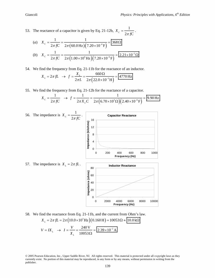
56. The impedance is 1
2CX
fC.
57. The impedance is 2LX fL .
58. We find the reactance from Eq. 21-11b, and the current from Ohm’s law. 3
2
2 2 10.0 10 Hz 0.160 H 10053 10.0 k
240 V 2.39 10 A
10053
L
L
L
X fL
VV IX I
X
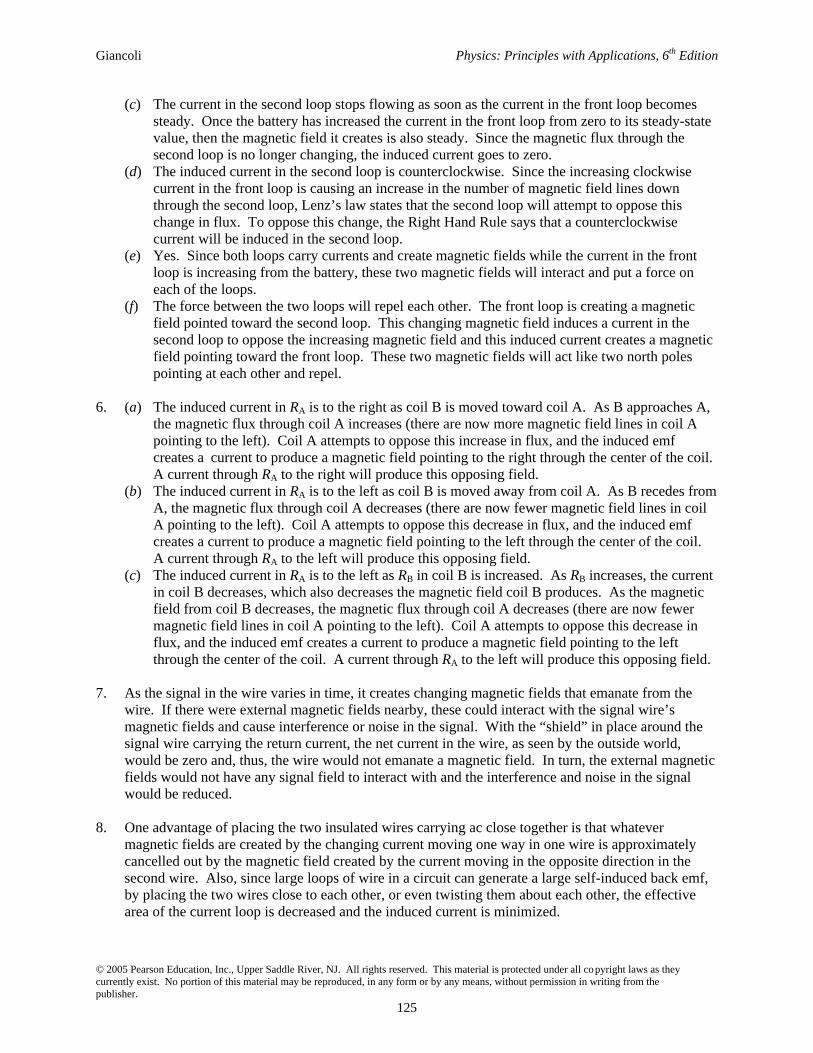
Capacitor Reactance
0
4
8
12
16
0 200 400 600 800 1000Frequency (Hz)
Imp
edan
ce (
kilo
hm
s)
Inductor Reactance
0
20
40
60
80
0 2000 4000 6000 8000 10000Frequency (Hz)
Imp
edan
ce (
oh
ms)
Chapter 21 Electromagnetic Induction and Faraday’s Law
© 2005 Pearson Education, Inc., Upper Saddle River, NJ. All rights reserved. This material is protected under all copyright laws as they currently exist. No portion of this material may be reproduced, in any form or by any means, without permission in writing from the publisher.
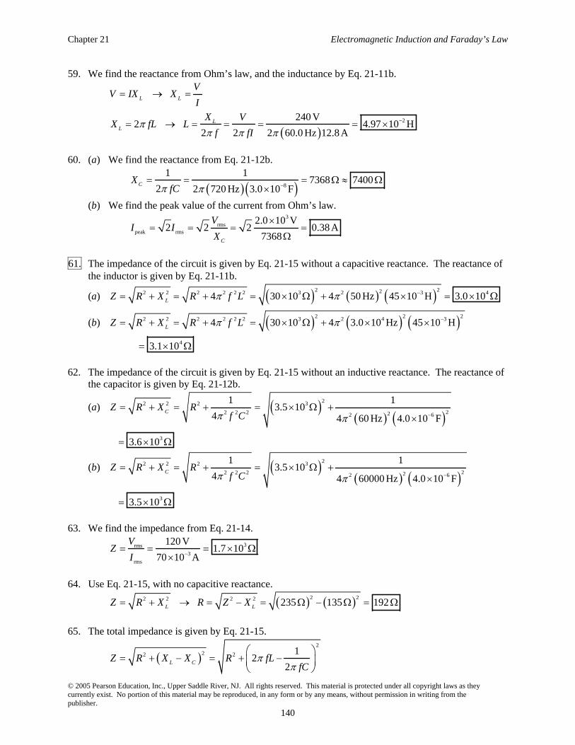
140
59. We find the reactance from Ohm’s law, and the inductance by Eq. 21-11b.
2 240 V2 4.97 10 H
2 2 2 60.0 Hz 12.8 A
L L
LL
VV IX X
I
X VX fL L
f fI
60. (a) We find the reactance from Eq. 21-12b.
8
1 17368 7400
2 2 720 Hz 3.0 10 FCX
fC
(b) We find the peak value of the current from Ohm’s law. 3
rmspeak rms
2.0 10 V2 2 2 0.38 A
7368C
VI I
X
61. The impedance of the circuit is given by Eq. 21-15 without a capacitive reactance. The reactance of the inductor is given by Eq. 21-11b.
(a) 2 222 2 2 2 2 2 3 2 3 44 30 10 4 50 Hz 45 10 H 3.0 10LZ R X R f L
(b) 2 2 22 2 2 2 2 2 3 2 4 34 30 10 4 3.0 10 Hz 45 10 HLZ R X R f L
4 3.1 10
62. The impedance of the circuit is given by Eq. 21-15 without an inductive reactance. The reactance of the capacitor is given by Eq. 21-12b.
(a) 22 2 2 3
22 2 2 22 6
1 13.5 10
4 4 60 Hz 4.0 10 FCZ R X R
f C
3 3.6 10
(b) 22 2 2 3
22 2 2 22 6
1 13.5 10
4 4 60000 Hz 4.0 10 FCZ R X R
f C
3 3.5 10
63. We find the impedance from Eq. 21-14.
3rms
3
rms
120 V1.7 10
70 10 A
VZ
I
64. Use Eq. 21-15, with no capacitive reactance. 2 22 2 2 2
235 135 192L LZ R X R Z X
65. The total impedance is given by Eq. 21-15. 2
22 2 12
2L CZ R X X R fL
fC
Giancoli Physics: Principles with Applications, 6th Edition
© 2005 Pearson Education, Inc., Upper Saddle River, NJ. All rights reserved. This material is protected under all copyright laws as they currently exist. No portion of this material may be reproduced, in any form or by any means, without permission in writing from the publisher.
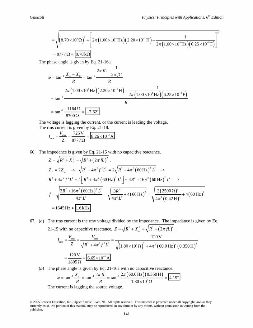
141
2
23 4 2
4 9
1 8.70 10 2 1.00 10 Hz 2.20 10 H
2 1.00 10 Hz 6.25 10 F
8777 8.78 k
The phase angle is given by Eq. 21-16a.
1 1
4 2
4 9
1
1 o
12
2tan tan
12 1.00 10 Hz 2.20 10 H
2 1.00 10 Hz 6.25 10 F
tan
1164 tan 7.62
8700
L C
fLX X fC
R R
R
The voltage is lagging the current, or the current is leading the voltage. The rms current is given by Eq. 21-18.
2rmsrms
725 V8.26 10 A
Z 8777
VI
66. The impedance is given by Eq. 21-15 with no capacitive reactance. 22 2 2 2LZ R X R fL .
22 2 2 2 2 2 2
60
2 22 2 2 2 2 2 2 2 2 2
2 22 2 2 22 2
22 2 2 2 2
2 4 2 4 60 Hz
4 4 4 60 Hz 4 16 60 Hz
3 16 60 Hz 3 250034 60 Hz 4 60 Hz
4 4 4 0.42 H
1645 Hz 1.6 kHz
fZ Z R f L R L
R f L R L R L
R L Rf
L L
67. (a) The rms current is the rmv voltage divided by the impedance. The impedance is given by Eq.
21-15 with no capacitive reactance, 22 2 2 2LZ R X R fL .
rms rmsrms
2 2 2 2 2 2 23 2
2
120 V
4 1.80 10 4 60.0 Hz 0.350 H
120 V 6.65 10 A
1805
V VI
Z R f L
(b) The phase angle is given by Eq. 21-16a with no capacitive reactance.
1 1 1 o
3
2 60.0 Hz 0.350 H2tan tan tan 4.19
1.80 10LX fL
R R
The current is lagging the source voltage.
Chapter 21 Electromagnetic Induction and Faraday’s Law
© 2005 Pearson Education, Inc., Upper Saddle River, NJ. All rights reserved. This material is protected under all copyright laws as they currently exist. No portion of this material may be reproduced, in any form or by any means, without permission in writing from the publisher.
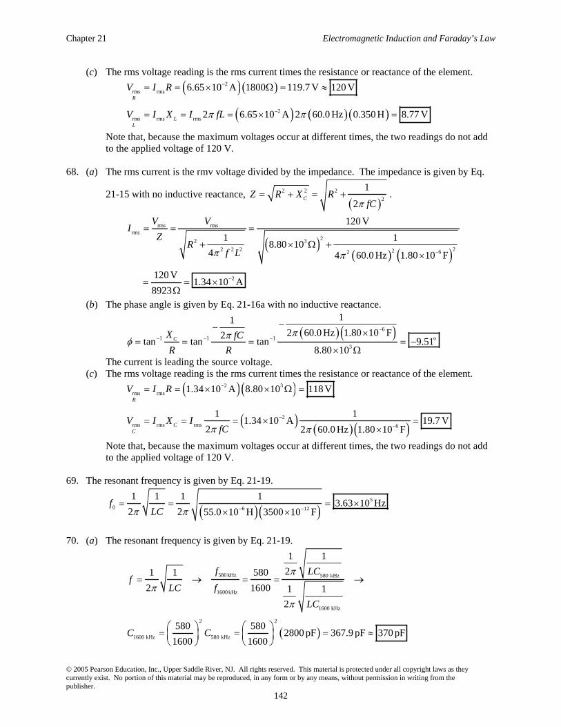
142
(c) The rms voltage reading is the rms current times the resistance or reactance of the element. 2
rms rms
2
rms rms rms
6.65 10 A 1800 119.7 V 120 V
2 6.65 10 A 2 60.0 Hz 0.350 H 8.77 V
R
LL
V I R
V I X I fL
Note that, because the maximum voltages occur at different times, the two readings do not add to the applied voltage of 120 V.
68. (a) The rms current is the rmv voltage divided by the impedance. The impedance is given by Eq.
21-15 with no inductive reactance, 2 2 2
2
1
2CZ R X R
fC.
rms rmsrms
22 3
22 2 2 22 6
2
120 V
1 18.80 10
4 4 60.0 Hz 1.80 10 F
120 V 1.34 10 A
8923
V VI
ZR
f L
(b) The phase angle is given by Eq. 21-16a with no inductive reactance.
6
1 1 1 o
3
112 60.0 Hz 1.80 10 F2
tan tan tan 9.518.80 10
CX fC
R R
The current is leading the source voltage. (c) The rms voltage reading is the rms current times the resistance or reactance of the element.
2 3
rms rms
2
rms rms rms 6
1.34 10 A 8.80 10 118 V
1 11.34 10 A 19.7 V
2 2 60.0 Hz 1.80 10 F
R
CC
V I R
V I X IfC
Note that, because the maximum voltages occur at different times, the two readings do not add to the applied voltage of 120 V.
69. The resonant frequency is given by Eq. 21-19.
5
0 6 12
1 1 1 13.63 10 Hz
2 2 55.0 10 H 3500 10 Ff
LC
70. (a) The resonant frequency is given by Eq. 21-19.
580 kHz 580 kHz
1600kHz
1600 kHz
2 2
1600 kHz 580 kHz
1 1
21 1 580
2 1600 1 1
2
580 5802800 pF 367.9 pF 370 pF
1600 1600
f LCf
LC f
LC
C C
Giancoli Physics: Principles with Applications, 6th Edition
© 2005 Pearson Education, Inc., Upper Saddle River, NJ. All rights reserved. This material is protected under all copyright laws as they currently exist. No portion of this material may be reproduced, in any form or by any means, without permission in writing from the publisher.
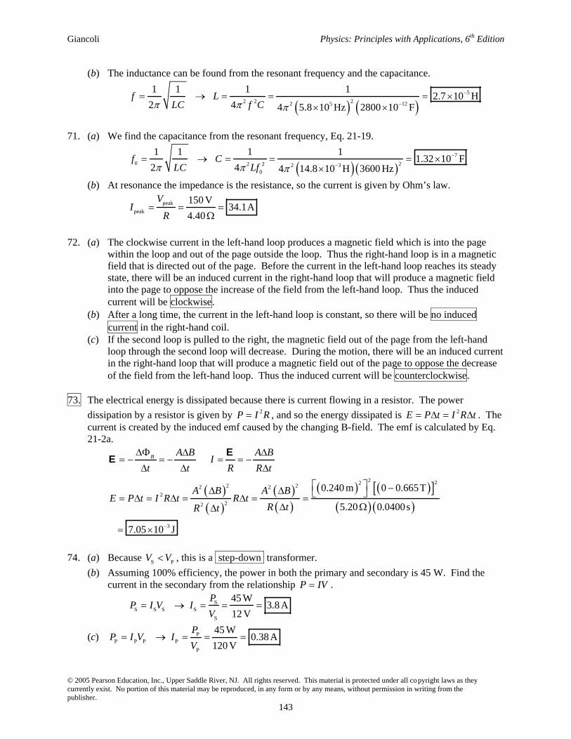
143
(b) The inductance can be found from the resonant frequency and the capacitance.
5
22 2 2 5 12
1 1 1 1
2.7 10 H
2 4 4 5.8 10 Hz 2800 10 Ff L
LC f C
71. (a) We find the capacitance from the resonant frequency, Eq. 21-19.
7
0 22 2 2 30
1 1 1 1
1.32 10 F2 4 4 14.8 10 H 3600 Hz
f CLC Lf
(b) At resonance the impedance is the resistance, so the current is given by Ohm’s law.
peak
peak
150 V34.1A
4.40
VI
R
72. (a) The clockwise current in the left-hand loop produces a magnetic field which is into the page within the loop and out of the page outside the loop. Thus the right-hand loop is in a magnetic field that is directed out of the page. Before the current in the left-hand loop reaches its steady state, there will be an induced current in the right-hand loop that will produce a magnetic field into the page to oppose the increase of the field from the left-hand loop. Thus the induced current will be clockwise.
(b) After a long time, the current in the left-hand loop is constant, so there will be no induced current in the right-hand coil.
(c) If the second loop is pulled to the right, the magnetic field out of the page from the left-hand loop through the second loop will decrease. During the motion, there will be an induced current in the right-hand loop that will produce a magnetic field out of the page to oppose the decrease of the field from the left-hand loop. Thus the induced current will be counterclockwise.
73. The electrical energy is dissipated because there is current flowing in a resistor. The power
dissipation by a resistor is given by 2P I R , and so the energy dissipated is 2E P t I R t . The current is created by the induced emf caused by the changing B-field. The emf is calculated by Eq. 21-2a.
2 222 22 22
22
3
0.240 m 0 0.665T
5.20 0.0400s
7.05 10 J
B A B A BI
t t R R t
A B A BE P t I R t R t
R tR t
EE
74. (a) Because S PV V , this is a step-down transformer.
(b) Assuming 100% efficiency, the power in both the primary and secondary is 45 W. Find the current in the secondary from the relationship P IV .
SS S S S
S
45 W
3.8 A12 V
PP I V I
V
(c) PP P P P
P
45 W
0.38 A120 V
PP I V I
V
Chapter 21 Electromagnetic Induction and Faraday’s Law
© 2005 Pearson Education, Inc., Upper Saddle River, NJ. All rights reserved. This material is protected under all copyright laws as they currently exist. No portion of this material may be reproduced, in any form or by any means, without permission in writing from the publisher.
144
(d) Find the resistance of the bulb from Ohm’s law. The bulb is in the secondary circuit.
SS S
S
12 V
3.2
3.75 A
VV I R R
I
75. Because there are perfect transformers, the power loss is due to resistive heating in the transmission
lines. Since the town requires 50 MW, the power at the generating plant must be 50 MW
0.98550.761
MW. Thus the power lost in the transmission is 0.761 MW. This can be used to determine the current in the transmission lines.
62 0.761 10 W
179.6 A2 118 km 0.10 km
PP I R I
R
To produce 50.761 MW of power at 179.6 A requires the following voltage. 6
550.761 10 W2.83 10 V 280 kV
179.6 A
PV
I
76. (a) From the efficiency of the transformer, we have S P0.80P P . Use this to calculate the current
in the primary.
SS P P P P
P
75 W0.80 0.80 0.8523A 0.85 A
0.80 0.80 110 V
PP P I V I
V
(b) The voltage in both the primary and secondary is proportional to the number of turns in the respective coil. The secondary voltage is calculated from the secondary power and resistance
since 2P V R .
P P P
S S S S
110V8.2
75W 2.4
N V V
N V P R
77. (a) The voltage drop across the lines is due to the resistance.
out in 42000V 740A 2 0.80 40816V 41kVV V IR
(b) The power input is given by in inP IV .
7 7
in in 740A 42000V 3.108 10 W 3.1 10 WP IV
(c) The power loss in the lines is due to the current in the resistive wires. 22 5 5
loss 740A 1.60 8.76 10 W 8.8 10 WP I R
(d) The power output is given by out outP IV .
7 7
out out 740A 40816V 3.020 10 W 3.0 10 WP IV .
This could also be found by subtracting the power lost from the input power. 7 5 7 7
out in loss 3.108 10 W 8.76 10 W 3.020 10 W 3.0 10 WP P P
Giancoli Physics: Principles with Applications, 6th Edition
© 2005 Pearson Education, Inc., Upper Saddle River, NJ. All rights reserved. This material is protected under all copyright laws as they currently exist. No portion of this material may be reproduced, in any form or by any means, without permission in writing from the publisher.
145
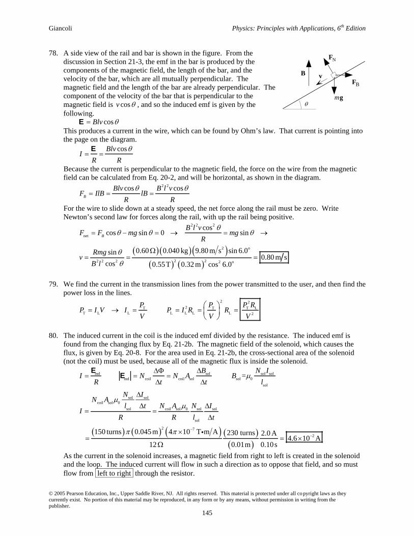
78. A side view of the rail and bar is shown in the figure. From the discussion in Section 21-3, the emf in the bar is produced by the components of the magnetic field, the length of the bar, and the velocity of the bar, which are all mutually perpendicular. The magnetic field and the length of the bar are already perpendicular. The component of the velocity of the bar that is perpendicular to the magnetic field is cosv , and so the induced emf is given by the following.
cosBlvE
This produces a current in the wire, which can be found by Ohm’s law. That current is pointing into the page on the diagram.
cosBlvI
R R
E
Because the current is perpendicular to the magnetic field, the force on the wire from the magnetic field can be calculated from Eq. 20-2, and will be horizontal, as shown in the diagram.
2 2cos cosB
Blv B l vF IlB lB
R R
For the wire to slide down at a steady speed, the net force along the rail must be zero. Write Newton’s second law for forces along the rail, with up the rail being positive.
2 2 2
net
2 o
2 22 2 2 2 o
coscos sin 0 sin
0.60 0.040 kg 9.80 m s sin 6.0sin0.80 m s
cos 0.55T 0.32 m cos 6.0
B
B l vF F mg mg
R
Rmgv
B l
79. We find the current in the transmission lines from the power transmitted to the user, and then find the power loss in the lines.
2 22T T T L
T L L L L L L 2
P P P RP I V I P I R R
V V V
80. The induced current in the coil is the induced emf divided by the resistance. The induced emf is found from the changing flux by Eq. 21-2b. The magnetic field of the solenoid, which causes the flux, is given by Eq. 20-8. For the area used in Eq. 21-2b, the cross-sectional area of the solenoid (not the coil) must be used, because all of the magnetic flux is inside the solenoid.
ind sol sol solind coil coil sol sol 0
sol
sol solcoil sol 0
sol coil sol 0 sol sol
sol
2 7
2
=
150 turns 0.045 m 4 10 T m A 230 turns 2.0 A
4.6 10 A12 0.01m 0.10s
B N II N N A B
R t t l
N IN A
l t N A N II
R R l t
EE
As the current in the solenoid increases, a magnetic field from right to left is created in the solenoid and the loop. The induced current will flow in such a direction as to oppose that field, and so must flow from left to right through the resistor.
B
FB
FN
mgs
v
Chapter 21 Electromagnetic Induction and Faraday’s Law
© 2005 Pearson Education, Inc., Upper Saddle River, NJ. All rights reserved. This material is protected under all copyright laws as they currently exist. No portion of this material may be reproduced, in any form or by any means, without permission in writing from the publisher.
146
81. Putting an inductor in series with the device will protect it from sudden surges in current. The growth of current in an LR circuit is given is section 21-11.
max1 1tR L tR LVI e I e
R
The maximum current is 55 mA, and the current is to have a value of 7.5 mA after a time of 120 microseconds. Use this data to solve for the inductance.
max
max
4
max
1 1
1.2 10 sec 1500.1228 H 0.12 H in series
7.5 mAln 1ln 1
55 mA
tR L tR L II I e e
I
tRL
I
I
82. The emf is related to the flux change by Eq. 21-2b. The flux change is caused by the changing magnetic field.
22
120 V
390T s25 6.25 10 m
B A B BN N
t t t NA
EE
83. We find the peak emf from Eq. 21-5. 22
peak 155 0.200 T 2 rad rev 120 rev s 6.60 10 m 102 VNB AE
84. (a) The electric field energy density is given by Eq. 17-11, and the magnetic field energy density is given by Eq. 21-10.
2 12 2 2 41 102 2
4 3 4 3
226 3 6 31 1
2 2 70
6 39
4 3
8.85 10 C N m 1.0 10 V m
4.425 10 J m 4.4 10 J m
2.0T1.592 10 J m 1.6 10 J m
4 10 T m A
1.592 10 J m3.6 10
4.425 10 J m
E
B
B
E
u E
Bu
u
u
The energy density in the magnetic field is 3.6 billion times greater than the energy density in the electric field.
(b) Set the two densities equal and solve for the magnitude of the electric field. 2
21 102 2
0
8
12 2 2 70 0
2.0T6.0 10 V m
8.85 10 C N m 4 10 T m A
E B
Bu E u
BE
85. The impedance is found from Eq. 21-14, and then the inductance is found from Eq. 21-11b.
0 0
0 0
220 V
2 0.10 H2 2 2 60.0 Hz 5.8 A
LL L
V VXZ X X fL L
I f fI
Giancoli Physics: Principles with Applications, 6th Edition
© 2005 Pearson Education, Inc., Upper Saddle River, NJ. All rights reserved. This material is protected under all copyright laws as they currently exist. No portion of this material may be reproduced, in any form or by any means, without permission in writing from the publisher.
147
86. For the current and voltage to be in phase, the net reactance of the capacitor and inductor must be zero, which means that the circuit is at resonance. Thus Eq. 21-19 applies.
7
0 22 2 20
1 1 1 1
1.05 10 F
2 4 4 0.130 H 1360 Hzf C
LC Lf
87. The resistance of the coil is found from the dc current via Ohm’s law.
dcdc dc
dc
36 V
14.4 142.5 A
VV I R R
I
The impedance of the coil is found from the ac current by Eq. 21-14, and then the inductance can be found from the impedance by Eq. 21-15a.
2 2 2 2 2 2acac ac
ac
2
22ac
2 2ac
22 2 2
4
120 V14.4
3.8 A7.455 10 H 7.5 10 H
4 4 60 Hz
L
VV ZI Z R X R f L
I
VR
IL
f
88. (a) The current is found from the voltage and impedance. The impedance is given by Eq. 21-15. 2
22 2
2
2
6
rmsrms
12
2
1
2.0 2 60 Hz 0.135 H 81.762 60 Hz 20 10 F
45 V0.55 A
81.76
L CZ R X X R fLfC
VI
Z
(b) Use Eq. 21-16a to find the phase angle.
1 1
6
1 1 o
12
2tan tan
12 60 Hz 0.135 H
2 60 Hz 20 10 F 81.7
tan tan 892.0 2.0
L C
fLX X fC
R R
89. (a) From the text of the problem, the Q factor is the ratio of the voltage across the capacitor or inductor to the voltage across the resistor, at resonance. The resonant frequency is given by Eq. 21-19.
res res
res
1 12
2 12LL
R
LI X f LV LLCQ
V I R R R R C
Chapter 21 Electromagnetic Induction and Faraday’s Law
© 2005 Pearson Education, Inc., Upper Saddle River, NJ. All rights reserved. This material is protected under all copyright laws as they currently exist. No portion of this material may be reproduced, in any form or by any means, without permission in writing from the publisher.
148
(b) Find the inductance from the resonant frequency, and the resistance from the Q factor.
res
6 6
22 2 2 8 6res
62
8
1 1
2
1 12.533 10 H 2.5 10 H
4 4 1.0 10 F 1.0 10 Hz
1 1 1 2.533 10 H 2.9 10
550 1.0 10 F
fLC
LCf
L LQ R
R C Q C


![L 29 Electricity and Magnetism [6] Review Faraday’s Law of Electromagnetic Induction induced currents electric generator eddy currents electromagnetic.](https://static.fdocuments.us/doc/165x107/56649e765503460f94b7766d/l-29-electricity-and-magnetism-6-review-faradays-law-of-electromagnetic.jpg)