Chapter 21apetrov/PHY2140/Lecture20.pdf · P = i. 2. R where i is the ... R Also applies to the...
60
Chapter 21 Chapter 21 Alternating Current Circuits Alternating Current Circuits and Electromagnetic Waves and Electromagnetic Waves
Transcript of Chapter 21apetrov/PHY2140/Lecture20.pdf · P = i. 2. R where i is the ... R Also applies to the...
Chapter 21Chapter 21
Alternating Current Circuits Alternating Current Circuits and Electromagnetic Wavesand Electromagnetic Waves
AC CircuitAC Circuit
An AC circuit consists of a combination of An AC circuit consists of a combination of circuit elements and an AC generator or circuit elements and an AC generator or sourcesourceThe output of an AC generator is sinusoidal The output of an AC generator is sinusoidal and varies with time according to the and varies with time according to the following equationfollowing equation∆∆v = v = ∆∆VVmaxmax sin 2sin 2ππƒƒtt
∆∆v is the instantaneous voltagev is the instantaneous voltage∆∆VVmaxmax is the maximum voltage of the generatoris the maximum voltage of the generatorƒƒ is the frequency at which the voltage changes, in Hzis the frequency at which the voltage changes, in Hz
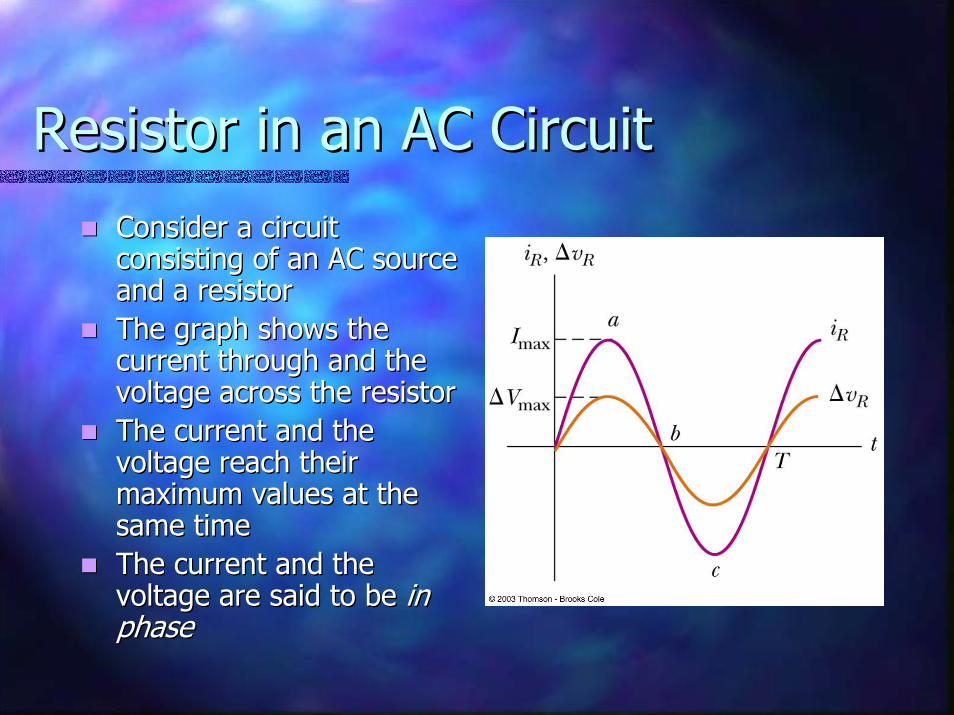
Resistor in an AC CircuitResistor in an AC CircuitConsider a circuit Consider a circuit consisting of an AC source consisting of an AC source and a resistorand a resistorThe graph shows the The graph shows the current through and the current through and the voltage across the resistorvoltage across the resistorThe current and the The current and the voltage reach their voltage reach their maximum values at the maximum values at the same timesame timeThe current and the The current and the voltage are said to be voltage are said to be in in phasephase

More About Resistors in an AC More About Resistors in an AC CircuitCircuit
The direction of the current has no effect on The direction of the current has no effect on the behavior of the resistorthe behavior of the resistorThe rate at which electrical energy is The rate at which electrical energy is dissipated in the circuit is given bydissipated in the circuit is given by
P = iP = i22 RRwhere i is the where i is the instantaneous currentinstantaneous currentthe heating effect produced by an AC current with a the heating effect produced by an AC current with a maximum value of Imaximum value of Imaxmax is not the same as that of a DC is not the same as that of a DC current of the same valuecurrent of the same valueThe maximum current occurs for a small amount of timeThe maximum current occurs for a small amount of time
rms Current and Voltagerms Current and Voltage
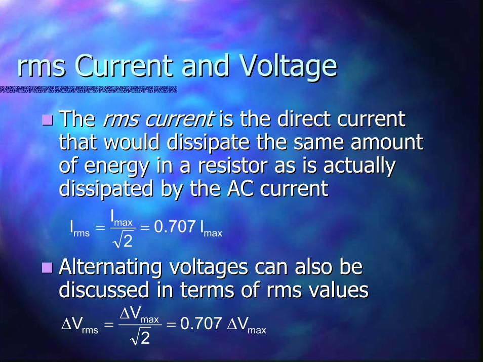
The The rms currentrms current is the direct current is the direct current that would dissipate the same amount that would dissipate the same amount of energy in a resistor as is actually of energy in a resistor as is actually dissipated by the AC currentdissipated by the AC current
Alternating voltages can also be Alternating voltages can also be discussed in terms of rms valuesdiscussed in terms of rms values
maxmax
rms I707.02
II ==
maxmax
rms V707.02VV ∆=
∆=∆

Ohm’s Law in an AC CircuitOhm’s Law in an AC Circuit
rms values will be used when discussing rms values will be used when discussing AC currents and voltagesAC currents and voltages
AC ammeters and voltmeters are designed AC ammeters and voltmeters are designed to read rms valuesto read rms valuesMany of the equations will be in the same Many of the equations will be in the same form as in DC circuitsform as in DC circuits
Ohm’s Law for a resistor, R, in an AC Ohm’s Law for a resistor, R, in an AC circuitcircuit∆∆VVrmsrms = I= Irmsrms RR
Also applies to the maximum values of v and iAlso applies to the maximum values of v and i

Capacitors in an AC CircuitCapacitors in an AC Circuit
Consider a circuit containing a capacitor and Consider a circuit containing a capacitor and an AC sourcean AC sourceThe current starts out at a large value and The current starts out at a large value and charges the plates of the capacitorcharges the plates of the capacitor
There is initially no resistance to hinder the flow of There is initially no resistance to hinder the flow of the current while the plates are not chargedthe current while the plates are not charged
As the charge on the plates increases, the As the charge on the plates increases, the voltage across the plates increases and the voltage across the plates increases and the current flowing in the circuit decreasescurrent flowing in the circuit decreases
More About Capacitors in an More About Capacitors in an AC CircuitAC Circuit
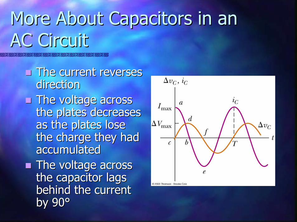
The current reverses The current reverses directiondirectionThe voltage across The voltage across the plates decreases the plates decreases as the plates lose as the plates lose the charge they had the charge they had accumulatedaccumulatedThe voltage across The voltage across the capacitor lags the capacitor lags behind the current behind the current by 90°by 90°

Capacitive Reactance and Capacitive Reactance and Ohm’s LawOhm’s Law
The impeding effect of a capacitor on the The impeding effect of a capacitor on the current in an AC circuit is called the current in an AC circuit is called the capacitive capacitive reactancereactance and is given byand is given by
When ƒ is in Hz and C is in F, XWhen ƒ is in Hz and C is in F, XCC will be in ohmswill be in ohms
Ohm’s Law for a capacitor in an AC circuitOhm’s Law for a capacitor in an AC circuit∆∆VVrmsrms = I= Irmsrms XXC
Cƒ21XC π
=
C

Inductors in an AC CircuitInductors in an AC Circuit
Consider an AC circuit Consider an AC circuit with a source and an with a source and an inductorinductorThe current in the The current in the circuit is impeded by circuit is impeded by the back emf of the the back emf of the inductorinductorThe voltage across the The voltage across the inductor always leads inductor always leads the current by 90°the current by 90°

Inductive Reactance and Inductive Reactance and Ohm’s LawOhm’s Law
The effective resistance of a coil in an The effective resistance of a coil in an AC circuit is called its AC circuit is called its inductive inductive reactancereactance and is given byand is given by
XXLL = 2= 2ππƒƒLLWhen ƒ is in Hz and L is in H, XWhen ƒ is in Hz and L is in H, XLL will be in will be in ohmsohms
Ohm’s Law for the inductorOhm’s Law for the inductor∆∆VVrmsrms = I= Irmsrms XXLL

The RLC Series CircuitThe RLC Series Circuit
The resistor, The resistor, inductor, and inductor, and capacitor can be capacitor can be combined in a circuitcombined in a circuitThe current in the The current in the circuit is the same at circuit is the same at any time and varies any time and varies sinusoidally with sinusoidally with timetime
Current and Voltage Current and Voltage Relationships in an RLC CircuitRelationships in an RLC Circuit
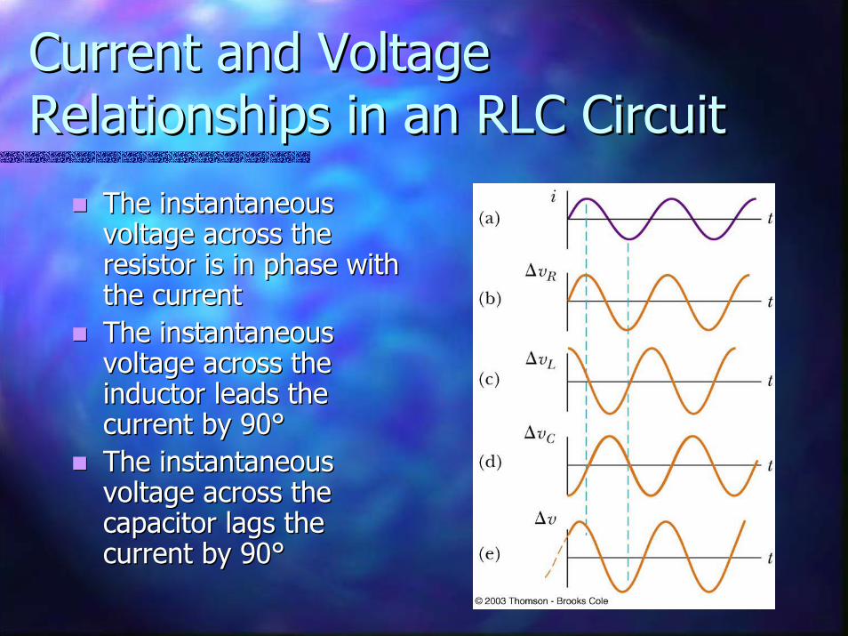
The instantaneous The instantaneous voltage across the voltage across the resistor is in phase with resistor is in phase with the currentthe currentThe instantaneous The instantaneous voltage across the voltage across the inductor leads the inductor leads the current by 90°current by 90°The instantaneous The instantaneous voltage across the voltage across the capacitor lags the capacitor lags the current by 90°current by 90°

Phasor DiagramsPhasor Diagrams
To account for the To account for the different phases of the different phases of the voltage drops, vector voltage drops, vector techniques are usedtechniques are usedRepresent the voltage Represent the voltage across each element as across each element as a rotating vector, called a rotating vector, called a a phasorphasorThe diagram is called a The diagram is called a phasor diagramphasor diagram

Phasor Diagram for RLC Phasor Diagram for RLC Series CircuitSeries Circuit
The voltage across the The voltage across the resistor is on the +x resistor is on the +x axis since it is in phase axis since it is in phase with the currentwith the currentThe voltage across the The voltage across the inductor is on the +y inductor is on the +y since it leads the since it leads the current by 90°current by 90°The voltage across the The voltage across the capacitor is on the capacitor is on the ––y y axis since it lags behind axis since it lags behind the current by 90°the current by 90°

Phasor Diagram, contPhasor Diagram, cont
The phasors are The phasors are added as vectors to added as vectors to account for the account for the phase differences in phase differences in the voltagesthe voltages∆∆VVLL and and ∆∆VVCC are on are on the same line and so the same line and so the net y component the net y component is is ∆∆VVL L -- ∆∆VVCC
∆∆VVmaxmax From the Phasor From the Phasor DiagramDiagram
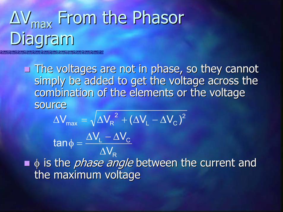
The voltages are not in phase, so they cannot The voltages are not in phase, so they cannot simply be added to get the voltage across the simply be added to get the voltage across the combination of the elements or the voltage combination of the elements or the voltage sourcesource
φφ is the is the phase anglephase angle between the current and between the current and the maximum voltagethe maximum voltage
R
CL
2CL
2Rmax
VVVtan
)VV(VV
∆∆−∆
=φ
∆−∆+∆=∆
Impedance of a CircuitImpedance of a Circuit
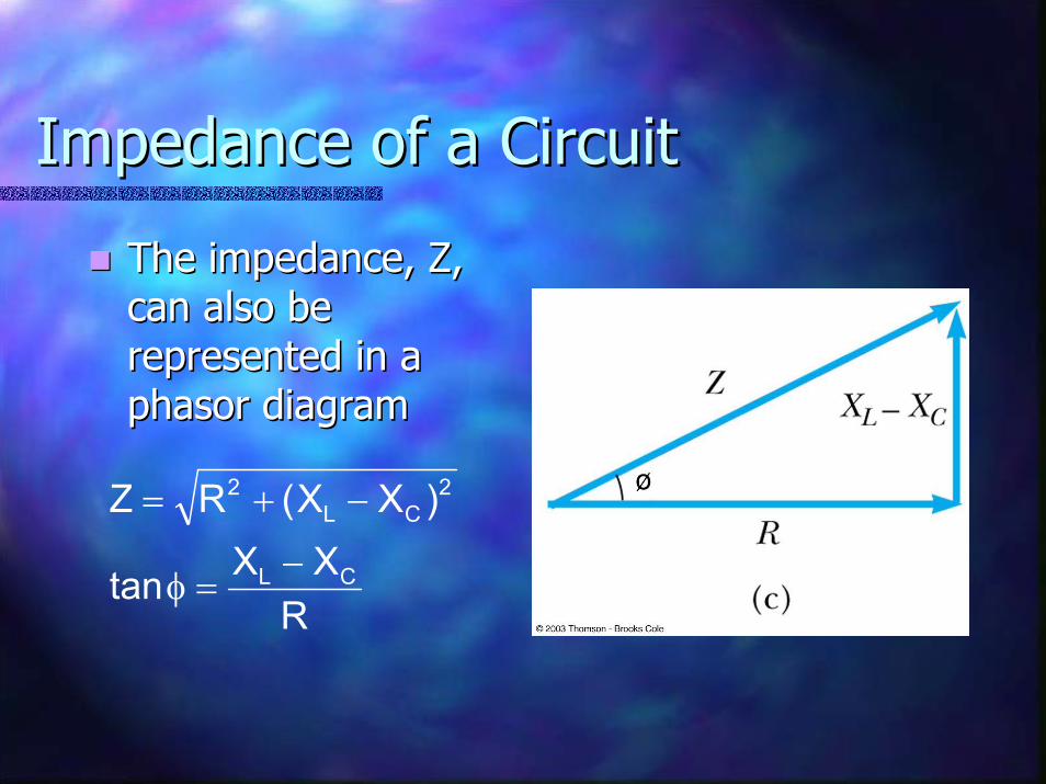
The impedance, Z, The impedance, Z, can also be can also be represented in a represented in a phasor diagramphasor diagram
RXXtan
)XX(RZ
CL
2CL
2
−=φ
−+=

Impedance and Ohm’s LawImpedance and Ohm’s Law
Ohm’s Law can be applied to the Ohm’s Law can be applied to the impedanceimpedance∆∆VVmaxmax = I= Imaxmax ZZ

Summary of Circuit Elements, Summary of Circuit Elements, Impedance and Phase AnglesImpedance and Phase Angles

Problem Solving for AC Problem Solving for AC CircuitsCircuits
Calculate as many unknown quantities Calculate as many unknown quantities as possibleas possible
For example, find XFor example, find XLL and Xand XCC
Be careful of units Be careful of units ---- use F, H, use F, H, ΩΩApply Ohm’s Law to the portion of the Apply Ohm’s Law to the portion of the circuit that is of interestcircuit that is of interestDetermine all the unknowns asked for Determine all the unknowns asked for in the problemin the problem

Power in an AC CircuitPower in an AC Circuit
No power losses are associated with No power losses are associated with capacitors and pure inductors in an AC circuitcapacitors and pure inductors in an AC circuit
In a capacitor, during oneIn a capacitor, during one--half of a cycle energy is half of a cycle energy is stored and during the other half the energy is stored and during the other half the energy is returned to the circuitreturned to the circuitIn an inductor, the source does work against the In an inductor, the source does work against the back emf of the inductor and energy is stored in back emf of the inductor and energy is stored in the inductor, but when the current begins to the inductor, but when the current begins to decrease in the circuit, the energy is returned to decrease in the circuit, the energy is returned to the circuitthe circuit

Power in an AC Circuit, contPower in an AC Circuit, cont
The average power delivered by the The average power delivered by the generator is converted to internal generator is converted to internal energy in the resistorenergy in the resistor
PPavav = I= Irmsrms∆∆VVRR = = IIrmsrms∆∆VVrmsrms cos cos φφcos cos φφ is called the is called the power factorpower factor of the of the circuitcircuit
Phase shifts can be used to maximize Phase shifts can be used to maximize power outputspower outputs
Resonance in an AC CircuitResonance in an AC Circuit
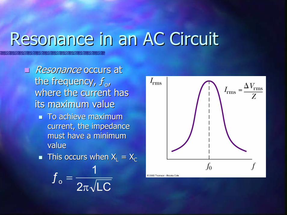
ResonanceResonance occurs at occurs at the frequency, ƒthe frequency, ƒoo, , where the current has where the current has its maximum valueits maximum value
To achieve maximum To achieve maximum current, the impedance current, the impedance must have a minimum must have a minimum valuevalueThis occurs when XThis occurs when XLL = X= XCC
LC21ƒo
π=

Resonance, contResonance, cont
Theoretically, if R = 0 the current would be Theoretically, if R = 0 the current would be infinite at resonanceinfinite at resonance
Real circuits always have some resistanceReal circuits always have some resistance
Tuning a radioTuning a radioA varying capacitor changes the resonance frequency A varying capacitor changes the resonance frequency of the tuning circuit in your radio to match the station of the tuning circuit in your radio to match the station to be receivedto be received
Metal DetectorMetal DetectorThe portal is an inductor, and the frequency is set to a The portal is an inductor, and the frequency is set to a condition with no metal presentcondition with no metal presentWhen metal is present, it changes the effective When metal is present, it changes the effective inductance, which changes the current which is inductance, which changes the current which is detected and an alarm soundsdetected and an alarm sounds
TransformersTransformers
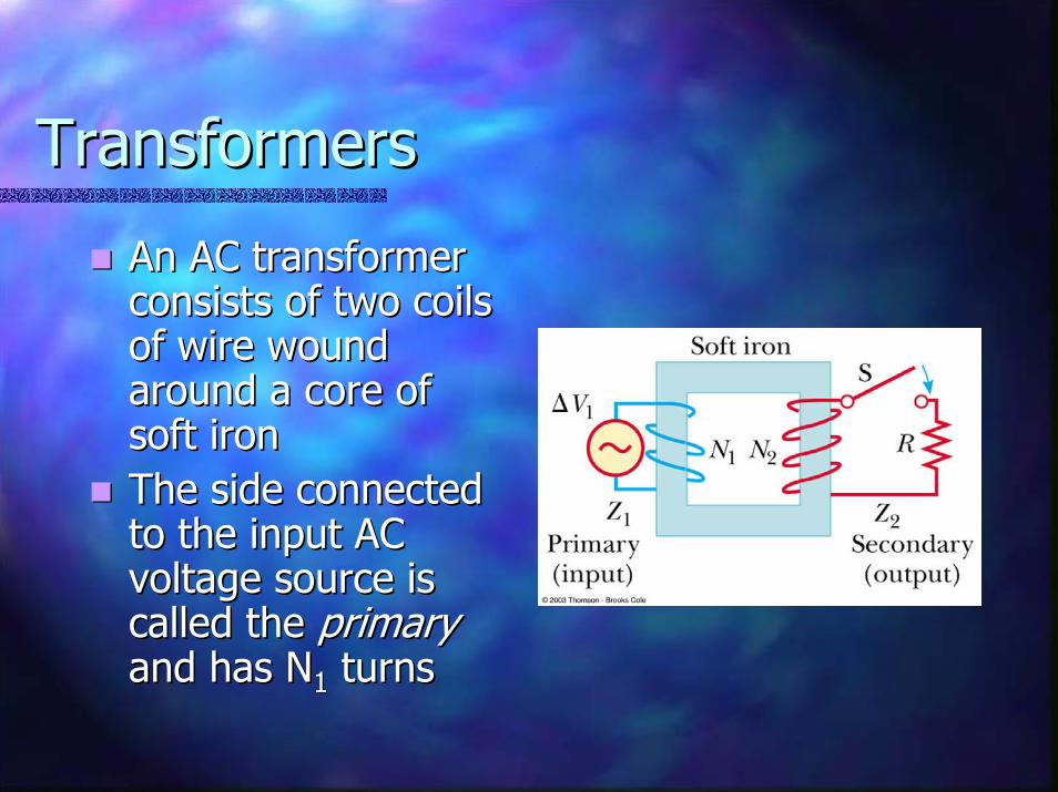
An AC transformer An AC transformer consists of two coils consists of two coils of wire wound of wire wound around a core of around a core of soft ironsoft ironThe side connected The side connected to the input AC to the input AC voltage source is voltage source is called the called the primaryprimaryand has Nand has N11 turnsturns
Transformers, 2Transformers, 2
The other side, called the The other side, called the secondarysecondary, is , is connected to a resistor and has Nconnected to a resistor and has N22 turnsturnsThe core is used to increase the The core is used to increase the magnetic flux and to provide a medium magnetic flux and to provide a medium for the flux to pass from one coil to the for the flux to pass from one coil to the otherotherThe rate of change of the flux is the The rate of change of the flux is the same for both coilssame for both coils

Transformers, 3Transformers, 3
The voltages are related byThe voltages are related by
When NWhen N22 > N> N11, the transformer is , the transformer is referred to as a referred to as a step upstep up transformertransformerWhen NWhen N22 < N< N11, the transformer is , the transformer is referred to as a referred to as a step down step down transformer
11
22 V
NNV ∆=∆
transformer
Transformer, finalTransformer, final
The power input into the primary equals The power input into the primary equals the power output at the secondarythe power output at the secondary
II11∆∆VV11 = I= I22∆∆VV22You don’t get something for nothingYou don’t get something for nothing
This assumes an ideal transformerThis assumes an ideal transformerIn real transformers, power efficiencies In real transformers, power efficiencies typically range from 90% to 99%typically range from 90% to 99%
Electrical Power TransmissionElectrical Power Transmission
When transmitting electric power over long When transmitting electric power over long distances, it is most economical to use high distances, it is most economical to use high voltage and low currentvoltage and low current
Minimizes IMinimizes I22R power lossesR power losses
In practice, voltage is stepped up to about In practice, voltage is stepped up to about 230 000 V at the generating station and 230 000 V at the generating station and stepped down to 20 000 V at the distribution stepped down to 20 000 V at the distribution station and finally to 120 V at the customer’s station and finally to 120 V at the customer’s utility poleutility pole
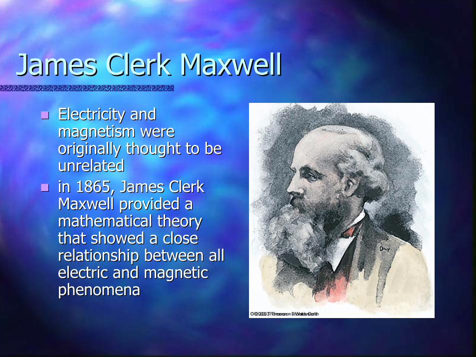
James Clerk MaxwellJames Clerk Maxwell
Electricity and Electricity and magnetism were magnetism were originally thought to be originally thought to be unrelatedunrelatedin 1865, James Clerk in 1865, James Clerk Maxwell provided a Maxwell provided a mathematical theory mathematical theory that showed a close that showed a close relationship between all relationship between all electric and magnetic electric and magnetic phenomenaphenomena

Maxwell’s Starting PointsMaxwell’s Starting Points
Electric field lines originate on positive Electric field lines originate on positive charges and terminate on negative chargescharges and terminate on negative chargesMagnetic field lines always form closed loops Magnetic field lines always form closed loops –– they do not begin or end anywherethey do not begin or end anywhereA varying magnetic field induces an emf and A varying magnetic field induces an emf and hence an electric field (Faraday’s Law)hence an electric field (Faraday’s Law)Magnetic fields are generated by moving Magnetic fields are generated by moving charges or currents (Ampcharges or currents (Ampèèrere’’s Law)s Law)

Maxwell’s PredictionsMaxwell’s Predictions
Maxwell used these starting points and a Maxwell used these starting points and a corresponding mathematical framework to prove corresponding mathematical framework to prove that that electric and magnetic fields play symmetric electric and magnetic fields play symmetric roles in natureroles in natureHe hypothesized that a changing electric field He hypothesized that a changing electric field would produce a magnetic fieldwould produce a magnetic fieldMaxwell calculated the speed of light to be 3x10Maxwell calculated the speed of light to be 3x1088
m/sm/sHe concluded that visible light and all other He concluded that visible light and all other electromagnetic waves consist of fluctuating electromagnetic waves consist of fluctuating electric and magnetic fields, with each varying electric and magnetic fields, with each varying field inducing the otherfield inducing the other
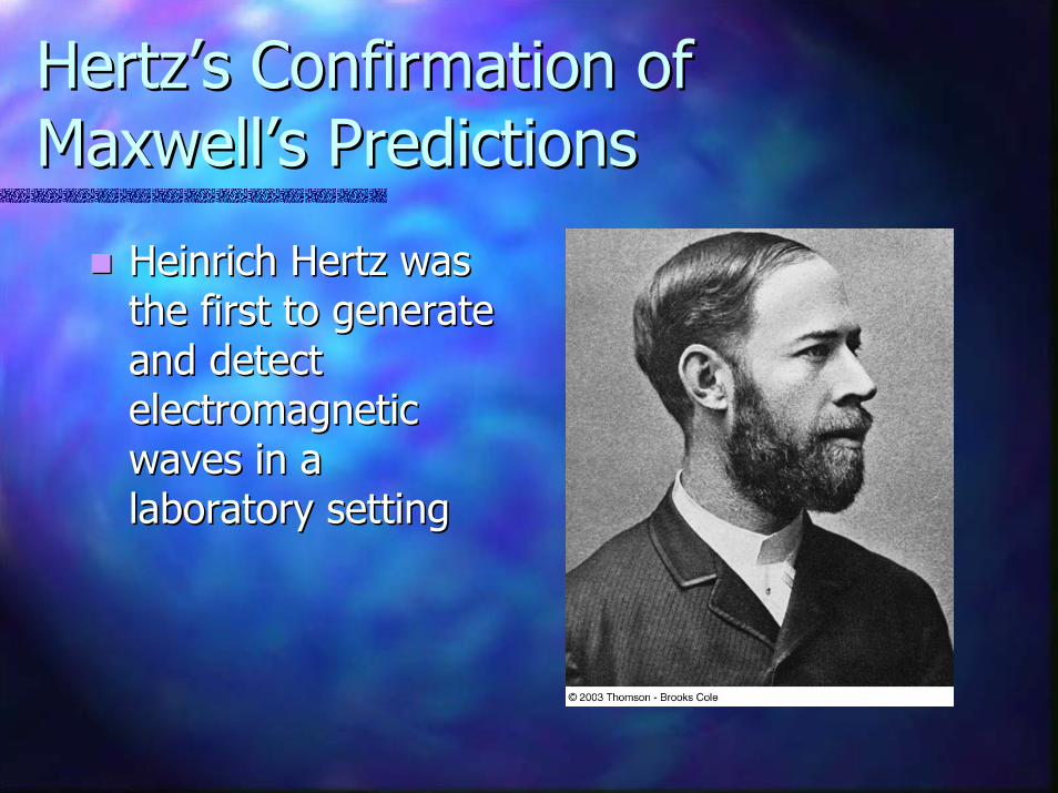
Hertz’s Confirmation of Hertz’s Confirmation of Maxwell’s PredictionsMaxwell’s Predictions
Heinrich Hertz was Heinrich Hertz was the first to generate the first to generate and detect and detect electromagnetic electromagnetic waves in a waves in a laboratory settinglaboratory setting

Hertz’s Basic LC CircuitHertz’s Basic LC Circuit
When the switch is When the switch is closed, oscillations closed, oscillations occur in the current and occur in the current and in the charge on the in the charge on the capacitorcapacitorWhen the capacitor is When the capacitor is fully charged, the total fully charged, the total energy of the circuit is energy of the circuit is stored in the electric stored in the electric field of the capacitorfield of the capacitor
At this time, the current At this time, the current is zero and no energy is is zero and no energy is stored in the inductorstored in the inductor
LC Circuit, contLC Circuit, cont
As the capacitor discharges, the energy stored in As the capacitor discharges, the energy stored in the electric field decreasesthe electric field decreasesAt the same time, the current increases and the At the same time, the current increases and the energy stored in the magnetic field increasesenergy stored in the magnetic field increasesWhen the capacitor is fully discharged, there is When the capacitor is fully discharged, there is no energy stored in its electric fieldno energy stored in its electric field
The current is at a maximum and all the energy is The current is at a maximum and all the energy is stored in the magnetic field in the inductorstored in the magnetic field in the inductor
The process repeats in the opposite directionThe process repeats in the opposite directionThere is a continuous transfer of energy between There is a continuous transfer of energy between the inductor and the capacitorthe inductor and the capacitor
Hertz’s Experimental Hertz’s Experimental ApparatusApparatus
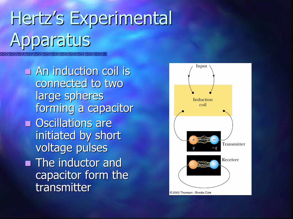
An induction coil is An induction coil is connected to two connected to two large spheres large spheres forming a capacitorforming a capacitorOscillations are Oscillations are initiated by short initiated by short voltage pulsesvoltage pulsesThe inductor and The inductor and capacitor form the capacitor form the transmittertransmitter

Hertz’s ExperimentHertz’s Experiment
Several meters away from the Several meters away from the transmitter is the receivertransmitter is the receiver
This consisted of a single loop of wire This consisted of a single loop of wire connected to two spheresconnected to two spheresIt had its own inductance and capacitanceIt had its own inductance and capacitance
When the resonance frequencies of the When the resonance frequencies of the transmitter and receiver matched, transmitter and receiver matched, energy transfer occurred between themenergy transfer occurred between them

Hertz’s ConclusionsHertz’s Conclusions
Hertz hypothesized the energy transfer Hertz hypothesized the energy transfer was in the form of waveswas in the form of waves
These are now known to be These are now known to be electromagnetic waveselectromagnetic waves
Hertz confirmed Maxwell’s theory by Hertz confirmed Maxwell’s theory by showing the waves existed and had all showing the waves existed and had all the properties of light wavesthe properties of light waves
They had different frequencies and They had different frequencies and wavelengthswavelengths
Hertz’s Measure of the Speed Hertz’s Measure of the Speed of the Wavesof the Waves
Hertz measured the speed of the waves from Hertz measured the speed of the waves from the transmitterthe transmitter
He used the waves to form an interference pattern He used the waves to form an interference pattern and calculated the wavelengthand calculated the wavelengthFrom v = f From v = f λλ, v was found, v was foundv was very close to 3 x 10v was very close to 3 x 1088 m/s, the known speed m/s, the known speed of lightof light
This provided evidence in support of This provided evidence in support of Maxwell’s theoryMaxwell’s theory
Electromagnetic Waves Electromagnetic Waves Produced by an AntennaProduced by an Antenna
When a charged particle undergoes an When a charged particle undergoes an acceleration, it must radiate energyacceleration, it must radiate energy
If currents in an ac circuit change rapidly, some If currents in an ac circuit change rapidly, some energy is lost in the form of em wavesenergy is lost in the form of em wavesEM waves are radiated by any circuit carrying EM waves are radiated by any circuit carrying alternating currentalternating current
An alternating voltage applied to the wires of An alternating voltage applied to the wires of an antenna forces the electric charge in the an antenna forces the electric charge in the antenna to oscillateantenna to oscillate

EM Waves by an Antenna, EM Waves by an Antenna, contcont
Two rods are connected to an ac source, charges oscillate Two rods are connected to an ac source, charges oscillate between the rods (a)between the rods (a)As oscillations continue, the rods become less charged, As oscillations continue, the rods become less charged, the field near the charges decreases and the field the field near the charges decreases and the field produced at t = 0 moves away from the rod (b)produced at t = 0 moves away from the rod (b)The charges and field reverse (c)The charges and field reverse (c)The oscillations continue (d)The oscillations continue (d)
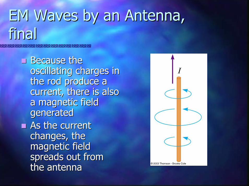
EM Waves by an Antenna, EM Waves by an Antenna, finalfinal
Because the Because the oscillating charges in oscillating charges in the rod produce a the rod produce a current, there is also current, there is also a magnetic field a magnetic field generatedgeneratedAs the current As the current changes, the changes, the magnetic field magnetic field spreads out from spreads out from the antennathe antenna
Charges and Fields, SummaryCharges and Fields, Summary
Stationary charges produce only electric Stationary charges produce only electric fieldsfieldsCharges in uniform motion (constant Charges in uniform motion (constant velocity) produce electric and magnetic velocity) produce electric and magnetic fieldsfieldsCharges that are accelerated produce Charges that are accelerated produce electric and magnetic fields and electric and magnetic fields and electromagnetic waveselectromagnetic waves

Electromagnetic Waves, Electromagnetic Waves, SummarySummary
A changing magnetic field produces an A changing magnetic field produces an electric fieldelectric fieldA changing electric field produces a A changing electric field produces a magnetic fieldmagnetic fieldThese fields are These fields are in phasein phase
At any point, both fields reach their At any point, both fields reach their maximum value at the same timemaximum value at the same time
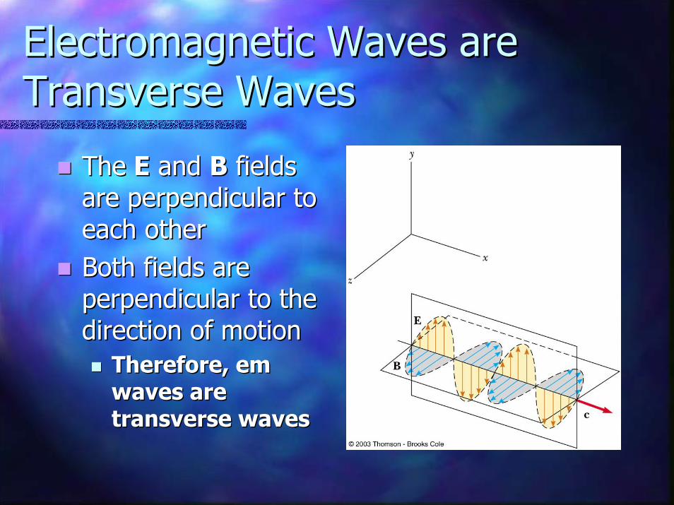
Electromagnetic Waves are Electromagnetic Waves are Transverse WavesTransverse Waves
TheThe EE and and BB fields fields are perpendicular to are perpendicular to each othereach otherBoth fields are Both fields are perpendicular to the perpendicular to the direction of motiondirection of motion
Therefore, em Therefore, em waves are waves are transverse wavestransverse waves

Properties of EM WavesProperties of EM Waves
Electromagnetic waves are transverse wavesElectromagnetic waves are transverse wavesElectromagnetic waves travel at the speed of Electromagnetic waves travel at the speed of lightlight
Because em waves travel at a speed that is Because em waves travel at a speed that is precisely the speed of light, precisely the speed of light, light is an light is an electromagnetic waveelectromagnetic wave
oo
1cεµ
=
Properties of EM Waves, 2Properties of EM Waves, 2
The ratio of the electric field to the magnetic The ratio of the electric field to the magnetic field is equal to the speed of lightfield is equal to the speed of light
Electromagnetic waves carry energy as they Electromagnetic waves carry energy as they travel through space, and this energy can be travel through space, and this energy can be transferred to objects placed in their path
BEc =
transferred to objects placed in their path
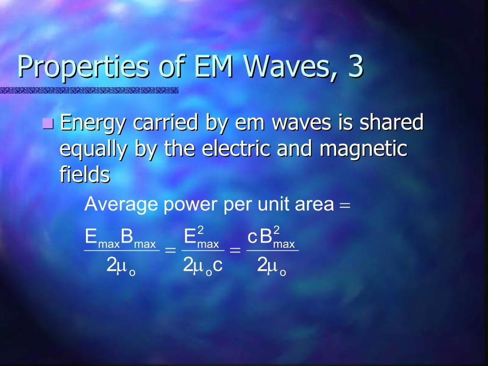
Properties of EM Waves, 3Properties of EM Waves, 3
Energy carried by em waves is shared Energy carried by em waves is shared equally by the electric and magnetic equally by the electric and magnetic fieldsfields
o
2max
o
2max
o
maxmax
2Bc
c2E
2BE
areaunitperpowerAverage
µ=
µ=
µ
=

Properties of EM Waves, finalProperties of EM Waves, final
Electromagnetic waves transport linear Electromagnetic waves transport linear momentum as well as energymomentum as well as energy
For complete absorption of energy U, For complete absorption of energy U, p=U/cp=U/cFor complete reflection of energy U, For complete reflection of energy U, p=(2U)/cp=(2U)/c
Radiation pressures can be determined Radiation pressures can be determined experimentallyexperimentally
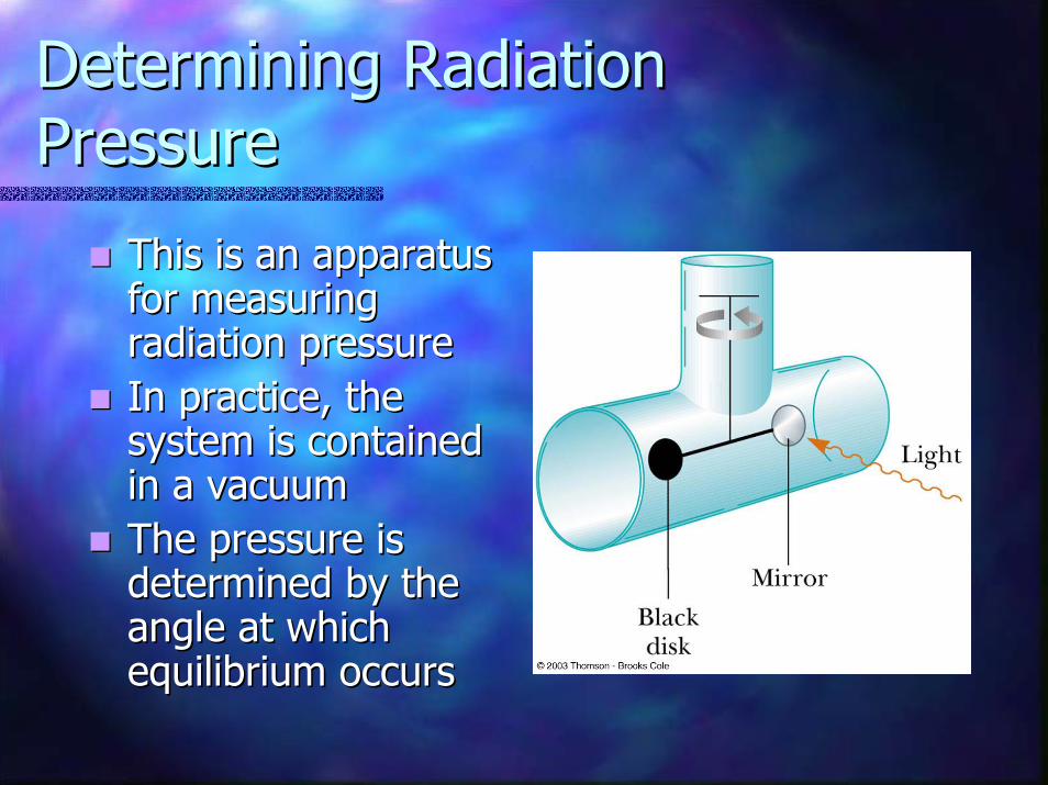
Determining Radiation Determining Radiation PressurePressure
This is an apparatus This is an apparatus for measuring for measuring radiation pressureradiation pressureIn practice, the In practice, the system is contained system is contained in a vacuumin a vacuumThe pressure is The pressure is determined by the determined by the angle at which angle at which equilibrium occursequilibrium occurs
The Spectrum of EM WavesThe Spectrum of EM Waves
Forms of electromagnetic waves exist Forms of electromagnetic waves exist that are distinguished by their that are distinguished by their frequencies and wavelengthsfrequencies and wavelengths
c = ƒc = ƒλλWavelengths for visible light range from Wavelengths for visible light range from 400 nm to 700 nm400 nm to 700 nmThere is no sharp division between one There is no sharp division between one kind of em wave and the nextkind of em wave and the next

The EMThe EMSpectrumSpectrum
Note the overlap Note the overlap between types of between types of waveswavesVisible light is a Visible light is a small portion of small portion of the spectrumthe spectrumTypes are Types are distinguished by distinguished by frequency or frequency or wavelengthwavelength
Notes on The EM SpectrumNotes on The EM Spectrum
Radio WavesRadio WavesUsed in radio and television communication Used in radio and television communication systemssystems
MicrowavesMicrowavesWavelengths from about 1 mm to 30 cmWavelengths from about 1 mm to 30 cmWell suited for radar systemsWell suited for radar systemsMicrowave ovens are an applicationMicrowave ovens are an application

Notes on the EM Spectrum, 2Notes on the EM Spectrum, 2
Infrared wavesInfrared wavesIncorrectly called “heat waves”Incorrectly called “heat waves”Produced by hot objects and moleculesProduced by hot objects and moleculesReadily absorbed by most materialsReadily absorbed by most materials
Visible lightVisible lightPart of the spectrum detected by the Part of the spectrum detected by the human eyehuman eyeMost sensitive at about 560 nm (yellowMost sensitive at about 560 nm (yellow--green)green)

Notes on the EM Spectrum, 3Notes on the EM Spectrum, 3
Ultraviolet lightUltraviolet lightCovers about 400 nm to 0.6 nmCovers about 400 nm to 0.6 nmSun is an important source of uv lightSun is an important source of uv lightMost uv light from the sun is absorbed in the Most uv light from the sun is absorbed in the stratosphere by ozonestratosphere by ozone
XX--raysraysMost common source is acceleration of highMost common source is acceleration of high--energy electrons striking a metal targetenergy electrons striking a metal targetUsed as a diagnostic tool in medicineUsed as a diagnostic tool in medicine

Notes on the EM Spectrum, Notes on the EM Spectrum, finalfinal
Gamma raysGamma raysEmitted by radioactive nucleiEmitted by radioactive nucleiHighly penetrating and cause serious Highly penetrating and cause serious damage when absorbed by living tissuedamage when absorbed by living tissue
Looking at objects in different portions Looking at objects in different portions of the spectrum can produce different of the spectrum can produce different informationinformation

Doppler Effect and EM WavesDoppler Effect and EM Waves
A Doppler Effect occurs for em waves, but A Doppler Effect occurs for em waves, but differs from that of sound wavesdiffers from that of sound waves
For sound waves, motion relative to a medium is For sound waves, motion relative to a medium is most importantmost important
For light waves, the medium plays no role since the light For light waves, the medium plays no role since the light waves do not require a medium for propagationwaves do not require a medium for propagation
The speed of sound depends on its frame of The speed of sound depends on its frame of referencereference
The speed of em waves is the same in all coordinate The speed of em waves is the same in all coordinate systems that are at rest or moving with a constant systems that are at rest or moving with a constant velocity with respect to each othervelocity with respect to each other
Doppler Equation for EM Doppler Equation for EM WavesWaves
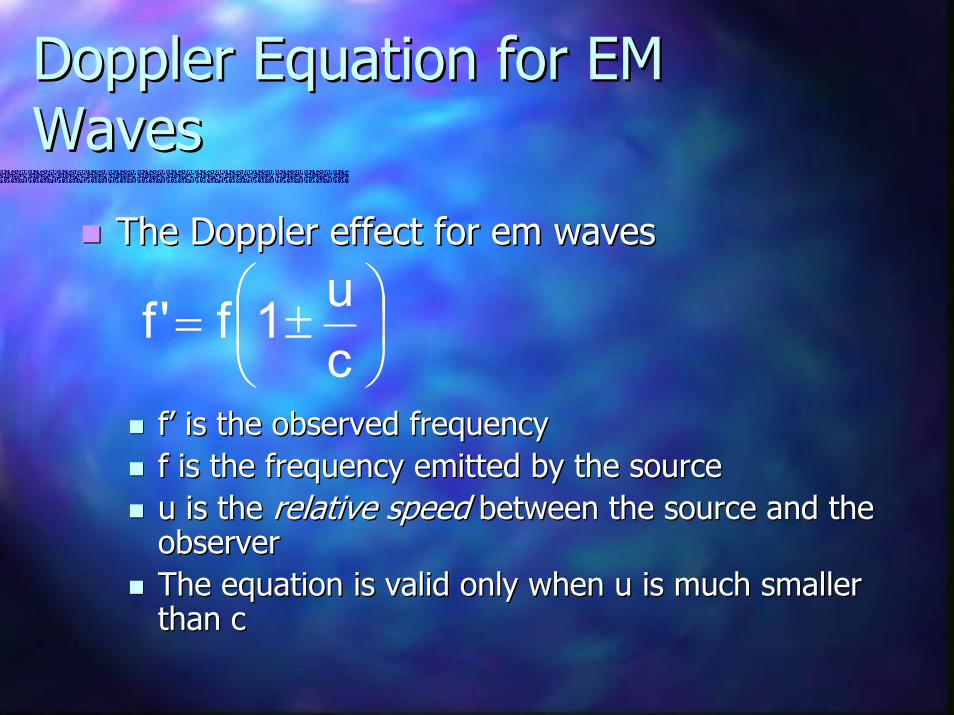
The Doppler effect for em wavesThe Doppler effect for em waves
f’ is the observed frequencyf’ is the observed frequencyf is the frequency emitted by the sourcef is the frequency emitted by the sourceu is the u is the relative speedrelative speed between the source and the between the source and the observerobserverThe equation is valid only when u is much smaller The equation is valid only when u is much smaller than c
±=
cu1f'f
than c

Doppler Equation, contDoppler Equation, cont
The positive sign is used when the object The positive sign is used when the object and source are moving and source are moving towardtoward each othereach otherThe negative sign is used when the object The negative sign is used when the object and source are moving and source are moving away fromaway from each each otherotherAstronomers refer to a Astronomers refer to a red shiftred shift when when objects are moving away from the earth objects are moving away from the earth since the wavelengths are shifted toward since the wavelengths are shifted toward the red end of the spectrumthe red end of the spectrum


![[PPT]PowerPoint Presentation - Hypersensitivitymcb.berkeley.edu/.../Lecture20/Lecture20_files/Lecture20.ppt · Web viewHypersensitivity Robert Beatty MCB150 TYPE I Hypersensitivity](https://static.fdocuments.us/doc/165x107/5aa9eb4b7f8b9a7c188d726c/pptpowerpoint-presentation-viewhypersensitivity-robert-beatty-mcb150-type-i.jpg)