
Chapter 1 VSAT new pictures · Quick CSS VSAT 1.2M System Assembly and Disassembly Procedures F-1...
148
Draft Combat Service Support Very Small Aperture Terminal (CSS VSAT) 1.2 Meter (1.2M) Operational Reference Guide (ORG) UNOFFICIAL DOCUMENT April 2007 ver5.2 DRAFT
Transcript of Chapter 1 VSAT new pictures · Quick CSS VSAT 1.2M System Assembly and Disassembly Procedures F-1...

Draft Combat Service Support
Very Small Aperture Terminal (CSS VSAT)
1.2 Meter (1.2M)
Operational Reference Guide (ORG)
UNOFFICIAL DOCUMENT
April 2007 ver5.2 DRAFT

ALERT Compliance message to all potential users of the CSS VSAT 1.2M System. Installing or placing any software on CSS VSAT terminal components, including the satellite terminal’s integral laptop, is strictly prohibited. Only software provided by or approved by the Program Manager, CSS SATCOM may be installed on CSS VSAT components. CSS VSAT components are constantly monitored. Any terminal components found to contain unauthorized software will result in the satellite terminal being immediately disconnected from the CSS SATCOM Network which will result in the loss of connectivity for all users.

i
5 SAFETY STEPS TO FOLLOW IF SOMEONE IS THE VICTIM OF ELECTRICAL SHOCK: 1. DO NOT TRY TO TOUCH, PULL OR GRAB THE
INDIVIDUAL. 2. IF POSSIBLE, TURN OFF THE ELECTRICAL POWER. 3. IF YOU CANNOT TURN OFF THE ELECTRICAL POWER,
PULL, PUSH, OR LIFT THE PERSON TO SAFETY USING A DRY WOODEN POLE OR OTHER NONCONDUCTING, INSULATED MATERIAL.
4. AFTER THE INJURED PERSON IS FREE OF CONTACT
WITH THE SOURCE OF ELECTRICAL SHOCK, MOVE THE PERSON TO A SAFE LOCATION AND IMMEDIATELY ADMINISTER FIRST AID.
5. SEND FOR HELP AS SOON AS POSSIBLE.

ii
NOTICE: This manual contains three types of notices: Warnings, Cautions, and Notes. An explanation of each follows:
WARNING
Warning notices alert users to the possibility of immediate death or personal injury. Although damage to equipment may occur, the major concern is the probability of death or permanent injury if the warning notice is ignored.
CAUTION
Caution notices alert users to the possibility of damage to equipment from failure to follow procedures.
NOTE
A Note provides general information concerning operations and procedures.
WARNINGS
• DO NOT stand in front of or place any portion of your body between the Feed Boom and the Antenna Reflector. It may cause serious injury to the eyes or any part of the body due to radiation.
• Keep hands clear of the Cable Reel when extending or retrieving cables.
CAUTIONS
• The CSS VSAT 1.2M System has an approximate weight of 540 pounds. • Use safe lift and carry procedures when handling the cases. Each case may require up to a
two-person lift and carry. • Keep cases closed and latched when not accessing equipment to minimize the probability of
injury or snagging clothing. • Never connect or disconnect cables when the power is on. • Connect and disconnect the power cord(s) using the plugs instead of pulling on the cord. • Provide strain relief (slack) for cables.
NOTES • Inventory and inspect all cases. • Refer to Appendix E for an Equipment Checklist for the CSS VSAT 1.2M Systems. • Annotate any discrepancies or shortages on DA Form 2404 (Appendix G).

iii
TABLE OF CONTENTS Chapter/Paragraph Page Chapter I
CSS VSAT 1.2M System General Information
1-1
1.1 Introduction 1-1 1.2 CSS VSAT 1.2M System Equipment 1-2 1.3 CSS VSAT 1.2M System Evolution 1-2 1.4 CSS VSAT 1.2M System Purpose 1-3 1.5 Satellite Networks 1-3 1.6 CSS VSAT 1.2M System Security 1-5 1.6.1 CSS VSAT 1.2M System Information Assurance Manager (IAM) 1-5
1.6.2 CSS VSAT 1.2M System Information Assurance Security Officer (IASO) 1-6
1.6.3 CSS VSAT 1.2M System Administrator (SA) 1-6 1.6.4 CSS VSAT 1.2M System User Responsibilities 1-8 Chapter II CSS VSAT 1.2M System Operations 2-1 2.1 CSS VSAT 1.2M System Operation Procedures 2-1 2.2 System Setup 2-1 2.3 Establish CSS VSAT 1.2M System Communications 2-19 2.4 ViewSAT Application Overview 2-20 2.5 Basic Troubleshooting Procedures 2-34 2.5.1 Troubleshoot the CSS VSAT 1.2M System 2-34 Chapter III CSS VSAT 1.2M System Interface Devices 3-1 3.1 CSS VSAT 1.2M System Interface Devices 3-1 3.2 CSS VSAT 1.2M System Interface Procedures to the CBM 3-2
3.3 CSS VSAT 1.2M System VoIP Phone Models 7911G/7912G Overview 3-3
3.4 Unpack and Identify the VoIP Phone Case 3-4 3.5 VoIP Operations 3-6 3.5.1 Changing VoIP Phones IP Address 3-6
3.5.2 CSS VSAT 1.2M System Connection Procedures to a VoIP Phone 3-8
3.5.3 Place a Call over the Network 3-10 3.6 CSS VSAT 1.2M System VoIP Phone Basic Troubleshooting 3-12

iv
Chapter/Paragraph Page Chapter IV CSS VSAT 1.2M System Maintenance 4-1 4.1 System Maintenance 4-1 4.1.1 General 4-1 4.1.2 Maintenance Concept 4-1 4.1.3 CSS VSAT 1.2M System Line Replaceable Units (LRUs) 4-2
4.1.4 Basic Field Level and Contract Logistics Support (CLS) Maintenance Procedures 4-2
4.1.5 CSS VSAT 1.2M System Help Desk 4-4
4.1.6 Manufacturer – Regional Support Center (RSC) – Sustainment Maintenance 4-5
4.2 Preventive Maintenance Checks and Services (PMCS) Procedures 4-7
4.2.1 Routine Checks 4-7
4.2.2 CSS VSAT Preventive Maintenance Checks and Services (PMCS) Checklist 4-9
Chapter V Prepare CSS VSAT 1.2M System for Movement and Storage 5-1 5.1 Sending the System Offline 5-1 5.2 Performing a SOFT System Shutdown 5-2 5.3 Packing and Preparing for Movement and Storage Procedures. 5-5 Appendix A Glossary and Acronyms A-1 Appendix B Basic Troubleshooting Procedures B-1 Appendix C Major Equipment List and System Specifications C-1 Appendix D Articles D-1 Appendix E CSS VSAT 1.2M System Equipment Checklist E-1
Appendix F Quick CSS VSAT 1.2M System Assembly and Disassembly Procedures F-1
Appendix G DA Form 2404 G-1 Appendix H Galaxy XR KU North America Downlink Beam H-1 Galaxy XR KU Europe/ Middle East Downlink Beam H-2 Galaxy XR KU Central Asia Downlink Beam H-3 Key to Global Satellite Coverage Guide H-4 Global Satellite Coverage Guide H-5 Appendix I CSS VSAT 1.2M System Block Diagram Architecture I-1

v
LIST OF FIGURES FIGURE NUMBER
NAME
PAGE
1-1 CSS VSAT 1.2M System Cases and Assembled 1.2M System 1-2 1-2 CSS VSAT 1.2M 1-3 1-3 CSS Hub Station 1-3 1-4 Satellite Network Communications CONUS/OCONUS 1-4 2-1 CSS VSAT 1.2M System Cases 2-1 2-2 Hemisphere Diagram 2-2 2-3 Antenna Pedestal Case 2-2 2-4 Antenna Pedestal Case - Interior 2-3 2-5 Antenna Pedestal 2-3 2-6 Control Box 2-3 2-7 Outriggers and Hand Crank 2-3 2-8 Outrigger Connections 2-4 2-9 Outriggers Installed 2-4 2-10 RF Equipment Case 2-4 2-11 RF Equipment Case – Interior 2-5 2-12 Antenna Feed Horn Assembly 2-5 2-13 LNB’s 2-5 2-14 Cable Reel 2-6 2-15 Compass/Inclinometer 2-6 2-16 Indoor Equipment Case 2-7 2-17 Indoor Equipment Case with Pouch 2-8 2-18 Indoor Equipment Case with Hanging Covers 2-8 2-19 Indoor Equipment Case Front View 2-8 2-20 Indoor Equipment Case Rear Panel 2-8 2-21 Ground Fault Interrupter (GFI) 2-9 2-22 Brake Force Adjustment and Cable Reel 2-9 2-23 Control Box Cable Connections 2-10 2-24 Indoor Equipment Case Cable Connections 2-10 2-25 Brake Force Adjustment Lever - Lock 2-10 2-26 AC Circuit Breaker 2-11 2-27 Antenna and RF Power Switches 2-11 2-28 Control Box - 1 2-11 2-29 Control Box - 2 2-11

vi
FIGURE NUMBER
NAME
PAGE
2-30 Reflector Case 2-12 2-31 Antenna Reflector Dish 2-12 2-32 Antenna Feed Boom 2-13 2-33 Reflector Case - Interior 2-13 2-34 Antenna Feed Support Struts 2-13 2-35 Antenna Reflector Connections 2-13 2-36 Antenna Reflector on a Clean Flat Surface 2-14 2-37 Antenna Feed Boom and Antenna Feed Support Struts 2-14 2-38 Antenna Feed Boom Connection to the Antenna Reflector 2-14 2-39 Antenna Feed Support Struts Connected to Antenna Feed Boom 2-15 2-40 Antenna Feed Support Struts Connected to the Antenna Reflector 2-15 2-41 Antenna Feed Horn Assembly 2-15 2-42 Feed Horn Assembly Connection 2-16 2-43 Feed Horn Polarization Adjustment Screws 2-16 2-44 Cross Polarization BUC 2-16 2-45 CO Polarization BUC 2-16 2-46 Cable Connections 2-17 2-47 Assembled Antenna Reflector Placed on the Mounting Wedge 2-17 2-48 ¼ Turn Fasteners 2-17 2-49 BUC, LNB, GPS and Compass Cable Connections 2-17 2-50 Antenna Reflector Cable Support Rod 2-18 2-51 CSS VSAT 1.2M System Assembled 2-18 2-52 CSS VSAT 1.2M 2-19 2-53 Control Box 2-19 2-54 Indoor Equipment Case Front Panel 2-19 2-55 ViewSAT Icon 2-20 2-56 System Login Window 2-20 2-57 NetModem Lights and Initialization Window 2-21 2-58 ViewSAT Setup Screen 2-21 2-59 ViewSAT Status Tree Box 2-22 2-60 ViewSAT Reference Box 2-23 2-61 ViewSAT Traffic Meter Box 2-23 2-62 ViewSAT System Commands Box 2-24 2-63 ViewSAT Current Status Box 2-24 2-64 ViewSAT Startup Progress Box 2-25

vii
FIGURE NUMBER
NAME
PAGE
2-65 ViewSAT Operation Tab View 2-25 2-66 ViewSAT Control Buttons 2-26 2-67 ViewSAT Modem Information Box 2-26 2-68 ViewSAT SSPA Information Box 2-26 2-69 ViewSAT ACU Information Box 2-27 2-70 ViewSAT Satellite Position Lookup 2-27 2-71 ViewSAT IP Subnet Address Box 2-27 2-72 IP Address Schematics 2-28 2-73 ViewSAT Setup Tab 2-29 2-74 Confirm Startup Window 2-29 2-75 Assemble Hardware Window 2-29 2-76 LNB Selection Window 2-29 2-77 Reset ACU Frequency Window 2-30 2-78 ViewSAT Startup Screen 2-30 2-79 Setup Screen View 2-31 2-80 Setup Screen ViewSAT Error 2-32 2-81 Setup Screen Acquisition Status 2-32 2-82 Army Knowledge Online Website 2-33 3-1 CSS VSAT 1.2M System Interface Devices 3-1 3-2 CBM and CAT 5/6 Cable 3-2 3-3 Indoor Equipment Case RJ-45 Ports 3-2 3-4 VoIP Phone Case Opened and Closed 3-4 3-5 VoIP Phone and Handset 3-4 3-6 Power Cord and DC Power Supply 3-4 3-7 CAT 5/6 Cable and Footstand 3-4 3-8 Cisco Phone Models 7911G/7912G 3-5
3-9 VoIP Phone Rear View and RJ-45 Ports on Indoor Equipment Case 3-6
3-10 CSS VoIP Network Pathway 3-9 3-11 “more” and “Confrn” Soft Keys 3-11 4-1 CSS VSAT Maintenance Chart (CONUS) 4-1 4-2 CSS VSAT Maintenance Chart (OCONUS) 4-2 4-3 Indoor Equipment Fan Filters 4-8 4-4 Pedestal Case Weep Holes 4-8

viii
FIGURE NUMBER
NAME
PAGE
4-5 Antenna Feed Horn 4-8 4-6 Closed Laptop 4-8 5-1 Modem Initialization Screen 5-2 5-2 ViewSAT Setup Screen 5-2 5-3 Confirm Shutdown Window 5-3 5-4 ViewSAT Turn off RF Power Window 5-3 5-5 ViewSAT Notice Window 5-3 5-6 Close ViewSAT Software Window 5-3 5-7 ViewSAT Exit Program Window 5-4 5-8 Control Box 5-4 5-9 Antenna Reflector Cable Support Rod 5-5 5-10 BUC, LNB, GPS and Compass Cables 5-5 5-11 Cable Stow Clamp 5-5 5-12 ¼ Turn Fasteners 5-5 5-13 Antenna Reflector on Flat Surface 5-6 5-14 Antenna Feed Horn with Protective Cover 5-6 5-15 BUC and LNB with Cables 5-6 5-16 Set Polarization to Stow 5-6 5-17 Removing Antenna Feed Horn Assembly 5-7 5-18 Antenna Feed Boom Connectors 5-7 5-19 Remove Antenna Feed Support Struts 5-7 5-20 Antenna Feed Boom and Struts Secured in Reflector Case 5-8 5-21 Antenna Reflector 5-8 5-22 Packed Antenna Reflector 5-8 5-23 Packed Reflector Case 5-8 5-24 Antenna Pedestal Control Box 5-9 5-25 Indoor Equipment Case Front Panel 5-9 5-26 Indoor Equipment Case Rear Panel 5-9 5-27 Antenna Pedestal Control Box 5-9 5-28 Outriggers Mounted on Antenna Pedestal Case 5-10 5-29 Outriggers Secured in Antenna Pedestal Case Lid 5-10 5-30 Antenna Pedestal Base 5-10 5-31 Packed Antenna Pedestal Case 5-11 5-32 Indoor Equipment Rear Panel 5-11

ix
FIGURE NUMBER
NAME
PAGE
5-33 Brake Force Adjustment Lever and Cable Reel 5-12 5-34 RF Equipment Case - Interior 5-12 5-35 Packed RF Equipment Case 5-13 5-36 Indoor Equipment Case 5-13 5-37 Packed Indoor Equipment Case 5-13 5-38 Packed VoIP Phone Case Opened and Closed 5-14 5-39 CSS VSAT 1.2M System Cases Packed 5-15 I-1 CSS VSAT 1.2M System Block Diagram Architecture I-1

x
LIST OF TABLES
TABLE NUMBER
NAME
PAGE
2-1 LNB Worldwide Frequencies 2-6 3-1 Cisco VoIP Phone Models 7911G/7912G Legend 3-6 3-2 User VoIP Phone Basic Troubleshooting 3-13 4-1 User PMCS Chart 4-9

1-1
Chapter I CSS VSAT 1.2M General Information 1.1 Introduction
a. The Combat Service Support (CSS) Very Small Aperture Terminal (VSAT) 1.2M is a satellite communications system designed to provide worldwide data and voice communications connectivity to US military forces.
b. CSS VSAT operation has been greatly simplified by the incorporation of an auto-acquire
antenna system. As part of this system setup and initialization, the Antenna Pedestal automatically finds the desired satellite and brings up the desired circuit to the distant end within minutes.
c. The CSS VSAT 1.2M System is designed to provide Logistic Warfighters and other users
possessing little or no satellite communications training, the means necessary to establish connectivity to the LandWarNet via satellite. It will also allow user’s access to the Non-classified Internet Protocol Router Network (NIPRNET), the Army’s version of the Internet, from any location in the world where a satellite signal can be transmitted and received.
d. The LandWarNet is the combination of info-structure and services across the Army. It
provides for processing, storing, and transporting information over a seamless network. Basically, it is a network connecting soldiers to the information they need, whenever they need it, and wherever they are.
e. As the CSS VSAT operator, your ability to set up and operate CSS VSAT will have a
direct impact on the successful transmission of CSS data via satellite throughout the LandWarNet.

1-2
1.2 CSS VSAT 1.2M System Equipment
Figure 1-1 CSS VSAT 1.2M System Cases and Assembled 1.2M System 1.3 CSS VSAT 1.2M System Evolution
a. One of the lessons learned in Operation Iraqi Freedom (OIF) was the inability of deployed CSS computers to effectively exchange electronic data in support of fast-moving troops due to inadequate bandwidth and communication infrastructure.
b. The corrective action developed as a result of lessons learned during OIF helped to
improve communications within the CSS community and to eliminate the capability gap.
c. The CSS VSAT system was designed and is being implemented to provide that vital communications link to “CONNECT THE LOGISTICIAN.”
Reflector Case
VoIP Phone Case
Indoor Equipment Case
RF Equipment Case
Antenna Pedestal Case
Indoor Equipment Case

1-3
1.4 CSS VSAT 1.2M System Purpose. The purpose of CSS VSAT system is to provide NIPRNET and Voice over Internet Protocol (VoIP) access via satellite to CSS users almost anywhere in the world.
1.5 Satellite Networks. The CSS VSAT 1.2M System is based on a network of satellites and
hub stations. The Global Network consists of several hub stations at various locations communicating by satellite to the CSS VSAT 1.2M Remote Systems located throughout the world.
a. The Remote Station is a transportable CSS VSAT System
consisting of a small 1.2M self-pointing antenna and an indoor unit, tied together with cables.
Figure 1-2 CSS VSAT 1.2M b. A Hub Station consists of large antennas with cables connecting it
to Satellite Modems inside the station and a connection to the NIPRNET via a router.
Figure 1-3 CSS Hub Station
c. Reference Satellite is a term applied to a satellite with a known signal and location that can be found quickly by the auto-acquire antenna.
d. The Data Satellite is the communications satellite that will pass your traffic. While it is at
a known fixed location, the Data Satellite may have a variety of communication traffic on it not always known by the auto-acquire antenna.
e. The sequence of steps performed automatically for acquisition of the data satellite:
(1) Takes a compass reading to determine the direction of the Antenna Pedestal Case in relation to magnetic north.
(2) Takes a Global Positioning System (GPS) reading to determine the antenna’s exact location on the earth.
(3) Calculates the Look Angle to the Reference Satellite. (4) Locates, Scans and Peaks on the Reference Satellite. (5) Locates the Data Satellite, adjusts for polarization and orients itself for maximum
signal strength.

1-4
f. Reference and Data Satellites are preprogrammed into the satellite control circuitry. Once the antenna knows its own location and heading, it can quickly compute that information and point to the Reference Satellite (Direct TV, DISH Network, etc). It has an internal signal detector that allows it to confirm that it has found the Reference Satellite. Knowing the location of the Reference and Data Satellites, it computes the change in azimuth and elevation required to move directly to the Data Satellite. Once found, it peaks on the Data Satellite based on pre-programmed received signal frequency.
g. The antenna system can be preprogrammed with several Reference and Data Satellites.
Figure 1-4 Satellite Network Communications CONUS/OCONUS
CBM root
PowPowCab
CCM CBM PowerInjector
Power
DSL
10BASE-TMDI-X
1
8
0
9
Uplink --------- 8 7 6 5 4 3 2 1
Uplink --------- 8 7 6 5 4 3 2 1
Pow
er
Pow
er
PowerCable
Power
Status
Link
Act
Internal External DMZ
CSS VSAT Remote
1.2M Antenna
Reference Satellite
Data Satellite
IDU
CSS Sensitive Information (SI) Systems
(Teleport fixed)
Hub Station 9.3M AntennaNapa, CA Hub Station 6.1M Antenna Biddinghuizen, Netherlands Hub Station 5.6m and 3.8m Antennas Laurel, MD
NIPRNET Fort Belvoir

1-5
1.6 CSS VSAT 1.2M System Security The Army Regulation (AR) that provides Information Assurance (IA) policy and mandates procedures for implementing the Army Information Assurance Program (AIAP) is AR 25-2, Information Assurance. AR 25-2 applies to all users, information, information systems, and networks, at all classification levels, of the Active Army, Army National Guard, US Army Reserve; to include strategic, tactical, and non-tactical environments. AR 25-2 directs commanders to establish an IA personnel structure to implement the AIAP.
a. IA personnel will be the focal points for IA matters within their commands or activities and will have the authority to enforce security policies and safeguards for their systems or networks. This authority includes suspending system operations based on an identified security deficiency, poor security practice, or unacceptable risk
b. The primary IA personnel roles responsible for ensuring system security for the CSS VSAT are the Unit Information Assurance Manager (IAM), Information Assurance Security Officer (IASO), Systems Administrator (SA), and the CSS VSAT User. Each of these personnel must be trained and/or certified in accordance with AR 25-2, local standard operating procedure, and the CSS VSAT 1.2M System Training Support Package.
1.6.1 CSS VSAT 1.2M System Information Assurance Manager (IAM). The IAM must be appointed by the Unit Commander as needed and is primarily responsible to:
a. Develop, maintain, implement, and enforce a formal IA security and training program. b. Implement Information Assurance Vulnerability (IAVM) dissemination, reporting,
compliance, and verification procedures.
c. Report security violations and incidents to the servicing Regional Computer Emergency Response Team (RCERT) in accordance with AR 25-2, Section VIII, Incident and Intrusion Reporting.
NOTE
Each of these IA personnel positions, their duties, and responsibilities are defined in AR 25-2.

1-6
1.6.2 CSS VSAT 1.2M System Information Assurance Security Officer (IASO). The term IASO replaces the older term Information Systems Support Officer (ISSO) and is used within the Army for the role of the Information Assurance Officer (IAO) that is used within the Department of Defense (DOD). The IASO must be appointed by the Unit Commander as needed and is primarily responsible to:
a. Disseminate and ensure implementation of IA policy, guidance, and training requirements as directed by the Unit Commander.
b. Ensure implementation of IAVM dissemination, reporting, and compliance procedures. c. Ensure all users meet the requisite favorable security investigations, clearances,
authorization, need-to-know, and security responsibilities before granting access to the IS.
d. Ensure personnel receive system-specific and annual IA awareness training.
e. Ensure log files and audits are maintained and reviewed for all systems and that
authentication (for example, password) policies are audited for compliance.
f. Prepare, distribute, and maintain plans, instructions, and SOPs concerning system security.
g. Ensure system recovery processes are monitored and that security features and
procedures are properly restored.
h. Report security violations and incidents to the servicing RCERT in accordance with AR 25-2, Section VIII, Incident and Intrusion Reporting.
1.6.3 CSS VSAT 1.2M System Administrator (SA). The SA is responsible for the implementation of the Information System (IS) security guidance policies as provided by the IAM and to perform IASO duties if an IASO has not been appointed. The SA must be appointed by the Unit Commander and is primarily responsible to:
a. Enforce system access, operation, maintenance, and disposition in accordance with local policies and practices.
b. Verify that personnel meet required security investigation, clearance, authorization,
mission requirement, and supervisory approval before granting access to the IS.
c. Report security violations and incidents to the servicing RCERT in accordance with AR 25-2, Section VIII, Incident and Intrusion Reporting.
d. Perform network scanning and vulnerability assessments with approved software and
authorization as directed by Unit Commander.
e. Ensure secure configurations include all pertinent patches and fixes by routinely reviewing vendor sites, bulletins, and notifications and proactively updating systems with fixes, patches, definitions, and service packs as specified by Product Management Defense Wide Transmission Systems (PM DWTS).

1-7
f. Document and notify PM DWTS of any system changes resulting from updating or patching prior to implementation.
g. Implement and report IAVM compliance in accordance with locally established policy.
h. Maintain current anti-virus (AV) engines and definitions on all ISs as directed. i. Manage and review user accounts, access, and logins and suspend or terminate accounts
in accordance with local policy. Remove inactive accounts that exceed 45 days and departing users’ accounts before departure.
j. Manage, enforce, and audit all account passwords, permissions, inactivity, and
suspension policies in accordance with established standard operating procedure.
k. Review IS and network audit logs and log files, and report anomalous or suspicious information in accordance with AR 25-2, Section VIII, Incident and Intrusion Reporting.
l. Monitor IS performance to ensure that recovery processes, security features, and
procedures are properly restored after an IS has been rebooted.
m. Monitor IS performance to ensure that processes, security features, and operating system configurations are unaltered.
n. Perform equipment custodian duties as necessary.
o. Ensure configuration management for security-relevant IS software (including IS
warning banners) and hardware is maintained and documented.
p. Implement and test IS and data backup procedures for integrity.
q. Prohibit attempts to strain or test security mechanisms or to perform network-line or keystroke monitoring without authorization.
r. Establish audit trails, conduct reviews, and create archives as directed by the IAM.
s. With the assistance of the CSS S6, prepare and obtain approval of site specific Protected
Distribution Systems (PDS).
t. Maintain the operating system and application software at the most current version.
u. Maintain an inventory of the CSS VSAT components under the SA’s control, and provide site security to ensure physical protection of CSS VSAT as a high dollar and sensitive item, in accordance with the unit SOP.
v. Authorize access to the operational facility.
w. Destroy equipment prior to capture.

1-8
1.6.4. CSS VSAT 1.2M System User Responsibilities. All CSS VSAT users must have a favorable background investigation or hold a security clearance or access approvals commensurate with the level of information processed or available on the system. CSS VSAT User responsibilities include:
a. Comply with the guidelines established under the AR 25-2 and unit standard operating when making personal use of government-owned ISs.
b. Participate in annual IA training inclusive of threat identification, physical security,
acceptable use policies, malicious content and logic, and non-standard threats such as social engineering.
c. Assume physical security responsibility (main responsibility) for the CSS VSAT
system and connected communication devices under their control.
d. Mark and safeguard files, output products, and storage media per the classification level and disseminate them only to individuals authorized to receive them and with a valid need to know.
e. Protect ISs and IS peripherals located in their respective areas in accordance with
physical security and data protection requirements.
f. Safeguard and report any unexpected or unrecognizable output products.
g. Report all known or suspected security incidents, spam, chain letters, and violations of acceptable use to the SA, IAM, or IASO or as established by unit standard operating procedure.
h. Immediately report suspicious, erratic, or anomalous IS operations, and missing or added
files, services, or programs to the SA/CSS S6 in accordance with local policy and cease operations on the affected IS.
i. Comply with password or pass-phrase policy directives and protect passwords from
disclosure.
j. Logoff ISs at the end of each workday.

2-1
Chapter II CSS VSAT 1.2M System Operations 2.1 CSS VSAT 1.2M System Operation Procedures. As a CSS VSAT operator, you will be assigned the duties to secure, transport, set up and maintain the CSS VSAT 1.2M System. 2.2 System Setup
a. Initial Placement of Cases
Figure 2-1 CSS VSAT 1.2M System Cases
(1) Place Antenna Pedestal Case, RF Equipment Case and Reflector Case outdoors at a location with a clear view of the desired Reference and Data Satellites, within 144 ft. of where the Indoor Equipment is to be established. The front end (end without wheels) of the Antenna Pedestal Case should point toward the equator.
(2) Place Indoor Equipment Case and VoIP Phone Case inside on a suitable surface near
an AC power source.
CAUTIONS • The CSS VSAT 1.2 Meter System weighs approximately 540 pounds. • Use safe lift and carry procedures when handling the cases. Each case requires a
two-person lift and carry. • Keep cases closed and latched when not accessing equipment to minimize the possibility of
injury or snagging clothing.
NOTES • Inventory and inspect all cases. • Refer to Appendix E for an Equipment Checklist for the CSS VSAT 1.2M System. • Annotate any discrepancies or shortages on DA Form 2404 (Appendix G).

2-2
(3) Satellites are in geo-synchronous orbit positioned over the equator. Therefore, if you are north of the Equator, to access the satellite, point the VSAT South; if you are south of the Equator, point the VSAT North.
Figure 2-2 Hemisphere Diagram
b. Unpack and Identify the Antenna Pedestal Case Components. The case contains five
items (refer to Appendix E, System Equipment Checklist).
(1) Place Antenna Pedestal Case on a flat surface.
(2) Turn clasps counter-clockwise
and lift to remove the lid.
(3) Inspect the components.
Figure 2-3 Antenna Pedestal Case
Equator
CAUTIONS • The Antenna Pedestal Case weighs 170lbs. Use safe lift and carry procedures when
handling the case. This is a two-person lift and carry. • Keep case closed and latched when not accessing equipment to minimize the
possibility of injury or snagging clothing. • Ensure workplace is well ventilated to protect equipment from overheating. • Openings in the equipment must not be blocked or covered and equipment should
never be placed near a radiator or heat register.
2-3
Figure 2-7 Outriggers and Hand Crank
• The Antenna Pedestal Case contains:
(a) Auto-Acquire Antenna Pedestal - permanently shock-mounted into the bottom of the case to support the Antenna Reflector.
Figure 2-5 Antenna Pedestal
(b) Control Box - provides the interconnect point for the (Antenna) Power cable, Transmit TX (red) cable and Receive RX (blue) cable from the Indoor Equipment Case and switches for the Antenna Pedestal (Power ON/OFF, DEPLOY and STOW).
(c) Hand Crank - mounted in lid is
used to manually raise and lower the Antenna Pedestal Arm.
(d) Two Outriggers - mounted to the inside of the case lid and are used to stabilize and level the Pedestal Base.
Figure 2-6 Control Box
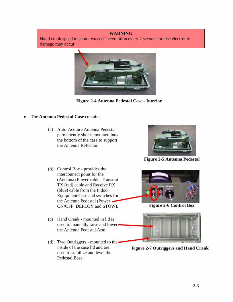
Figure 2-4 Antenna Pedestal Case - Interior
WARNING Hand crank speed must not exceed 1 revolution every 2 seconds or else electronic damage may occur.

2-4
Figure 2-9 Outriggers Installed
(4) Remove the two Outriggers by turning the
black knobs counterclockwise to remove them from the lid.
(5) Install the Outriggers to the pre-drilled holes
located on the front and rear of the Antenna Pedestal Case. (Turn the black knobs clockwise).
(6) The Outriggers are used to stabilize, level, and raise the
base of the antenna pedestal off the ground to allow proper water drainage. Attach the Antenna Pedestal base by using the adjustable feet mounted on the outriggers (within +/- 3 degrees of horizontal). When raising the pedestal base make sure the outriggers feet have firm contact with the ground.
(7) Ensure that Control Box “POWER” switch is set to “OFF” (DOWN). (Figure 2-6) c. Unpack and Identify the Radio Frequency (RF) Equipment Case Components. The case
contains eight items (refer to Appendix E, System Equipment Checklist).
(1) Place RF Equipment Case on a flat surface. (2) Press the pressure release valve located on the case. (3) Turn clasps counter-clockwise to remove the covers. (4) Inspect the components.
Figure 2-8 Outrigger Connections
Figure 2-10 RF Equipment Case
NOTE
Do not place the Pedestal Base in soft sand or mud as the Outriggers may not properly support the weight of the Pedestal Base. You may also place the Pedestal Base on a pallet or any other stable or level surface.
CAUTIONS • The RF Equipment Case weighs 121lbs. Use safe lift and carry procedures
when handling the case. This is a two-person lift and carry. • Keep case closed and latched when not accessing equipment to minimize the
possibility of injury or snagging clothing.

2-5
• The RF Equipment Case contains:
(a) Antenna Feed Horn assembly with 4w BUC and LNB.
(b) LNB’s
NOTE
The CSS VSAT 1.2M System has three LNB’s to provide worldwide frequency coverage. LNB's are numbered 1, 2, and 3. The system is shipped with the U.S. model installed, which is LNB - 2. The European or Intelsat model LNB’s will need to be installed based on geographic location and/or frequency assigned from the satellite service provider. See Table 2-1 for summary of frequencies.
Figure 2-13 LNB’s
(5) Cable Reel
(2) Compass/Inclinometer
(4) Antenna Feed Horn w/ 4w Block up Converter (BUC) and LNB #2
(6) Binder with Software CDRom’s and satellite reference card
(3) Ground Fault Interrupter (GFI)/AC Power Cord
(1) Low Noise BlockDown Converter (LNB) 1 and 3
Figure 2-12 Antenna Feed Horn Assembly
Figure 2-11 RF Equipment Case - Interior
(7) Operational Reference Guide (ORG)

2-6
Figure 2-14 Cable Reel
Figure 2-15 Compass/Inclinometer
Table 2-1 LNB Worldwide Frequencies
(c) Inter-Facility Link (IFL) Cable Reel contains the (Antenna)
Power cable, Transmit TX (red) cable and Receive RX (blue) cable for the Antenna Pedestal. These 150 ft. long cables are combined inside a protective nylon or rubber sleeve.
(d) Compass/Inclinometer - used to perform initial placement of
the equipment. It allows the setup personnel to verify a clear line of sight (LOS) from the Antenna to the Reference and Data Satellites.
(5) Remove the Compass/Inclinometer. Use the Compass/Inclinometer to verify that the direction and elevation to the satellite is unobstructed. Return the Compass/Inclinometer to the case.
LNB Number Part Number Input Frequency Output Frequency
Europe 1 NJR2537S 10950 – 11700 MHz 950 – 1700 MHz
US 2 NJR2535S 11700 – 12200 MHz 950 – 1450 MHz
Intelsat (other areas) 3 NJR2536S 12250 – 12750 MHz 950 – 1450 MHz

2-7
d. Unpack and Identify the Indoor Equipment Case Components. The case has front and back removable covers (refer to Appendix E, System Equipment Checklist).
(1) Place case on a flat surface.
(2) Press the pressure release valve located on the case.
(3) Turn clasps counter-clockwise and lift to
remove the lid.
(4) Inspect the components. • The Indoor Equipment Case is a 4-rack-unit that includes the equipment to connect a
user’s Local Area Network (LAN) to the Global Satellite Network.
(a) Modem Tray - holds the Satellite Modem, Modem power supply, 8-port Ethernet Switch, Switch power supply and the interface board for the Antenna Pedestal.
(b) Laptop (on pull out tray) - monitors CSS VSAT Network. (c) Zippered pouch (inside cover) - contains the Antenna Controller Unit (ACU)
and reusable fan filters.
NOTES
• The Indoor Equipment Case must be placed within reach of an external power source from 90 – 260 v AC output.
• Do not place in direct sunlight or in an extremely dusty environment and allow for sufficient air circulation.
CAUTIONS • The Indoor Equipment Case weighs 93lbs. Use safe lift and carry procedures
when handling the case. This is a two-person lift and carry. • Keep case closed and latched when not accessing equipment to minimize the
possibility of injury or snagging clothing.
Figure 2-16 Indoor Equipment Case

2-8
(5) Hang the covers on each side of the case.
(6) Remove the Cable Reel and the Ground Fault Interrupter (GFI)/AC power cord from the RF Equipment Case and place them within 6 feet of the Indoor Equipment Case.
(1) Connect the power cable to the
AC power connector on the rear panel of the Indoor Equipment case. Connect plug end into an external power source.
Figure 2-18 Indoor Equipment Case with Hanging Covers
e. Indoor Equipment Connections.
Figure 2-17 Indoor Equipment Case with Pouch
Figure 2-19 Indoor Equipment Case Front View
Figure 2-20 Indoor Equipment Case Rear Panel
CAUTION Keep case closed and latched when not accessing equipment to minimize the possibility of injury or snagging clothing.
CAUTION The IFL Cable Reel weighs 66lbs. Use safe lift and carry procedures when handling the reel. This is a two-person lift and carry.

2-9
(2) Ensure the GFI is working properly by pressing the “RESET” button to turn on. The LED should be green.
Figure 2-21 Ground Fault Interrupter (GFI)
(3) At the Cable Reel,
release the brake by moving the “Brake Force Adjustment” lever to the “SOFT” or “FREE” position before unrolling cable.
NOTES
• “SOFT” has resistance tension on the cable whereas “FREE” has no resistance tension • Make sure the 6-foot section of cable on the side of the reel is secure prior to releasing
cable.
RESET
Figure 2-22 Brake Force Adjustment Lever and Cable Reel
NOTES
• All multi-pin connectors such as the power connection use an alignment key that must be carefully mated to ensure a proper quick disconnect (Q/D) connection.
• Be sure that the AC Circuit Breaker on the rear panel, the Antenna Power switch and RF switch on the front panel are set to “OFF” (DOWN).
• Be careful not to trip the AC Circuit Breaker when accessing the rear panel of the Indoor Equipment. It is very sensitive and only has a soft protective cover.
WARNING Keep hands clear of the Cable Reel when unwinding cables. Severe injury to hands can occur.

2-10
(4) Release the bungee cords and
unroll the amount of cable needed to reach the Antenna Pedestal and provide for slack.
(5) Connect the (Antenna) Power cable, Transmit TX (red) cable and Receive RX (blue) cables to the Control Box in the Antenna Pedestal. Follow the color-coding (red to red and blue to blue).
Figure 2-23 Control Box Cable Connections
(6) Return to the Cable Reel. Release bungee cords, unwrap the 6 foot cable coiled on the side of the reel, and connect the (Antenna) Power cable, Transmit TX (red) cable and Receive RX (blue) cable to the rear panel of the Indoor Equipment case. Follow the color-coding (red to red and blue to blue).
Figure 2-24 Indoor Equipment Case
Cable Connections
(7) Set the brake by moving the “Brake Force Adjustment” lever to the “LOCK” position.
Figure 2-25 Brake Force Adjustment Lever - Lock
Antenna Power
TX
RX
WARNING Do not connect or disconnect cables with power applied.
2-11
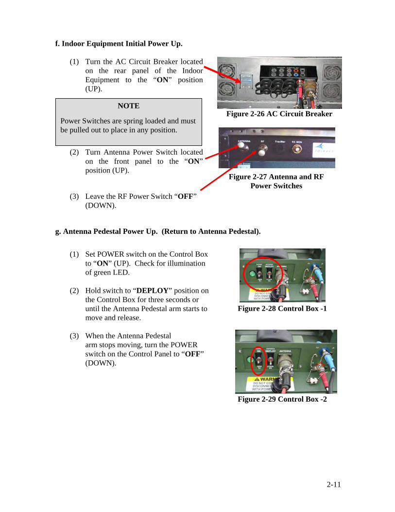
f. Indoor Equipment Initial Power Up.
(1) Turn the AC Circuit Breaker located on the rear panel of the Indoor Equipment to the “ON” position (UP).
(2) Turn Antenna Power Switch located on the front panel to the “ON” position (UP).
Figure 2-26 AC Circuit Breaker
(3) Leave the RF Power Switch “OFF” (DOWN).
g. Antenna Pedestal Power Up. (Return to Antenna Pedestal).
(1) Set POWER switch on the Control Box to “ON” (UP). Check for illumination of green LED.
(2) Hold switch to “DEPLOY” position on
the Control Box for three seconds or until the Antenna Pedestal arm starts to move and release.
Figure 2-28 Control Box -1
(3) When the Antenna Pedestal
arm stops moving, turn the POWER switch on the Control Panel to “OFF” (DOWN).
Figure 2-29 Control Box -2
Figure 2-27 Antenna and RF Power Switches
NOTE
Power Switches are spring loaded and must be pulled out to place in any position.

2-12
h. Unpack and Identify the Reflector Case. The case contains five items (refer to Appendix E, System Equipment Checklist).
(1) Place case on a flat surface. (2) Press the pressure release valve located on the case.
(3) Turn clasps counter-clockwise and lift to remove the lid. (4) Inspect the components.
• The Reflector Case contains:
(a) 1.2 meter Antenna Reflector consists of a top antenna half and a bottom antenna half, together they form a complete reflector dish (the two sections must be assembled).
Figure 2-31 Antenna Reflector Dish
Figure 2-30 Reflector Case
CAUTIONS • The Reflector Case weighs 135 lbs. Use safe lift and carry procedures
when handling the case. This is a two-person lift and carry. • Be careful when assembling the Antenna Reflector. It is made of
re-enforced fiberglass. It is easily damaged. • Keep case closed and latched when not accessing equipment to
minimize the possibility of injury or snagging clothing.
2-13
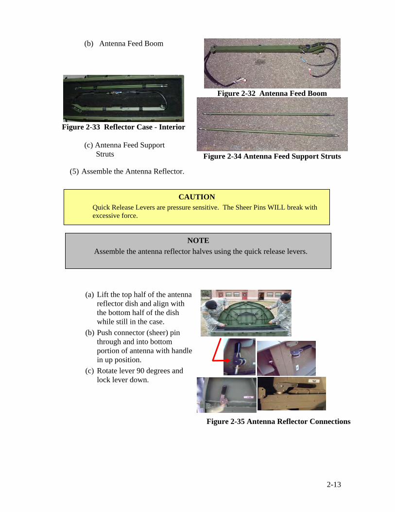
(b) Antenna Feed Boom
Figure 2-33 Reflector Case - Interior
(c) Antenna Feed Support
Struts
Figure 2-32 Antenna Feed Boom
Figure 2-34 Antenna Feed Support Struts
(5) Assemble the Antenna Reflector.
(a) Lift the top half of the antenna reflector dish and align with the bottom half of the dish while still in the case.
(b) Push connector (sheer) pin through and into bottom portion of antenna with handle in up position.
(c) Rotate lever 90 degrees and lock lever down.
Figure 2-35 Antenna Reflector Connections
CAUTION Quick Release Levers are pressure sensitive. The Sheer Pins WILL break with excessive force.
NOTE Assemble the antenna reflector halves using the quick release levers.

2-14
(6) Remove the assembled 1.2 meter dish from the reflector case and lay it on a flat clean surface (i.e., Antenna Pedestal case cover) facing up.
Figure 2-36 Antenna Reflector on a Clean Flat Surface
(7) Remove the Antenna Feed Boom and Antenna Feed Support Struts from the Reflector case. Set the Antenna Feed Support Struts aside.
Figure 2-37 Antenna Feed Boom and Antenna Feed Support Struts
(8) Gently mount the Antenna Feed
Boom by placing the thumbscrew end into the notch at the top of the Antenna Reflector. To tighten Antenna Feed Boom to the Antenna Reflector carefully turn thumbscrews clockwise.
Figure 2-38 Antenna Feed Boom Connection to the Antenna Reflector

2-15
(9) Attach the Antenna Feed Support Struts from the Antenna Reflector to the Feed Boom using the friction-fit ball and socket connections.
Figure 2-39 Antenna Feed Support Struts Connected to Antenna Feed
Boom
Figure 2-40 Antenna Feed Support Struts Connected to the Antenna Reflector
(10) Remove the Antenna Feed Horn assembly from the RF Equipment case.
(11) Align and connect the Antenna Feed Horn assembly to the Antenna Feed Boom with the captive thumbscrew.
Figure 2-41 Antenna Feed Horn Assembly
NOTE
Make sure the correct LNB is installed for the geographic location/frequency of operation. LNB#2 is United States (Table 2-1, page 2-6).
CAUTION Do not pick up the Antenna Feed Horn assembly by the rigid wave guide. It will damage easily.
2-16
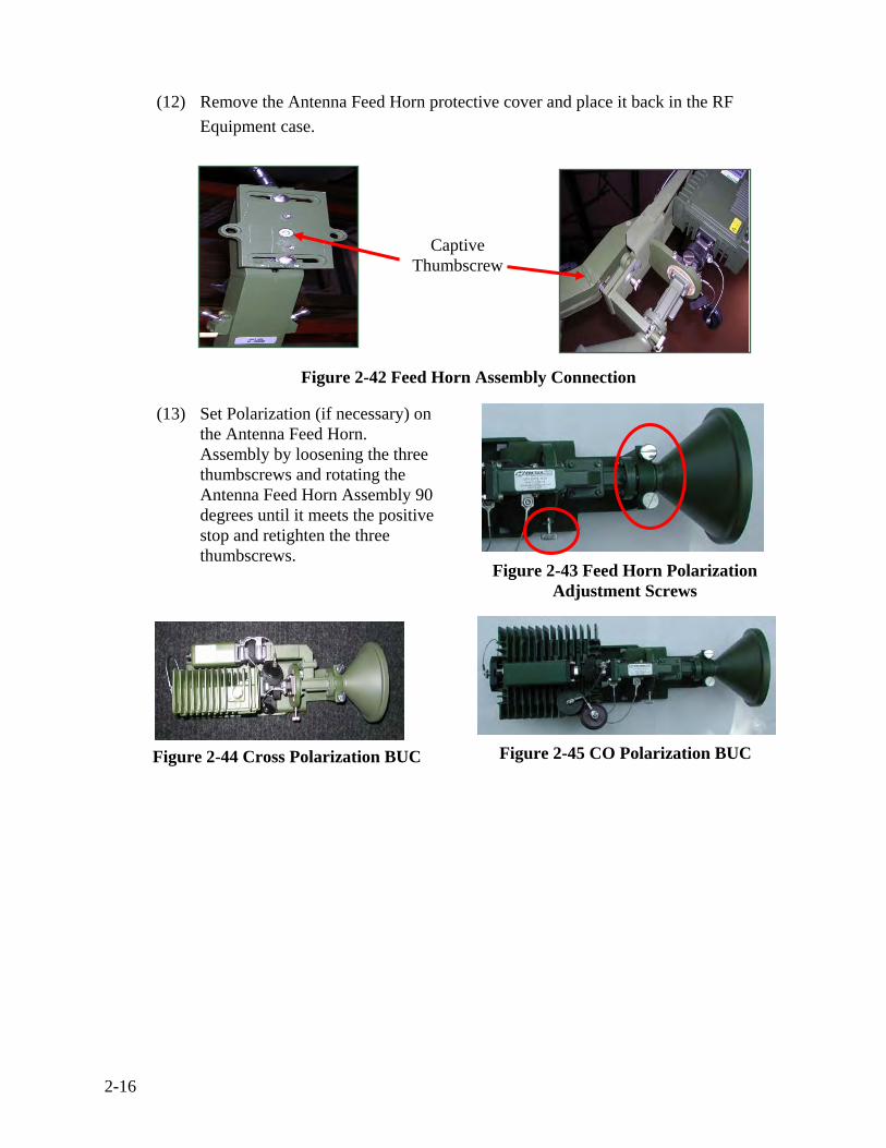
(12) Remove the Antenna Feed Horn protective cover and place it back in the RF Equipment case.
Figure 2-42 Feed Horn Assembly Connection
(13) Set Polarization (if necessary) on the Antenna Feed Horn. Assembly by loosening the three thumbscrews and rotating the Antenna Feed Horn Assembly 90 degrees until it meets the positive stop and retighten the three thumbscrews.
Figure 2-43 Feed Horn Polarization Adjustment Screws
Figure 2-44 Cross Polarization BUC
Figure 2-45 CO Polarization BUC
Captive Thumbscrew

2-17
(14) Connect the Transmit TX (red) cable to the BUC and the Receive RX (blue) cable to the LNB.
Figure 2-46 Cable Connections
(15) Carefully place the assembled Antenna Reflector onto the Antenna Pedestal mounting wedge.
Figure 2-47 Assembled Antenna Reflector Placed on the Mounting Wedge
(16) Secure the Antenna Reflector in place using the four ¼ turn fasteners.
Figure 2-48 ¼-Turn Fasteners (17) Connect the BUC (red), LNB
(blue), GPS (yellow) and Compass cables from the Antenna Feed Boom Assembly to the cables from the Antenna Pedestal.
Figure 2-49 BUC, LNB, GPS and Compass
Cable Connections
CAUTION The Antenna Reflector is fragile; two individuals should pick the Antenna Reflector up by placing one hand on the Antenna Feed Boom Assembly and the other hand on the reflector dish (not the feed support struts).

2-18
(18) Wrap the cables around the cable support rod at the back of the Antenna Reflector to secure.
Figure 2-50 Antenna Reflector Cable Support Rod
Figure 2-51 CSS VSAT 1.2M System Assembled

2-19
Figure 2-54 Indoor Equipment Case Front Panel
2.3 Establish CSS VSAT 1.2M System Communication
Figure 2-52 CSS VSAT 1.2M
a. Set POWER switch on the Control Box to “ON”
(UP). Check for illumination of green LED.
Figure 2-53 Control Box
b. At the front panel of the Indoor Equipment case, turn the RF Switch to the “ON” (UP) position, which starts the initialization of the modem.
NOTES
• If the Antenna Reflector is disturbed or bumped during the start-up process, the system may not be able to acquire the reference and/or data satellite. If unable to acquire the satellite, the system will terminate the start up procedure.
• If the Antenna Reflector receives a physical disturbance during operation, the satellite modem lock may be lost, which will shut down the transmit system. The satellite will need to be re-acquired.
WARNING
DO NOT stand in front of or place any portion of your body between the Feed Boom Assembly and the Antenna Reflector. It may cause serious injury to the eyes or any part of the body due to radiation.

2-20
c. Open the laptop tray cover by turning the two silver knobs counterclockwise, and pull out the laptop tray by the silver knob until it locks into place.
d. Open the Laptop Computer; push the “ON” button and log on to the laptop using the username “admin” and the password “__________________”.
2.4 ViewSAT Application Overview
a. From the desktop, double-click the “ViewSAT” icon.
Figure 2-55 ViewSAT Icon
Figure 2-56 System Login Window
b. Click “Login” button (no password is required for User).
NOTES
• A window will appear instructing the user to wait for modem initialization. When starting ViewSAT, both the Antenna Switch and the RF Switch must be on before starting the application.
• The Modem requires approximately 1 minute to initialize and must be completed before ViewSAT can monitor its status.
• Starting ViewSAT prematurely will cause erroneous readings. Should this happen, restart
the modem (by turning off the RF Switch and then turning it back on again).
2-21
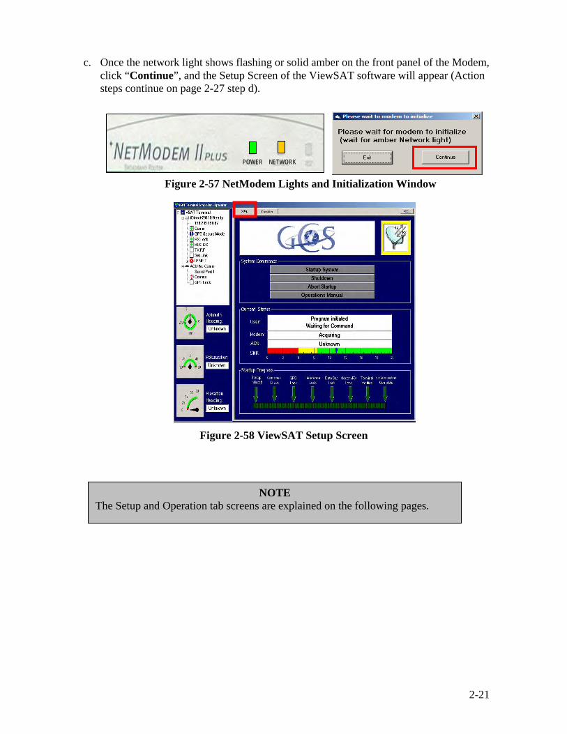
c. Once the network light shows flashing or solid amber on the front panel of the Modem, click “Continue”, and the Setup Screen of the ViewSAT software will appear (Action steps continue on page 2-27 step d).
Figure 2-57 NetModem Lights and Initialization Window
Figure 2-58 ViewSAT Setup Screen
POWER NETWORK
NOTE The Setup and Operation tab screens are explained on the following pages.

2-22
(1) Setup Tab Screen Boxes.
(a) ViewSAT Status Tree Box
Figure 2-59 ViewSAT Status Tree Box

2-23
(b) ViewSAT Reference Box
1 Azimuth Meter - Reports the VSAT’s current azimuth angle sent from the ACU.
2 Polarization Meter - Reports the VSAT’s current polarization angle sent from the ACU.
3 Elevation Meter - Reports the VSAT’s current elevation angle sent from the ACU.
(c) ViewSAT Traffic Meter Box. Indicates the status of the transmit and receive carriers of the satellite modem. Green arrows indicate transmitted and received data, while yellow arrows indicate incomplete link in the associated direction. These indications are the same as shown from the “RX Lock” and “TX RF” tree LEDs.
Figure 2-60 ViewSAT Reference Box
Figure 2-61 ViewSAT Traffic Meter Box
2-24
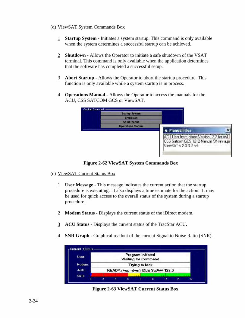
(d) ViewSAT System Commands Box
1 Startup System - Initiates a system startup. This command is only available when the system determines a successful startup can be achieved.
2 Shutdown - Allows the Operator to initiate a safe shutdown of the VSAT
terminal. This command is only available when the application determines that the software has completed a successful setup.
3 Abort Startup - Allows the Operator to abort the startup procedure. This
function is only available while a system startup is in process.
4 Operations Manual - Allows the Operator to access the manuals for the ACU, CSS SATCOM GCS or ViewSAT.
(e) ViewSAT Current Status Box
1 User Message - This message indicates the current action that the startup procedure is executing. It also displays a time estimate for the action. It may be used for quick access to the overall status of the system during a startup procedure.
2 Modem Status - Displays the current status of the iDirect modem.
3 ACU Status - Displays the current status of the TracStar ACU.
4 SNR Graph - Graphical readout of the current Signal to Noise Ratio (SNR).
Figure 2-63 ViewSAT Current Status Box
Figure 2-62 ViewSAT System Commands Box

2-25
(f) ViewSAT Startup Progress Box. This series of startup “milestones” documents all of the steps of a successful system startup. During startup, the progress bar and associated “checks” will illuminate as the startup procedure commences. It is a useful troubleshooting tool because any failure during system startup will be identified and the operator will be informed. The software may also make helpful suggestions to alleviate the problem.
(2) Operation Tab Screen View.
Figure 2-64 ViewSAT Startup Progress Box
Figure 2-65 ViewSAT Operation Tab View
2-26
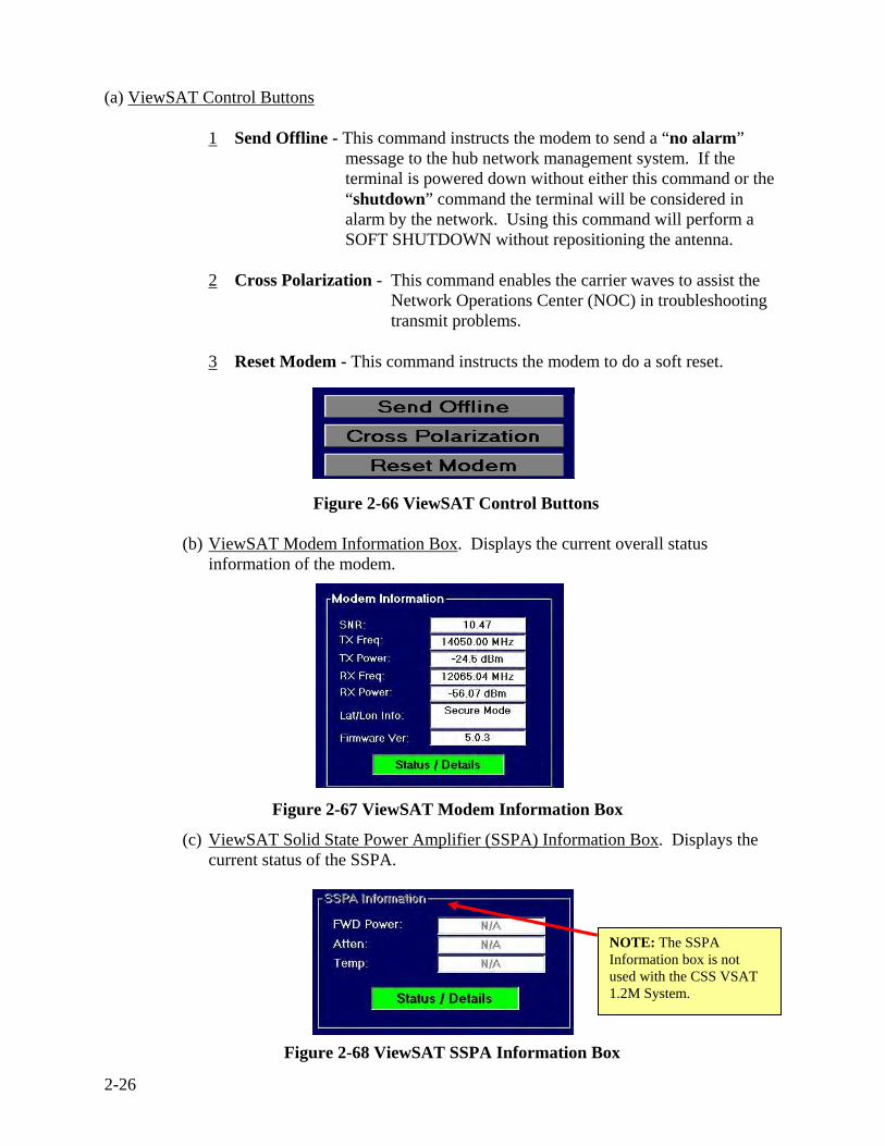
(a) ViewSAT Control Buttons
1 Send Offline - This command instructs the modem to send a “no alarm” message to the hub network management system. If the terminal is powered down without either this command or the “shutdown” command the terminal will be considered in alarm by the network. Using this command will perform a SOFT SHUTDOWN without repositioning the antenna.
2 Cross Polarization - This command enables the carrier waves to assist the
Network Operations Center (NOC) in troubleshooting transmit problems.
3 Reset Modem - This command instructs the modem to do a soft reset.
Figure 2-66 ViewSAT Control Buttons (b) ViewSAT Modem Information Box. Displays the current overall status
information of the modem.
(c) ViewSAT Solid State Power Amplifier (SSPA) Information Box. Displays the current status of the SSPA.
Figure 2-67 ViewSAT Modem Information Box
NOTE: The SSPA Information box is not used with the CSS VSAT 1.2M System.
Figure 2-68 ViewSAT SSPA Information Box

2-27
(d) ViewSAT Antenna Control Unit (ACU) Information Box. Displays ACU GPS parameters as well as the overall ACU status.
Figure 2-69 ViewSAT ACU Information Box
(e) ViewSAT Satellite Position Lookup. Displays the Satellite Lookup of the ACU
Pedestal by the GPS Parameters
Figure 2-70 ViewSAT Satellite Position Lookup
(f) ViewSAT IP Subnet Address Box. Displays a list of reserved IP addresses for the CSS VSAT and their availability.
Figure 2-71 ViewSAT IP Subnet Address Box

2-28
(f) There are 16 IP addresses assigned to a CSS VSAT 1.2M System. Two are not assignable and two are assigned to the modem and laptop. 12 IP addresses are available for the user to utilize. If the VoIP phones are operational there will remain a total of 10 IP addresses for use.
___ Network (IP not available)
___ Modem
___ Laptop
___ Available
___ Available
___ Available
___ Available
___ Available
___ Available
___ Available
___ Available
___ Available
___ Available
___ VoIP (designated)
___ VoIP (designated)
___ Broadcast (IP not available)
9
Have IP Phones but no Router
10
199.209.___.
16 assigned to each system
EXAMPLE OF IP ADDRESS
SCHEME PER SYSTEM
Have Router but no IP Phones
11
No Router and No IP Phones
12
Figure 2-72 IP Address Schematics

2-29
d. Click the “Startup System” button and the Confirm Startup window appears.
e. Click “Yes” and the Assemble Hardware window appears.
(1) Use the following checklist to verify the conditions on the Status Tree Box:
(a) Both Modem Comm and ACU Comms LED’s should be green.
(b) Ensure Modem GPS indicates “Secure Mode ( )” and ACU GPS LED is green.
(2) Correct any of these conditions before proceeding.
f. Click “OK” on the Assemble Hardware box and the LNB Selection window appears.
g. Click “OK” to confirm the correct LNB is installed and the “Reset Window” appears.
Figure 2-75 Assemble Hardware Window
Figure 2-76 LNB Selection Window
Figure 2-73 ViewSAT Setup Tab
Figure 2-74 Confirm Startup Window

2-30
h. Click “Yes” and the Auto Acquisition process will begin.
NOTE
You will then be asked if you wish to reset the ACU frequency settings. It is best to reset these settings at this time if you have changed your physical location.
Figure 2-77 Reset ACU Frequency Window
Figure 2-78 ViewSAT Startup Screen

2-31
i. The auto acquisition software will execute the following steps:
(1) The System will verify its heading utilizing the Compass located on the Antenna Feed Boom.
(2) Determine the Pedestal’s exact location on the earth utilizing GPS Triangulation technology.
(3) Scan for and peak on the Reference Satellite for maximum signal strength.
(4) Scan for and peak on the Data Satellite for maximum signal strength.
(a) Once the auto pointing process is finished, the system modem will obtain a satellite link, IP Network connectivity, and access to the LandWarNet.
(b) The startup progress bar will indicate when each step in the Auto Acquisition process is reached.
(c) The last known status of the ACU can be viewed in the current status section.
NOTE Do not make changes or attempt to reposition the antenna pedestal during the auto acquisition process.
Figure 2-79 Setup Screen View

2-32
NOTE
If any of these steps fail, an indication will be displayed on this line. The system startup will not be complete and corrective action must be taken before re-starting the start up process.
k. Startup will be complete when the Startup Progress bar is completely lit and the IP Net Icon in the ViewSAT Status Tree Box turns green.
l. When Network Acquisition is
complete, Setup Screen shows: – Green Progress Bar – Green LED’s and – Green Dish Icon Frame
indicating “Good to Go” for IP Traffic (Time may vary but wait approximately 15 minutes (from startup) to allow the network modem to connect to the hub station)
j. This error message may be received because the ViewSAT program could not access the NMS due to an excessive number of other terminals accessing the network at the same instant.
– Click “OK” and the system will re-acquire in approximately 5 minutes.
Figure 2-80 Setup Screen ViewSAT Error
Figure 2-81 Setup Screen Acquisition Status

2-33
m. Open Internet Explorer. The default address is: https://www.us.army.mil.
Figure 2-82 Army Knowledge Online Website
NOTE
If you see the Army Knowledge Online (AKO) homepage, you are successfully connected, if not, you may have to refresh the page. If that does not remedy the problem, perform the troubleshooting steps as found in Appendix B (Page B-8).
2-34
2.5 Basic Troubleshooting Procedures 2.5.1 Troubleshoot the CSS VSAT 1.2M System
a. When troubleshooting the CSS VSAT 1.2M system, you should remember these three steps to solving a problem:
(1) Identify the problem. This entails being able to clearly define and communicate what problem has occurred.
(2) Isolate the problem. Once you have identified the problem, you must then isolate the exact component that is causing the problem.
(3) Correct the problem. Correcting the problem will entail one of the following: cleaning, tightening, and minor adjustments as authorized or evacuating the system to a higher-level of maintenance.
b. Most problems will occur in one of these areas:
(1) Installation. The CSS VSAT 1.2M System is not set up in an acceptable operating condition. Some identifying problems are:
(a) Light Emitting Diode (LED) displaying yellow and red lights.
(b) Pedestal does not have a clear line of sight to the satellite.
(2) Connections. CSS VSAT 1.2M System is set up correctly, but a problem has occurred either immediately after setup or during normal operation. This usually has to do with connections, ports and cables.
(3) Network problems. (a) CSS VSAT 1.2M System appears to be operating normally, but the CSS VSAT
operator cannot obtain signal acquisition and initialization. (b) Identify discrepancies or failures and annotate information on DA Form 2404. (c) Contact the CSSAMO/S-6 for assistance on troubleshooting hardware or
software. If the CSSAMO can not assist in hardware problems, they will advise the CSS VSAT user to contact their supporting Supply Support Activity (SSA). Regional Support Center (RSC) handles all warranty issues and repair/replacement of parts.
(d) Under the direction of the CSSAMO (when available) contact the NOC for assistance with network and/or communications-related failures.
c. If troubleshooting does not resolve the issue, contact your CSSAMO/S-6 for assistance. d. Always document and take notes, include the exact error messages. If the problem needs
to be elevated to a higher level of support, this will make communicating the entire problem easier.
NOTE
Refer to Troubleshooting Table in Appendix B for troubleshooting procedures.

3-1
Chapter III CSS VSAT 1.2M System Interface Devices 3.1 CSS VSAT 1.2M System Interface Devices a. CSS users can connect to the CSS VSAT 1.2M System using the following interface devices:
Hub, Router, Computer, Voice over Internet Protocol (VoIP) phones, Switch and CAISI Bridge Module (CBM).
b. Two examples of the CSS VSAT 1.2M System interface devices (CBM and VoIP phones)
will be discussed in the following sections.
Figure 3-1 CSS VSAT 1.2M System Interface Devices
Laptop Computer
Switch
CBM
Router
Hub
VoIP Phones 7911G /7912G
VoIP 7911G VoIP 7912G

3-2
NOTE
A CBM must be setup and configured. Procedures for CBM configuration can be found in the CAISI TB 11-5895-1691-10.
3.2 CSS VSAT 1.2M System Interface Procedures to the CBM
a. Connect one end of a CAT-5/6 cable (maximum length 100 meters) to any available port on the CBM Hub. The uplink port and port 8 can not be used at the same time.
Figure 3-2 CBM and CAT 5/6 Cable
b. Remove the protective cap from one of the six RJ-45 ports on the rear of the Indoor
Equipment.
Figure 3-3 Indoor Equipment Case RJ-45 Ports c. Connect the other end of the CAT 5/6 cable to the RJ-45 port.

3-3
3.3 CSS VSAT 1.2M System VoIP Phone Models 7911G/7912G Overview
a. VoIP is an acronym for Voice over Internet Protocol. It refers to technologies that enable the transport of voice information using Internet Protocols. Voice is sent in a digital form rather than in an analog form as in the traditional circuit-committed protocols of the Public Switched Telephone Network (PSTN).
b. Internet Protocol (IP) Phones use VoIP to carry phone calls across the Internet, the CSS
SATCOM network, or any other IP network.
c. The VoIP phones issued with the CSS VSAT 1.2M system offer voice connections with other VoIP phones on the CSS VSAT network only. Defense Switched Network (DSN) and commercial calls are not available on this network.
d. The CSS VSAT 1.2M systems are issued with one of two IP phone models by Cisco
Systems, the 7912G and the improved 7911G (in this case the later phone has a lower number).
(1) Each IP phone has four dynamic soft keys to guide the user through core business features and functions.
(2) The LCD display combines intuitive features, calling information, and Extensible Markup Language (XML) services.
(3) All Cisco VoIP phones will accept power via IEEE 802.3af Power-over-Ethernet (PoE) or through an AC power adapter.
NOTES
• CSS VSAT 1.2M System and CAISI equipment do not provide PoE. CSS VSAT VoIP phones must be powered using the AC power adapter.
• Since voice traffic must happen in real time and call quality will suffer if there is high network usage, congestion or competition for bandwidth - voice traffic is given priority on the network! This is done by applying Quality of Service (QoS) parameters through the options files to the netmodems. All the other routers in the network must also have QoS settings giving voice traffic priority.
• NetModem option files are also configured to guarantee bandwidth for voice traffic. Voice traffic is marked in such a way that it triggers Committed Information Rate (CIR) which is essentially dedicated bandwidth. A voice call uses 16K of bandwidth so option files are built which allow the netmodem to reserve a maximum of 32K of bandwidth in the event two voice calls are made simultaneously.
e. The differences between the Cisco IP Phone 7911G and the existing 7912G is that the
7911G offers the following: (1) Enhanced memory permitting broader application capabilities (2) More infrastructure integration options (3) Advanced security (4) Encrypted voice and call management signaling

3-4
(5) Improved call quality through more reliable adaptation to changing network conditions.
(6) An extended software roadmap for future advanced feature support. 3.4 Unpack and Identify the VoIP Phone Case
(1) Place VoIP Phone Case on flat surface next to the Indoor Equipment Case.
(2) Lift the flaps up and carefully open case lid.
(3) Inspect the components.
(4) Remove the following components from case and place next to Indoor Equipment Case. a. VoIP Phones (2) b. Handset (2) c. Power cord (3 prong) (2) d. DC power supply (2) e. Footstand (2) f. RJ-45 Coupler is used to
extend the CAT 5 cable (2) (picture not shown).
g. CAT 5/6 cable (8 or 25ft) (2)
(5) Close VoIP Phone Case lid, re-latch claps and set case aside.
(6) Attach handset to rear of VoIP RJ-11 port.
(7) Connect AC power cord to DC power supply.
(8) Connect AC power cord to DC48V port on rear of VoIP phone.
(9) Connect one end of Ethernet cable (8ft or 25ft) to RJ-45 port on rear of VoIP phone 10/100 SW.
NOTE Place the VoIP Phone case next to the Indoor Equipment Case and external power source.
Figure 3-4 VoIP Phone Case Opened and Closed
Figure 3-5 VoIP Phone and Handset
Figure 3-6 Power Cord and DC Power Supply
Figure 3-7 CAT 5/6 Cable and Footstand

3-5
(10) Connect other end of Ethernet cable (8ft or 25ft) to any available RJ -45 on rear of Indoor Unit.
(11) Attach footstand to the four grooves on the rear of VoIP phone by squeezing and pressing down on the footstand.
(12) Connect power supply to an external power source.
Table 3-1 Cisco VoIP Phone Models 7911G/7912G Legend 1 LCD screen Displays features such as the time, date, your phone number,
caller ID, call status, and soft key tabs. 2 Cisco IP Phone Series Indicates your Cisco IP Phone model number. 3 Soft keys
- Redial - NewCall - Message - More
Enable you to engage any of the functions displayed on the corresponding LCD screen tabs. Soft keys point to feature options displayed along the bottom of your LCD screen. Soft key functions change depending on the status of your phone (i.e., if the phone is active or idle).
4 Navigation button Enables you to scroll through text, highlight menu items, and select calls displayed on the LCD screen. Also provides access to speed dial numbers.
5 Menu button Displays a menu that provides access to a voice messaging system, phone logs and directories, settings and services.
6 Hold button Places the active call on hold, resumes a call on hold, and switches between an active call or an inactive call and a call on hold.
7 Keypad Works exactly like the keypad on a traditional telephone. 8 Volume button Increases and decreases volume for the handset and speaker. Also
controls the ringer volume (if on-hook). 9 Handset Functions like a traditional handset. The light strip at the top of
the handset blinks when the phone rings. 10 Footstand Allows the phone to stand at a convenient angle on a desk or
table.
Figure 3-8 Cisco VoIP Phone Model 7911G/7912G

3-6
3.5 VoIP Operations
3.5.1 Changing VoIP Phones IP Address
a. Disabling Dynamic Host Configuration Protocol (DHCP)
(1) Press the “Globe” button. (2) Scroll to “Settings” and press “Select” or press “number 3” on your VoIP phone. (3) Scroll to “Network Configuration” and press the “Select” key or press “number 2”
(7911G) on your VoIP phone and press the “Select” key. (press “number 3” on 7912G).
(4) Scroll to “DHCP” or press “number 22” (7911G) on your VoIP phone. (Press “number 24” on the 7912G).
(5) To unlock this feature you must press “**#”. (6) Once unlocked, press “No”. (7) Press the “save” and “exit” soft key.
NOTES • If a screen alert displays “software updates” on phone model 7912G, do not
interrupt until complete. • If a screen alert displays “Verifying Load” on phone model 7911G, do not interrupt
until complete. • Do not disconnect VoIP phones unless you need to, otherwise it will take five
minutes before you are able to place a call.
WARNINGS • Do not work on the system or connect or disconnect cables during periods of
lightning activity. • This product relies on the buildings installation for short circuit (over current)
protection. Ensure that a fuse or circuit breaker rated for 120VAC, 15A U.S. (240VAC, 10A international) is used.
• The AC adapter plug-socket combination must be accessible at all times because it serves as the main disconnecting device.
• To avoid electric shock, use only LAN cables for the Network and Access ports. • Personal injury or damage to equipment may occur if an approved Cisco power
supply voltage of 48 V DC is not used with the VoIP phones.
NOTES • You must change the IP address and Default router of the VoIP phones every time
you move from one CSS VSAT to another. • Dynamic Host Configuration Protocol (DHCP) must be disable first before changing
IP addresses of the VoIP phones.

3-7
b. To change VoIP’s IP Addresses. (1) Press the “Globe” button. (2) Scroll to “Settings” and press “Select” or press “number 3” on your VoIP phone. (3) Scroll to “Network Configuration” and press the “Select” key or press “number 2”
(7911G) on your VoIP phone and press the “Select” key. (press “number 3” on 7912G).
(4) Scroll to “IP address” press key or press “number 6” on your VoIP phone. (5) To unlock this feature you must press “**#”. (6) Once unlocked, press “edit”. (7) Delete IP address by using the and enter the new IP address (press * for dots). (8) Once new IP address is entered, press the “validate” soft key and then the “save” soft
key.
c. To change the Default Router IP Addresses. (1) Press the “Globe” button. (2) Scroll to “Settings” and press “Select” or press “number 3” on your VoIP phone. (3) Scroll to “Network Configuration” and press the “Select” key or press “number 2”
(7911G) on your VoIP phone and press the “Select” key. (press “number 3” on 7912G).
(4) Scroll to “Default Router #1” or press “number 10” on your VoIP phone and press “edit”.
(5) To unlock this feature you must press “**#”. (6) Once unlocked, press “edit (7) Delete IP address by using the and enter the “IP address” of the NetModem in
the CSS VSAT that will connect to this phone (press * for dots). (8) Once new IP is entered press the “validate” soft key and then the “save” soft key.
NOTE The arrow key are used to backspace and make corrections.

3-8
3.5.2 CSS VSAT 1.2M System Connection Procedures to a VoIP Phone
a. Connect either VoIP Phone model to the Indoor Equipment case via the RJ-45 Ports.
Figure 3-9 VoIP Phone Rear View and RJ-45 Ports on Indoor Equipment Case
b. Connect AC power to the VoIP Phone (100 – 240v).
c. Wait until the phone displays the time, date, the phone number and “Your current options”.
d. The first phase of a call is the ‘setup’ which begins by taking the phone off-hook.
e. Dialing a number sends the number to a Call Manager located at a remote data facility.
f. The Call Manager determines if the call is authorized. If so, it looks up the IP address of
the remote phone and signals the remote phone to ring.
g. The Call Manager looks up the phone number and finds the IP Address of the remote phone.
h. Once the called party answers, all communication is directly between the two phones. No
further communication with the Call Manager occurs until one party hangs up.
i. During the call, there is a continuous, bi-directional stream of data between the phones whether anyone is talking or not. The data stream ends in both directions when one party hangs up.
1) Network port 10/100 SW 2) Access port 10/100 PC 3) Handset port 4) DC Adaptor port 5) AC-to-DC 48v power
supply 6) AC power cord (100 - 240v)

3-9
Figure 3-10 CSS VoIP Network Pathway
* Dialing Plan Convention 20 = CSS VSAT XXX = VSAT Terminal 01 / 02 = phone #1 or #2 NOC phones 20-000-01 20-000-02
Call Manager is hosted at a Remote Data Center
*Circuits and hardware that connect your teleport to your data center via landlines and routers.
VoIP 7911G VoIP 7912G VoIP 7911G VoIP 7912G

3-10
3.5.3 Place a Call over the Network
a. Displaying the Directory: Model 7911G only:
(1) Press the “Menu” key (aka Globe key).
(2) Press the “number 2” key for “Directories”.
(3) Press the “number 5” key for “Directory Services”.
(4) Press the “number 1” key for “Corporate Directory”.
(a) Enter search criteria and press the “search” soft key or
(b) Press the “search” soft key without entering criteria to display ALL records (displays the first 32 records). To display additional records, press “more” soft key and “next” soft key, etc.
b. Place a call by using any one of the following methods:
(1) Lift the handset and dial a number of another phone on the CSS VSAT network.
(2) Press the “NewCall” soft key and dial the number of a phone on CSS VSAT network.
(3) Press the “Redial” soft key (this will dial the previous number called).
(4) Dial any CSS VSAT network number with the handset on the cradle. Then press the “Dial” soft key or lift the handset.
c. Hold a call:
(1) Press the “Hold” button.
(2) To retrieve a held call, press the “Hold” button again.
d. Monitor a call:
(1) Press the “Monitor” soft key (LED will indicate “Connected).
(2) To disengage monitor, press the “Monitor” soft key again.
e. Manage Call Waiting:
(1) To select among calls waiting on the same line, use the “Hold” button.
(2) Then scroll to the desired number by using the navigation buttons.
f. Call Forwarding:
(1) Press the “more” soft key on your phone.
(2) Press “CFwdAll” soft key, listen for confirmation tone (2 beeps).
(3) Enter the designated call forward number, then listen for confirmation tone (2 beeps).
(4) To end Call Forwarding, press the “more” soft key on your phone.
(5) Press “CFwdAll” soft key and listen for confirmation tone (2 beeps).

3-11
g. Place a Conference Call:
(1) During a call, press the “more” soft key then the “Confrn” soft key.
Figure 3-11 “more” and “Confrn” Soft Keys
(2) Enter the phone number for the conference participant.
(3) When participant is connected press “Confrn” soft key again to connect.
(4) To add another party, repeat above steps. A total of 8 phones can be added (originator plus 7).
h. Transfer a Call without consulting connecting party:
(1) During a connected call, press the “Transfer” soft key.
(2) Enter the recipient number.
(3) When the transfer recipient phone rings, press the “Transfer” soft key again.
i. Transfer a Call consulting transfer recipient:
(1) During a connected call, press the “Transfer” soft key.
(2) Enter the recipient number.
(3) Confirm with transfer recipient.
(4) Press the “Transfer” soft key again, if the recipient would like to speak.
(5) If the recipient would like you to take a message, press the “Hold” soft key to return the original call.

3-12
3.6 CSS VSAT 1.2M System VoIP Phone Basic Troubleshooting
Table 3-2 User VoIP Phone Basic Troubleshooting Symptom Action The soft key needed does not appear on the screen
• Press the “More” soft key to reveal additional keys. • Change the line state (for example, go off-hook or have a
connected call). • Check with your System Administrator to see if the phone is
configured to support that soft key feature.
Phone display remains blank
• Phone is not receiving power. Check power supply.
Phone remains in “Configuring …” or “Registering …” state indefinitely
• Check IP address. • Check the IP Subnet Mask. (always 255.255.255.240) • Check the IP Default Router 1 (on a VSAT network, always the
address of the local NetModem). • Check the TFTP Server 1 IP address. (always 10.55.1.13) • Check the TFTP Server 2 IP address. (always 10.55.1.10) • Verify IP connectivity by pinging the IP phone address from a
workstation, preferably on another VSAT.
Dialed number results in “fast busy”
• Target phone is not on line.
Voice quality is poor
Extreme network conditions may be causing interference. Hang up and try the same call again.
Voice is heard on one phone but not the other
• A network malfunction is permitting voice traffic in only one direction. Try the same dialing number on a different phone on the same VSAT to.
• User may be attempting to use speaker phone. The 7911 and 7912 both have speakers, but not microphones.
Attempting to join multiple conference calls
• When joining multiple conference calls be sure that you have selected at least one call in addition to the active call, which is selected automatically.
Accessing network configuration data
• Press the “Menu” button and select “Settings” scroll to “Network Configuration”.
• Select the network configuration item you want to view. • Press “Cancel” to exit.

3-13
Symptom Action Accessing Status Data
• Press the “Menu” button and select “Settings” scroll to “Status”.
• Select the network configuration item you want to view. • Press “Cancel” to exit.
Accessing Phone Model information
• Press the “Menu” button and select “Settings” scroll to “Model Information”.
• Use the “Navigation” button to scroll through and view model information for your phone.
• Press “Cancel” to exit.
NOTES
• Your system administrator may disable your access to the “Settings Menu”. Therefore, you may not be able to access network configuration data, status data, or model information for your phone.
• Refer to Appendix B for further VoIP phone troubleshooting procedures.
Table 3-2 User VoIP Phone Basic Troubleshooting (continued)

3-14
THIS PAGE IS INTENTIONALLY LEFT BLANK

4-1
Chapter IV CSS VSAT 1.2M System Maintenance 4.1 System Maintenance 4.1.1 General. The CSS VSAT 1.2M system is designed to operate with minimal user input during normal operations. However, when a problem arises, the unit/operator must be aware of what to do.
4.1.2 Maintenance Concept. The Army’s materiel maintenance policy is outlined in Army Regulation (AR 750-1). The Army’s maintenance system consist of two categories,
• Field maintenance, also known as on-site maintenance, repairs and returns, equipment to the operator or the user.
• Sustainment maintenance, also know as off-system maintenance, primary repairs and returns equipment and components to the supply system.
The CSS VSAT 1.2M system follows the Army’s Field maintenance concept but for Sustainment maintenance, it follows the Contractor Logistics Support (CLS) concept. Sustainment maintenance will be provided by the System Contractor for the life of the system or until transitioned to organic support.
Figure 4-1 CSS VSAT Maintenance Chart (CONUS)
* Hawaii & Alaska are included in CONUS Maintenance Chart
CSS VSAT Maintenance Chart (CONUS)
SUSTAINMENT
FIELD
SSA CSSAMO / S-6
Operator / Section Chief
NOC/CSS SATCOM FIELD ENGINEERS
When C
SS
AM
O/S
-6 is not available N
etwork
Netw
ork H
ardware
Softw
are
Hardw
are
Manufacturer
STAMIS LAR
Hardware
Software

4-2
Figure 4-2 CSS VSAT Maintenance Chart (OCONUS)
4.1.3 CSS VSAT 1.2M System Line Replaceable Units (LRUs). CSS VSAT 1.2M System Line Replaceable Units (LRUs) consist of the following cases and their contents: Indoor Equipment Case, Antenna Pedestal Case, RF Equipment Case, Reflector Case and VoIP Phone Case.
4.1.4 Basic Field Level and Contract Logistics Support (CLS) Maintenance Procedures.
a. Maintenance operations for the CSS VSAT 1.2M system unit maintenance include the following: (1) Performance of PMCS.
(a) Conduct visual and manual inspections of external and other easily accessible components.
(b) Cleaning, tightening and minor adjustments are authorized.
(2) Upon recognizing that the CSS VSAT 1.2M system is not functioning properly or is non operational, the user will perform PMCS and common sense basic troubleshooting: (a) Check connections to the CSS VSAT 1.2M system. (b) If a problem is hardware/software, contact the supporting Combat
Service Support Automation Management Office (CSSAMO) or contact the CSS SATCOM Network Operation Center (NOC) if no CSSAMO exist.
(c) Complete DA Form 2404, Equipment Inspection and Maintenance Worksheet that identifies the faulty condition and the status provided by the operator diagnostics or symptoms at the time of failure.
CSS VSAT Maintenance Chart (OCONUS)
SUSTAINMENT
FIELD
SSA
CSSAMO/ S-6
Operator/ Section Chief
Manufacturer
When C
SSAMO
/S-6 or
VSATH
elpD
eskis
not
Netw
ork
Netw
ork
Hardw
are
Software
Hardw
are
VSAT Help Desk
When VSAT H
elp Desk is available
STAMIS LAR
Hardware
Software

4-3
b. The following information must be annotated on DA Form 2404. (1) System, i.e., CSS VSAT 1.2M, LIN Number Z00560. (2) Type of operating system –Windows XP. (3) Part number and type of Line Replaceable Unit (LRU) (e.g., Antenna
Pedestal case and Reflector case, etc). (4) Manufacturer of the failed item – Global Communications Systems (GCS). (5) Symptoms of the failure and results of the diagnostics or troubleshooting
procedures. (6) Serial number of the failed component.
c. When contacted, the CSSAMO will determine whether it is a STAMIS or VSAT
problem. (1) Record the symptoms/problems that the user is experiencing and actions that
led to the problems. Also record any visible damage that the user has noted.
(2) If a software problem exists, the supporting CSSAMO will contact the CSS SATCOM Field Technicians, when available or the CSS SATCOM Network Operations Center (NOC). (a) The CSS SATCOM NOC help desk contact information is:
i. (703) 637-0120 ii. (703) 637-0122 iii Toll Free 1-866-734-6842 (1-866-SEGOVIA) iv VoIP 20-000-01/02
v. Email: [email protected]
(b) Once you have contacted the NOC they will provide you a document ticket number.
(3) If a STAMIS software application cannot be corrected by the supporting CSSAMO, the CSSAMO will contact the installation STAMIS Logistics Assistance Representative (LAR). The STAMIS LARs are located at major installations and field commands to include divisions and separate brigades. The LARs are key emergency-essential (E-E), mandatory mobile individuals assigned to a unit. (a) The STAMIS LAR will: identify, investigate and resolve readiness
problems. (b) LARs will communicate directly with appropriate elements of the
Department of Defense, Defense Logistics Agency and with the Manufacturer Help Desk.
(c) LARs are authorized to coordinate assistance from any element of the logistics support community as needed to support the mission. If the unit supported by the LAR deploys, the LAR also deploys.

4-4
(d) LARs are trained technicians who provide: i. Advice. ii. On-site maintenance. iii. Supply and readiness assistance to soldiers. iv. On the job training. v. Instruction to users on the operation, maintenance, and
troubleshooting of the equipment. vi. Diagnostic/Operator software troubleshooting. vii. Disposal of defective equipment/outdated equipment.
d. If the CSSAMO can not solve the hardware problem, the CSSAMO will advise
the supporting Supply Support Activity (SSA). Be prepared to supply the following information: (1) Identification of Operator (2) System number (3) System type (4) Symptoms (5) Document ticket number provided by the NOC
e. The supporting SSA is responsible for maintaining the CSS VSAT spares and is authorized to swap out defective components (LRUs).
f. If the LRU is exchanged at the Class VII SSA, the user will return to his unit, connect the exchanged LRU and attempt to operate the system.
g. The NOC will contact the CSS VSAT Help Desk if they are unable to fix the problem at their level.
4.1.5 CSS VSAT 1.2M System Help Desk. When the CSS VSAT Help Desk is contacted by the NOC, user or CSSAMO experiencing a problem, the CSS VSAT Help Desk will:
a. Record the symptoms that the user is experiencing and actions that led to the problems. Also record any visible damage that the unit operator has noted.
b. Provide the technical support necessary to restore the system to an operational condition.
c. CSS VSAT Help Desk will advise the CSSAMO on how to resolve the issue.

4-5
4.1.6 Manufacturer - Regional Support Center (RSC) - Sustainment Maintenance a. The Manufacturer performs all maintenance actions above the Field Maintenance
level. LRUs are repaired, rebuilt, refurbished or replaced. The manufacturer facilitates the distribution of all repairs.
b. The Manufacturer/RSC is staffed with a point of contact (POC) during the Principal Period for Maintenance (PPM) hours.
(1) The continental United States (CONUS) RSC operates from 0800 to 1600 hours, Eastern Standard Time Zone (EST), Monday through Friday, excluding federal holidays.
(2) Outside continental United States (OCONUS), the Help-Line operates from 0800 to 1700, Western Asia Time Zone (WAT), Monday through Friday, excluding federal and host nation holidays.
(3) Hours other than PPM are defined as Outside Principal Period for Maintenance (OPPM). The RSC will, at a minimum, provide an answering
service to record calls.
c. The RSC may be staffed 24 hours per day, 7 days a week, during contingencies, exercises or in wartime.
d. The RSC is responsible for the disposition of instructions as well as repair or disposal.
e. Manufacturer/RSC Help Line operator determines, during a telephonic contact with the User/CSSAMO maintenance personnel, the status of the unserviceable LRU.
(1) If the LRU is under warranty, the Manufacturer/RSC Helpline operator provides the shipping instructions for the item to be returned.
(2) If the LRU is not covered under warranty, the Manufacturer/RSC Helpline operator provides the SSA maintenance personnel shipping instructions for the item to be returned.
f. The RSC Help-Line operator talks the User/CSSAMO personnel through a series
of questions or diagnostics for the system described. The objective of the telephonic Help-Line is to preclude costly No Evidence of Failure (NEOF) incidents.
g. The Manufacturer/RSC Help-Line operator obtains the following information
from the DA Form 2407/DA Form 5990-E, Maintenance Request:
(1) Owning unit’s Unit Identification Code (UIC).
(2) Owning unit’s Department of Defense Activity Address Code (DODAAC).
(3) The owning unit’s SSA designation.
(4) CSS VSAT 1.2M system number.
(5) Type of windows Operating System (OS).

4-6
(6) The part number and type of LRU.
(7) Manufacturer of the failed LRU, i.e., Global Communications Systems (GCS).
(8) Symptoms of the failure and results of the diagnostics or troubleshooting procedures.
(9) Serial number of the failed LRU. The RSC prepares and ships a replacement item within 72 hours (3 working days) after receipt of the failed item. The RSC attaches a label to the replacement item that reflects the intended Unit Identification Code (UIC), the type software, the OS, and the date loaded.
(10) Upon receipt of the faulty item from the SSA, the RSC logs the LRU into the RSC database by part number, UIC of the losing unit, and reported fault. The RSC screens LRUs for NEOF.
4.2 Preventive Maintenance Checks and Services (PMCS) Procedures
a. Basic Field Level Maintenance is the first and most critical level of CSS VSAT maintenance. It is the foundation of the maintenance system and requires continuous emphasis by all commanders.
b. Preventive maintenance is the systematic care, servicing, and inspection of equipment. It can prevent the occurrence of trouble, reduce downtime, and maintain equipment in serviceable condition. To ensure the equipment is always ready for a mission, it is important to perform each scheduled PMCS procedure.
c. The cornerstone of Basic Field Level maintenance is the operator performing PMCS. The before, during and after PMCS checks concentrate on ensuring equipment is fully mission capable (FMC).
4.2.1 Routine Checks. Routine checks such as cleaning, dusting, washing, checking for loose and chipped paint, checking for damaged or frayed cables, storing items not in use, covering unused receptacles, checking for system completeness, checking for loose nuts, bolts and screws are not listed as PMCS. Perform the following routine checks Before Operation, During Operation and After every shift and as seen fit during normal operation for personnel and equipment safety.
WARNINGS
• Power down the Indoor equipment Antenna Pedestal equipment and disconnect from power source before beginning any PMCS to prevent electrical shock.
• This equipment contains potentially hazardous voltages. Do not attempt to disassemble the units.
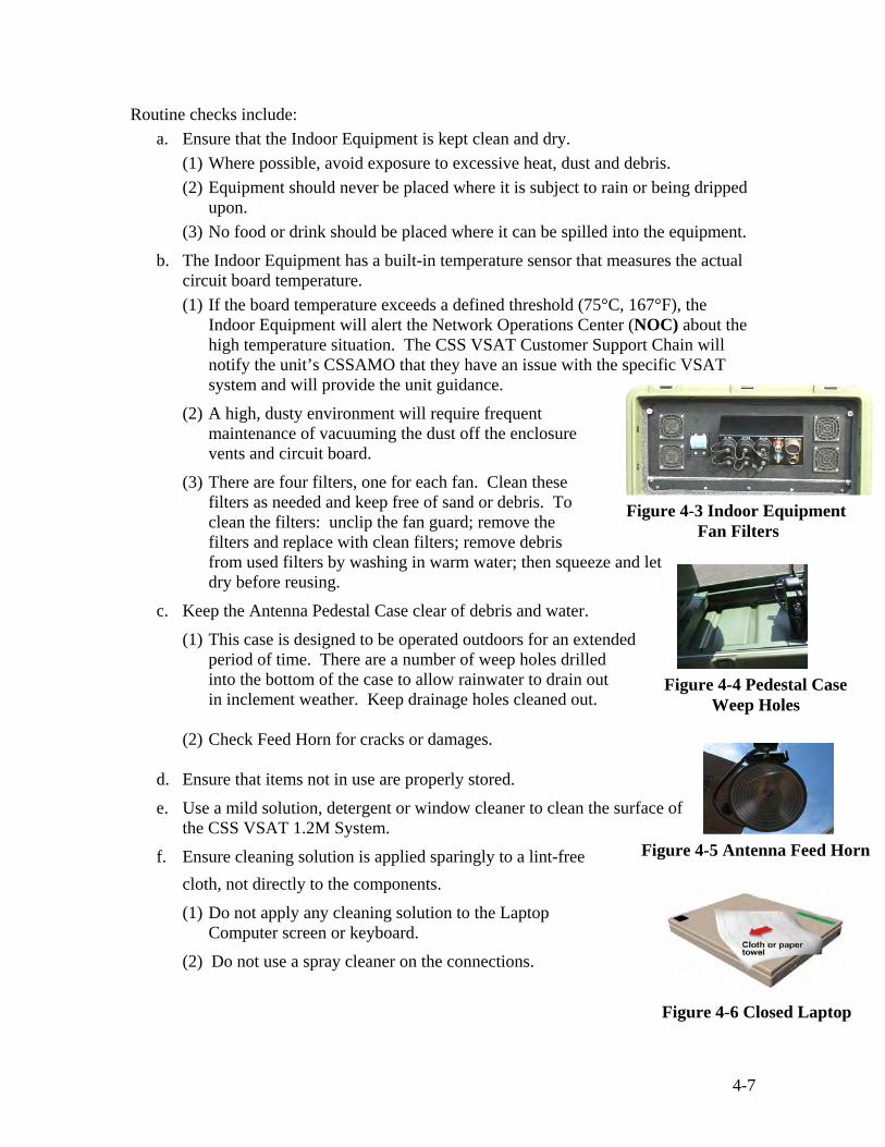
4-7
Routine checks include: a. Ensure that the Indoor Equipment is kept clean and dry.
(1) Where possible, avoid exposure to excessive heat, dust and debris. (2) Equipment should never be placed where it is subject to rain or being dripped
upon. (3) No food or drink should be placed where it can be spilled into the equipment.
b. The Indoor Equipment has a built-in temperature sensor that measures the actual circuit board temperature. (1) If the board temperature exceeds a defined threshold (75°C, 167°F), the
Indoor Equipment will alert the Network Operations Center (NOC) about the high temperature situation. The CSS VSAT Customer Support Chain will notify the unit’s CSSAMO that they have an issue with the specific VSAT system and will provide the unit guidance.
(2) A high, dusty environment will require frequent maintenance of vacuuming the dust off the enclosure vents and circuit board.
(3) There are four filters, one for each fan. Clean these filters as needed and keep free of sand or debris. To clean the filters: unclip the fan guard; remove the filters and replace with clean filters; remove debris from used filters by washing in warm water; then squeeze and let dry before reusing.
c. Keep the Antenna Pedestal Case clear of debris and water.
(1) This case is designed to be operated outdoors for an extended period of time. There are a number of weep holes drilled into the bottom of the case to allow rainwater to drain out in inclement weather. Keep drainage holes cleaned out.
(2) Check Feed Horn for cracks or damages.
d. Ensure that items not in use are properly stored.
e. Use a mild solution, detergent or window cleaner to clean the surface of the CSS VSAT 1.2M System.
f. Ensure cleaning solution is applied sparingly to a lint-free cloth, not directly to the components.
(1) Do not apply any cleaning solution to the Laptop Computer screen or keyboard.
(2) Do not use a spray cleaner on the connections.
Figure 4-3 Indoor Equipment Fan Filters
Figure 4-4 Pedestal Case Weep Holes
Figure 4-5 Antenna Feed Horn
Figure 4-6 Closed Laptop

4-8
g. Perform the following After Operations and Weekly Checks:
(1) Check the equipment for completeness.
(2) Wipe off the exterior surfaces with a mild detergent solution and cloth or paper towel.
h. Weekly, monthly, quarterly and annual PMCS checks are conducted and are the same as After Operations checks.
4.2.2 CSS VSAT PMCS Checklist
a. Item to be Checked, Serviced and Procedures Column. The items listed in this
column indicate what part of the equipment is to be checked or serviced and how to perform the service. B-before, D-daily, A-after, W-weekly, M-monthly, Q-quarterly and Y-yearly. Equipment in storage should be checked quarterly.
b. PMCS is determined by the unit Standard Operating Procedure (SOP).
Table 4-1 User PMCS Checklist
INTERVAL ITEM NO
B D A W M Q Y
ITEM TO BE CHECKED/SERVICED AND PROCEDURES
WARNINGS
• Power down and unplug CSS VSAT components from power outlet before cleaning
• Do not apply any cleaning solution directly on any of the CSS VSAT components
• Place the cleaning solution on a lint free cloth and clean the surface of the device
• Do not place liquids on or near CSS VSAT components and never spray water or cleaner into switches, buttons, data or communications jack, air vents or other openings.
NOTE: If the equipment must be kept in continuous operation, check and service only those items that can be checked and serviced without disturbing operation. Make the complete checks and services when the equipment can be shut down.
* *
* *
* *
* *
* *
* *
1. Inspect/Inventory all equipment cases for completeness. 2. Clean all exterior surfaces.

4-9
INTERVAL ITEM NO B D A W M Q Y
ITEM TO BE CHECKED/SERVICED AND PROCEDURES
* * * * * *
* * * * * *
* * * * * *
* * * * * *
* * * * * *
* * * * * *
INDOOR EQUIPMENT CASE 1. Check the outside of the case for signs of damage: dents,
cracks, punctures and corrosion. 2. Check pressure release valve for serviceability. 3. Check operation of all latches on case. 4. Check interior for signs of damage – missing or damaged tray,
missing screws and protective caps. 5. Check operation of all switches and A/C breaker.
CAUTION: Must be dry before used again. 6. Check all filters in the rear of indoor unit; these can be washed
with water.
* * * * * * *
* * * *
* * * * * *
* * * * * *
* * * * * *
* * * * * *
* * * * * *
ANTENNA PEDESTAL CASE 1. Check cables and connections for tightness and inspect for
signs of wear. CAUTION: Do not spray cleaner directly on electrical connections.
2. Clean all exterior surfaces on case and equipment. 3. Inspect protective caps. 4. Check operation of the power indicator light. 5. Check to make sure the outriggers are clean and free of sand
and dirt in threads. 6. Adjust outriggers (if necessary) 7. Inspect weep holes to ensure that they are free of debris.
* * * * * * * *
* * * * * * * *
* * * * * * * *
* * * * * * * *
* * * * * * * *
* * * * * * * *
RF EQUIPMENT CASE
1. Clean the feed horn assembly (BUC, LNB and Feed Horn) 2. Clean all electrical connections and screw threads. 3. Inspect feed boom screws for bending or wear. 4. Inspect power cable and GFI for wear. 5. Inspect cable reel brake and cable for wear, burns, frays, or
cuts. 6. Clean compass/inclinometer. 7. Inspect LNB's not installed. 8. Inspect all clasps and case surfaces for wear or damage.
* * * * * * *
* * * * * * *
* * * * * * *
* * * * * * *
* * * * * * *
* * * * * * *
REFLECTOR CASE 1. Check for cracks, dents or any other damage to reflector case. 2. Check for cracks, dents or any other damage to reflector dish. 3. Check screw thread holes on reflector for signs of wear. 4. Check ¼ turn fasteners connecting points for wear. 5. Inspect the feed boom and attaching screws. 6. Inspect RF cables and connectors. 7. Inspect feed boom struts.
Table 4-1 User PMCS Checklist (continued)

4-10
4.3 Basic Field Level Troubleshooting Procedures. Refer to paragraph 2.5 for basic field level troubleshooting procedures.
INTERVAL ITEM NO B D A W M Q Y
ITEM TO BE CHECKED/SERVICED AND PROCEDURES
* *
* * * * * * *
* *
* * * * * * *
* *
* * * * * * *
* *
* * * * * * *
* *
* * * * * * *
* *
* * * * * * *
VoIP PHONE CASE 7912G/7911G
1. Check the outside case for signs of damage-dents, cracks, punctures or corrosion.
2. Check the interior for signs of damage-missing components or damaged foam.
3. Check the VoIP phone for signs of damage-dents, cracks or corrosion.
4. Check RJ 45 Coupler for signs of cracks, scratches, dents, or other damages.
5. Check CAT 5/6 Ethernet Cable connectors on both ends are present and are not damaged.
6. Check the connections of the VoIP phone and handset. 7. Check to make sure handset RJ-11 connectors on both ends
are present, there are no signs of frays and are not damaged. 8. Use a paper towel dampened with a mild solution of detergent
or window cleaner to clean the surface of the VoIP phones. 9. Periodically check cable and connections for tightness and
inspect for signs of wear.
NOTE
Refer to Troubleshooting Table in Appendix B for troubleshooting procedures.
Table 4-1 User PMCS Checklist (continued)

5-1
Chapter V Prepare CSS VSAT 1.2M System for Movement and Storage
5.1 Sending the System Offline a. To send a CSS VSAT 1.2M system Offline, use the following steps. (This is used to send
the system Offline while leaving the dish pointed e.g., securing for the day/weekend, PMCS, school house instruction).
(1) Click the “Send Offline” button on the Operations Tab.
(2) Click “OK” on the Confirm window to send unit offline. (To verify that you have taken the system out of the network properly; you will notice the frame around the Traffic Meter Box turns yellow, and the TX RF, SAT Link and IP Net in the Status Tree Box changes).
(3) Close ViewSAT software by clicking on the “X” in the upper right hand corner of the laptop screen.
(4) Select the “Start” and “Shutdown” buttons to turn off and secure laptop.
(5) Secure laptop by releasing the locking tabs on the bottom of the laptop tray.
(6) Set the Antenna and RF Switch to “OFF” on the front panel of the Indoor Unit.
(7) Turn the AC Circuit Breaker located on the rear panel of the Indoor Equipment to “OFF” position.
(8) Turn the Antenna Pedestal power switch located on the Control Box to “OFF”.
b. If the system has been shutdown previously using the “Offline” option, the following steps must be initiated to bring the unit back on line:
(1) Set Power switch on the Control Box to “ON”.
(2) Turn the AC Circuit Breaker “ON”.
(3) Set the Antenna and RF Switch to “ON”
(4) Open laptop and log on.
(5) Double click the “ViewSAT” icon.
(6) Click “Login”.
(7) A window will appear instructing the user to wait for modem initialization. The modem requires approximately 1 minute to initialize and must be completed before ViewSAT can monitor its status.
(8) Once the network light shows flashing or solid amber on the front panel of the Modem, click “Continue” and the Setup Screen of the ViewSAT software will appear.
.

5-2
Figure 5-1 Modem Initialization Window
w 5.2 Performing a SOFT System Shutdown
a. To perform a SOFT system shutdown, click on the “Shutdown” button in the Setup tab.
(1) The antenna is sent into a pre-deploy position for disassembly and packing when the shutdown button is clicked.
(2) The user should only perform a system shutdown using the Shutdown button when the system is being prepared for movement or storage.
NOTE Never turn off the AC power prior to initializing and completing a System (SOFT) Shutdown. Doing so will result in a critical alarm reported at the NOC. If a subsequent startup is required before disassembly, the modem will need to be reset and the application restarted.
Figure 5-2 ViewSAT Setup Screen
NOTE Startup will be complete when the Startup Progress bar is completely lit and the IP Net Icon in the ViewSAT Status Tree Box turns green.

5-3
Figure 5-4 ViewSAT Turn off RF Power Window
Figure 5-5 ViewSAT Notice Window
b. From the Setup screen, click “Shutdown,” you will then be prompted to confirm the shutdown with the following screen:
Figure 5-3 Confirm Shutdown Window
c. Click “Yes” on the “Confirm Shutdown” prompt.
(1) The shutdown sequence will be initiated.
(2) ViewSAT will logoff the network and reposition the satellite terminal to the correct position for disassembly.
d. Turn OFF the RF Switch located on the front panel of the Indoor Equipment Case and then click “OK.”
e. You will be informed when the shutdown sequence has been completed, click “OK.”
f. Close ViewSAT software by clicking on the “X” in the upper right hand corner of the laptop screen.
Figure 5-6 Close ViewSAT Software Window

5-4
Figure 5-8 Control Box
g. On the Exit Program Window, click “OK.”
WARNING
Do not connect or disconnect cables with power applied.
h. Close out all open programs on the laptop.
i. Select the “Start” and “Shutdown” buttons to turn off laptop.
j. Secure laptop by releasing the locking tabs on the bottom of the laptop tray.
k. When the Reflector Dish stops moving, turn off the power switch at the Control Box.
Figure 5-7 ViewSAT Exit Program Window

5-5
Figure 5-11 Cable Stow Clamp
Figure 5-12 ¼ Turn Fasteners
5.3 Packing and Preparing for Movement and Storage Procedures
a. Locate the CSS VSAT 1.2M System Equipment Checklist Card (Appendix E).
b. Inventory and inspect each case and its components as you pack up the system and annotate discrepancies or shortages on DA Form 2404 (Appendix G).
c. Set RF switch at the front panel of the Indoor Equipment Case to “OFF”
d. Unwrap the cables from the support rod at the back of the Antenna Reflector.
e. Disconnect the BUC, LNB, GPS and Compass cables from the rear of the Antenna Reflector. Replace protective caps. Secure the Antenna Pedestal cables in the cable stow clamp (Figure 5-11).
f. Carefully remove the assembled Antenna Reflector from the mounting wedge by turning the four ¼ turn fasteners counter clockwise.
Figure 5-9 Antenna Reflector Cable Support Rod
Figure 5-10 BUC, LNB, GPS and Compass Cables

5-6
Figure 5-13 Antenna Reflector on Flat Surface
Figure 5-15 BUC and LNB with Cables
Figure 5-14 Antenna Feed Horn with Protective Cover
Figure 5-16 Set Polarization to Stow
g. Lay the assembled Antenna Reflector flat on a clean surface (i.e., Antenna Pedestal Case) and facing up.
h. Replace the protective cover over the Antenna Feed Horn.
i. Disconnect Transmit TX (red) cable to the BUC and Receive RX (blue) cable to the LNB on the Antenna Feed Horn.
j. Reset polarization (if necessary) by loosening the three thumbscrews on the Antenna Feed Horn assembly and rotate the BUC 90 degrees to the negative stop and retightening thumbscrews.

5-7
Figure 5-17 Removing Antenna Feed Horn Assembly
Figure 5-18 Antenna Feed Boom Connectors
Figure 5-19 Remove Antenna Feed Support Struts
k. Remove the Antenna Feed Horn from the Antenna Feed Boom Assembly by turning the captive thumbscrew counterclockwise. Place in RF Equipment Case.
l. Remove the Antenna Feed Boom by turning the 3 thumbscrews counterclockwise.
m. Disconnect the Antenna Feed Support Struts from the Antenna Reflector and Antenna Feed Boom.

5-8
Figure 5-20 Antenna Feed Boom and Struts Secured in
Reflector Case
Figure 5-21 Antenna Reflector
Figure 5-22 Packed Antenna Reflector
Figure 5-23 Packed Reflector Case
n. Place Antenna Feed Boom in Reflector Case.
o. Place Antenna Feed Support Struts in Reflector Case.
p. Prepare to disassemble the Antenna Reflector.
q. Place the assemble 1.2 meter dish in the reflector case bottom half first. (i.e. the side where the pressure release valve is).
r. Separate the two halves of the Antenna Reflector dish using the Quick Release Levers.
s. Place the top half of the reflector dish in the foam cut out of the reflector case with top half of dish facing up (the side with the notch for the feed boom assembly).
t. Conduct inventory and inspect the Reflector Case Components – 2-piece Antenna Reflector, Antenna Feed Boom and two (2) Antenna Feed Support Struts.
u. Replace the Reflector Case lid and secure all latches.
CAUTION The Reflector Case weighs 135lbs. Use safe lift and carry procedures when handling the case. This is a two-person lift and carry.
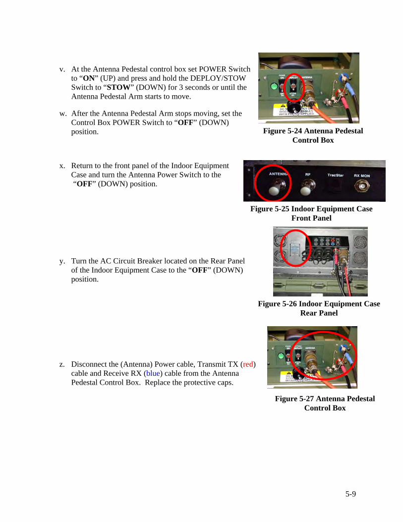
5-9
Figure 5-24 Antenna Pedestal Control Box
Figure 5-26 Indoor Equipment Case Rear Panel
Figure 5-27 Antenna Pedestal Control Box
v. At the Antenna Pedestal control box set POWER Switch to “ON” (UP) and press and hold the DEPLOY/STOW Switch to “STOW” (DOWN) for 3 seconds or until the Antenna Pedestal Arm starts to move.
w. After the Antenna Pedestal Arm stops moving, set the Control Box POWER Switch to “OFF” (DOWN) position.
x. Return to the front panel of the Indoor Equipment Case and turn the Antenna Power Switch to the “OFF” (DOWN) position.
y. Turn the AC Circuit Breaker located on the Rear Panel of the Indoor Equipment Case to the “OFF” (DOWN) position.
z. Disconnect the (Antenna) Power cable, Transmit TX (red) cable and Receive RX (blue) cable from the Antenna Pedestal Control Box. Replace the protective caps.
Figure 5-25 Indoor Equipment Case Front Panel

5-10
Figure 5-28 Outriggers Mounted on Antenna Pedestal Case
Figure 5-29 Outriggers Secured in Antenna Pedestal Case Lid
Figure 5-30 Antenna Pedestal Base
aa. Loosen the adjustable feet on the Outriggers by turning the black knobs counterclockwise. Remove the Outriggers by turning the black knobs counterclockwise.
bb. Place each Outrigger back inside the Antenna Pedestal Case lid. Turn the black knobs clockwise to secure them to the lid.
cc. Conduct an inventory and inspect the Antenna Pedestal Case components – Antenna Pedestal, Hand Crank, Control Box and two (2) Outriggers.

5-11
Figure 5-31 Packed Antenna Pedestal Case
Figure 5-32 Indoor Equipment Rear Panel
dd. Replace the Antenna Pedestal Case lid and secure all latches.
ee. Carry the cable ends from the Antenna Pedestal Case back to the Cable Reel and lay them down to protect the connectors.
ff. Disconnect the (Antenna) Power cable, Transmit TX (red) and the Receive RX (blue) cable from the rear panel of the Indoor Equipment Case. Replace all protective caps.
gg. Disconnect all used RJ-45 ports on the rear panel of Indoor Unit.
CAUTION The Antenna Pedestal Case weighs 170lbs. Use safe lift and carry procedures when handling the case. This is a two-person lift and carry.
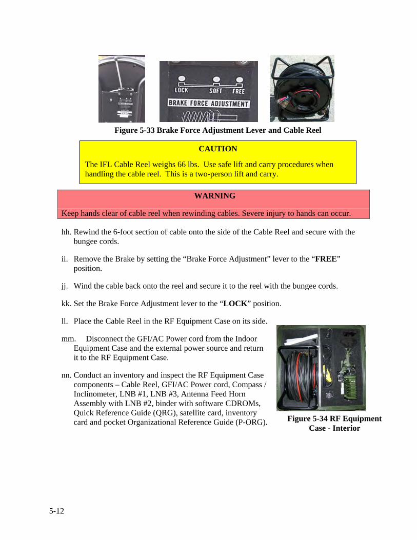
5-12
Figure 5-33 Brake Force Adjustment Lever and Cable Reel
Figure 5-34 RF Equipment Case - Interior
WARNING
Keep hands clear of cable reel when rewinding cables. Severe injury to hands can occur.
hh. Rewind the 6-foot section of cable onto the side of the Cable Reel and secure with the bungee cords.
ii. Remove the Brake by setting the “Brake Force Adjustment” lever to the “FREE” position.
jj. Wind the cable back onto the reel and secure it to the reel with the bungee cords.
kk. Set the Brake Force Adjustment lever to the “LOCK” position.
ll. Place the Cable Reel in the RF Equipment Case on its side.
mm. Disconnect the GFI/AC Power cord from the Indoor Equipment Case and the external power source and return it to the RF Equipment Case.
nn. Conduct an inventory and inspect the RF Equipment Case components – Cable Reel, GFI/AC Power cord, Compass / Inclinometer, LNB #1, LNB #3, Antenna Feed Horn Assembly with LNB #2, binder with software CDROMs, Quick Reference Guide (QRG), satellite card, inventory card and pocket Organizational Reference Guide (P-ORG).
CAUTION The IFL Cable Reel weighs 66 lbs. Use safe lift and carry procedures when handling the cable reel. This is a two-person lift and carry.
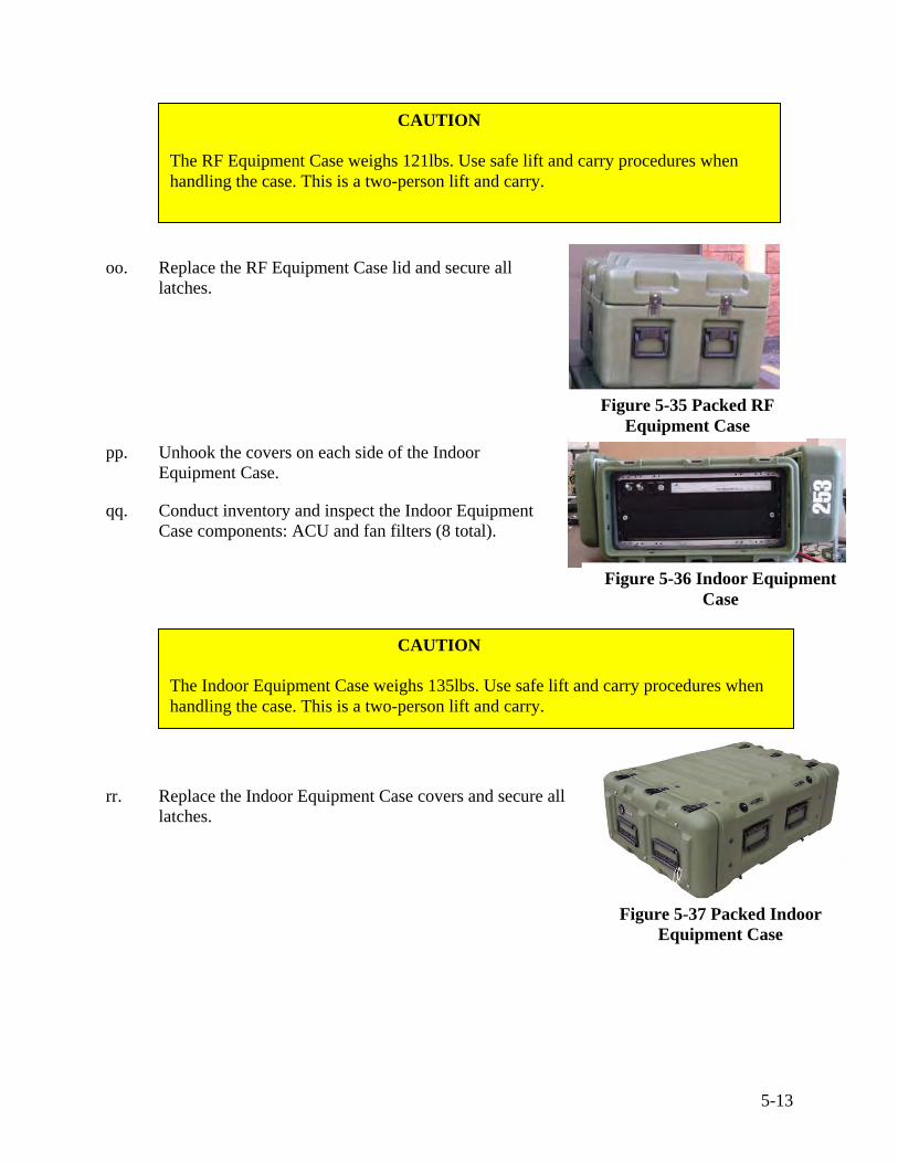
5-13
Figure 5-35 Packed RF Equipment Case
Figure 5-36 Indoor Equipment Case
Figure 5-37 Packed Indoor Equipment Case
oo. Replace the RF Equipment Case lid and secure all latches.
pp. Unhook the covers on each side of the Indoor Equipment Case.
qq. Conduct inventory and inspect the Indoor Equipment Case components: ACU and fan filters (8 total).
rr. Replace the Indoor Equipment Case covers and secure all latches.
CAUTION The RF Equipment Case weighs 121lbs. Use safe lift and carry procedures when handling the case. This is a two-person lift and carry.
CAUTION The Indoor Equipment Case weighs 135lbs. Use safe lift and carry procedures when handling the case. This is a two-person lift and carry.

5-14
ss. Disconnect the power supply to an external power source.
tt. Detach the footstand from the four grooves on the rear of VoIP phone by squeezing and pressing down on the footstand. uu. Disconnect the Ethernet cable from the RJ-45 port on rear of VoIP phone 10/100 SW. vv. Remove AC power cord to DC48V port on rear of VoIP phone. ww. Separate the AC power cord to DC power supply. xx. Detach handset to rear of VoIP RJ-11 port. yy. Conduct inventory and inspect the VoIP Phone Case components: (2) VoIP Phones, (2)
Handsets, (2) 3-prong power cords, (2) DC power supply, (2) Footstands, (2) RJ-45 Couplers and (2) CAT 5/6 cables.
zz. Close the VoIP Phone Case lid and secure all latches.
Figure 5-38 Packed VoIP Phone Case Opened and Closed

5-15
Figure 5-39 CSS VSAT 1.2M System Cases Packed
The CSS VSAT 1.2M System is now packed and ready for movement.
VoIP Phone Case
Reflector Case
VoIP Phone Case
Indoor Equipment Case
RF Equipment Case
Antenna Pedestal Case

5-16
THIS PAGE IS INTENTIONALLY LEFT BLANK

A-1
APPENDIX A
Glossary and Acronyms
Glossary of Terms
Term Acronym Definition
3DES 3DES A method of triple-securing data (encrypt-decrypt-encrypt) for ensuring privacy in satellite VSAT transmissions. Sometimes called Triple DES.
Apogee In satellite communications, most satellites orbit the earth in elliptical patterns with the earth not in the exact center of the orbital pattern. When a satellite is at its furthest point from the earth, it is at the apogee of the orbit. When a satellite is at its closest point to the earth, it is at the perigee of the orbit.
Attenuation The loss in power of electromagnetic signals between transmission and reception points.
Attitude Control The orientation of the satellite in relationship to the earth and the sun.
Azimuth The angle of rotation (horizontal) that a ground based parabolic antenna must be rotated through to point to a specific satellite in a geosynchronous orbit. The azimuth angle for any particular satellite can be determined for any point on the surface of the earth given the latitude and longitude of that point. It is defined with respect to due north as a matter of easy convenience.
Bandwidth The frequency range of a data transmitting/receiving device, which dictates how much data per unit of time, can flow.
Block-Up Converter BUC The BUC is a device used to amplify and convert the modem’s transmit L-Band frequency to Ku, Ka or C-Band for transmission by the CSS VSAT. The BUC receives DC power from the Satellite Modem via the IFL coaxial cable.
Carrier A specific frequency signal, which carries data. (see also Radio Frequency (RF)).

A-2
Term Acronym Definition
Combat Service Support Automated Information Systems Interface
CAISI Wireless Network System. CAISI is made up of 2 modules and one kit – CAISI Bridge Module (CBM), CAISI Client Module (CCM) and System Support Representative (SSR) Accessory Kit.
Co Polarization The observed signature when the transmit and receive polarizations are the same (HH or VV).
Cross Polarization The observed signature when the transmit and receive polarizations are orthogonal (opposite) (e.g. HV).
Data Satellite A communications satellite that will pass your traffic.
Digital Satellite System
DSS A network of satellites that broadcast digital data. An example of a DSS is DirecTV, which broadcasts digital television signals. DSS's are expected to become more important as the TV and computer converge into a single medium for information and entertainment.
Down Link (Outbound)
Establishment of a communications link from an orbiting satellite down to one or more ground stations on Earth.
Down Converter The Down Converter is a device used to convert RF, Ku-Band, Ka-Band or C-Band signals down to L-Band frequencies (950-1700 MHz).
Effective Isotropic Radiated Power
EIRP The strength of the signal leaving the satellite antenna or the transmitting earth station antenna as compared to a monopole or “whip” antenna.
Electromagnetic Interference
EMI A naturally occurring phenomena when the electromagnetic field of one device disrupts, impedes or degrades the electromagnetic field of another device by coming into proximity with it.
Elevation The upward tilt to a satellite antenna measured in degrees required to aim the antenna at the communications satellite.

A-3
Term Acronym Definition
Feed Horn A section of waveguide into which signals from a parabolic dish reflector are aimed. In most parabolic antenna designs, the feed horn is mounted at the reflector's focal point. The output from the feed horn directly feeds the low noise block converter (LNB).
Footprint Geographic area covered by a satellite transmission.
Frame Start Delay FSD The FSD is the delay value required by the operational remote site in a TDMA network to synchronize with the network time plan on any given network/satellite. The value varies with each terminal location and is computed by the NMS based on the remote site Geo Location. It is reported in symbols and is a critical parameter used primarily for acquisition.
Frequency Division Multiple Access
FDMA FDMA is a technique used to allow more than one earth station to share the bandwidth of a satellite transponder. Each earth station is assigned a specific carrier or set of carriers for transmission over a specific portion of the bandwidth.
Geographic Location
Geo Location Given as a geographic Longitude (East/West), Latitude (North/South) and Elevation above sea level used to define a location of the hub and/or remotes sites on the earth’s surface. Typically reported in degrees, minutes and seconds (elevation-meters). Critically important in calculating delay values.
Geostationary Satellite
A satellite orbiting the Earth 22,300 miles above the equator. The orbiting velocity matches the Earth's rotational speed, thereby making the satellite appear stationary with respect to Earth. Satellite positions match the degrees of longitude on the Earth beneath the satellite.
Geosyncronous Satellite
A satellite that is 22,300 miles above the Earth, but is not necessarily centered over the Equator.
Gigahertz GHz One billion cycles per second.

A-4
Term Acronym Definition
Global Information Grid
GIG The globally interconnected, end-to-end set of information capabilities, associated processes and personnel for collecting, processing, storing, disseminating, and managing information on demand to warfighters, policy makers, and support personnel.
Global Positioning System
GPS A worldwide middle Earth Orbit (MEO) satellite navigational system formed by 24 satellites orbiting the earth and their corresponding receivers on the earth. The satellites orbit the earth at approximately 12,000 miles above the surface and make two complete orbits every 24 hours. The GPS satellites continuously transmit digital radio signals that contain data on the satellites location and the exact time to the earth-bound receivers.
Ground Fault Interrupter
GFI Ground Fault Interrupter are devices designed to protect from electrical shock by interrupting power when there is a difference in the currents between the “hot” and “neutral” wires.
For Official Use Only
FOUO DOD information that is not classified CONFIDENTIAL or higher in accordance with DOD 5200.1–R and that may be withheld from public disclosure in accordance with DOD 5400.7–R, which implements the Freedom of Information Act (FOIA). FOUO information, though unclassified, nonetheless is sensitive and warrants protection from disclosure.
Hertz Hz Basic measure of radio frequency characteristics. An electromagnetic wave completes a full oscillation from its positive to its negative pole and back again in what is known as a cycle. A single Hertz is one cycle per second.
Inclination The angle between the orbital plane of a satellite and the equatorial plane of the earth.
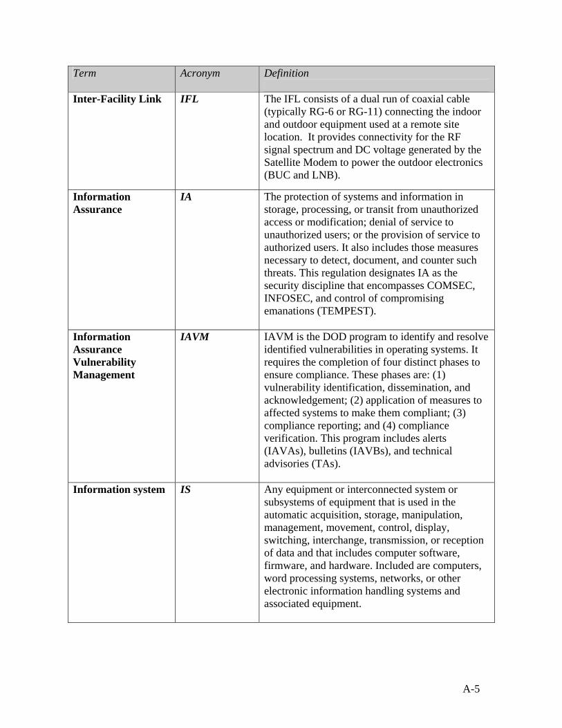
A-5
Term Acronym Definition
Inter-Facility Link IFL The IFL consists of a dual run of coaxial cable (typically RG-6 or RG-11) connecting the indoor and outdoor equipment used at a remote site location. It provides connectivity for the RF signal spectrum and DC voltage generated by the Satellite Modem to power the outdoor electronics (BUC and LNB).
Information Assurance
IA The protection of systems and information in storage, processing, or transit from unauthorized access or modification; denial of service to unauthorized users; or the provision of service to authorized users. It also includes those measures necessary to detect, document, and counter such threats. This regulation designates IA as the security discipline that encompasses COMSEC, INFOSEC, and control of compromising emanations (TEMPEST).
Information Assurance Vulnerability Management
IAVM IAVM is the DOD program to identify and resolve identified vulnerabilities in operating systems. It requires the completion of four distinct phases to ensure compliance. These phases are: (1) vulnerability identification, dissemination, and acknowledgement; (2) application of measures to affected systems to make them compliant; (3) compliance reporting; and (4) compliance verification. This program includes alerts (IAVAs), bulletins (IAVBs), and technical advisories (TAs).
Information system
IS Any equipment or interconnected system or subsystems of equipment that is used in the automatic acquisition, storage, manipulation, management, movement, control, display, switching, interchange, transmission, or reception of data and that includes computer software, firmware, and hardware. Included are computers, word processing systems, networks, or other electronic information handling systems and associated equipment.

A-6
Term Acronym Definition
Internet
A global collaboration of data networks that are connected to each other, using common protocols (for example, TCP/IP) to provide instant access to an almost indescribable wealth of information from computers around the world.
Internet over Satellite
IoS IoS technology allows a user to access the Internet via a satellite that orbits the earth. A satellite is placed at a static point above the earth's surface. The satellite in a fixed position, also referred to as geostationary or geosynchronous, is able to maintain a reliable connection to the antennas on the earth because the satellite orbits the earth at the exact speed of the earth's rotation. Because of the enormous distances signals must travel from the earth up to the satellite and back again, IoS is slightly slower than high-speed terrestrial connections over copper or fiber-optic cables.
Internet Protocol Address
IP Address IP ADDRESS - Internet Protocol, pronounced as two separate letters. IP specifies the format of packets, and the addressing scheme used on the Internet. Every single piece of hardware on the Internet has its own unique IP address. IP by itself is something like the postal system. It allows you to address a package and drop it in the system, but there's no direct link between you and the recipient. TCP/IP (pronounced as 5 letters), on the other hand, establishes a connection between two hosts so that they can send messages back and forth for a period of time. IP addresses are in the form of a 32-bit numeric address written as four numbers separated by periods. Each number can be zero to 255. For example, 10.249.101.24 could be an IP address.
Intranet Similar to the Internet, but is accessible only by the organization’s employees or others with authorization. Usually internal to a specific organization.
iSite Idirect VSAT software application

A-7
Term Acronym Definition
Ka-Band Ka Frequency range of 18-31 GHz.
Ku-Band Ku Frequency for networks based primarily in Europe and North America. Frequency range of 10.7-18 GHz.
LandWarNet It is the combination of infostructure and services across the Army. It provides for processing, storing and transporting information over a seamless network.
Look Angle The angle between the satellite and the horizon.
L-Band The frequency range from 950 to 1950 MHz.
Low Noise Block Converter
LNB The LNB Converter is the equipment in a downlink that takes the high frequency, Ku, Ka or C-Band signal from the satellite and converts it to a lower frequency (L-Band) signal that can be fed through the IFL cable to your modem. Like the BUC, the LNB receives DC power from the Satellite Modem via the IFL coaxial cable.
Line Replaceable Unit
LRU Each case and its components in the CSS VSAT 1M System are considered replaceable: Indoor Equipment, Antenna Pedestal, RF Equipment, and Cable Reel.
Megahertz MHZ The frequency equal to one million Hertz, or cycles per second.
Modem A communications device that modulates signals at the transmitting end and demodulates them at the receiving end.
Network (Satellite)
Any group of terminals (VSAT) communicating through RF frequencies via Satellite.
Network Management System
NMS The NMS is the operational control center for the configuration, monitor and control function of its client network. All Satellite Modems report status in the form of alarms and events to the NMS. It consists of a server and a separate NMS Graphical User Interface (GUI) application contained on one or more PCs.

A-8
Term Acronym Definition
Network Management System Event
NMS Event Events sent by Satellite Modems to the NMS. The events stored are typically status.
Network Operations Center
NOC The center for coordinating all operational and maintenance related activities such as commissioning, remote site monitoring and control, and troubleshooting.
Non-Classified Internet Protocol Router Network
NIPRNET The Army’s version of the Internet. (Also Department of Defense (DoD)). Non-classified or non-secure.
Ortho-Mode Transducer
OMT A waveguide device which allows simultaneous transmit and receive on opposite polarizations from a VSAT/Earth Station feed.
Parabolic Antenna The most frequently found satellite antenna, it takes its name from the shape of the dish described mathematically as a parabola. The function of the parabolic shape is to focus the weak microwave signal hitting the surface of the dish into a single focal point in front of the dish. It is at this point that the feed horn should be located.
Perigee In satellite communications, most satellites orbit the earth in elliptical patterns with the earth not in the exact center of the orbital pattern. When a satellite is at its closest point to the earth, it is at the perigee of the orbit. When a satellite is at its furthest point from the earth, it is at the apogee of the orbit.

A-9
Term Acronym Definition
Ping A utility to determine whether a specific IP address is accessible, and how long it takes to communicate with that address. It is also used to describe the action of using the utility. (On Windows XP, click on “Start” then “Run” and type in “CMD” and press return. The DOS line prompt allows you to type the address you wish to ping. The command would be typed (without the quotes) as: “ping 66.181.32.233” Ping works by sending a packet to a specified address and waiting for a reply. To see ping in action, open a command window (Start/Run, type cmd and return) and type this line into the window:
Polarization POL A technique used by the satellite designer to increase the capacity of the satellite transmission channels by reusing the satellite transponder frequencies. In linear cross polarization schemes, half of the transponders beam their signals to earth in a vertically polarized mode; the other half horizontally polarize their down links. Although the two sets of frequencies overlap, they are 90 degrees out of phase, and will not interfere with each other. To successfully receive and decode these signals on earth, the earth station must be outfitted with a properly polarized feed horn to select the vertically or horizontally polarized signals as desired.
Protected Distribution System
PDS Wire, fiber-optic, or other media telecommunications system that includes terminals and adequate acoustic, electrical, electromagnetic, and physical safeguards to permit its use for the unencrypted transmission of classified information.
Quick Disconnect Caps
Q/D Caps Protective cover for connections on the equipment and cables to keep them clean and dry.
Radio Frequency RF The range of frequencies within which radio waves may be transmitted, from about 150 kilohertz to about 300,00 megahertz.

A-10
Term Acronym Definition
Reference Satellite Reference Satellite is a term applied to a satellite with a known signal and location that can be found quickly by the auto-acquire Antenna.
Reflector This is the part of the Earth Station Antenna, which reflects and focuses the RF signal to/from the feed for processing by the BUC and/or LNB.
Reflector Mount The Reflector Mount is the mounting platform for a reflector assembly. Typical mounts used at remote site locations are non-penetrating roof mounts.
Remote Terminal Unit
A terminal that is not in the immediate vicinity of the IS it accesses. This is usually associated with a mainframe environment and the use of a terminal. Terminals usually cannot operate in a stand-alone mode. Remote Terminal Unit also called a VSAT.
Satellite A sophisticated electronic communications relay station orbiting the earth.
Sensitive information
SI Any information that the loss, misuse, or unauthorized access to or modification of which could adversely affect the national interest or the conduct of Federal programs, or the privacy to which individuals are entitled under Section 552a of Title 5, United States Code (The Privacy Act), but which has not been specifically authorized under criteria established by executive order or an Act of Congress to be kept secret in the interest of national defense or foreign policy. Sensitive Information includes information in routine DOD payroll, finance, logistics, and personnel management systems.
Signal to Noise Ratio
S/N The ratio of the signal power and noise power.
Single Carrier Per Channel
SCPC Technology that uses a separate carrier for each channel of communication.
System Administrator
SA The individual assigned the system administration responsibilities.

A-11
Term Acronym Definition
Telecommunications
Preparation, transmission, communication, or related processing of information (writing, images, sounds, or other data) by electrical, electromagnetic, electromechanical, electro-optical, or electronic means.
Teleport The location containing satellite communications equipment including, but not limited to the earth station antennas, transmit and receiving equipment, hub Satellite Modems, and any required ancillary equipment to facilitate communication between a remote site transmitting and receiving TCP/IP information over a satellite to and from the Internet.
TCP Transmission Control Protocol/Internet Protocol. The most common protocol (set of rules) to allow computers to exchange data. Every device that communicates on the Internet or NIPRNET must have an IP address so information can be sent to it.
Time Division Multiplex Access
TDMA Technology that allows a number of users to access a single radio frequency channel without interference by allotting unique time slots to each user within each channel.
Transponder A wireless communications device usually attached to a satellite. A transponder receives and transmits radio signals at a prescribed frequency range. The term is a combination of the words transmitter and responder. Transponders are used in satellite communications and in location, identification and navigation systems.
Trivial File Transfer Protocol
TFTP TFTP is a network application that is simpler than the File Transfer Protocol (File Transfer Protocol) but less capable. It is used where user authentication and directory visibility are not required. TFTP uses the User Datagram Protocol (User Datagram Protocol) rather than the Transmission Control Protocol (Transmission Control Protocol).

A-12
Term Acronym Definition
Uplink Establishment of a communications link from a ground station up to the orbiting satellite.
Up Converter The Up Converter is a device used to convert transmitted L-Band frequencies (950 - 1700 MHz), to a higher Ku-Band or C-Band signal RF signal. Typically located at the hub or teleport facility.
Very Small Aperture Terminal
VSAT A VSAT represents all of the antenna and electronic equipment located at a remote site used to communicate with a hub as part of a satellite network. Typically reflectors with sizes < 2.4 meters in diameter fall into this category.
ViewSAT CSS VSAT software application.
Virtual Private Network
VPN A network that is constructed by using shared communications medium to connect private nodes. For example, there are a number of systems that enable you to create networks using the Internet as the medium for transporting data. These systems use encryption and other security mechanisms to ensure that only authorized users can access the network and that the data cannot be intercepted.
Voice over Internet Protocol
VoIP A category of hardware and software that enables people to use the internet as the transmission medium for telephone calls by sending voice data in packets using IP.
Waveguide A completely enclosed metallic duct or tube that acts as a transmission line, usually for microwave frequencies. The dimensions of the waveguide are critical to a fraction of a centimeter in order to avoid transmission line loss.
Wavelength The distance while traveling at the speed of light that a radio wave will travel during a single cycle.
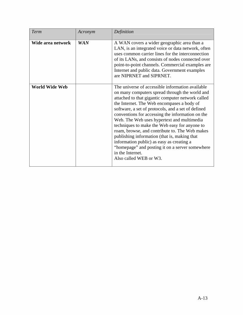
A-13
Term Acronym Definition
Wide area network
WAN A WAN covers a wider geographic area than a LAN, is an integrated voice or data network, often uses common carrier lines for the interconnection of its LANs, and consists of nodes connected over point-to-point channels. Commercial examples are Internet and public data. Government examples are NIPRNET and SIPRNET.
World Wide Web
The universe of accessible information available on many computers spread through the world and attached to that gigantic computer network called the Internet. The Web encompases a body of software, a set of protocols, and a set of defined conventions for accessing the information on the Web. The Web uses hypertext and multimedia techniques to make the Web easy for anyone to roam, browse, and contribute to. The Web makes publishing information (that is, making that information public) as easy as creating a “homepage” and posting it on a server somewhere in the Internet. Also called WEB or W3.

A-14
Abbreviations and Acronyms
Abbreviation Term
1.2M 1.2 Meter
AC
Alternating Current
ACU Antenna Control Unit
AIAP Army Information Assurance Program
AR Army Regulation
AV Anti-Virus
BUC
Block-Up Converter
CAISI
Combat Service Support Automated Information Systems Interface
CAT-5 Category-5
CBM CAISI Bridge Module
CIR Committed Information Rate
CLS Contractor Logistics Support
CONUS
Continental United States
CSS
Combat Service Support
CSSAMO Combat Service Support Automation Management Office
DA Department of the Army
DHCP Dynamic Host Configuration Protocol
DODAAC Department of Defense Activity Address Code
DS Direct Support
DSS Digital Satellite System

A-15
Abbreviation Term
DSN Defense Switched Network
E-E Emergency – essential
Eb/No Energy per bit over Noise density per Hz of bandwidth
EIM Electromagnetic Interference
EIRP Effected Isotropic Radiated Power
EST Eastern Standard Time zone
FDMA Frequency Division Multiple Access
FEC Forward Error Correction Code
FM Field Manual
FMC Fully Mission Capable
FSD
Frame Start Delay
GCS Global Communications Systems
GEO Geostationary Earth Orbit
Geo Location
Geographic Location
GHz Gigahertz
GIG
Global Information Grid
GPS Global Positioning System
GUI Graphical User Interface
Hz Hertz
I/O Input/Output
IA Information Assurance
IAM
Information Assurance Manager

A-16
Abbreviation Term
IAO Information Assurance Officer
IASO
Information Assurance Security Officer
IAVM Information Assurance Vulnerability Management
IAW
In Accordance With
IF
Intermediate Frequency
IFL
Inter-Facility Link
IP Internet Protocol
IS Information Systems
ISSA Installation Supply Support Activity
ISSO Information Systems Security Officer
Kbps
Kilobits-per second
KBps
Kilobytes-per second
Ka Ka-Band
Ku Ku-Band
LAN
Local Area Network
LAR Logistics Assistance Representative
LED
Light Emitting Diode
LNB
Low Noise Block Converter
LOS Line of Sight
LRU
Line Replaceable Unit
Mbps Mega bits per second

A-17
Abbreviation Term
MBps Mega bytes per second
MEO Middle Earth Orbit
MHz Mega-Hertz
NEOF No Evidence of Failure
NIPRNET Non-Classified Internet Protocol Router Network
NMC
Network Management Control
NMS Network Management System
NMS Event
Network Management System Event
NOC
Network Operations Center
OCONUS Outside Continental United States
OEM Original Equipment Manufacturer
OIF
Operation Iraqi Freedom
OMT
Ortho-Mode Transducer
OPPM Outside Principal Period of Maintenance
OS Operating System
P Plug
PC Personal Computer
PDS
Protected Distribution System
PMCS
Preventive Maintenances Checks and Services
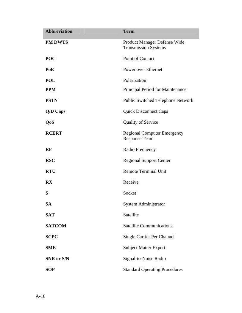
A-18
Abbreviation Term
PM DWTS Product Manager Defense Wide Transmission Systems
POC Point of Contact
PoE Power over Ethernet
POL Polarization
PPM Principal Period for Maintenance
PSTN Public Switched Telephone Network
Q/D Caps
Quick Disconnect Caps
QoS Quality of Service
RCERT Regional Computer Emergency Response Team
RF
Radio Frequency
RSC Regional Support Center
RTU
Remote Terminal Unit
RX
Receive
S
Socket
SA
System Administrator
SAT Satellite
SATCOM
Satellite Communications
SCPC
Single Carrier Per Channel
SME
Subject Matter Expert
SNR or S/N Signal-to-Noise Radio
SOP Standard Operating Procedures

A-19
Abbreviation Term
SSA Supply Support Activity
SSPA Solid State Power Amplifier
STAMIS Standard Army Management Information Systems
TAMMS
The Army Maintenance Management System
TBD To Be Determined
TCP/IP Transmission Control Protocol/Internet Protocol
TDMA
Time Division Multiplex Access
TFTP Trivial File Transfer Protocol
TX
Transmit
UIC Unit Identification Code
UPS
Uninterruptible Power Supply
USB Universal Serial Bus
V Volts
VoIP Voice over Internet Protocol
VPN Virtual Private Network
VSAT
Very Small Aperture Terminal
WAN
Wide Area Network
XML Extensible Markup Language

A-20
THIS PAGE IS INTENTIALLY LEFT BLANK

B-1
APPENDIX B
BASIC TROUBLESHOOTING PROCEDURES
Use this guide to determine where to go for answers. The issues are listed in order that you may encounter them, starting with the set up of the system. (* - 1.2M system)
Issue Additional Condition(s)
Solution
The ground will not support the Outriggers or The Outriggers are not stable or useful.
This is generally caused by being on either ground that is too soft or is sand. Stabilize and level the ground under the base of the pedestal. Do not use the Outriggers.
The Pedestal Base is not level.
The Pedestal Base must be level within at least 10 degrees for the antenna to work properly. The software will indicate the Antenna Pedestal level problem and will display meters to enable adjustments to be made.
Have made all the adjustments within the ViewSAT software but the Pedestal Base is still not level enough
Find a more level location or perhaps find a large flat surface to place under the base.
Check that the IFL Cables are fully connected and color codes match. * Check that the AC Circuit Breaker is set to “ON”. *
Check that the DC Power Switch in the Antenna Pedestal Case is “ON”. *
Antenna Pedestal arm does not deploy.
Check if Antenna Pedestal is programmed for external control. **

B-2
Issue Additional Condition(s)
Solution
Check that the Antenna Power Switch on the Indoor Equipment is set to “ON”. *
Check the Cable connections from the Cable Reel to the Antenna Base and from the Cable Reel to the Indoor Equipment. *
No power to the Antenna Pedestal Base.
Check outside AC power source and its connections to the Indoor Equipment. *
There is no power to the Modem.
Check the RF Equipment Power switch. It must be set to the “ON” position. Set the RF Equipment Power switch to the “ON” position.
The RF Equipment Power switch is on, but there is still no power.
Check to see if there is power to the laptop, Antenna or the Antenna controller display (located to the right of the RF and the Antenna Power switches). If there is no power to any of the other equipment, there is probably no AC power to Indoor Equipment. Check all cables and connections running from the AC input on the Indoor Equipment to the actual AC power source.
The RF Equipment Power switch is on and the Indoor Equipment has power.
The Modem Power LED may be bad. To check to see if the LED is bad, look at the Network LED. If the Network LED is amber or green, but the Power LED remains black, then the Power LED is bad. The Power LED is not mandatory for the equipment to work properly. Please note that the Power LED is bad and inform the unit responsible for repairing the Indoor Equipment.
The Modem Power LED light does not come on.
The Indoor Equipment has power and none of the LEDs are working.
Please note that some of the equipment is located inside the Indoor Equipment. You MUST contact the Network Management Center (NMC) before you attempt any further troubleshooting. • Bad modem power supply (located inside the
Indoor Equipment) • No DC power to modem (located inside the
Indoor Equipment) • Bad power supply input cable • Bad power supply output cable • Bad Modem
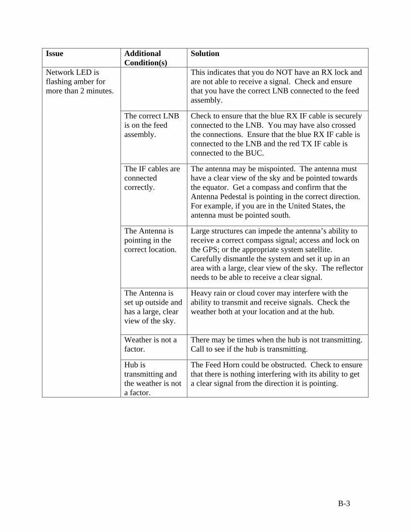
B-3
Issue Additional Condition(s)
Solution
This indicates that you do NOT have an RX lock and are not able to receive a signal. Check and ensure that you have the correct LNB connected to the feed assembly.
The correct LNB is on the feed assembly.
Check to ensure that the blue RX IF cable is securely connected to the LNB. You may have also crossed the connections. Ensure that the blue RX IF cable is connected to the LNB and the red TX IF cable is connected to the BUC.
The IF cables are connected correctly.
The antenna may be mispointed. The antenna must have a clear view of the sky and be pointed towards the equator. Get a compass and confirm that the Antenna Pedestal is pointing in the correct direction. For example, if you are in the United States, the antenna must be pointed south.
The Antenna is pointing in the correct location.
Large structures can impede the antenna’s ability to receive a correct compass signal; access and lock on the GPS; or the appropriate system satellite. Carefully dismantle the system and set it up in an area with a large, clear view of the sky. The reflector needs to be able to receive a clear signal.
The Antenna is set up outside and has a large, clear view of the sky.
Heavy rain or cloud cover may interfere with the ability to transmit and receive signals. Check the weather both at your location and at the hub.
Weather is not a factor.
There may be times when the hub is not transmitting. Call to see if the hub is transmitting.
Network LED is flashing amber for more than 2 minutes.
Hub is transmitting and the weather is not a factor.
The Feed Horn could be obstructed. Check to ensure that there is nothing interfering with its ability to get a clear signal from the direction it is pointing.

B-4
Issue Additional Condition(s)
Solution
The Feed Horn is not obstructed.
The Feed Horn could be damaged or there could be water in the connections. Before you check to see if there is water in the connections, you should ensure that the Antenna power and RF Equipment power switches on the Indoor Equipment are set to Off. Check for water in the connections between the LNB, the Orthomode Transducer (OMT) and/or the feed horn. Once you have checked that the connections are clean and dry, ensure that you reconnect everything tightly.
All connections are clear and the Feed Horn does not appear to be damaged.
The Rigid Waveguide cable could be damaged or there could be water in the connections. With the Antenna power and RF Equipment power switches on the Indoor Equipment set to off, remove the BUC & LNB cable and check the connections. Ensure that all are clear, dry and that the connections are once again tight.
All connections are clear and the rigid waveguide does not appear to be damaged.
Check the RX and TX IF cables at the Pedestal Base and back of the reflector. All connections should be tight.
All connections are good.
Once you have gone through all the other scenarios, the issue may be caused by internal hardware. You MUST contact the Network Management Center (NMC) before you attempt any further troubleshooting. When you contact them, you can suggest that the issue may be in any of the following: • NO DC power to LNB • No 10 MHz reference or too low level • Bad LNB • Bad RX cable in chassis/Antenna and internal to
Antenna • Bad IDIRECT modem • Damaged Rigid Waveguide (not visibly)
Network LED is flashing green for more than 2 minutes.
This indicates that you do NOT have an TX lock and are not able to transmit a signal. Check and ensure that you have the correct LNB connected to the feed assembly.
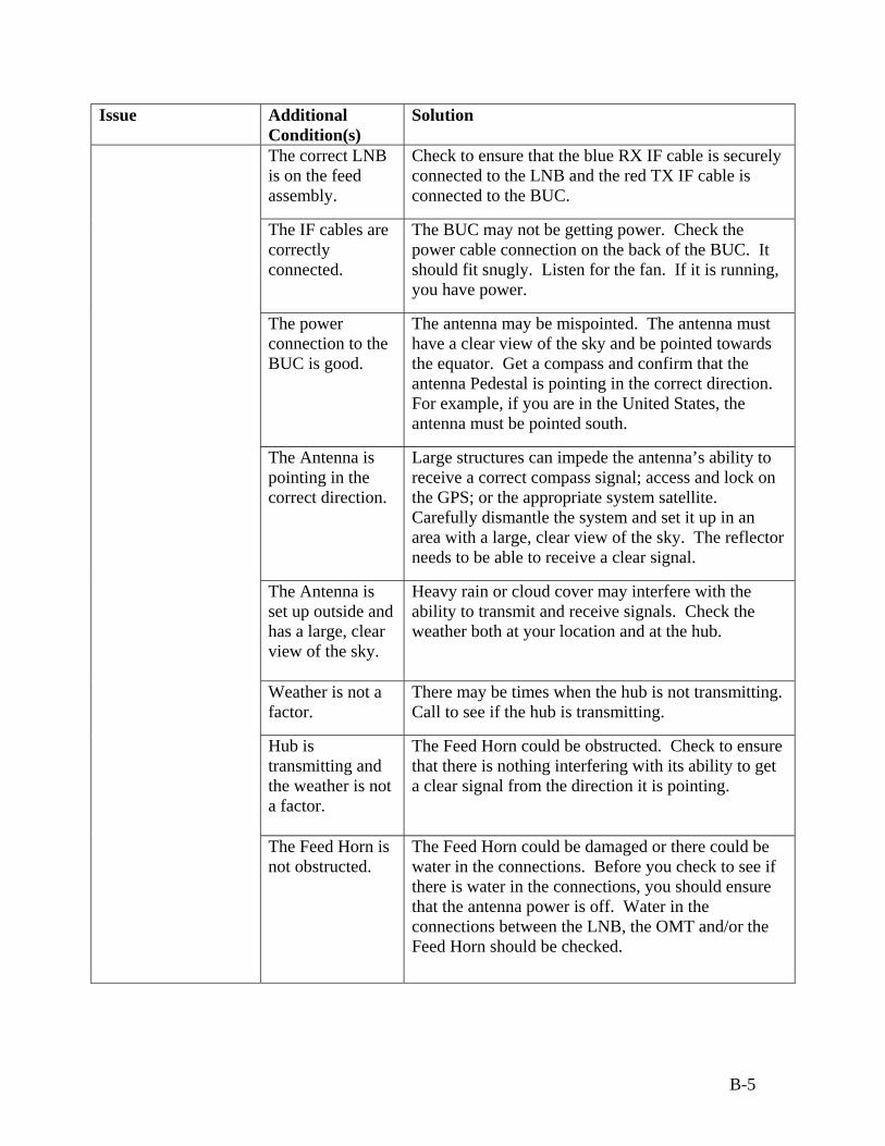
B-5
Issue Additional Condition(s)
Solution
The correct LNB is on the feed assembly.
Check to ensure that the blue RX IF cable is securely connected to the LNB and the red TX IF cable is connected to the BUC.
The IF cables are correctly connected.
The BUC may not be getting power. Check the power cable connection on the back of the BUC. It should fit snugly. Listen for the fan. If it is running, you have power.
The power connection to the BUC is good.
The antenna may be mispointed. The antenna must have a clear view of the sky and be pointed towards the equator. Get a compass and confirm that the antenna Pedestal is pointing in the correct direction. For example, if you are in the United States, the antenna must be pointed south.
The Antenna is pointing in the correct direction.
Large structures can impede the antenna’s ability to receive a correct compass signal; access and lock on the GPS; or the appropriate system satellite. Carefully dismantle the system and set it up in an area with a large, clear view of the sky. The reflector needs to be able to receive a clear signal.
The Antenna is set up outside and has a large, clear view of the sky.
Heavy rain or cloud cover may interfere with the ability to transmit and receive signals. Check the weather both at your location and at the hub.
Weather is not a factor.
There may be times when the hub is not transmitting. Call to see if the hub is transmitting.
Hub is transmitting and the weather is not a factor.
The Feed Horn could be obstructed. Check to ensure that there is nothing interfering with its ability to get a clear signal from the direction it is pointing.
The Feed Horn is not obstructed.
The Feed Horn could be damaged or there could be water in the connections. Before you check to see if there is water in the connections, you should ensure that the antenna power is off. Water in the connections between the LNB, the OMT and/or the Feed Horn should be checked.

B-6
Issue Additional Condition(s)
Solution
All connections are clear and the Feed Horn does not appear to be damaged.
The Rigid Waveguide cable could be damaged or there could be water in the connections. With the Antenna power and RF Equipment power switches on the Indoor Equipment set to off, remove the Rigid Waveguide and check the connections. Ensure that all are clear, dry and that the connections are once again tight.
All connections are clear and the rigid waveguide does not appear to be damaged.
Check the RX and TX IF cables at the Pedestal Base and back of the reflector. All connections should be tight.
All connections are good.
Once you have gone through all the other scenarios, the issue may be caused by internal hardware. You MUST contact the Network Management Center (NMC) before you attempt any further troubleshooting. • No 10 MHz reference or too low level • Bad BUC • Bad TX cable in chassis/antenna and internal to
antenna • Bad IDIRECT modem • Damaged Rigid Waveguide (not visibly)
Check for any obstructions *
Will not acquire GPS.
Check that the IFL cables are fully connected and color codes match. * Check for any obstructions *
Antenna will not find Reference Satellite.
Check that the Reference Satellite is loaded into the Antenna Controller Unit (ACU). * Check for any obstructions *
Check that the Data Satellite is loaded into the ACU.*
Antenna finds Reference Satellite but will not find Data Satellite.
Check to make sure you have selected the right Data Satellite. *

B-7
Issue Additional Condition(s)
Solution
Check to make sure the Reflector is pointed to the right Data Satellite. *
Check if the correct LNB is installed for the region. *
Check to see if the LNB is getting voltage. * Check that the IFL cables are fully connected and color codes match. *
Check continuity of the IFL cable. *
Check if feed pol is correct for region. *
Modem doesn’t receive lock.
If problem persists, it may be a bad LNB or Modem. *
Bad Modem The Network LED will be solid green if you have a working network connection. If it is not, then you have lost signal.
The network LED is green, but the internet connection is still down.
Check to ensure that all of your internet browser software settings are correct. You will need to call the NOC to verify the correct settings for your system. If the internet settings are incorrectly set, it can make it seem as though the network connection is down.
No Web Access.
The internet settings are correct.
Once you have gone through all the other scenarios, the issue may be caused by internal hardware. You MUST contact the Network Management Center (NMC) before you attempt any further troubleshooting. • Bad chassis cable to IP Switch • Bad chassis connections between modem and the
IP Switch • Bad chassis cable to Hub • Bad chassis connections between Hub and IP
Switch • Bad chassis cable to Port • Bad chassis connections between Hub and the
Port • Bad chassis cable to IP Switch • Bad chassis connections between Port and the
User switch

B-8
Issue Additional Condition(s)
Solution
• Bad chassis cable to User Switch • Bad switch • Bad Hub • No DC power to switch • No DC power to Hub • No AC power to switch • NO AC power to Hub • Bad power supply to switch • Bad power supply to Hub.
Software reports: Operating in unsupported Area.
The CSS SATCOM Global Network system is currently only supported in certain areas of the world. If you get this message, you will not be able to use the CSS VSAT system, until you return to a section of the world in which it is supported.
Internet connection was established, but has been lost.
If the antenna receives a bump or physical disturbance during operation, modem lock may be lost, which will shut down the transmit system. Weather may also cause the Internet connection to be lost. The satellite signal will need to be reacquired.
The Antenna has not been bumped or disturbed.
Temporary loss of power once the terminal is operational may cause the loss of communications with terminal components. The antenna will remain pointed, but will no longer track the satellite.
The NOC receives a terminal alarm.
If the CSS VSAT system is shutdown manually and not initiated through the laptop, notification of the terminal shut down is sent to the NOC. Inform the NOC of the incorrect shutdown of the system. The NOC may require you to set up the system again, for proper notification to be sent or may accept verbal notification.
The soft key needed on the VoIP phone does not appear on the display screen.
• Press the “More” soft key to reveal additional keys.
• Change the line state (for example, go off-hook or have a connected call).
• Check with your System Administrator to see if the phone is configured to support that soft key feature.

B-9
Issue Additional Condition(s)
Solution
Phone display remains blank.
• Phone is not receiving power. Check power supply.
Dialed number results in “fast busy”.
• Target phone is not on line.
Voice quality is poor. • Extreme network conditions may be causing interference. Hang up and try the same call again.
Voice is heard on one phone but not the other.
• A network malfunction is permitting voice traffic in only one direction. Try the same number on a different phone on the same CSS VSAT network.
• User may be attempting to use speaker phone. The 7911 and 7912 both have speakers, but not microphones.
Attempting to join multiple conference calls.
• When joining multiple conference calls be sure that you have selected at least one call in addition to the active call, which is selected automatically.
Accessing network configuration data.
When switching from one CSS VSAT system to another. The VoIP Phone IP has to be changed.
• Press the “Menu” button and select “Settings” scroll to “Network Configuration”.
• Select the network configuration item you want to view.
• Press “Cancel” to exit.
Accessing Status Data.
• Press the “Menu” button and select “Settings” scroll to “Status”.
• Select the network configuration item you want to view.
• Press “Cancel” to exit.
Accessing Phone Model information.
• Press the “Menu” button and select “Settings” scroll to “Model Information”.
• Use the “Navigation” button to scroll through and view model information for your phone.
• Press “Cancel” to exit.

B-10
Issue Additional Condition(s)
Solution
The soft key needed does not appear on the screen.
• Press the “More” soft key to reveal additional keys.
• Change the line state (for example, go off-hook or have a connected call).
• Check with your System Administrator to see if the phone is configured to support that soft key feature.
Phone display remains blank.
• Phone is not receiving power. Check power supply.
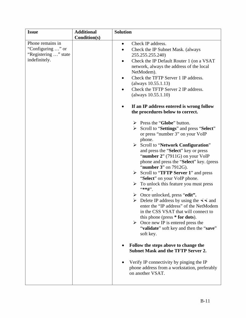
B-11
Issue Additional Condition(s)
Solution
Phone remains in “Configuring …” or “Registering …” state indefinitely.
• Check IP address. • Check the IP Subnet Mask. (always
255.255.255.240) • Check the IP Default Router 1 (on a VSAT
network, always the address of the local NetModem).
• Check the TFTP Server 1 IP address. (always 10.55.1.13)
• Check the TFTP Server 2 IP address. (always 10.55.1.10)
• If an IP address entered is wrong follow
the procedures below to correct.
Press the “Globe” button. Scroll to “Settings” and press “Select”
or press “number 3” on your VoIP phone.
Scroll to “Network Configuration” and press the “Select” key or press “number 2” (7911G) on your VoIP phone and press the “Select” key. (press “number 3” on 7912G).
Scroll to “TFTP Server 1” and press “Select” on your VoIP phone.
To unlock this feature you must press “**#”.
Once unlocked, press “edit”. Delete IP address by using the and
enter the “IP address” of the NetModem in the CSS VSAT that will connect to this phone (press * for dots).
Once new IP is entered press the “validate” soft key and then the “save” soft key.
• Follow the steps above to change the
Subnet Mask and the TFTP Server 2. • Verify IP connectivity by pinging the IP
phone address from a workstation, preferably on another VSAT.
B-12
Issue Additional Condition(s)
Solution
Dialed number results in “fast busy”.
• Target phone is not on line.
Voice quality is poor. • Extreme network conditions may be causing interference. Hang up and try the same call again.
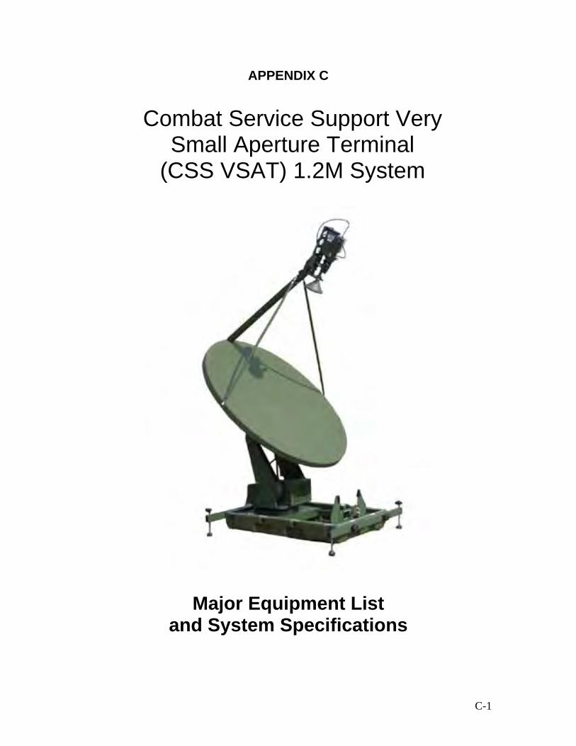
C-1
APPENDIX C
Major Equipment List and System Specifications
Combat Service Support Very Small Aperture Terminal
(CSS VSAT) 1.2M System

C-2
CSS VSAT 1.2M SYSTEM SPECIFICATIONS 1.2 Antenna
Reflector Size 1.2M Circular. Two piece Pedestal 3- Axis (Elevation over Azimuth) with polarization rotation Antenna Controller Fully automatic with internal GPS, Compass, and level
sensors. Handheld controller and manual Stow / Deploy switches provided.
Travel
Elevation Range 0-65° operational Azimuth Range ±200° from stow Polarization ±65° from center
Speed
Automatic 10° / second Azimuth. 5° / second Elevation Manual Jog 1.0° or 0.2° / second
RF Performance Receive Transmit Frequency Range 10.95 – 12.75 GHz 13.75 – 14.50 GHz Gain 42.2 dbi 43.6 dbi Beam Width (-3db) 1.3° 1.1° Beam Width (-10db) 2.2° 1.9° First Sidelobe -30 db -30 db Radiation pattern 29-25log θ 29-25log θ Figure of Merit 22.2 db/K typical EIRP 49.2 dbw max Polarization ` Linear Linear Cross-Pol On-Axis -35 db -40 db Off Axis -27 db -35 db Max -21 db -30 db
Tx/Rx Isolation 80 db

C-3
2.0 RF Equipment
Transmit
Frequency Range 14.0 – 14.5 GHz Output Power 6 dbw (1 db GCP) Spurious -50 dbc at rated power Third Order IMD -26 dbc at one half rated power Harmonics -50 dbc at 1 db GCP
Receive Frequency Range 10.95 – 11.70 GHz LNB #1
11.70 – 12.20 GHz LNB #2 12.25 – 12.75 GHZ LNB #3 3.0 VoIP Phone Equipment
Description Software Upgrades Software updates are downloaded from the Call
Manager using Trivial File Transfer Protocol (TFTP) Server.
Dimensions (H x W x D) 6.5x7x6 in. (20.3 x 17.67 x15.2 cm) Weight 1.9 1b (0.9 kg)
AC Region and County Specific Power Cords
CP-PWR-CORD-AP Asia Pacific CP-PWR-CORD-AR Argentina CP-PWR-CORD-AU Australia CP-PWR-CORD-CE European Community CP-PWR-CORD-CN China CP-PWR-CORD-JP Japan CP-PWR-CORD-NA North America CP-PWR-CORD-SW Switzerland CP-PWR-CORD-UK United Kingdom
VoIP Phone Temperature Ratings
Operating Temperature 32 to 104°F (0 to 40°C) Relative Humidity 10 to 95% (noncondensing) Storage Temperature 14 to 140°F (-10 to 60°C)
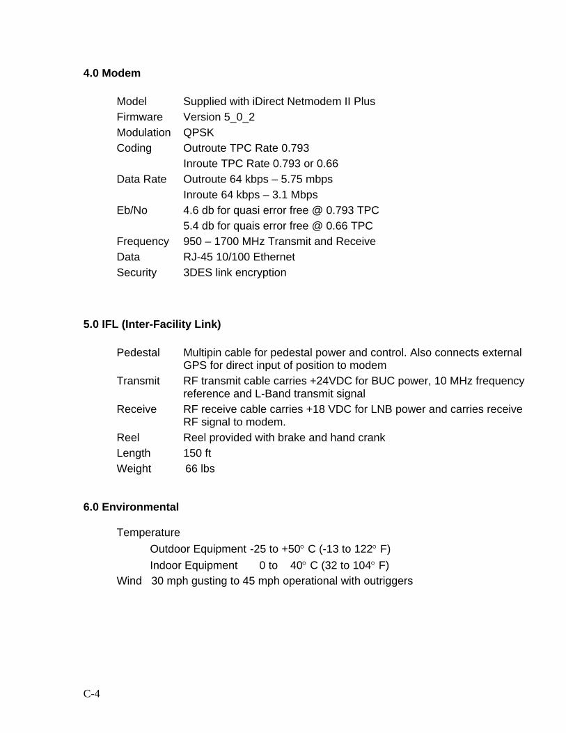
C-4
4.0 Modem Model Supplied with iDirect Netmodem II Plus Firmware Version 5_0_2 Modulation QPSK Coding Outroute TPC Rate 0.793
Inroute TPC Rate 0.793 or 0.66 Data Rate Outroute 64 kbps – 5.75 mbps
Inroute 64 kbps – 3.1 Mbps Eb/No 4.6 db for quasi error free @ 0.793 TPC
5.4 db for quais error free @ 0.66 TPC Frequency 950 – 1700 MHz Transmit and Receive Data RJ-45 10/100 Ethernet Security 3DES link encryption
5.0 IFL (Inter-Facility Link)
Pedestal Multipin cable for pedestal power and control. Also connects external GPS for direct input of position to modem
Transmit RF transmit cable carries +24VDC for BUC power, 10 MHz frequency reference and L-Band transmit signal
Receive RF receive cable carries +18 VDC for LNB power and carries receive RF signal to modem.
Reel Reel provided with brake and hand crank Length 150 ft Weight 66 lbs
6.0 Environmental
Temperature
Outdoor Equipment -25 to +50° C (-13 to 122° F) Indoor Equipment 0 to 40° C (32 to 104° F)
Wind 30 mph gusting to 45 mph operational with outriggers
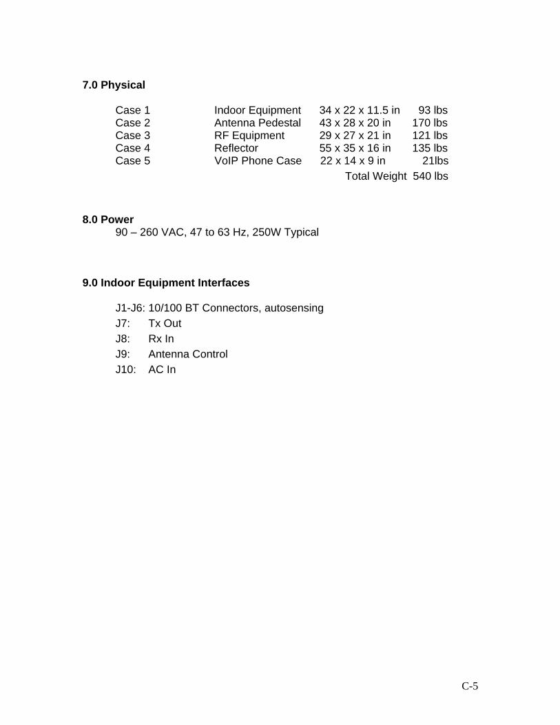
C-5
7.0 Physical
Case 1 Indoor Equipment 34 x 22 x 11.5 in 93 lbs Case 2 Antenna Pedestal 43 x 28 x 20 in 170 lbs Case 3 RF Equipment 29 x 27 x 21 in 121 lbs Case 4 Reflector 55 x 35 x 16 in 135 lbs Case 5 VoIP Phone Case 22 x 14 x 9 in 21lbs
Total Weight 540 lbs 8.0 Power 90 – 260 VAC, 47 to 63 Hz, 250W Typical 9.0 Indoor Equipment Interfaces
J1-J6: 10/100 BT Connectors, autosensing J7: Tx Out J8: Rx In J9: Antenna Control J10: AC In

C-6
CSS VSAT 1.2M SYSTEM MAJOR EQUIPMENT LIST Case 1: Indoor Equipment: P/N: 0056-1000-00 Item Part # Qty Description Comments
0056-1200-00 1 Modem Assembly
Includes iDirect™ Modem, Power Supply and Antenna Pedestal Power Supply.
0056-1300-00 1 Laptop Drawer Assembly
Includes Panasonic Toughbook CF50 laptop and drawer/slide assembly
110-SD208 1 Ethernet Switch 8-Port internal switch
0056-1700-00 1 Rear Panel I/O Assy Includes rear panel with all connectors and fans
Case 2: Antenna Pedestal: P/N: 0056-2000-00 Item Part # Qty Description Comments
64-12961 1 Antenna Pedestal
Includes hand crank and Outriggers.
0056-2100-00 1 Pedestal Control Box

C-7
Case 3: RF Equipment: P/N: 0056-3000-00 Item Part # Qty Description Comments
62-50174 1 4W BUC
66-2535S 1 LNB # 2, American Band
Installed on unit
66-2536S 1 LNB # 3, Intelsat Band
66-2537S 1 LNB # 1, European Band
65-360LA 1 Compass/Inclinometer
64-R7539 1 Ku-Band Feed Assembly
Padded canvas bag protects Feed Horn
77-R380S 1 Cable Reel
0056-3200-40 1 150 ft. IFL Cable Assy Includes Tx, Rx and control cables in a nylon sleeve.
Case 4: Reflector: P/N: 0056-4000-00 Item Part # Qty Description Comments
64-11398 1 1.2M Reflector Two-piece Reflector
20-34094 1 Antenna Feed Boom
20-34094 2 Antenna Feed Struts
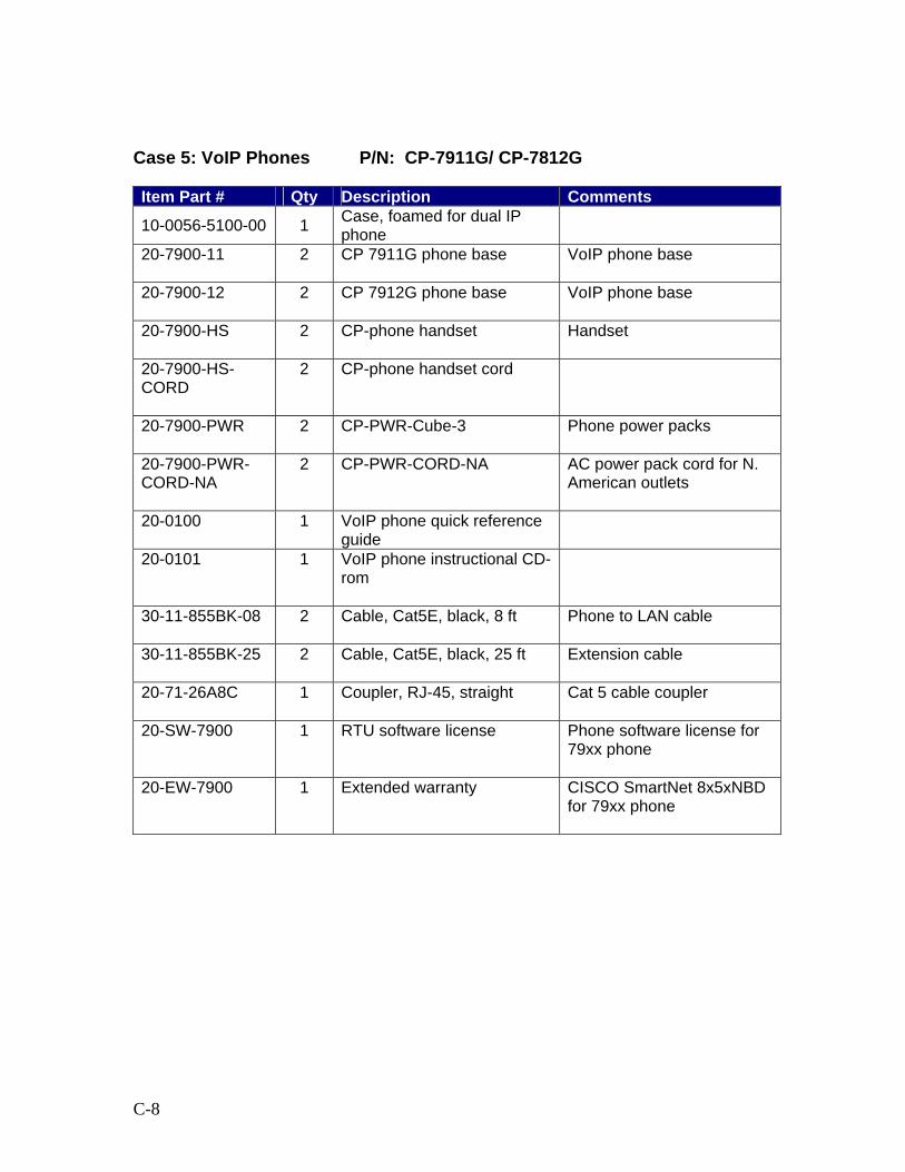
C-8
Case 5: VoIP Phones P/N: CP-7911G/ CP-7812G Item Part # Qty Description Comments
10-0056-5100-00 1 Case, foamed for dual IP phone
20-7900-11
2
CP 7911G phone base
VoIP phone base
20-7900-12
2
CP 7912G phone base
VoIP phone base
20-7900-HS
2
CP-phone handset
Handset
20-7900-HS-CORD
2
CP-phone handset cord
20-7900-PWR
2
CP-PWR-Cube-3
Phone power packs
20-7900-PWR-CORD-NA
2
CP-PWR-CORD-NA
AC power pack cord for N. American outlets
20-0100
1
VoIP phone quick reference guide
20-0101
1
VoIP phone instructional CD-rom
30-11-855BK-08
2
Cable, Cat5E, black, 8 ft
Phone to LAN cable
30-11-855BK-25
2
Cable, Cat5E, black, 25 ft
Extension cable
20-71-26A8C
1
Coupler, RJ-45, straight
Cat 5 cable coupler
20-SW-7900
1
RTU software license
Phone software license for 79xx phone
20-EW-7900
1
Extended warranty
CISCO SmartNet 8x5xNBD for 79xx phone
D-1
APPENDIX D
Articles
LandWarNet: Network of the Future Force
The U.S. Training and Doctrine Command is implementing its new backbone to prepare for the future of joint interoperability, integration, experimentation and training.
It seems every new initiative is heralded as something that will change the way we fight, but in LandWarNet’s case, that’s no exaggeration.
LandWarNet will be the backbone of every future force system or program and will be considered the Army’s network enterprise.
“If we’re to achieve decisive and rapid decision superiority in the future, we have to take a hard look at our command and control,” said General Kevin P. Byrnes, U.S. Army Training and Doctrine Command’s commanding general. “And one of the key areas—the most important program for the Army right now, aside from the soldier and fighting that last 400 meters—is getting the network right: networks, architectures, communications systems and applications to make that happen.”

D-2
LandWarNet will unify Army networks, from sustaining military bases to forward-deployed forces, fuse the Army’s efforts into the joint framework and optimize all elements of America’s combat power. As the Army shifts to modularity, with emphasis on smaller brigade-sized elements called “units of action,” battle command will decentralize but still be unified.
TRADOC’s role is to develop the requirements for LandWarNet’s operational aspects. Generally speaking, this is from the home-station operations center (HSOC) to the forward-deployed soldier.
“At all times—from peace through major combat operations to stability and peace-support operations—you must be able to operate in a real-time collaborative environment and with network-centric capabilities to achieve the asymmetric power we began to witness in Operation Iraqi Freedom,” noted Navy Admiral Edmund P. Giambastiani, commander of Joint Forces Command (JFCOM). JFCOM is charged with being the U.S. military’s joint forces provider, integrator and trainer, and with developing and experimenting joint concepts. In all these aspects, TRADOC and JFCOM partner together.
LandWarNet will integrate the Army’s information architecture and decentralize battle command. “LandWarNet is the ability to gain information that’s needed and get it to the unit that needs the knowledge so [the unit] can act on it before the enemy can act on what he’s acquiring,” Byrnes said. “Without the ability to have everyone in the loop, we don’t achieve what we wish to achieve, and then we fight as we’ve always fought. We will not be able to leverage the value of joint fires that could be obtained through a well-connected, networked joint force.”
While commanding the 1st Cavalry Division at Fort Hood, TX, five years ago, Byrnes commanded the Multinational Division (North) in Tuzla, Bosnia. He takes to heart lessons learned in the Balkans—and experiences dating back to the Vietnam War.
“In the past, we would take a large land force, line it up side by side, shoulder to shoulder, so it could talk to itself because comms were so limited,” Byrnes said. “We were designed to take on a force organized about the same way, and we developed our tactics to maneuver this force to gain advantage on the opponent. We don’t have to go on like this in the future if we’re plugged into the network, if we have communications that are reliable up and down the chain of command

D-3
with our joint partners, and if we have a clear vision of what the opponent is doing by being plugged into a sensor grid.
“We can see ourselves and have that situational understanding of how we are disposed and what the enemy is doing. Then, we have the forces that can be employed in a simultaneous distributed fashion across the battlespace, attacking nonlinearly instead of attacking side by side.”
Unifying Army Networks
“LandWarNet is the Army’s portion of the Global Information Grid [GIG], supporting users around the world,” explained Lieutenant General Steven W. Boutelle, the Army’s chief information officer/G-6. “LandWarNet provides networks to the active component forces, National Guard, Army Reserve and our sustaining and business base. This is all part of the Army transformation into joint, network-centric, interoperable, knowledge-based warfare.”
The Army’s network capabilities will continue to emerge and mature. LandWarNet will capture these emerging capabilities, encompassing the evolving “battle command” technologies, and link communications, information management and decision support.
A major element of LandWarNet will link deployed combatant commanders, land-component commanders and Joint Force commanders, who will provide the bridge between the deployed soldier and the GIG.
“We’re getting out of the staff-centric force we’ve had in the past, and we’re getting into a commander-centric force,” Byrnes said. “If we’re going to be interoperable, if we’re going to be joint, it begins with C4ISR [command, control, communications, computers, intelligence, surveillance and reconnaissance]. If you don’t have C4ISR interoperability across the joint force, you don’t have a coherent joint force. The absolute fundamental first effort that has to be accomplished [is] getting that interconnectivity of communications and intelligence.”
Another major element of LandWarNet will be the deployed soldier—soldiers, units of action/brigades, units of employment/division and corps elements in the deployed theater—where they will rely on mobile subscriber equipment for the time being. The Warfighter Information Network-Tactical (WIN-T) will replace current systems beginning in FY

D-4
2010. The Joint Tactical Radio System and the Future Combat System will also be integral parts of LandWarNet when they come on line. The Joint Command and Control System and Land Warrior will also be part of the net-centric battlespace.
“We’re going after the power of knowledge and networked forces: soldiers empowered, having knowledge of themselves, knowledge of the enemy; soldiers who see first, understand first and possess the ability to act first and finish decisively,” said Byrnes. “We have to invest in that. We have to invest in all the cutting-edge technologies that will get us longer ranges, more lethality, more survivability of our platforms, the ability to lighten what we have, to move it quicker and to reduce the size of the logistics tail that has to go along behind those forces.”
The future force will include joint task force capable units of employment; units of action with their mobile command groups; Marine Corps expeditionary forces; joint, allied and coalition networks; U.S. commercial networks; homeland defense networks; host nation agencies; civilian agencies; government agencies; non-government organizations; GIG services; special operations; and HSOCs. All these will feed into LandWarNet, providing Army connectivity and external-to-the-Army interoperability.
Under the LandWarNet umbrella, WIN-T will connect FCS vehicles beyond line-of-sight, providing the link between local groups of FCS vehicles to distant groups and connecting joint warfighting elements and C2 centers. WIN-T will also integrate the vehicle- and personnel-mounted JTRS to the satellite networks.
“FCS gets its lethality from the ability to move information around rapidly to understand where the enemy is and then engage the enemy at distance. If we can’t get the network right, all decisions we’ve made on the size and shape of [the future force] are invalid,” Byrnes said.
“Many of us are inclined to look at FCS as cannons [as] mobile gun systems. We’ve got to break that view. That view is not relevant because it’s the network’s centricity of that FCS that gives us the greatest degree of lethality and survivability. It’s the ability to see first, to understand first and to act first that allows us to finish decisively.”
As an example, Byrnes outlined an OIF commander’s situation. “[Lieutenant General William] Scott Wallace, the commander of V

D-5
Corps, had three channels to communicate with his force. Period. Three [satellite communications] channels … that’s it,” Byrnes said.
“Our lead forces had zero intelligence as they moved forward. They had tactical intelligence they developed through contact with the enemy, but the notion of a sensor grid at the tactical level was not there.
“We talk about a networked force and empowering the force with knowledge—it worked well [in OIF] at the higher echelons. The picture was much clearer; their ability to communicate data, voice and video was there. At the lower levels, where the fighting was conducted, we’re not there yet. We have an awful lot of work to do to push information and intelligence and connectivity to those lower levels, and that’s absolutely key to our force. If we’re to fight effectively and trade mass for knowledge, we’ve got to work the lower end, where the fighting occurs.”
Supporting Commanders
LandWarNet will support commanders, providing the infrastructure for battle command by enabling a network-centric information environment. LandWarNet will provide the means of distributing orders, managing battle command on the move, enabling on-demand collaboration and providing dependability and reachback to home station through the HSOC.
LandWarNet will free commanders from the traditional, static tactical command post since the communications network supporting the infosphere will be as mobile as the maneuver forces.
Commanders and leaders will have access to automated, collaborative decision-support tools to plan, synchronize and virtually rehearse missions no matter where they are in the battlespace. At the lower tactical echelons, commanders will be able to move with the same mobility as their soldiers.
“In Operation Iraqi Freedom, we saw the first glimpses of how the future force will fight,” Byrnes said. “Our commanders had situational awareness with a system called Blue Force Tracking. They were able to see their forces. They could communicate across the force and had a picture of the Blue Forces and where they were. That allowed us to execute simultaneously and with great speed.

D-6
“That simultaneity, rather than the sequential way we had gone to war in the past, gave us a speed we’ve never achieved before,” Byrnes said. “The forces that are going to deploy in the future will have the same survivability and lethality of heavy forces but can be employed anywhere on the battlefield. We want to get away from airfield requirements and port requirements and get into the unimproved [areas] and closer to key nodes and centers of gravity. We also want to move away from attrition-based campaigns to direct attack of key targets through the use of decision-superiority tools. We’re going to be able to protect the force better in the future by situational understanding and awareness.”
Joint Framework
LandWarNet is the counterpart to the Air Force’s ConstellationNet and the Navy’s FORCENet. The Army and Marine Corps are working jointly to develop a common land-component battle command system. All these battle command systems will come under the Joint Battle Management Command and Control process to integrate current and planned capabilities.
“What we really want is the ability to conduct land operations as part of the joint force: enter a theater at multiple points with smaller forces, with greater lethality, greater survivability, empowered by knowledge,” Byrnes said. “If [soldiers] know where they are and where all other Americans and allies are, and we know where the enemy is, we can get the sensor grid to tell us that, and [we] have the capability to plug into that sensor grid and pull down the information on where we’re seeing the enemy.
“Those smaller forces can fight as our forces do today with great courage and valor, and they will achieve their successes. And we’ll take [enemy forces] down rapidly, and this will be an Army force empowered by joint capabilities and empowered by knowledge. We believe that networked forces will be the way of the future ... [with a] smaller [and] lighter logistics footprint to get in early. This is not a World War II scheme of deployment into a theater with slow buildup and then application of ground. We’re talking about fighting upon arrival, not fighting after buildup. That’s what we seek in the future.
“It’s that synergy of joint operations—not interoperability or the combined effects—it’s the synergy of what you get from a joint team that trains together, that uses the same doctrine, that can network

D-7
together. You can get quantum leaps in lethality when you have that type of operation,” Byrnes said.
Keys to the Future
LandWarNet will give soldiers the keys to the future in decision superiority—increased situational awareness, plus more depth of information and greater speed of command—as well as battle command on the move access to joint capabilities and needed agility and flexibility for the future force soldier.
LandWarNet will ensure connectivity between joint forces and sister services down to the soldier. On future battlefields, soldiers must assimilate vast amounts of information, take what’s relevant and use it to their advantage in combat. The Army’s challenge is to provide soldiers the best capabilities to receive, process and transmit information, so the service is focusing this year on developing LandWarNet and network-centric battle command in general. Led by TRADOC’s Futures Center, in 2004, the Army will work on networked battle command and joint interoperability, integration, experimentation and training.

D-8
LandWarNet Equips Soldiers with Battlefield Information Just as Soldiers need the best equipment and training to be successful on the battlefield, a steady diet of information is just as vital, Army leaders believe. “Information is power,’’ said Brig. Gen. Jan Hicks, commanding general of the U.S. Army Signal Corps and Fort Gordon, Ga. “We want to know things about the battlefield and we want to know things about our enemy on the battlefield. At the same time, we don’t want the enemy to know what we know, or to know things about us.” Connecting Soldiers to information they need, whenever they need it and wherever they are, is the job of the Network, recently renamed LandWarNet. It’s one of 17 focus areas the Army is emphasizing to win the Global War on Terrorism. Hicks heads the task force assigned to make recommendations on how best to develop and improve LandWarNet so that it delivers better battle command capabilities to current, future, and joint forces. The joint aspect is of particular interest, Hicks said. “We’re not going to war as an Army. We’re going to war with our sailor and airmen friends,’’ Hicks said. “We must be able to communicate with them without an extra step. We need a system that allows one call.” Ultimately, the task force wants to see a LandWarNet that gives combatant commanders the same capabilities for accessing information in any location, whether that’s at a desktop computer in their office, in an aircraft, on a vessel at sea, in a vehicle en route to battle or in a post-battle camp, Hicks said. “We’re working on different ways to get there,’’ she added. One of those ways is through the Global Information Grid, or GIG. Hicks describes it as scaffolding built up around the globe. “Communication lines go all over, pulsing through the GIG,” she said.

D-9
“It services the defense information switch network, or DISN, which is provided by the Defense Information Services Agency.” Forces can reach into the DISN with satellites and pull information services down to wherever they are in the world, she explained. A combination of military and commercial technology powers LandWarNet, with leaders committed to pursuing programs that will enhance it even more. “Our current IT investment strategy is centered on leveraging the best available commercial technology,’’ said Col. James Costigan, director of Combat Development at the U.S. Army Signal Center. Leaders acknowledge that getting the network to the level the task force envisions is an expensive endeavor. Just how much is still being determined. “We’re talking about an almost clean sweep of the kind of equipment we have now,” Hicks said. “It will take a great deal of money to retool our networks while at war.” Many leaders believe the Army can’t afford not to make LandWarNet all it can be, however. “The application of information technology can enhance the efficiency and effectiveness of the processes involved in war fighting,’’ said Costigan. “Our experimentation with objective force concepts and our real-world experience in OIF shows us this notion is valid. Investing in IT systems to enable war fighting is therefore logical and necessary.”

D-10
THIS PAGE IS INTENTIONALLY LEFT BLANK

E-1
APPENDIX E CSS VSAT 1.2M System Equipment Checklist
Case Component/Contents Quantity Date 1. Indoor Equipment
iDirect Satellite Modem 1 Laptop 1 TracStar ACU 1 Reusable Fan Filters 8 2. Antenna Pedestal Antenna Pedestal 1 Hand Crank 1 Control Box 1 Outriggers 2 3. RF Equipment GFI / AC Power cord
Antenna Feed Horn Assembly w/ BUC, Antenna Feed Horn and LNB #2
1
Cable Reel, 150 ft. cable (TX, RX, and Power) 1
LNB # 1 1
LNB # 3 1
Compass/Inclinometer 1
Binder with Software CDRoms with Quick Reference Card and Satellite Card
1
Draft CSS VSAT 1.2M Operational Reference Guide
1
4. Reflector
2-piece 1.2M Antenna Reflector 1
Antenna Feed Boom 1
Antenna Feed Support Struts 2

E-2
Case Component/Contents Quantity Date
5. VoIP Phones
VoIP Phone 2
Handset 2
AC Power Cord 2
DC Power Supply 2
25 ft. CAT 5/6 Ethernet Cable 2
Footstand 2
8 ft. CAT 5/6 Ethernet 2
RJ-45 Coupler 2

APPENDIX F Quick CSS VSAT 1.2M System Assembly Procedures
F-1
1. Select suitable sites for the Indoor and Outdoor
Equipment Cases. 2. Place Indoor Equipment Case inside at the selected
operating area.
3. Place Antenna Pedestal, Reflector, and RF Equipment cases outdoors where the antenna will be deployed.
4. Open Antenna Pedestal Case and ensure the POWER
switch on the control box is set to OFF.
5. Remove the outriggers from the Antenna Pedestal Case Lid and attach to each end of the case. Turn the outrigger screws clockwise for firm contact with the ground.
6. Open the RF Equipment Case and remove the AC power
cord and IFL (Cable Reel) and set it on the floor within six feet of Indoor Equipment Case.
7. Remove Indoor Equipment Case Covers and mount on
each side of the (Indoor Equipment) Case.
8. At the Indoor Unit be sure that the AC breaker on rear panel and the ANTENNA and RF Equipment switches on the front panel are set to OFF; then connect the GFI/power cord to AC power connector on the rear panel and the other end into the AC power source.
9. Reset the GFI Switch.
10. On the IFL (Cable Reel) set the brake force adjustment to
soft or free. Unwind the cable as necessary to reach Antenna Pedestal Case at its outdoor position and place strain relief cable over the outrigger post.
11. At the control box connect the Power (ANTENNA), TX
(red) and RX (blue) connectors to the corresponding connectors on the panel in the base of the Antenna Pedestal Case.
12. At the IFL Cable Reel set the brake force adjustment
lever to lock and unwind the 6ft coiled section on the side of the reel.
13. Connect the Power (ANTENNA), TX (red) and RX
(blue) connectors to the corresponding connectors to the rear panel of Indoor Equipment Case.
14. Turn the AC circuit breaker and antenna power switch to on. Leave the RF power switch OFF.
15. At the antenna pedestal control box set the power switch
to ON (LED will illuminate).
16. Press and hold the DEPLOY/STOW switch to the DEPLOY position for 3 seconds or until the pedestal arm starts to move. (The antenna pedestal rises to a position for reflector mounting, approximately one minute).
17. Set the POWER switch on the control box to OFF.
18. Remove the antenna reflector halves from the Reflector
Case. Assemble the reflector using the three quick release levers.
19. Lay the assembled antenna reflector face up on a flat,
clean surface (i.e. reflector case/lid).
20. Remove and attach the antenna feed boom to the reflector, tightening the center captive thumbscrew only.
21. Attach the feed struts (2ea) from the reflector to the boom
using the friction-fit ball and socket connections.
22. Tighten left and right captive thumb screws on the antenna feed boom.
23. Remove the feed horn assembly from the RF Equipment
Case and verify the correct LNB is installed and the feed horn is properly polarized.
24. Connect the feed horn assembly to the feed boom using
the captive thumbscrew. On the feed horn assembly, connect the red cable to the BUC and the blue cable to the LNB.
25. Remove the protective feed horn cover and store it. 26. Set the assembled reflector onto the pedestal such that it
is supported by the bottom edge of the mounting wedge. Secure the reflector in place using the four 1/4-turn fasteners.
27. Connect the BUC, LNB, GPS and compass cables from
the rear of the feed boom to the cables from the pedestal. (Follow color coding). Wrap the cables around the support bracket on the back of the reflector to secure.
CAUTIONS • The CSS VSAT 1.2 Meter Systems weighs
approximately 540 pounds. • Use safe lift and carry procedures when handling
the cases. Each case may require up to a two- person lift and carry.
• Keep cases closed and latched when not accessing equipment to minimize the possibility of injury or snagging clothing.
• Do not connect or disconnect cables with power applied.
Turn to page 2-20 to begin the acquisition process.

APPENDIX F Quick CSS VSAT 1.2M System Disassembly Procedures
F-2
1. Using the VSAT notebook, on the Setup Tab click
Shutdown button to perform a soft shutdown. (refer to page 5-2 performing a Soft System Shutdown procedures).
2. Follow prompts – turn off RF Power Switch.
3. Close ViewSAT.
4. Close all open programs.
5. Shutdown and Turn off VSAT notebook.
6. Close and secure laptop.
7. Once the pedestal arm stops moving, set Antenna POWER
switch to OFF at the control box. This removes power to the pedestal and the second source of power to the LNB.
8. Unwrap and disconnect the BUC, LNB, GPS and compass
cables from the rear of the antenna. (Replace protective caps).
9. Remove assembled antenna reflector and place on a flat,
clean surface.
10. On the feed horn assembly, disconnect the red cable to the BUC and the blue cable to the LNB.
11. Replace the protective cover over the antenna feed horn
and set polarization for storage (if necessary).
12. Unscrew the captive thumbscrew between the antenna feed horn assembly and the antenna feed boom and remove the antenna feed horn assembly from the boom.
13. Carefully place the antenna feed horn assembly in the RF
Equipment Case.
14. Disconnect the two struts and carefully turn the three thumbscrews counterclockwise to loosen the feed boom from the antenna reflector.
15. Carefully place the feed boom and struts in the Reflector
case.
16. Disassemble antenna reflector and repack into Reflector Case. (lower half goes in first). Attach lid on Reflector case and secure latches.
17. At the antenna control box set Antenna POWER switch to ON, press and hold DEPLOY/STOW switch to STOW for 3 seconds or until the antenna pedestal starts to move. (Power should be On at Indoor Equipment Case at this time)
18. Once the pedestal arm stops moving, set the POWER
switch to OFF on pedestal control box.
19. At the Indoor equipment case set the ANTENNA switch to OFF.
20. Set the AC breaker on the rear of the Indoor Equipment
Case to OFF.
21. Disconnect the Antenna POWER cable Transmit (Tx) cable and Receive (Rx) cable from the control box (replace protective caps).
22. Remove outriggers and secure in lid. Attach lid on
Antenna Pedestal Case and secure latches.
23. Disconnect the protective caps and the antenna POWER, Transmit (Tx) cable and Receive (Rx) cable from the rear panel of Indoor Equipment (replace protective caps).
24. Wind the indoor 6ft section of IFL cable onto the side of
the reel, and then wind the used outdoor length onto the reel. Place the reel in RF Equipment Case.
25. Disconnect AC power cable from Indoor Equipment Case
and place in RF Equipment Case, attach lid and secure latches.
26. Disconnect all input / user cables and attach Indoor
Equipment Case end covers and secure latches.
CAUTIONS • The CSS VSAT 1.2 Meter Systems weighs
approximately 540 pounds. • Use safe lift and carry procedures when handling
the cases. Each case may require up to a two- person lift and carry.
• Keep cases closed and latched when not accessing equipment to minimize the possibility of injury or snagging clothing.
• Do not connect or disconnect cables with power applied.