CHAPTER-1 INTRODUCTION - Shodhgangashodhganga.inflibnet.ac.in/bitstream/10603/48048/11... ·...
31
CHAPTER-1 INTRODUCTION
Transcript of CHAPTER-1 INTRODUCTION - Shodhgangashodhganga.inflibnet.ac.in/bitstream/10603/48048/11... ·...

CHAPTER-1
INTRODUCTION
Chapter 1 Introduction
1
CHAPTER 1
INTRODUCTION
1.1 PREAMBLE
Materials science is a significant research area in our present society, and our continuous
technological development is depending on new and improved materials with suitable
properties. In the search of novel materials with the required qualities, it is important to
understand the relationship between synthesis, atomic scale structure and bulk properties.
The physical properties of many technologically relevant ceramic materials such as
electrical, magnetic, elastic, optical etc. are strongly influenced by their crystal structure,
microstructure and electronic structure. Research and development on dielectric materials
in the form of single crystals, ceramics (bulk and nano) and thin films have been closely
related to industrial needs in electrical/radio technology, telecommunications, computing,
defense, aerospace, microelectronics, laser technology, microwave applications, transducer,
actuators, computer memory, electo-optical modulator, light valves etc. The field of
dielectric materials is broadly divided into linear and nonlinear dielectric (ferroelectric,
anti-ferroelectric, piezoelectric, pyro-electric and multi-ferroic materials). To achieve rich
multifunctionality, one of the very promising approaches is to create novel materials by
modifying or combining different physical properties in the same material or phase.
1.2 FERROIC MATERIAL:
Ferroics are functional materials whose physical properties are sensitive to changes in
external conditions such as temperature, pressure, electric and magnetic fields. A ferroic
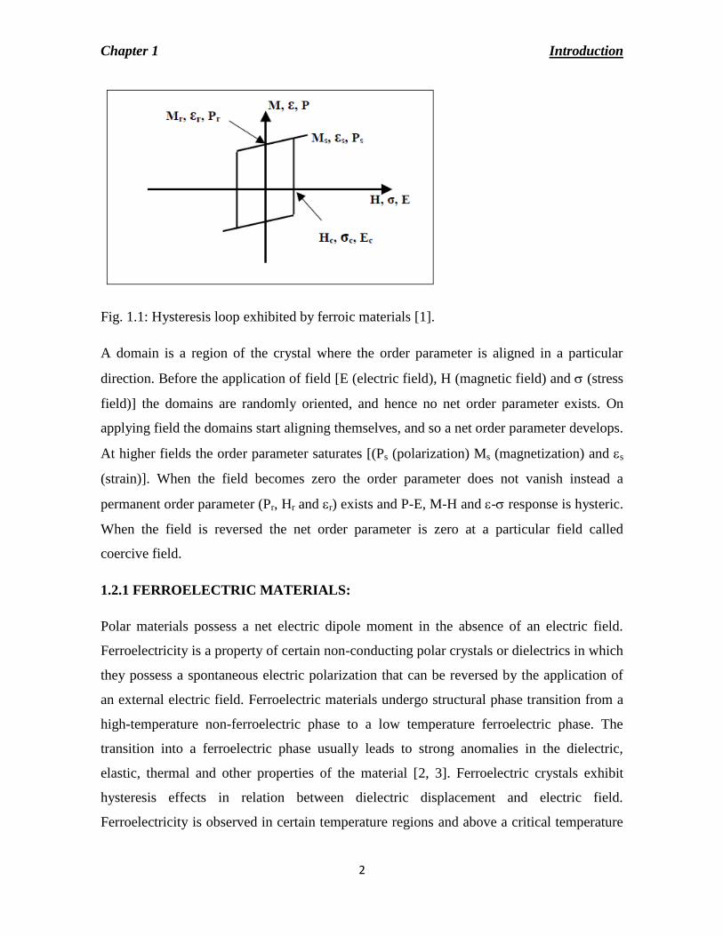
material exhibits ferroelectricity, ferromagnetism or ferroelastic ordering. Fig.1 shows a
well-defined hysteresis loop when the material is switched electrically, magnetically or
mechanically. The properties of ferroic materials are often superior to conventional
materials because of their spontaneous order parameters and large non-linear coefficients.
Because of these properties they can be widely used for sensors and actuators. Ferroic
materials usually undergo a phase transition from non-ferroic to ferroic state.
Chapter 1 Introduction
2
Fig. 1.1: Hysteresis loop exhibited by ferroic materials [1].
A domain is a region of the crystal where the order parameter is aligned in a particular
direction. Before the application of field [E (electric field), H (magnetic field) and (stress
field)] the domains are randomly oriented, and hence no net order parameter exists. On
applying field the domains start aligning themselves, and so a net order parameter develops.
At higher fields the order parameter saturates [(Ps (polarization) Ms (magnetization) and s
(strain)]. When the field becomes zero the order parameter does not vanish instead a
permanent order parameter (Pr, Hr and r) exists and P-E, M-H and - response is hysteric.
When the field is reversed the net order parameter is zero at a particular field called
coercive field.
1.2.1 FERROELECTRIC MATERIALS:
Polar materials possess a net electric dipole moment in the absence of an electric field.
Ferroelectricity is a property of certain non-conducting polar crystals or dielectrics in which
they possess a spontaneous electric polarization that can be reversed by the application of
an external electric field. Ferroelectric materials undergo structural phase transition from a
high-temperature non-ferroelectric phase to a low temperature ferroelectric phase. The
transition into a ferroelectric phase usually leads to strong anomalies in the dielectric,
elastic, thermal and other properties of the material [2, 3]. Ferroelectric crystals exhibit
hysteresis effects in relation between dielectric displacement and electric field.
Ferroelectricity is observed in certain temperature regions and above a critical temperature
Chapter 1 Introduction
3
known as transition (or Curie) temperature the crystals are no longer ferroelectric, and
exhibit normal dielectric behavior [4]. Ferroelectric materials are technologically an
important class of materials that display a wide variety of phenomena, and hence have wide
applications such as non-volatile ferroelectric random access memories, sensors, actuators,
high dielectric constant capacitors, radio and communication filters, piezoelectric sonar,
ultrasonic transducers, ultrasonic motors, etc. Ferroelectricity was first discovered in
Rochelle salt (a double tartarate of sodium and potassium crystallizing with 4 molecules of
water, NaKC4H4O6. 4H2O) in 1920 [5]. At present large number of structural families of
ferroelectrics are known. The natural state of a ferroelectric material is a multi-domain
state. When electric field is applied the domain walls will reduce (in ceramics) or is
completely removed (in crystals). Occurrence of the ferroelectric hysteresis loop is one of
the consequences of domain wall switching in ferroelectric materials.
1.2.1 (A) CLASSIFICATION OF FERROELECTRICS:
Based on chemical composition and crystal structure, ferroelectrics are classified into four
categories:
(a) Tartarate group: Rochelle salt (NaKC4H4O6. 4H2O) is an example of this group [5].
(b) KDP: This is the example of dihydrogen phosphate of alkali metal [6].
(c) Oxygen octahedral group: This group has four different structures:
(i) Perovskite-type
(ii) Tungsten-bronze type
(iii) Layer structure oxides and complex compounds
(iv) Pyroclore-type ferroelectrics
(d) Ganidine aluminium hexahydrate NHC (NH2)2AlH(SO4)210H2O
1.2.1 (B) PEROVSKITE FERROELECTRICS:
Among ferroelectric oxides the family of oxygen octahedral consisting of one or more
component oxides is one of the most important group. Among all the ferroelectric
materials, perovskites are the most widely and extensively studied and used. A perfect
perovskite structure can be represented by a general formula as ABO3 where A is a large
Chapter 1 Introduction
4
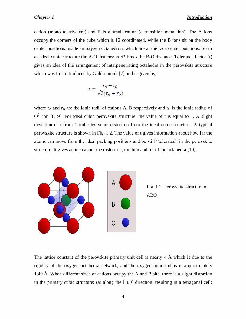
cation (mono to trivalent) and B is a small cation (a transition metal ion). The A ions
occupy the corners of the cube which is 12 coordinated, while the B ions sit on the body
center positions inside an oxygen octahedron, which are at the face center positions. So in
an ideal cubic structure the A-O distance is √2 times the B-O distance. Tolerance factor (t)
gives an idea of the arrangement of interpenetrating octahedra in the perovskite structure
which was first introduced by Goldschmidt [7] and is given by,
where rA and rB are the ionic radii of cations A, B respectively and rO is the ionic radius of
O2-
ion [8, 9]. For ideal cubic perovskite structure, the value of t is equal to 1. A slight
deviation of t from 1 indicates some distortion from the ideal cubic structure. A typical
perovskite structure is shown in Fig. 1.2. The value of t gives information about how far the
atoms can move from the ideal packing positions and be still “tolerated” in the perovskite
structure. It gives an idea about the distortion, rotation and tilt of the octahedra [10].
Fig. 1.2: Perovskite structure of
ABO3.
The lattice constant of the perovskite primary unit cell is nearly 4 Å which is due to the
rigidity of the oxygen octahedra network, and the oxygen ionic radius is approximately
1.40 Å. When different sizes of cations occupy the A and B site, there is a slight distortion
in the primary cubic structure: (a) along the [100] direction, resulting in a tetragonal cell;
Chapter 1 Introduction
5
(b) along the [110] direction, leading to an orthorhombic cell, (c) along the [111] direction,
giving rise to a rhombohedral cell, or (d) along arbitrary [hkl] directions, producing
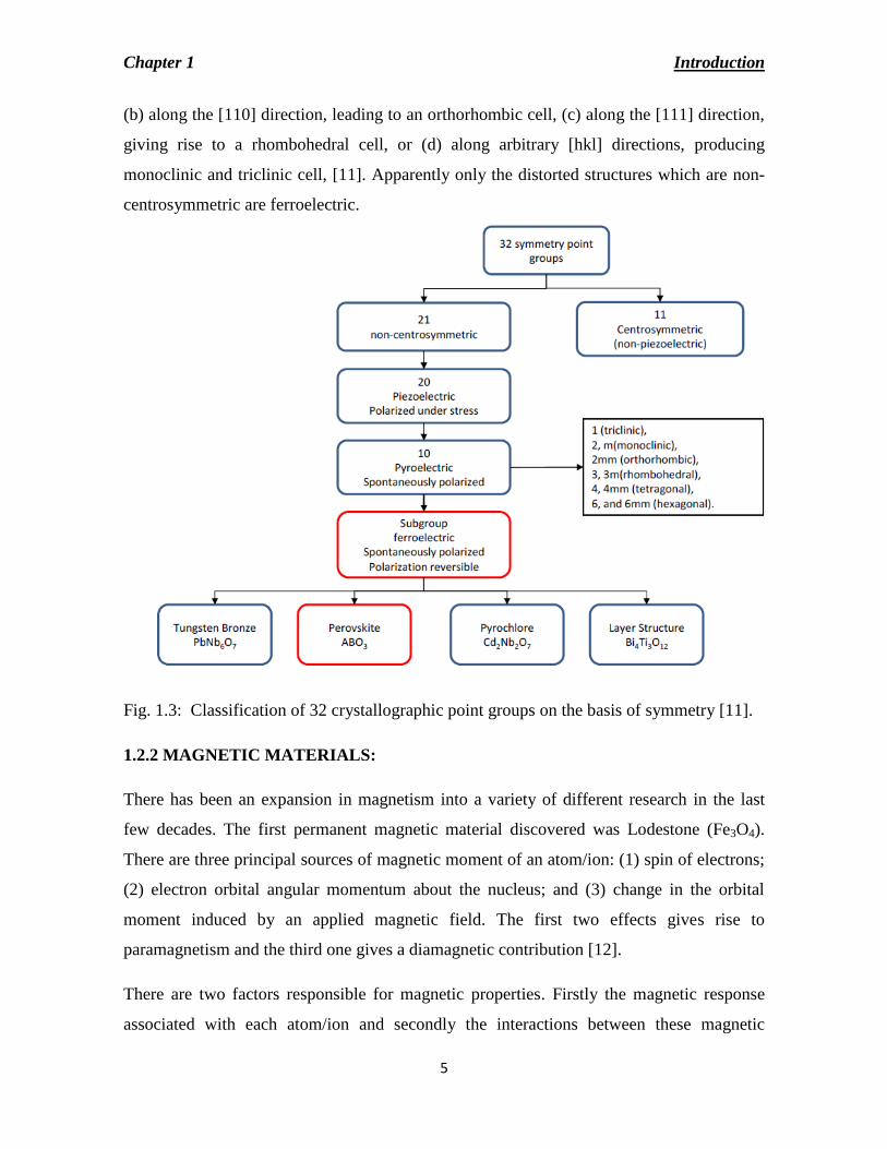
monoclinic and triclinic cell, [11]. Apparently only the distorted structures which are non-
centrosymmetric are ferroelectric.
Fig. 1.3: Classification of 32 crystallographic point groups on the basis of symmetry [11].
1.2.2 MAGNETIC MATERIALS:
There has been an expansion in magnetism into a variety of different research in the last
few decades. The first permanent magnetic material discovered was Lodestone (Fe3O4).
There are three principal sources of magnetic moment of an atom/ion: (1) spin of electrons;
(2) electron orbital angular momentum about the nucleus; and (3) change in the orbital
moment induced by an applied magnetic field. The first two effects gives rise to
paramagnetism and the third one gives a diamagnetic contribution [12].
There are two factors responsible for magnetic properties. Firstly the magnetic response
associated with each atom/ion and secondly the interactions between these magnetic
Chapter 1 Introduction
6
moments. Around each atom/ion there is no unpaired electron. This results in net zero
magnetic moment and the hence the material will show diamagnetic behavior. Depending
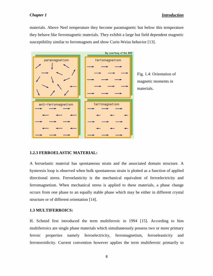
on the interactions between the magnetic dipoles, the materials exhibit (i) paramagnetism;
(ii) ferromagnetism; (iii) antiferromagnetism and (iv) ferrimagnetism.
(A) DIAMAGNETIC MATERIALS:
When a material is placed in a magnetic field, the electrons in the atomic orbitals move in
such a way so as to oppose the magnetic field by inducing a magnetic moment and the
direction of the induced dipole moment is opposite to that of the external field. This effect
is known as diamagnetism. The induced dipole moment disappears on removal of external
field. Materials with closed electron subshells exhibit diamagnetism. Thus, diamagnetic
materials do not have a permanent magnetic moment, and by themselves are not useful in a
wide range of magnetic applications. The relative permittivity is less than unity which
means the magnetic susceptibility is negative and is of the order of -10-5
. Because of this
the material gets weakly repelled in the magnetic field. Materials such as copper, silver,
silicon, gold, zinc and alumina are diamagnetic at room temperature [13].
(B) PARAMAGNETIC MATERIALS:
In certain materials, due to incomplete cancellation of electron spin each atom or molecule
possesses permanent magnetic moment. In the absence of an external field these atomic
magnetic moments are randomly oriented and hence the materials possess no net
magnetization. But when an external magnetic field is applied, the individual magnetic
moment tends to align themselves in the direction of the field which gives rise to non-zero
magnetization. Thermal agitation disturbs the alignment of the magnetic moment and so at
higher temperatures, greater fields are required to attain the same magnetization. When the
magnetic field is removed the effect vanishes. These materials have relative permittivity
greater than unity and have small positive susceptibility which ranges between 10-5
- 10-2
.
The temperature dependence of paramagnetic susceptibility is described by the relation, χ =
C/T. This is the Curie law of paramagnetism where C is the Curie constant. Examples of
such materials are aluminium, chromium, sodium, titanium, zirconium alloys of copper
[13].

Chapter 1 Introduction
7
(C) FERROMAGNETIC MATERALS:
In these materials due to parallel alignment of adjacent magnetic spins a large net magnetic
moment exists. Due to uncancelled electron spins ferromagnetic materials possess
permanent magnetic moments. In comparision to the spin moment orbital magnetic moment
contribution is quite small. Even in the absence of an externally applied magnetic field
mutual spin alignment exists over large volume regions of the crystal called domains and
hence possess permanent magnetizations with a positive magnetic susceptibility. A largely
nonlinear relationship exists between the externally applied magnetic field μH and the
magnetization M, and at very high magnetic fields (depending on the material) the
magnetization M saturates, called the saturation magnetization Ms. When the magnetic field
reduces to zero, the material has a remnant magnetization Mr. Further reducing the applied
field below zero causes the magnetization M to eventually reach zero, reaching the coercive
field Hc at M = 0.
The temperature above which materials lose ferromagnetism and become paramagnetic is
called Curie temperature (Tc). With many ferromagnetic materials in the paramagnetic
phase, the susceptibility of the material, χ, is governed by the Curie – Weiss law, namely,
χ = 𝐶
𝑇−𝑇𝑐
(D) ANTIFERROMAGNETIC MATERALS:
In an antiferromagnetic material no net magnetic moment exists due to antiparallel
alignment of magnetic spins. At absolute zero antiferromagnets exhibit diamagnetism.
Exchange interaction causes parallel alignment of spins which is very sensitive to
interatomic spacing and to the atomic positions. This sensitivity causes anti-parallel
alignment of spins. These materials attain maximum susceptibility at a critical temperature
called Neel temperature above which they become paramagnetic [13].
(E) FERRIMAGNETIC MATERALS:
Ferrimagnetism is a special case of antiferromagnetism where the material consists of
antiparallel spins of different magnitudes. As the adjacent spins are of different magnitudes,
even in the absence of an applied magnetic field a net magnetic moment exists in these
Chapter 1 Introduction
8
materials. Above Neel temperature they become paramagnetic but below this temperature
they behave like ferromagnetic materials. They exhibit a large but field dependent magnetic
susceptibility similar to ferromagnets and show Curie-Weiss behavior [13].
Fig. 1.4: Orientation of
magnetic moments in
materials.
1.2.3 FERROELASTIC MATERIAL:
A ferroelastic material has spontaneous strain and the associated domain structure. A
hysteresis loop is observed when bulk spontaneous strain is plotted as a function of applied
directional stress. Ferroelasticity is the mechanical equivalent of ferroelectricity and
ferromagnetism. When mechanical stress is applied to these materials, a phase change
occurs from one phase to an equally stable phase which may be either in different crystal
structure or of different orientation [14].
1.3 MULTIFERROICS:
H. Schmid first introduced the term multiferroic in 1994 [15]. According to him
multiferroics are single phase materials which simultaneously possess two or more primary
ferroic properties namely ferroelectricity, ferromagnetism, ferroeleasticity and
ferrotoroidicity. Current convention however applies the term multiferroic primarily to

Chapter 1 Introduction
9
materials that combine ferroelectricity with ferromagnetism or with any kind of magnetism
(antiferromagnetism) (Fig. 1.5). One of the most appealing aspects of multiferroics is
magnetoelectric coupling. In a magnetoelectric effect, a magnetic field can tune the electric
polarization and an electric field can tune the magnetization.
Fig. 1.5: Schematic illustration
of multiferroic defined from
the combination of
ferroelectric and magnetic
properties [16].
Due to the coupling between ferroelectric and ferromagnetic ordering, multiferroics have a
wide range of applications in spintronics, multiple state memory, data storage media,
sensor, tunable microwave devices etc. [17-19].
Multiferroics usually belong to the group of the perovskite transition metal oxides. They
also include rare-earth manganites and -ferrites (e.g. TbMnO3, HoMn2O5, LuFe2O4 and
recently, PZTFT). Other examples are bismuth compounds (such as BiFeO3 and BiMnO3),
and non-oxides such as BaNiF4 and spinel chalcogenides (ZnCr2Se4). Nickel iodine
boracite (Ni3B7O13I) was the first discovered multiferroic material that was simultaneously
ferroelectric and ferromagnetic [20]. Subsequently various types of studies were made on
many boracite compounds. As most of them have quite complex structures, they were not
very useful from technological point of view. This is followed by studies on mixed
perovskites, essentially solid solutions of two perovskite- oxides. Lot of investigations was
done by Russian scientists. They replaced some of the d0 type cations in the ferroelectric
Chapter 1 Introduction
10
perovskite oxides with magnetic dn type elements in order to induce magnetic ordering in
them. Solid solution of Pb(Fe2/3W1/3)O3 and Pb(Mg1/2W1/2)O3 was one of such compounds
first discovered. However, most of these materials have very low Curie temperatures or
Neel temperature which prevents further research on these. There are many requirements
which need to be fulfilled for a material to be multiferroic. For ferroelectricity, a material
must be non-centrosymmetric to possess spontaneous electrical polarization. Out of 32
point groups 11 are centrosymmetric and hence do not allow a unique polar direction. Of
these 21 classes 20 are piezoelectric and of these 20 classes 10 have unique polar axis and
hence exhibit ferroelectricity. Similarly, spontaneous magnetic moment is permitted by 31
point groups. Out of these 13 point groups allow occurrence of both the properties
simultaneously. Since this is not a small number, it is probably unlikely that symmetry
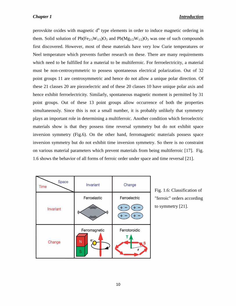
plays an important role in determining a multiferroic. Another condition which ferroelectric
materials show is that they possess time reversal symmetry but do not exhibit space
inversion symmetry (Fig.6). On the other hand, ferromagnetic materials possess space
inversion symmetry but do not exhibit time inversion symmetry. So there is no constraint
on various material parameters which prevent materials from being multiferroic [17]. Fig.
1.6 shows the behavior of all forms of ferroic order under space and time reversal [21].
Fig. 1.6: Classification of
"ferroic" orders according
to symmetry [21].
Chapter 1 Introduction
11
1.3.1 CLASSIFICATION OF MULTIFERROICS:
According to the origin of magnetic and ferroelectric ordering multiferroics are classified
into:
(i) Type I multiferroics:
In this group of multiferroics ferroelectricity and magnetism have different sources and
appear largely independently of one another. A weak coupling between ferroelectricity and
magnetism is observed. In these materials, ferroelectricity is usually observed at higher
temperatures than magnetism and the spontaneous polarization (P) is quite large. Examples
are BiFeO3 (TC = 1100K, TN = 643K, P = 90 μC/cm2) and YMnO3 (TC = 914K, TN = 76K,
P= 690 μC/cm2). One of the ways to achieve both magnetism and ferroelectricity in a single
phase perovskite is by partially substituting d0 ion with magnetic ion at the B-site. As
different ions are involved in magnetism and ferroelectricity the magnetoelectric coupling
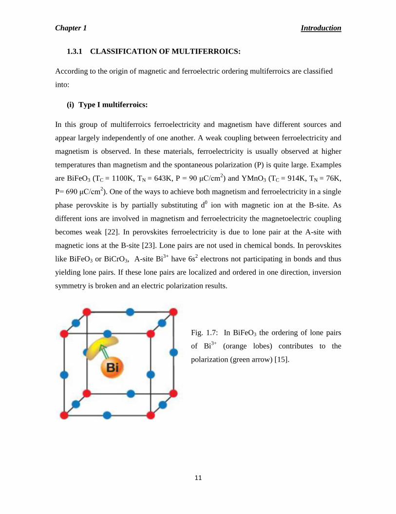
becomes weak [22]. In perovskites ferroelectricity is due to lone pair at the A-site with
magnetic ions at the B-site [23]. Lone pairs are not used in chemical bonds. In perovskites
like BiFeO3 or BiCrO3, A-site Bi3+
have 6s2 electrons not participating in bonds and thus
yielding lone pairs. If these lone pairs are localized and ordered in one direction, inversion
symmetry is broken and an electric polarization results.
Fig. 1.7: In BiFeO3 the ordering of lone pairs
of Bi3+
(orange lobes) contributes to the
polarization (green arrow) [15].

Chapter 1 Introduction
12
(ii) Type-II multiferroics:
In this type of multiferroics a particular type of magnetic spiral or even for collinear
magnetic structures causes ferroelectricity. This implies a strong coupling between the two.
But the polarization in these materials is usually very small and the ferroelectricity usually
appears at low temperatures [24, 25]. Examples of such type of materials are TbMnO3,
Ni3V2O8, MnWO4 etc.
(a) Spiral type-II multiferroics:
Most of the type-II multiferroics belong to this subgroup, and it is usually found in
frustrated systems, where ferroelectricity and antiferromagnetism co-exist with very strong
coupling. The ferroelectricity appears with conjuction with a spirally magnetic phase,
mostly cycloidal type. Examples of such type of multiferroics are TbMnO3, Ni3V2O8, and
MnWO4. A spin chain with a ferromagnetic interaction (FM) J' > 0 between the
neighbouring spins has uniform ground state with all spins parallel. An antiferromagnetic
(AFM) next neighbor interaction J < 0 frustrates this simple ordering. Like any other
magnetic ordering, the magnetic spiral spontaneously breaks time-reversal symmetry. In
addition it breaks inversion symmetry, because the change of the sign of all coordinates
inverts the direction of the rotation of spins in the spiral. Thus the symmetry of the spiral
state allows for a simultaneous presence of electric polarization [26].
Fig. 1.8: Frustrated spin chains with the nearest neighbor FM and next nearest neighbor
AFM interactions J and J' (Figure adopted from [24])
(b) Type-II multiferroics with collinear magnetic structures:
In such type of multiferroics the magnetic moments are aligned in a particular axis without
the involvement of the spin-orbit interaction. Variation of magnetic coupling with atomic
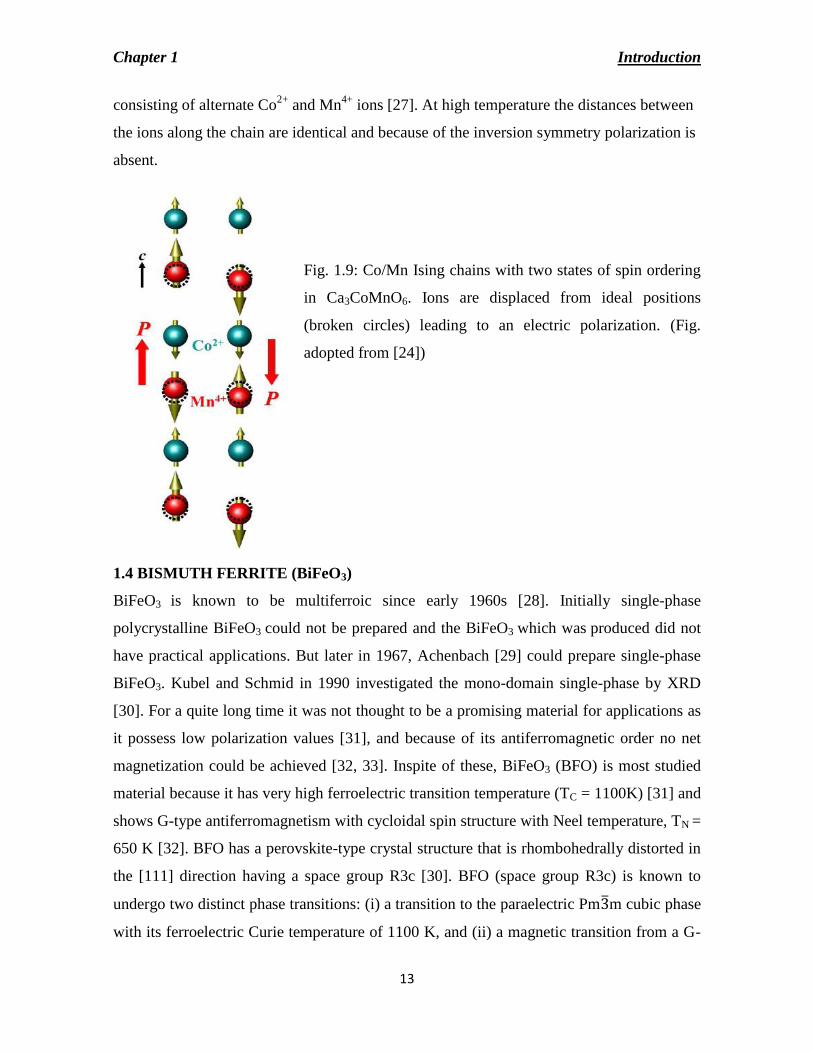
positions causes polarization in these multiferroics. One of such example is in Ca3CoMnO6
Chapter 1 Introduction
13
consisting of alternate Co2+
and Mn4+
ions [27]. At high temperature the distances between
the ions along the chain are identical and because of the inversion symmetry polarization is
absent.
Fig. 1.9: Co/Mn Ising chains with two states of spin ordering
in Ca3CoMnO6. Ions are displaced from ideal positions
(broken circles) leading to an electric polarization. (Fig.
adopted from [24])
1.4 BISMUTH FERRITE (BiFeO3)
BiFeO3 is known to be multiferroic since early 1960s [28]. Initially single-phase
polycrystalline BiFeO3 could not be prepared and the BiFeO3 which was produced did not
have practical applications. But later in 1967, Achenbach [29] could prepare single-phase
BiFeO3. Kubel and Schmid in 1990 investigated the mono-domain single-phase by XRD
[30]. For a quite long time it was not thought to be a promising material for applications as
it possess low polarization values [31], and because of its antiferromagnetic order no net
magnetization could be achieved [32, 33]. Inspite of these, BiFeO3 (BFO) is most studied
material because it has very high ferroelectric transition temperature (TC = 1100K) [31] and
shows G-type antiferromagnetism with cycloidal spin structure with Neel temperature, TN =
650 K [32]. BFO has a perovskite-type crystal structure that is rhombohedrally distorted in
the [111] direction having a space group R3c [30]. BFO (space group R3c) is known to
undergo two distinct phase transitions: (i) a transition to the paraelectric Pm3 m cubic phase
with its ferroelectric Curie temperature of 1100 K, and (ii) a magnetic transition from a G-

Chapter 1 Introduction
14
type antiferromagnetic state to a paramagnetic state at TN (643 K) [34, 35]. Usually in these
materials ferroelectricity is produced by vacant d0 orbital and ferromagnetism due to
partially filled dn orbital. In BiFeO3, ferroelectricity is caused by active lone pair orbital of
6s2 of Bi
3+ ion and ferromagnetism is due to Fe
3+ ions [17]. As the transition temperatures
are far above room temperature it creates the possibility of developing potential devices
based on magnetoelectric coupling operating at room temperature.
Fig. 1.10: Schematic drawing of the
crystal structure of BiFeO3 with
rhombohedral distortion along [111]
direction. Figure adopted from [36].
1.4.1 STRUCTURE OF BiFeO3:
The bulk single crystal has extensively been studied. It possesses a rhombohedrally
distorted perovskite structure with a = b = c = 5.63 Å and α = β = γ = 59.4o [28, 31, 37-39]
as shown in Fig.10. A rhombohedral unit cell representation can be transformed to an
equivalent hexagonal one. The pseudo-cubic (c) representation of the rhombohedral cell
parameters are; ac = 3.96 Å and αc = 89°28' [30, 40]. The space group is R3c with six
formula units per hexagonal unit cell or two formula units (ten atoms) per pseudocubic unit
cell [33]. Fig. 1.11 shows the hexagonal unit cell of BiFeO3 with cell parameters as ahex=
5.58 Å and chex= 13.9 Å at room temperature [30, 38, 41].

Chapter 1 Introduction
15
Fig.1.11: Schematic presentation of
hexagonal unit cell of BiFeO3
pseudo-cubic settings of R3c space
group [42].
Above ferroelectric transition temperature (TC), BFO is reported to exist in tetragonal
(>1298 K) and cubic (>1398 K) symmetries [43]. Across the magnetic transition
temperature (TN) structural phase transition is not observed.
1.4.2 ELECTRICAL PROPERTIES OF BiFeO3:
Bismuth ferrite undergoes a ferroelectric ordering along [001]hex at a TC of 1100K. The
electric polarization is induced by the structural distortion caused by the stereochemically
active lone-pair orbital of 6s2 of Bi
3+. The FeO6 octahedra are rotated in anti-phase around
the same [111]c axis by 13.8°, with the Fe cation shifted along the same axis away from the
centre of an oxygen octahedron [44]. The value of remnant polarization (Pr) value of BFO
is reported as only 6.1µCcm-2
[31] for single crystals. In 2003 thin film of BiFeO3 was
produced which resulted in remnant polarization 15 times (i.e., 50 - 60 µCcm-2
) more than
that of the bulk BiFeO3 [45]. The low symmetry monoclinic or tetragonal thin film may be
the cause of such high polarization values [46, 47]. Initially this enhancement was
considered to be due to tetragonal symmetry and the strain effect, but later it was predicted
Chapter 1 Introduction
16
that BFO crystal with rhombohedral symmetry can possess a Pr value of nearly 100 µCcm-2
[48, 49].
Single crystals were grown having polarization values similar to those of thin films [50-52].
The higher value of polarization was also found in ceramics [53]. Lot of attempts has been
taken for preparation and characterization of BiFeO3 in forms of film, bulk and
nanostructure [49, 54]. The dc resistivity of bulk samples has values exceeding 1010
Ωcm
[55, 56]. On increasing temperature the resistivity decreases because of its wide bandgap
semiconductor. The value of resistivity near TN (370oC) does not change. When the
material is heated above TN the activation energy of the charge carriers decreases from 1.3
to 0.6 eV [57]. Selbach et al. [41] reported an anomaly in resistivity at TN.
1.4.3 MAGNETIC PROPERTIES OF BiFeO3:
BiFeO3 is antiferromagnetic (TN ~ 643K) with G-type spin structure and the spin is provided
by the transition metal cation Fe3+
. Each Fe3+
(with spin up) is surrounded by six of the
nearest Fe neighbors (with spin down) which causes G- type antiferromagnetism. As these
spins are not perfectly antiparallel, a weak canting moment exists which gives rise to the
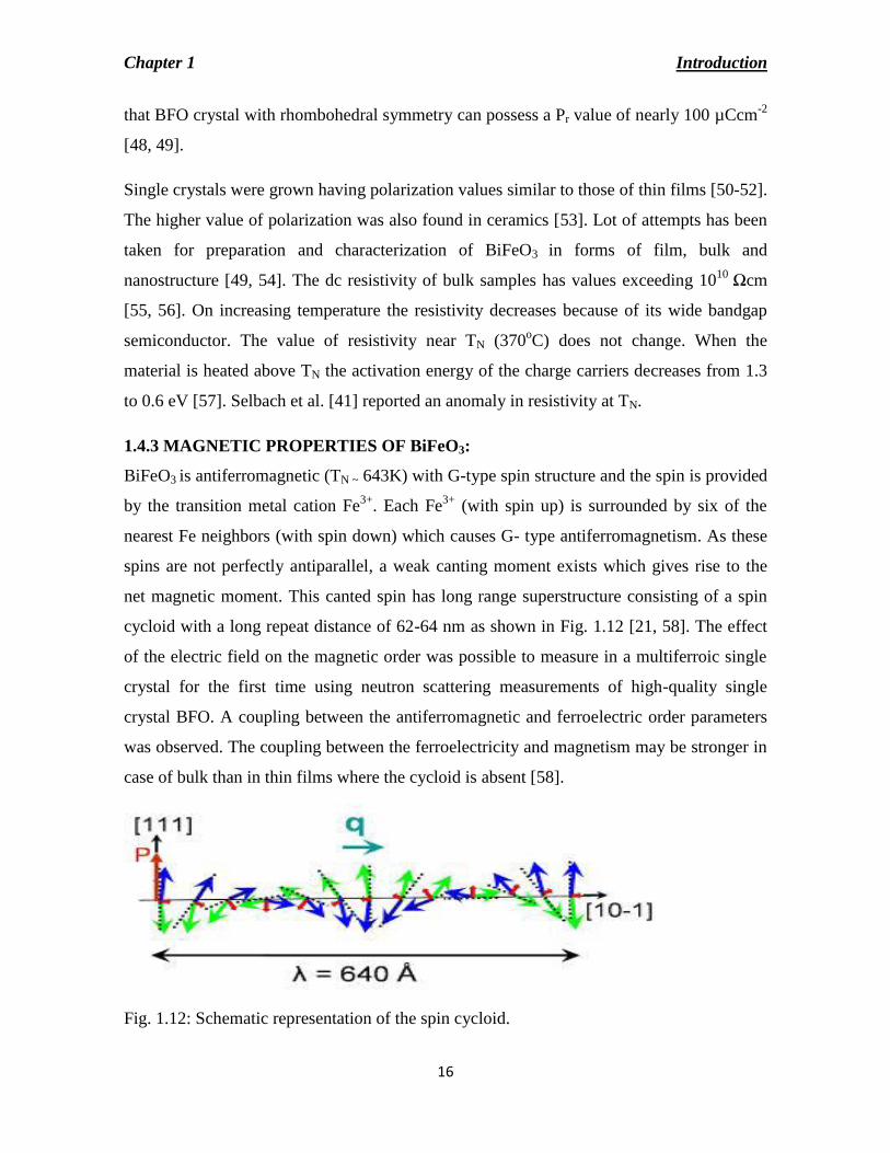
net magnetic moment. This canted spin has long range superstructure consisting of a spin
cycloid with a long repeat distance of 62-64 nm as shown in Fig. 1.12 [21, 58]. The effect
of the electric field on the magnetic order was possible to measure in a multiferroic single
crystal for the first time using neutron scattering measurements of high-quality single
crystal BFO. A coupling between the antiferromagnetic and ferroelectric order parameters
was observed. The coupling between the ferroelectricity and magnetism may be stronger in
case of bulk than in thin films where the cycloid is absent [58].
Fig. 1.12: Schematic representation of the spin cycloid.
Chapter 1 Introduction
17
When a high magnetic field (H > 18 Tesla) is applied there is a phase transition from the
spatially modulated AFM spin structure to a homogeneous one. In this case, the spiral is
destructed by high magnetic field [59, 60].
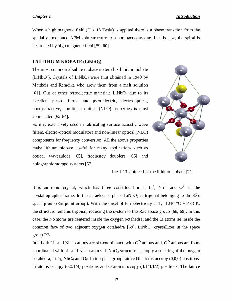
1.5 LITHIUM NIOBATE (LiNbO3)
The most common alkaline niobate material is lithium niobate
(LiNbO3). Crystals of LiNbO3 were first obtained in 1949 by
Matthais and Remeika who grew them from a melt solution
[61]. Out of other ferroelectric materials LiNbO3 due to its
excellent piezo-, ferro-, and pyro-electric, electro-optical,
photorefractive, non-linear optical (NLO) properties is most
appreciated [62-64].
So it is extensively used in fabricating surface acoustic wave
filters, electro-optical modulators and non-linear optical (NLO)
components for frequency conversion. All the above properties
make lithium niobate, useful for many applications such as
optical waveguides [65], frequency doublers [66] and
holographic storage systems [67].
Fig.1.13 Unit cell of the lithium niobate [71].
It is an ionic crystal, which has three constituent ions: Li+, Nb
5+ and O
2- in the
crystallographic frame. In the paraelectric phase LiNbO3 is trigonal belonging to the 𝑅3 𝑐
space group (3m point group). With the onset of ferroelectricity at Tc=1210 °C ~1483 K,
the structure remains trigonal, reducing the system to the R3c space group [68, 69]. In this
case, the Nb atoms are centered inside the oxygen octahedra, and the Li atoms lie inside the
common face of two adjacent oxygen octahedra [69]. LiNbO3 crystallizes in the space
group R3c.
In it both Li+ and Nb
5+ cations are six-coordinated with O
2- anions and, O
2- anions are four-
coordinated with Li+ and Nb
5+ cations. LiNbO3 structure is simply a stacking of the oxygen
octahedra, LiO6, NbO6 and O6. In its space group lattice Nb atoms occupy (0,0,0) positions,
Li atoms occupy (0,0,1/4) positions and O atoms occupy (4,1/3,1/2) positions. The lattice

Chapter 1 Introduction
18
parameters of LiNbO3 are a = 5.1483 Å and c = 13.8631 Å in hexagonal unit cell [70]. It
has 10 atoms in the unit cell in the ferroelectric phase. Each Nb atom is displaced from the
center of the oxygen octahedron along the polar axis. As in paraelectric phase the space
group is R3c the Nb atoms are centered inside the oxygen octahedra, and the Li atoms
inside the common face of two adjacent oxygen octahedra. The rhombohedral unit cell of
the ferroelectric structure contains two molecules of LiNbO3 (10 atoms) as shown in Fig.
1.13. It has been reported previously that Li-site is an active lattice site in the LiNbO3
crystallographic frame, which plays an important role in improving dielectric properties of
LiNbO3 crystals [72, 73]. It is a well-known non-linear optical crystal that exhibits an
extraordinary spontaneous polarization (71 µCcm–2
) [74].
1.6 SODIUM NIOBATE (NaNbO3)
Due to interesting electrical and mechanical properties Sodium niobate (NaNbO3) exhibits
important technological applications [75-79]. As compared to Pb (ZrxTi1-x)O3 (PZT)
alkaline niobates such as potassium-sodium niobate and lithium-sodium niobate exhibit
ultra large piezoresponse and hence gained considerable interest as the next generation eco-
friendly lead free piezoceramics [76, 77]. These lead free piezoceramics have wide
applications as transducers in cell phones, medical implants, etc. NaNbO3 finds application
in hologram recording materials and NaNbO3 nano-wires are useful for the lead free
piezoelectric nano-generator applications [80].
It is probably the most complex cubic perovskite known. At room temperature it is
antiferroelectric (Pbcm). At high-temperature it has a cubic structure. Below 913K six more
phases of structural phase transitions has been found. The successive phases are named as
T2, T1, S, R and P. All phases have orthorhombic symmetry except T2 which is tetragonal.
R phase is the most complicated one among the four orthorhombic phases present in the
temperature range 848–173 K. The unit cell of R phase contains 24 formula units. In all
these phases there is involvement of octahedral rotations or tilts. It is antiferroelectric
(orthorhombic symmetry) between 638 K-170 K and at low temperature (below 170 K) is
ferroelectric phase (rhombohedral).
Chapter 1 Introduction
19
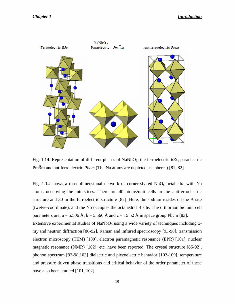
Fig. 1.14: Representation of different phases of NaNbO3; the ferroelectric R3c, paraelectric
Pm3 m and antiferroelectric Pbcm (The Na atoms are depicted as spheres) [81, 82].
Fig. 1.14 shows a three-dimensional network of corner-shared NbO6 octahedra with Na
atoms occupying the interstices. There are 40 atoms/unit cells in the antiferroelectric
structure and 30 in the ferroelectric structure [82]. Here, the sodium resides on the A site
(twelve-coordinate), and the Nb occupies the octahedral B site. The orthorhombic unit cell
parameters are; a = 5.506 Å, b = 5.566 Å and c = 15.52 Å in space group Pbcm [83].
Extensive experimental studies of NaNbO3 using a wide variety of techniques including x-
ray and neutron diffraction [86-92], Raman and infrared spectroscopy [93-98], transmission
electron microscopy (TEM) [100], electron paramagnetic resonance (EPR) [101], nuclear
magnetic resonance (NMR) [102], etc. have been reported. The crystal structure [86-92],
phonon spectrum [93-98,103] dielectric and piezoelectric behavior [103-109], temperature
and pressure driven phase transitions and critical behavior of the order parameter of these
have also been studied [101, 102].
Chapter 1 Introduction
20
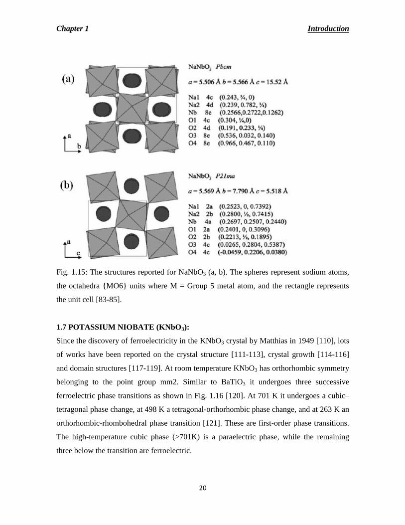
Fig. 1.15: The structures reported for NaNbO3 (a, b). The spheres represent sodium atoms,
the octahedra MO6 units where M = Group 5 metal atom, and the rectangle represents
the unit cell [83-85].
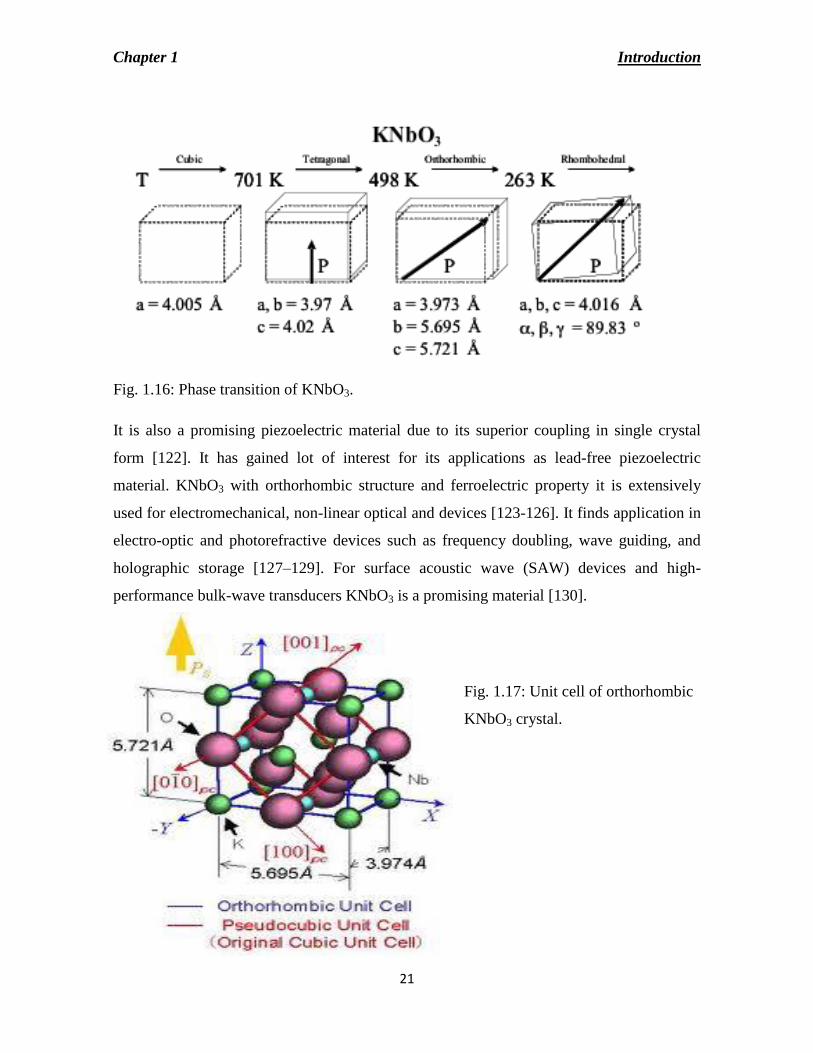
1.7 POTASSIUM NIOBATE (KNbO3):
Since the discovery of ferroelectricity in the KNbO3 crystal by Matthias in 1949 [110], lots
of works have been reported on the crystal structure [111-113], crystal growth [114-116]
and domain structures [117-119]. At room temperature KNbO3 has orthorhombic symmetry
belonging to the point group mm2. Similar to BaTiO3 it undergoes three successive
ferroelectric phase transitions as shown in Fig. 1.16 [120]. At 701 K it undergoes a cubic–
tetragonal phase change, at 498 K a tetragonal-orthorhombic phase change, and at 263 K an
orthorhombic-rhombohedral phase transition [121]. These are first-order phase transitions.
The high-temperature cubic phase (>701K) is a paraelectric phase, while the remaining
three below the transition are ferroelectric.
Chapter 1 Introduction
21
Fig. 1.16: Phase transition of KNbO3.
It is also a promising piezoelectric material due to its superior coupling in single crystal
form [122]. It has gained lot of interest for its applications as lead-free piezoelectric
material. KNbO3 with orthorhombic structure and ferroelectric property it is extensively
used for electromechanical, non-linear optical and devices [123-126]. It finds application in
electro-optic and photorefractive devices such as frequency doubling, wave guiding, and
holographic storage [127–129]. For surface acoustic wave (SAW) devices and high-
performance bulk-wave transducers KNbO3 is a promising material [130].
Fig. 1.17: Unit cell of orthorhombic
KNbO3 crystal.
Chapter 1 Introduction
22
As it has large electro-optic coefficient, high nonlinear optical coefficient, and excellent
photorefractive characteristics [131] it is used for optical devices such as optical
waveguides, frequency doublers [132], intensity modulators [133], optical switching and
modifiable interconnections [133], and holographic storage systems [134]. Fig. 1.17 shows
the unit cell of single crystal KNbO3. It has a pseudocubic perovskite structure unit cell
along and is slightly elongated along the Z-axis. The lattice constants of KNbO3 are; a =
0.5695 (nm), b = 0.3973 (nm), c = 0.5721 (nm) [136].
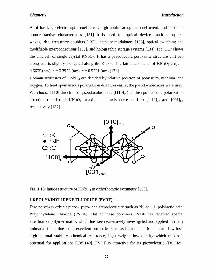
Domain structures of KNbO3 are decided by relative position of potassium, niobium, and
oxygen. To treat spontaneous polarization direction easily, the pseudocubic axes were used.
We choose [110]-direction of pseudocubic axes ([110]pc) as the spontaneous polarization
direction (c-axis) of KNbO3. a-axis and b-axis correspond to [1-10]pc and [001]pc,
respectively [137].
Fig. 1.18: lattice structure of KNbO3 in orthorhombic symmetry [135].
1.8 POLYVINYLIDENE FLUORIDE (PVDF):
Few polymers exhibit piezo-, pyro- and ferroelectricity such as Nylon 11, polylactic acid,
Polyvinylidene Fluoride (PVDF). Out of these polymers PVDF has received special
attention as polymer matrix which has been extensively investigated and applied in many
industrial fields due to its excellent properties such as high dielectric constant, low loss,
high thermal stability, chemical resistance, light weight, low density which makes it
potential for applications [138-140]. PVDF is attractive for its piezoelectric (Dr. Heiji

Chapter 1 Introduction
23
Kawai discovered in 1969), pyroelectrical and ferroelectric behavior [141-145]. PVDF and
its co-polymers find applications in electromechanical systems and charge storage
capacitors.
PVDF is a semi-crystalline polymer which is 50% amorphous. Lots of research work has
been reported on the piezoelectric, dielectric and pyroelectric properties of PVDF [141-
143]. The structure of monomer of this polymer is –CH2-CF2- and the chain occurs mainly
in head to tail configuration. The molecular weight of PVDF is in the range of 60-70
kg/mol [144]. It has a complex structure and depending upon the chain conformations as T
(trans) and G (gauche) linkages it has five distinct crystalline phases: non-polar α-phase and
ε -phase, as well as polar β-phase, γ-phase and δ- phase [145]. These crystalline phases can
be transformed into each other under specific conditions. Among all the phases, α and β are
the most common and melt processing commonly results in the non-polar α–phase. These
two phases have gained most interest because α-phase is thermodynamically stable at room
temperature and pressure and β –phase is kinetically stable under these conditions and
exhibits excellent piezoelectric, pyroelectric and ferroelectric properties [145]. The β –
phase of PVDF can be obtained from α–phase PVDF by mechanical stretching with a
temperature between 70-100oC and a stretch ratio of (Lfinal/Linitial) is in the range of 3-5
[146].
(a) α –phase (b) β – phase
Fig. 1.19: Structure of α – and β - phases of PVDF [147].

Chapter 1 Introduction
24
Fig. 1.19 shows the structure of α – and β - phases of PVDF. The α– phase of PVDF’s
occurs in trans-gauche- trans-gauche-(TGTG) formation. The structure is neither helical
(planar) nor zig-zag but a combination of two. The helical molecular shape is much lower
in energy than the planar zig-zag. The β- phase of PVDF forms a planar zig-zag or TT (T
means trans) bond that remains in the same plane as the carbon backbone which results in
most polar phase among others. PVDF crystals are mainly formed in β-phase due to the
transformation of α- to β- crystal induced by the stretching force.
1.9 CERAMICS -POLYMER COMPOSITES:
Multiferroics are considered as promising materials for sensors, storage media transducers
and spintronic devices as they provide a novel approach to the magnetic-electric field
conversion. Ceramics are brittle and difficult to manufacture whereas polymers are flexible
and easy to process at lower temperatures but they possess low permittivity. Because of the
fabrication of the desired shape/size and low cost (required for usages), they are highly
preferred. Thus, polymers are used to develop new materials as composites with ceramics
and/or metals matrix. Both polymer and ceramic create a composite material with new
results such as high dielectric constant, low dielectric, high breakdown strength etc. Now-a-
days polymer-ceramic composites are widely used for transducer applications, in high
pressure sensors, energy harvesting device, non-destructive testing applications, in under
water hydrophones, biomedical imaging with ultrasound and in embedded circuits [148-
150].
1.10 LITERATURE REVIEW:
Despite being a promising candidate for multifunctional applications, polycrystalline BFO
shows serious problems related to electrical conductivity, and a cycloidal disposition of the
magnetic moments forms a weak-ferromagnetic arrangement. It has been found that pure
BFO usually exhibits a high-leakage current arising out of its non-stoichiometry that limits
wide applications of this material [151-153]. It allows current to pass through when a high
voltage is applied. Due to high coercive field (EC) of BiFeO3 it is extremely difficult to pole
specimens into a ferroelectric state. To enhance the resistivity and lower EC lots of attempts
have been made such as doping various elements at A or B-site or forming solid solutions
with other perovskites.
Chapter 1 Introduction
25
In Nb-doped BiFeO3 ceramics unsaturated electric hysteresis loops were observed with
weak ferromagnetism (Mr = 0.015 emu/g) [154]. The substitution of lanthanum (La3+
) into
bulk BiFeO3 induces the destruction of the spin cycloid, and resulted in a magnetization
which is two times more than that of BiFeO3 [155]. Das et al. [156] demonstrated that the
presence of a small secondary phase in BiFeO3 was eliminated upon La substitution at the
Bi-site. In addition, they concluded that non-uniformity caused by La substitution enhanced
the multiferroic properties of BiFeO3. Structural analysis of Yb doped BiFeO3 resulted in
lattice distortion and maximum distortion observed was found when the concentration of
Yb was 15%. For this composition of Yb smallest leakage current density 10−7
A/cm2, and
the largest remnant polarization of 8.5 µC/cm2 was found [157]. By doping La
3+ and V
5+ at
the A and B sites of BiFeO3 respectively, very good electrical properties were observed.
The leakage current density of Bi0.85La0.15Fe0.97V0.03O3 ceramic was only 2.1×10⁻⁶
Acm−2
at
10 kVcm−1
, two and one orders of magnitude lower than that of the Bi0.85La0.15FeO3 and
BiFe0.97V0.03O3 [158]. Much improved magnetization at room temperature was observed
when Eu was substituted at the Bi-site. For Bi0.9Eu0.1FeO3 ceramics remnant polarization of
11 µCcm-2
and and magnetization of 0.0347 emu/g were found [159]. It was reported that
doping of Sr2+
ion in BiFeO3 showed improved magnetic hysteresis loops with some
remnant magnetization [160]. Addition of Sr stabilizes the BiFeO3 perovskite structure.
These ceramics exhibited enhanced dielectric permittivity and conductivity as compared to
undoped BFO due to increased concentration of oxygen vacancies. Doping of Sr in
BiFeO3 gives rise to increased grain boundary conductivity [161]. Gu et al. [162] reported
that reduced leakage current, and huge electrical resistivity of over 104 Ω cm was found on
doping Ti in BiFeO3. The Fe-deficiency in BiFe0.9Ti0.05O3 decreased the amount of Fe²⁺
which led to ultrahigh electrical resistivity. At room temperature this ceramic displayed a
low dielectric loss, 0.015 at 100 Hz, a remnant polarization of 0.23 μC/cm² and a remnant
magnetization of 0.13 emu/g. Y doping in BFO increases magnetization and reduces band
gap making it potential for magnetoelectric and photocatalytic applications [163]. Study of
electrical properties of Y doped BFO were carried out and found that the value of activation
energy increases with increase of yttrium content, and hence resistivity of the samples
increases. This implies that the leakage current decreases with increase of yttrium doping. It
was also seen that the dielectric permittivity increases with increase in yttrium

Chapter 1 Introduction
26
concentration. It was found that the dielectric permittivity of the samples depends both on
grain resistance and interfacial grain boundary resistance [164]. Ferromagnetism was
observed in pure and Gd-doped BiFeO3 nanoparticles. With increase in doping
concentration the magnetization value increases. For the doped samples well-saturated
ferroelectric hysteresis loops were observed. As a result of doping the leakage current
density decreases by four orders [165]. The magnetic properties of BFO were improved by
introducing Dy at the Bi-site of BFO. Well saturated ferroelectric hysteresis loops and
polarization switching currents were observed at room temperature. A large remnant
polarization (2Pr) value of 62 µC/cm2 was achieved which is the highest value reported so
far for rare-earth-doped BFO ceramics [166]. Pr doping in BFO reduces the grain size and
found that there was reduction in leakage current with increase in Pr content [167]. Zhou et
al. [168] reported that in Er-doped BiFeO3 the remnant magnetization increases with
increase in Er content. This increase is attributed to the co-contribution of both
ferromagnetic coupling between Er3+
and Fe3+
ions and the suppression of spatial spin
structure of BiFeO3. Low dielectric loss of the doped samples indicated reduction in
leakage current. Ni-incorporated BiFeO3 significantly enhanced the magnetization when Ni
concentration reaches to x= 0.1 at 5 K. Temperature dependence of dielectric constant in
BiFe0.95Ni0.05O3, BiFe0.9Ni0.1O3 and BiFe0.85Ni0.15O3 samples exhibits dielectric anomalies
approximately around 450oC, 425
oC and 410
oC respectively. These anomalies can be
related to antiferromagnetic to paramagnetic phase transition of the parent compound
BiFeO3 [169]. In Sm doped BiFeO3 with increase of Sm-content the grain size decreases.
Enhanced spontaneous magnetization was attributed to structural distortion and partial
destruction of spiral spin structure. With increase in Sm content enhanced magneto-electric
coupling coefficient of BFO could be achieved [170].
A complete structural transformation from rhombohedral to tetragonal symmetry is
observed in solid solution of BFO and LiNbO3 taken in equal molar ratio
[(Bi0.5Li0.5)(Fe0.5Nb0.5)O3]. It is seen that the ME coupling coefficient has greatly been
improved on addition of LiNbO3 to BFO [171]. Choudhary et al. [172] reported that the
solid solution of Pb(Fe2/3W1/3)O3 - BiFeO3 showed the formation for tetragonal crystal
system and frequency and temperature dependence of dielectric parameters. They found
that on substituting 10% of BiFeO3 in Pb(Fe2/3W1/3)O3 dielectric parameters of solid

Chapter 1 Introduction
27
solution show unique relaxor characteristics. The sharp tan δ peaks diffuse on increasing
BiFeO3 content. On making composites of Pb(Zr,Ti)O3 (PZT) in the BiFeO3 matrix higher
tan δ value (is a major problem in BiFeO3) has been drastically reduced. Addition of PZT to
BFO increases the dielectric constant initially but then decreases on further increase of PZT
content (i.e., x > 0.25) [173]. On increasing NaNbO3 content in BFO ceramics the
crystalline structure can be changed, with improvement of its ferroelectric properties. Due
to reduction in leakage current a more regular hysteresis loops was observed. In
(Bi0.9Na0.1)(Fe0.9Nb0.1)O3 ceramics two dielectric anomalies were found around 550–600 K
and 650–710 K. In this ceramic a weak ferromagnetism with Mr of 0.14 emu/g and Hc of
6.48 kOe was observed [174]. Solid solution of BiFeO3 and DyFeO3 significantly enhanced
the dielectric and magnetic properties. As a result of destruction of the spiral spin
modulation a weak ferromagnetism with large saturated magnetization at low temperatures
was observed [175]. Solid solution of BiFeO3 and BaTiO3 nanostructures exhibited non-
zero magnetization with remnant magnetization values of Mr ≥ 0.32 emu/g. The hysteresis
loops for all the compounds exhibited smaller coercivity values at 10 K as compared to
those at 300 K [176]. Chandarak et al. [177] reported that the solid solution of 0.8BiFeO3-
0.2BaTiO3 showed highest dielectric constant (εr =19000). This giant-dielectric behavior
was attributed to the multivalent states of Fe, as well as to the better grain packing density
with increase in BaTiO3 content. Solid solution of Dy substituted BiFeO3and
Pb(Fe2/3W1/3)O3 showed antiferromagnetic behavior of the material with weak
ferromagnetism (remanent magnetization 121.9 emu/mol and coercive field as 890 Oe). A
strong dependence of the ME coefficient on frequency was also found [178]. Mixed spinel–
perovskite composites of xMnFe2O4–(1–x)BiFeO3 with x=0, 0.1, 0.2, 0.3 and 0.4 resulted
in increase in magnetization with increasing concentration of ferrite content [179]. Dash
et.al [180] reported that dielectric loss and leakage current of BFO is greatly reduced with
increase in concentration of NaNbO3. The value of ME coefficients in these compounds
suggests that they will be useful for multiferroics devices. The composites of 0.7BiFeO3-
0.3BaTiO3 and Y3Fe5O12 (BFO-BTO-YIG) showed that the BFO-BTO and YIG phases
coexist. They found enhanced ferromagnetic property with Ms value of 1.4 emu/gm, and a
typical square polarization hysteresis loop with a Pr value of 19.3µC/cm2, which is equal to
that of BFO-BTO [181]. A structural phase transformation from rhombohedral to tetragonal

Chapter 1 Introduction
28
symmetry was observed when concentration of Na0.5K0.5NbO3 is 15% in a solid solution of
BiFeO3 and Na0.5K0.5NbO3. For this sample ferromagnetism was observed at room
temperature but with increase in Na0.5K0.5NbO3 content ferromagnetism disappears.
Improved ferroelectric property with remnant polarization and coercive electric field of
1.83 μC/cm2 and 11.2 kV/cm for the sample of x = 0.18 respectively were found [182]. At
room temperature an orthorhombic structure was obtained in a composite of Gd doped
BiFeO3 and PbZrO3. A major contribution of bulk effect and a slight indication of grain
boundary effect from Nyquist plot were seen [183]. Qi et al. [184] reported that multiferroic
composites of BiFeO3 and NiCuZn showed ferroelectric phase and ferromagnetic phase can
co-exist and exhibits typical magnetic hysteresis loops. They found that on increasing
NiCuZn content the saturation magnetization of composites linearly decreases. They also
showed that the real part of permeability decreases with increasing NiCuZn content and the
peak of imaginary part of permeability shifts toward higher frequency. Incorporation of
KNbO3 to BiFeO3 enhances the dielectric, ferroelectric and ferromagnetic properties of
BiFeO3. On increasing KNbO3 content the leakage current or tangent loss of BiFeO3 is
greatly reduced. Contributions of grain and grain boundaries in the resistive and transport
properties of the materials were observed [185].
For better performances and wide applications of PVDF, its dielectric permittivity,
conductivity, ferroelectricity should be tailored or enhanced. As a composite is multi-phase
system, it can serve the purpose because its individual component cannot. Now it is a well-
established fact that physical (permittivity, conductivity, resistive, etc), chemical and
mechanical properties of PVDF can be modified by introducing some functional fillers of
metal/ceramics of different particle/grain size. In order to achieve enhanced (high)
dielectric properties (permittivity, piezo- and pyro-electric, polarization), some attempts
have been taken in preparing composites by introducing some ferroelectric ceramics.
Composite of LaCCTO with PVDF resulted in increased dielectric constant and Young’s
modulus [186]. Fibrous BaTiO3/PVDF composite showed high flexibility which can have
application in vibration energy harvesters [187]. PVDF/PZT nanocomposite films exhibited
enhanced dielectric constant but no change in dielectric loss in a frequency range of 100
Hz-30 MHz [188]. 50% BST60/40/PVDF ceramic-polymer composite resulted in increased
thermal strength of the composite [189]. BFO-PVDF nanocomposite films prepared by hot-
Chapter 1 Introduction
29
pressed method showed enhanced dielectric, conductivity and magnetocapacitance as
compared to pure BFO [190]. BFO and poly (vinylidene fluoride –trifluor-oethylene) [P
(VDF+TrFE)] composite nanofibers fabricated by electrospinning method revealed the
coexistence of electric and magnetic hysteresis at room temperature [191]. PbTiO3-PVDF
composite revealed that the pyroelectric sensitivity increases with increase in PbTiO3
content and the piezoelectric coefficient decreases slightly with hydrostatic pressure [192].
PVDF/CCTO nanocrystal composite thick film resulted in high dielectric permittivity of
290 at 125oC at 100 Hz and dielectric constant increases with CCTO content but there was
a decrease in dielectric breakdown which limits its application at higher voltages [193].
Stontium Barium Niobate (Sr0.7Ba0.3Nb2O6) ceramic nanopowder - PVDF composite
showed improved dielectric properties and the pyroelectric coefficient increases from 24
µC/cm2K in pure polymer to 40 µC/cm
2K in composites [194].
1.11 COMPOUNDS UNDER PRESENT INVESTIGATION:
In the present study, the effect of substitution of alkali niobate on some physical properties
of BiFeO3 has mainly been studied. The studied samples have been grouped as follows.
(i) Group A: ceramics
(1-x) BiFeO3 + (x) ANbO3
Where A = Li, Na, K and x=0, 0.1, 0.2, 0.3, 0.4 and 0.5
(ii) Group B: Ceramic-polymer composites
y [(1-x) BiFeO3 + (x) ANbO3] + (1-y) PVDF
Where A = Li, Na, K and x=0, 0.5 (with volume fraction y = 0 and 0.5)].
(a) 0.5 BiFeO3 + PVDF (BFOP)
(b) 0.5 BiFeO3 + 0.5 LiNbO3 + PVDF (BLFNP)
(c) 0.5 BiFeO3 + 0.5 NaNbO3 + PVDF (BNFNP)
(d) 0.5 BiFeO3 + 0.5 KNbO3 + PVDF (BKFNP)
1.12 OBJECTIVES AND SCOPE OF RESEARCH:
The objectives of the present work have been defined on the basis of the existing problems,
challenges and current status in the field of multiferroics. A brief outline is given as
follows:
Preparation of materials using a high temperature solid-state reaction technique.

Chapter 1 Introduction
30
Study of the preliminary structural and microstructural properties of the compounds.
Study of the dielectric properties in a wide range of temperature and frequency.
Study the electric polarization of the compounds.
Analysis of the electrical properties of the compounds by complex impedance
spectroscopy technique.
Study the I~V characteristics of compounds.
Study the magnetization in the compounds as a function of magnetic field.
1.13 ORGANIZATION OF THE THESIS:
The thesis is divided into seven chapters, the contents of which are as follows:
Chapter 1 gives a brief introduction to the broad area of ferroelectric and
multiferroics and its related materials. A brief account on multiferroic phenomenon
has been presented which covers an overview of the conceptual, theoretical and
material aspects. In addition to this literature survey, describe the chronological
development and current status of the compounds has been discussed.
In chapter 2 the sample preparation technique is elucidated in details. Some
common analysis methods are surveyed and a brief description of the instruments
and setups used in the present investigation is given.
Chapter 3 reports the experiment results and their interpretation on structural and
micro structural- characteristics of the compounds.
Chapter 4 is devoted to the understanding of the dielectric and ferroelectric
properties of the compounds.
Chapter 5 deals with an extensive study of complex impedance spectroscopy of the
compounds.
Chapter 6 discusses about the ac and dc conductivity and I~V characteristics of the
compounds.
Chapter 7 deals with the magnetic properties of the compounds.
Chapter 8 gives a brief summary, conclusion and future scope of the work.