Chapter 1 Introduction - homepage.cs.uri.edu · 1.3 Objectives In this study, ... Chapter 6...
87
1 Chapter 1 Introduction 1.1 Statement of Problem Joint Operations Virtual Environment (JOVE) is a software application that provides a virtual environment for collaborative applications such as crisis action planning [1]. It has been developed by the Office of Naval Research through the Naval Command, Control and Ocean Surveillance Center (NRaD) with contractor support from Science Applications International Corporation (SAIC). JOVE integrates Multi-User Virtual Environment (MUVE) technology, available World Wide Web (WWW) resources, and Commercial-off-the-shelf products to create a distributed collaborative virtual environment for applications, such as humanitarian assistance operations. A MUVE is an inherently collaborative computer environment that provides facilities for navigation around virtual locations, as well as for information sharing and communication among widely distributed users. The JOVE environment provides buildings and rooms within the buildings in which users can maintain their own information (a private office), and meet with other users in virtual conference rooms. In these virtual meetings, users can remotely brief each other, discuss critical issues (publicly and privately), search databases for pertinent information, provide immediate
Transcript of Chapter 1 Introduction - homepage.cs.uri.edu · 1.3 Objectives In this study, ... Chapter 6...

1
Chapter 1
Introduction
1.1 Statement of Problem
Joint Operations Virtual Environment (JOVE) is a software application that
provides a virtual environment for collaborative applications such as crisis action
planning [1]. It has been developed by the Office of Naval Research through the Naval
Command, Control and Ocean Surveillance Center (NRaD) with contractor support from
Science Applications International Corporation (SAIC). JOVE integrates Multi-User
Virtual Environment (MUVE) technology, available World Wide Web (WWW)
resources, and Commercial-off-the-shelf products to create a distributed collaborative
virtual environment for applications, such as humanitarian assistance operations.
A MUVE is an inherently collaborative computer environment that provides
facilities for navigation around virtual locations, as well as for information sharing and
communication among widely distributed users. The JOVE environment provides
buildings and rooms within the buildings in which users can maintain their own
information (a private office), and meet with other users in virtual conference rooms. In
these virtual meetings, users can remotely brief each other, discuss critical issues
(publicly and privately), search databases for pertinent information, provide immediate

2
updates to each other, electronically gather and poll for critical assessment information,
and store information for critical action team use.
The JOVE system has been designed using the Rational Rose Design Tool [2].
Rational Rose is an implementation of the Unified Modeling Language (UML) standard
developed by the Object Management Group (OMG) [3]. The Unified Modeling
Language (UML) is the industry-standard expressive visual modeling language for
specifying, visualizing, constructing, and documenting the artifacts of software systems,
especially targeting the modeling of concurrent, distributed systems. It simplifies the
complex process of software design, making a "blueprint" for construction. UML fuses
the concepts of Booch, OMT, and OOSE [4]. UML incorporates the object-oriented
communities consensus on core modeling concepts, independent of particular
programming languages and development processes.
1.2 MOTIVATION
The collaborative nature of the JOVE system allows multiple users across the
world to work together in determining the most effective plan of action. In some crisis
actions, the JOVE may need to be employed by multiple parties to acquire timely
information and make fast and accurate decisions and plans in order to address critical
humanitarian needs. In such an environment, providing support for representation of real-
time data can further enhance the ability to make critical decisions. For instance, in a
3
crisis meeting about an impending hurricane, the planning involved in minimizing
casualties and property damage would require collaboration among various groups,
including the National Weather Service, local police and fire departments, the National
Guard, local television and radio stations, etc. In such a distributed collaborative virtual
environment, users may share information such as planned evacuation routes, population
reports and satellite data. Some of this information, the satellite data for instance, should
be updated periodically, otherwise users may make a bad decision based on out-of-date
information. Therefore real-time representations of such data are required in order to
provide the best information to the users. In such a critical application, real-time
concurrency control will also be required among the various requests being made by the
users. Incorporating real-time objects with real-time concurrency control into the JOVE
architecture is important and necessary.
There are unique challenges faced in real-time software development. For real-
time system developers, understanding the impact of design decisions and effectively
communicating functionality can be a daunting task. An overriding concern is the
architecture of the software. This refers to the essential structural and behavioral
framework on which all other aspects of the system depend. Since UML is proven as a
good architectural design pattern and has a strong set of general purpose modeling
language concepts applicable across domains, it is extremely useful to capture the UML
as first-class modeling constructs to facilitate the design of good architectures of real-
time system software. Thus investigating adding real-time features into UML/Rational

4
Rose Design Tool, for example, how to express the timing constraints, is one of the
necessary and challenging issues in this project.
The Real-time research group at the University of Rhode Island (URI) has
designed the RTSORAC (Real-Time Semantic Objects, Relationships and Constraints)
model for real-time object-oriented database systems [5]. The RTSORAC model
incorporates features that support the requirements of a real-time database into an
extended object-oriented model. It supports data temporal consistency requirements and
time-constrained transactions by specifying objects that contain: attributes with value,
time and imprecision fields; constraints on each of those fields; and semantically defined
compatibility of object methods. It also provides the semantic locking mechanism for
concurrency control. Applying this RTSORAC model into the real-time JOVE system
would be another challenging part of this project. In this paper, we focus on real-time
objects in JOVE.
1.3 Objectives
In this study, our primary research objective is to develop a model to integrate
real-time objects into the existing JOVE software to meet distributed and real-time
requirements. To this end, we have integrated the RTSORAC model objects into the real-
time JOVE system using the Rational Rose Design Tool. We have also implemented the
Semantic Locking Mechanism for concurrency control. Finally, we have installed the

5
real-time items into the existing JOVE system and tested to ensure that the design and
implementation of the real-time items is correct.
1.4 Thesis Outline
Chapter 2 provides background and related work that has formed the foundation
for the work of this thesis. It introduces the JOVE system and contains a review of the
MySQL database, JDBC(Java Database Connectivity) connection and Java IDL(Interface
Definition Language). It also provides the background on the real-time system, UML for
real-time, real-time CORBA and the RTSORAC model. Chapter 3 presents the design of
real-time items. Chapter 4 describes the implementation and integration details of real-
time items in the JOVE system with CORBA and the MySQL database. Chapter 5
demonstrates the correctness and performance evaluations of the RT JOVE system.
Chapter 6 concludes the thesis with a summary and discussion of its contributions and
limitations, and future work.

6
Chapter 2
Background and Related Work
In this chapter, we will describe the background and previous work related to the
design and implementation of the integration of real-time items in the JOVE system.
First, we will introduce the JOVE system, including its architecture, information items,
MySQL database, JDBC connection and CORBA. Next we will describe real-time
systems. We will also describe the Unified Modeling Language (UML), its
implementation in the Rational Rose Design Tool and some proposed UML constructs
for real-time design. Finally, we will describe real-time CORBA and the RTSORAC
model developed by the URI real-time research group.
2.1 JOVE
The JOVE system is a computer-mediated environment in which users perform
collaborative tasks, i.e. decision making, from distributed locations. The objective of the
JOVE project is to capitalize on advanced information technology in order to provide a
better environment for crisis action planning.
7
2.1.1 JOVE System Architecture
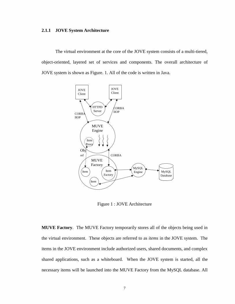
The virtual environment at the core of the JOVE system consists of a multi-tiered,
object-oriented, layered set of services and components. The overall architecture of
JOVE system is shown as Figure. 1. All of the code is written in Java.
JOVEClient
JOVEClient
HTTPDServer
CORBAIIOP
CORBAIIOP
MUVEEngine
ItemProxy
Item
Item
ItemFactory
MUVEFactory
MySQLEngine MySQL
Database
ref
ObjCORBA
Figure 1 : JOVE Architecture
MUVE Factory. The MUVE Factory temporarily stores all of the objects being used in
the virtual environment. These objects are referred to as items in the JOVE system. The
items in the JOVE environment include authorized users, shared documents, and complex
shared applications, such as a whiteboard. When the JOVE system is started, all the
necessary items will be launched into the MUVE Factory from the MySQL database. All

8
these items are stored in the MUVE Factory until the items are requested to be deleted
explicitly by users or the JOVE system is shut down or it crashes. When a request for an
item is made to the MUVE factory from the MUVE Engine, the system checks the Item
Factory object to determine if the requested item exists in the MUVE factory. If it does,
the reference to the requested item is returned. If the item does not exist in the MUVE
factory, the Item Factory creates an item in the MUVE factory by querying the MySQL
database (see Section 2.1.3) for information on the requested item. The Item Factory
then returns the reference to the newly created Item.
The MUVE Factory is responsible for persisting the items that it contains. A
thread in the MUVE Factory periodically and atomically writes the data in all of the
items to the MySQL database via a JDBC connection(see Section 2.1.4).
MySQL Database. The MySQL database (See Section 2.1.3) is relational and it provides
a way to store objects in the JOVE system persistently [6]. Whenever an item requested
by the user or the system is not stored in the MUVE Factory, the MUVE Factory will
query the MySQL database and create a new item. The MySQL database also inserts or
updates items on the request of the MUVE Factory.
MUVE Engine. The MUVE Engine acts as a server to the distributed clients. It is
multi-threaded and it contains references to items in the MUVE Factory that have been
requested by users. The connection between the MUVE Engine and the MUVE Factory,

9
as well as the connection between the MUVE Engine and the distributed clients are made
using the CORBA distributed object computing standard (to be discussed in Section
2.1.5). The MUVE Engine handles multiple requests concurrently in a first-come-first-
served fashion.
Clients. A JOVE client is a stand-alone Java application. It presents a graphical
interface to the user in which the user can view the current room she is in, certain items
and applications in the room, other users in the room, and pathways to other rooms and
buildings in the environment. The client is connected to the MUVE Engine through
CORBA IIOP (Internet Inter-ORB Protocol) [7] (see Section 2.1.5). The client also
connects to an HTTP server that provides access to certain graphical data, as well as
access to URLs in the environment.
In a typical client server interaction, the client makes a request for a particular
item in the environment. The request goes to the MUVE Engine through CORBA IIOP.
In the MUVE Engine, the request is handled by a thread that is scheduled in FIFO order.
The MUVE Engine accesses the Item Factory in the MUVE Factory to determine if the
requested item is already in the MUVE Factory. If it is, then the object reference for the
item is passed to the thread in the MUVE Engine which in turn returns an object
reference to the client. If the item does not already exist in the MUVE Factory, the Item
Factory object queries the MySQL database for the requested item. The item returned by
MySQL is stored in the MUVE Factory and an object reference is returned to the MUVE

10
Engine and eventually to the client. Once the client has a reference to a particular item, it
can call methods on the item object as if it were in its own address space.
2.1.2 MySQL database
MySQL is a multi-user, multi-threaded relational SQL (Structured Query
Language) database server [6]. It is a client/server implementation that consists of a
server daemon mysqld and several client programs and libraries. The main goals of
MySQL are speed, robustness and ease of use. MySQL has JDBC drivers, which allows
interfacing with a Java client. It has an Open DataBase Connectivity (ODBC) interface
for Windows 95/NT.
The JOVE architecture uses MySQL for persistence of item objects. Because
MySQL is a relational database, and the JOVE items are Java objects (or class instances),
when an object is persisted in the MySQL database, the object’s class is represented by a
table, the object’s attributes are represented as table columns and object instances are
represented as table rows.

11
2.13 JDBC
The JDBC API of Java is a standard SQL database access interface, developed by
Sun and its Java partners [8]. This API provides Java programmers with a uniform
interface to a wide range of relational databases, and provides a common base on which
higher level tools and interfaces can be built. The JDBC API defines Java classes to
represent database connections, SQL statements, result sets, database metadata, etc. It
allows a Java programmer to issue SQL statements and process the results. Thus, JDBC
is the primary API for database access in Java.
With help from JDBC, Java’s ability to integrate with popular commercial DBMS
and its network-oriented nature make it an ideal client/server computing environment.
Therefore, the JOVE system uses JDBC as the connection between the MUVE Factory
and the MySQL database. The JDBC API is implemented via a driver manager that can
support multiple drivers connecting to different databases. In this project, the JDBC API
is implemented via the JDBC driver for MySQL database.
2.1.4 CORBA/IIOP/Java IDL
CORBA. Distributed object computing has become a widely accepted programming
paradigm for applications that require seamless interoperability among heterogeneous
clients and servers. CORBA (Common Object Request Broker Architecture) is a standard

12
for distributed objects being developed by the Object Management Group (OMG) [7].
CORBA specifies the Object Request Broker (ORB) that allows applications to
communicate with one another no matter where they reside on a network. The CORBA
ORB is an application framework that provides interoperability between objects, built in
(possibly) different languages, running on (possibly) different machines in heterogeneous
distributed environments. CORBA also specifies an Interface Definition Language (IDL)
for description of interfaces to the functional behavior of distributed components.
IIOP. The General Inter-ORB Protocol (GIOP) is the OMG protocol for ORB
interoperability. It allows different ORB implementations to communicate without
restricting ORB implementation flexibility, which means a client of an ORB can invoke
operations on an object in a different ORB via GIOP. The Internet Inter-ORB Protocol
(IIOP) is the mapping of GIOP message transfers to TCP/IP connections. IIOP is an
underlying mechanism of CORBA technology, which is transparently managed by ORBs.
So IIOP and CORBA are, essentially, inseparable. Therefore, programmers and users are
never required to interact with IIOP in any way; it is invisible to them.
One of the most important aspects of CORBA/IIOP is its platform independence.
CORBA ORBs interoperate without regard to vendor origin. This platform independence
allows businesses to take advantage of the Internet without having to rebuild systems and
networking hardware and software of forcing them to commit to a single vendor solution.
CORBA/IIOP will allow most every system that is now in operation to be incorporated
with comparatively minor modifications so that a business’s installed base, even if it is
13
made up of equipment and software packages from a variety of vendors, will be able to
work together seamlessly.
CORBA IDL. A key feature of CORBA is IDL, a language-neutral Interface Definition
Language. The Interface Definition Language (IDL) is the language used to describe the
interfaces that client objects call and object implementations provide. An interface
definition written in IDL completely defines the interface and fully specifies each
operation’s parameters. An IDL interface provides the information needed to develop
clients that use the interface’s operations. Clients are not written in IDL, which is purely
a descriptive language, but in languages for which mappings from IDL concepts have
been defined. The mapping of an IDL concept to a client language construct will depend
on the facilities available in the client language.
Java IDL. Each language that supports CORBA has its own IDL mapping. Java IDL
is SUN’s implementation of mapping from Java to IDL [9]. Thus, Java IDL is a
technology for distributed objects--that is, objects interacting on different platforms
across a network. Java IDL not only supports distributed objects written entirely in the
Java programming language, but also enables objects to interact regardless of whether
they are written in the Java programming language or another language such as C, C++,
COBOL, or others. To support interaction between objects in separate programs, Java
IDL provides an Object Request Broker, or ORB. The ORB is a class library that enables
low-level communication between Java IDL applications and other CORBA-compliant
applications.

14
The JOVE system is coded entirely in Java, and its CORBA implementation is
Java IDL. Thus, the JOVE system provides a CORBA/IIOP interface (Java ORB) for
connection between the MUVE Engine and the MUVE Factory, and connection between
the Client and the MUVE Engine.
2.2 Real Time Systems
Many real-world computing systems are associated with time constraints [10].
These time constraints require that the computations must complete before their
deadlines, otherwise various degrees of damage may occur. Such systems are called real-
time (RT) systems. This requirement typically comes from the system interacting with
the physical environment such as the military command and control, nuclear power
plants, automatic manufacturing factories, crisis action management, and air traffic
control systems. The environment produces stimuli, which must be accepted by the real-
time system within timing constraints. The environment further requires control output,
which must be produced within timing constraints. For example, some timely information
must be retrieved to make crisis action decisions in an impending hurricane meeting.
A critical aspect of real-time systems is how time itself is handled. The design of
a real-time system must identify the timing requirements of the system and ensure that
the system performance is both correct and timely. Hard real-time systems require
deadlines absolutely must be met. A missed deadline would cause a fatal system failure.

15
In these systems, late data causes system failure. Soft real-time systems are constrained
only by average time constraints. If a single computation is late, it is not usually
significant, although consistently late computation can result in system failures. In these
systems, late data is still good but not as good as on time data. Firm real-time systems’
requirement is between that of hard and soft real-time systems and late data is useless. In
this project, the RT JOVE is a soft real-time system.
2.3 UML for Real-Time
The Unified Modeling Language, or UML, is a third-generation object-oriented
modeling language. Because the UML is meant to be applicable to the modeling of all
types of systems, it applies equally well to real-time systems, client/server, and other
kinds of “standard” software applications. It provides a rich set of notations and promises
to be supported by all major CASE tool vendors.
2.3.1 Modeling with UML Diagrams
The UML distinguishes between the notions of model and diagram [14]. A model
contains all of the underlying elements of information about a system under consideration
and does so independently of how those elements are visually presented. A diagram is a
particular visualization of certain kinds of elements from a model and generally exposes

16
only a subset of those elements’ detailed information. In this section, we will describe
class diagram, sequence diagram, collaboration diagram and state diagram.
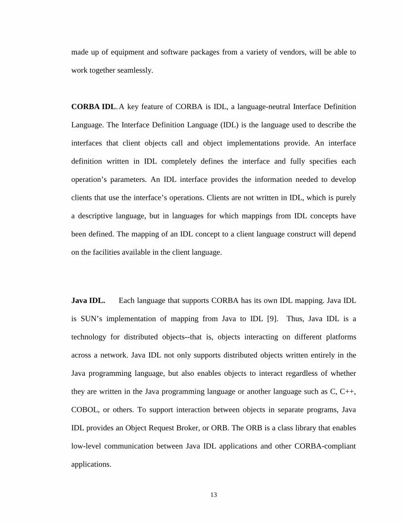
A class diagram shows the important abstractions in a system and how they relate
to each other. The primary elements found on class diagrams are class icons and
relationship icons. Figure 2 shows an example of class diagram for satellite image
processing in the hurricane emergency planning project room. There are 5 classes – Item,
ItemServer, ImageServer, SatelliteImage, BlackBox and HurricaneRoom (see Figure 2),
with attributes and operations. The ItemServer class has an attribute ItemCount and three
operations: CreateItem(), DeleteItem() and GetItem(). In addition to classes with
attributes and operations, class diagrams also depict relationships that exist between
dependent classes, including association, aggregation, inheritance, dependency and
instantiates. In this example, class HurricaneRoom has an association with class
SatelliteImage. An association is used to represent a structural dependency between
objects, generally of different classes. Class ImageServer extends class ItemServer, and
SatelliteImage extends Item. These are the inheritance relationships. An ItemServer may
be composed of Items, and an ImageServer may be composed of image items, including
the SatelliteIamge. Thus, they are the aggregation relationships, which is used to show
that one kind of object is composed, at least in part, of another.
17
Figure 2 : Class Diagram of Hurricane Example
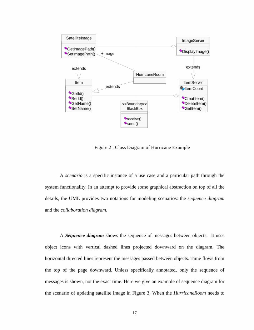
A scenario is a specific instance of a use case and a particular path through the
system functionality. In an attempt to provide some graphical abstraction on top of all the
details, the UML provides two notations for modeling scenarios: the sequence diagram
and the collaboration diagram.
A Sequence diagram shows the sequence of messages between objects. It uses
object icons with vertical dashed lines projected downward on the diagram. The
horizontal directed lines represent the messages passed between objects. Time flows from
the top of the page downward. Unless specifically annotated, only the sequence of
messages is shown, not the exact time. Here we give an example of sequence diagram for
the scenario of updating satellite image in Figure 3. When the HurricaneRoom needs to
ImageServer
DisplayImage()
ItemServer
ItemCount
CreatItem()DeleteItem()GetItem()
extends
Item
GetId()SetId()GetName()SetName()
SatelliteImage
GetImagePath()SetImagePath()
extends
HurricaneRoom
extends
+image
BlackBox
receive()send()
<<Boundary>>

18
update the satellite image, it gets the SatelliteImage object reference from the
ImageServer. If the SatelliteImage object does not exist, the ImageServer will create the
SatelliteImage object first. After it gets the SatelliteImage object reference, it updates
satellite image by calling the updating methods of the SatelliteImage object.
Figure 3 : A Hurricane Example of Sequence Diagram
Collaboration diagrams show objects, their links, and their messages. They can
also contain simple class instances and class utility instances. Each collaboration diagram
provides a view of the interactions or structural relationships that occur between objects
and object-like entities in the current model. In a collaboration diagram, sequence
numbers must be attached to the messages to indicate the relative order in which the
The SatelliteImageconstructor is calledonly if object does notexist in the ImageServer yet.
: HurricaneRoom
:BlackBox :ImageServer :SatelliteImage
1: receive(updatesatellite image)
2: GetItem()
4: Item
5: SetName()
6: SetImagePath()
3: SatelliteImage()
7: send(update)

19
messages are sent in the scenario. The arrows show the message direction. We can see
that sequence progression is more prominent in the sequence diagram, but structure is
more obvious in the collaboration diagram. The above scenario of updating satellite
image can be modeled by using a collaboration diagram as shown below in Figure 4.
After the BlackBox receives the updating satellite image command from the
HurricaneRoom, it gets the SatelliteImage object reference from the ImageServer. Then it
updates satellite image by calling the updating methods of the SatelliteImage object.
Figure 4 : the Hurricane Example of Collaboration Diagram
A state diagram is used to show the state space of a given class, the events that
cause a transition from one state to another and the actions that result from a state change.
Each state diagram is associated with one class or with a higher-level state diagram. A
state diagram is a directed graph of states connected by transitions. A state diagram
describes the life history of objects of a given class. A state diagram shows exactly one
: Hurricane Room
:BlackBox
:ImageServer
:SatelliteImage
1: receive(update satellite image)
2: GetItem()
3: SatelliteImage()
4: Item
5: SetName()6: SetImagePath()
7: send(update)

20
start state, one or more states, one or more end states, and the state transitions between
them. Figure 5 shows a simple state diagram of class ItemServer. There are five states in
Figure 5, including State Off, Error, Running OK, Startup and Operational. In particular,
State Startup and Operational are nested in the State Running OK. When the JOVE
system starts, the ItemServer starts up. After all the necessary objects are launched in the
MUVE Factory, the ItemServer becomes operational. Whenever an error is detected, it
enters the Error state. When the system is shut down, it becomes the Off state.
Figure 5: the Hurricane Example of State Diagram for Class ItemServer
2.3.2 Extension Mechanism: Constraint
The Extension Mechanism package specifies how model elements are customized
and extended with new semantics. The concrete constructs that are defined in Extension
Mechanisms include Constraint.
Off
Error
Running OK
Startup
Operational
Startup
Operational
Shut down
Error Detected
LaunchingObjectsComplete
Turn On

21
The constraint concept allows new semantics to be specified linguistically for a
model element. The specification is written as an expression in a designated constraint
language. The language can be specially designed for writing constraints (such as Object
Constraint Language (OCL) [2]), a programming language, mathematical notation, or
natural language. If constraints are to be enforced by a model editor tool, then the tool
must understand the syntax and semantics of the constraint language. Because the choice
of language is arbitrary, constraints are an extension mechanism.
In the metamodel, a Constraint directly attached to a ModelElement describes
semantic restrictions that this ModelElement must obey.
Basically, Constraints are specified on Attributes and Associations. In the body of
Attributes, a Boolean expression defines the constraint. Expressions are written as strings
in a designated language. For the model to be well formed, the expression must always
yield a true value when evaluated for instances of the constrained elements at any time
when the system is stable (i.e., not during the execution of an atomic operation). In
Association, constrainedElement is an ordered list of elements subject to the constraint.
Constraint applies to their instances. In the example in which the object HurricaneRoom
has an association (use) with the SatelliteImage, we may specify the constraint to this
association: the SatelliteImage should not be older than 10 minutes, so that the user can
get the up-to-date satellite image for decision making. We can express this constraint
using Object Constraint Language by this way: SatelliteImage.age < 10 minutes.

22
2.3.3 UML for Real-time Systems Design
UML is a 3rd generation modeling language which rigorously defines the
semantics of the object metamodel and provides a notation for capturing and
communicating object structure and behavior. However, UML does not necessarily
directly address all the important issues of deriving the object-oriented analysis and
design of real-time systems. OMG has issued a comprehensive RFPs (Request For
Proposal) leading to OMG standards that will support the use of object-oriented
approaches in the analysis, design and development of real-time systems. In particular, it
has requested proposals for a UML profile that defines standard paradigms of use for
modeling of time-, schedulability- and performance- related aspects of real-time systems
[15]. The proposals should use existing UML facilities if possible and deviate from the
current standard as little as possible. The proposals should also address how the facilities
provided in the submission can model Real-Time CORBA.
UML is well-suited to modeling real-time systems although there is no standard in
Real-time UML yet. Efforts for RT UML standard are currently being made, especially
for modeling on the behaviors of real-time systems [10]. Note that not all of these
diagram types have features specifically intended for the modeling of real-time systems.
In particular, sequence diagrams and collaboration diagrams have the most to offer in the
real-time area. UML can also provide Message Synchronization for real-time design.
23
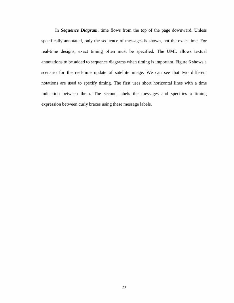
In Sequence Diagram, time flows from the top of the page downward. Unless
specifically annotated, only the sequence of messages is shown, not the exact time. For
real-time designs, exact timing often must be specified. The UML allows textual
annotations to be added to sequence diagrams when timing is important. Figure 6 shows a
scenario for the real-time update of satellite image. We can see that two different
notations are used to specify timing. The first uses short horizontal lines with a time
indication between them. The second labels the messages and specifies a timing
expression between curly braces using these message labels.
24
Figure 6: Sequence Diagram of Updating Satellite Image with Timing Marks
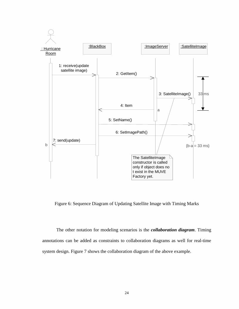
The other notation for modeling scenarios is the collaboration diagram. Timing
annotations can be added as constraints to collaboration diagrams as well for real-time
system design. Figure 7 shows the collaboration diagram of the above example.
: HurricaneRoom
:BlackBox :ImageServer :SatelliteImage
The SatelliteImageconstructor is calledonly if object does not exist in the MUVEFactory yet.
1: receive(updatesatellite image)
7: send(update)b
2: GetItem()
4: Item a
5: SetName()
6: SetImagePath()
{b-a = 33 ms}
3: SatelliteImage() 33 ms
25
{4-2 = 33 ms, 7-4 = 33 ms}
Figure 7: Collaboration Diagram of Updating Satellite Image with Timing Constraints
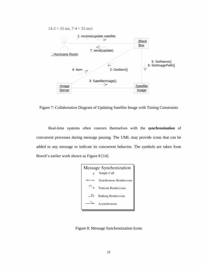
Real-time systems often concern themselves with the synchronization of
concurrent processes during message passing. The UML may provide icons that can be
added to any message to indicate its concurrent behavior. The symbols are taken from
Booch’s earlier work shown as Figure 8 [14].
Figure 8: Message Synchronization Icons
: Hurricane Room
:BlackBox
:ImageServer
:SatelliteImage
1: receive(update satellitei )
2: GetItem()
3: SatelliteImage()
4: Item
5: SetName()6: SetImagePath()
7: send(update)

26
These symbols shown in Figure 8 can be used in conjunction with messages to
indicate how the concurrent processes are synchronized during the message transfer.
• Simple Call - Simple messages denote that the synchronization either has not yet
been specified or is a sequential message (for example, function call semantics).
• Synchronous Rendezvous – A synchronous rendezvous means that the sender will
wait indefinitely for the receiver to accept the message before continuing on with its
processing.
• Timeout Rendezvous. A timeout rendezvous indicates that the sender will wait for the
receiver to be ready for the message up to some fixed period of time before aborting
the message transmission process and continuing on with its processing.
• Balking Rendezvous A balking rendezvous means that if the receiver of the message
is not immediately ready to accept the message, the sender aborts the message and
continues.
• Asynchronous – An asynchronous message means that the sender sends the message
immediately and continues on with processing without waiting for the receiver to
acknowledge its readiness for receiving the message.
Note that current work being done towards developing a Real-Time UML
specification mostly handles real-time operations, including real-time scenario and
message synchronization. But the proposed RT UML specification does not handle real-
time data.

27
2.3.4 Rational Rose Design Tool
Rational Rose is the world’s leading visual modeling tool, which allows users
to define and communicate a software architecture [2]. It provides static and dynamic
views of a logical model and a physical model to capture the in-process products of
object-oriented analysis and design. This overall model contains classes, use cases,
objects, logical packages, operations, component packages, components, processors,
devices and the relationships between them. Each of these model elements possesses
model properties that identify and characterize them. The notation provides graphical
icons to represent each kind of model element and relationship. The model also contains
diagrams and specifications, which provide a means of visualizing and manipulating the
model’s elements and their model properties. In addition, Rational Rose provides the
Interface Design Language (IDL) Code Generator to produce IDL source code from the
information contained in a model. The code generated for each selected model element is
a function of that element's specification, the model's properties, and the model's project
properties. These properties provide the language-specific information required to map
the model into IDL.
A new design tool for embedded real-time system, called Rational Rose
RealTime, has been introduced recently. It is a visual modeling tool with the right
combination of the industry standard Unified Modeling Language, real-time design
constructs, high performance code generation, and model execution. It allows users to
untify their teams by describing the real-time embedded systems using UML, optimize

28
the software development by generating complete, high-performance executables directly
from UML design models targeted to real-time operating systems. This simplifies tool-
chain complexity by providing users with seamless integration to leading real-time
operating systems, compilers, symbolic debuggers, and other market-leading Rational
Software products. However, it is only suitable for embedded real-time systems. It is not
suitable for the dynamic real-time system such as the RT JOVE system.
2.4 Real-time CORBA
Many distributed real-time applications, such as command and control, military
combat system, automated factory control, avionics navigation, and simulation, are
embracing the object-oriented paradigm and have a mandate to use open systems design.
The designers of many of these applications are considering CORBA (See Section 2.1.5)
for their architecture but are finding it is currently inadequate to support real-time
requirements. CORBA contains neither the services, nor the interface facilities to express
and enforce end-to-end timing constraints on distributed client/server interactions.
A real-time Special Interest Group (SIG) has been formed in OMG with the goal
of extending the CORBA standard with support for real-time applications. Specifically,
the real-time SIG is focusing on supporting the ability to enforce end-to-end timing
constraints by extending the current CORBA standard (CORBA/RT). In its white paper
[11], SIG details desired capabilities for extending/modifying CORBA to support real-
29
time. The real-time desired capabilities specified in the CORBA/RT SIG white paper are
classified into three areas: i) desired capabilities for the operating environment, ii) desired
capabilities for the ORB architecture, and iii) desired capabilities for the object services
and facilities.
The Real-time Research group at URI has developed an implementation of RT
CORBA [12]. This work has concentrated on providing support for expressing and
enforcing timing constraints on client/server interactions. This support is implemented
through TDMI’s synchronized clocks, Global Time Service, Global Priority Service, RT
Concurrency Control Service and Real-Time Event Service.
2.5 The RTSORAC Model
RTSORAC (Real-Time Semantic Objects Relationships And Constraints) is a
database model developed by the real-time research group at the URI [5]. This model
supports time-constrained objects and transactions. RTSORAC is comprised of three
components: objects, relationships, and transactions.
Database objects describe the data entities. RTSORAC extends a traditional
object model with five components, <N, A, M, C, CF>, where N is a unique name or
identifier, A is a set of attributes, M is a set of methods, C is a set of constraints, and CF
is a compatibility function. Attributes have name, value, time and imprecision fields.
Objects are also extended to express constraints: logical constraints (on the value fields of

30
attributes), temporal constraints (on the time field of attributes), and bounds on
imprecision (on the imprecision fields of attributes). The compatibility function expresses
the semantics of simultaneous execution of each ordered pair of methods in the objects.
For each ordered pair of methods, (mi, mj), a Boolean expression (BEi,j) is defined. BEi,j
is evaluated to determine whether or not mi and mj can execute concurrently. This
compatibility function may relax the serializability constraint of traditional databases in
order to allow timing constraints to be met. This relaxation may result in the introduction
of imprecision into the object or the transactions that access the object.
In the RTSORAC model, database objects are designed to be kept in shared main
memory for fast, predictable access. Since each transaction may concurrently map objects
in the shared memory segment into its own virtual address space, a concurrency control
mechanism for the shared objects must be provided. The RTSORAC model designers
have developed a concurrency control technique called semantic locking for RTSORAC
object management [13]. The semantic locking technique utilizes the user-defined
compatibility function of a RTSORAC object to determine the trade-off between logical
consistency and temporal consistency, and to define correctness for that particular object.
In this technique, a transaction requests a semantic lock to invoke a method on an object.
Semantic locks are granted based on the evaluation of a set of conditions and on the
evaluation of the compatibility function of the object.
In this section, we have presented background on real-time systems, UML for
real-time and CORBA in this chapter. We have also presented the previous work of this
31
project, including the JOVE system and RTSORAC model. In the next two chapters, we
present the design and implementation of real-time items in the RT JOVE system, the
major contribution of this thesis.

32
Chapter 3
Real-Time Item Design
The design of the RT JOVE system involves adding real-time features to the
JOVE system described in Section 2.1. There are four specific areas in which real-time
features will extend the JOVE architecture: real-time items; real-time CORBA; real-time
database; and real-time scheduling. Figure 9 depicts the real-time extensions that are
being made to the JOVE architecture. Since this project focuses on adding real-time
items into RT JOVE system, this chapter describes how to design real-time items in the
integration of real-time objects into the JOVE system.
JOVEClient
JOVEClient
HTTPDServer CORBA
IIOPCORBAIIOP
MUVEEngineItem
Proxy
Item
Item
ItemFactory
MUVEFactory
MySQLEngine
Objref CORBA
RT RT
RTRT RT
Real-Time
ItemRT
RT
QoS/Scheduling
Service
MySQLDatabase
RT ItemProxy
RTOODB
Figure 9 : RT JOVE Architecture

33
In the current JOVE system, the items that are represented do not have any real-
time features. However, in scenarios such as the hurricane preparedness situation, it may
be necessary to represent real-time data in the system. For instance, a current satellite
image could be maintained and updated periodically so that collaborating users can have
access to the most current information to make decisions. This section describes how we
represent this type of data item. The RTSORAC model described in Section 2.5 provides
a mechanism for representing real-time objects. Therefore we will incorporate the
RTSORAC objects into the RT JOVE MUVE factory to represent the real-time items,
such as the satellite image described above. We will design all the real-time item objects
in the JOVE system using the Rational Rose design tool described in the Section 2.3.4. In
this chapter, we design the general real-time objects using Rational Rose design tool, and
then we apply the general real-time object design to the real-time item design in the RT
JOVE system.
3.1. Design of the General Real-time Objects
The goal of the project is to devise a methodology for designing real-time items in
the system using Rational Rose Design Tool. As stated in Section 2.3.3, there is current
work being done towards developing a Real-Time UML specification for scenario and
message synchronization. But there is little work done for developing a real-time UML
specification for objects. In our design, we apply the RTSORAC objects to design
general real-time objects using the Rational Rose Design Tool.

34
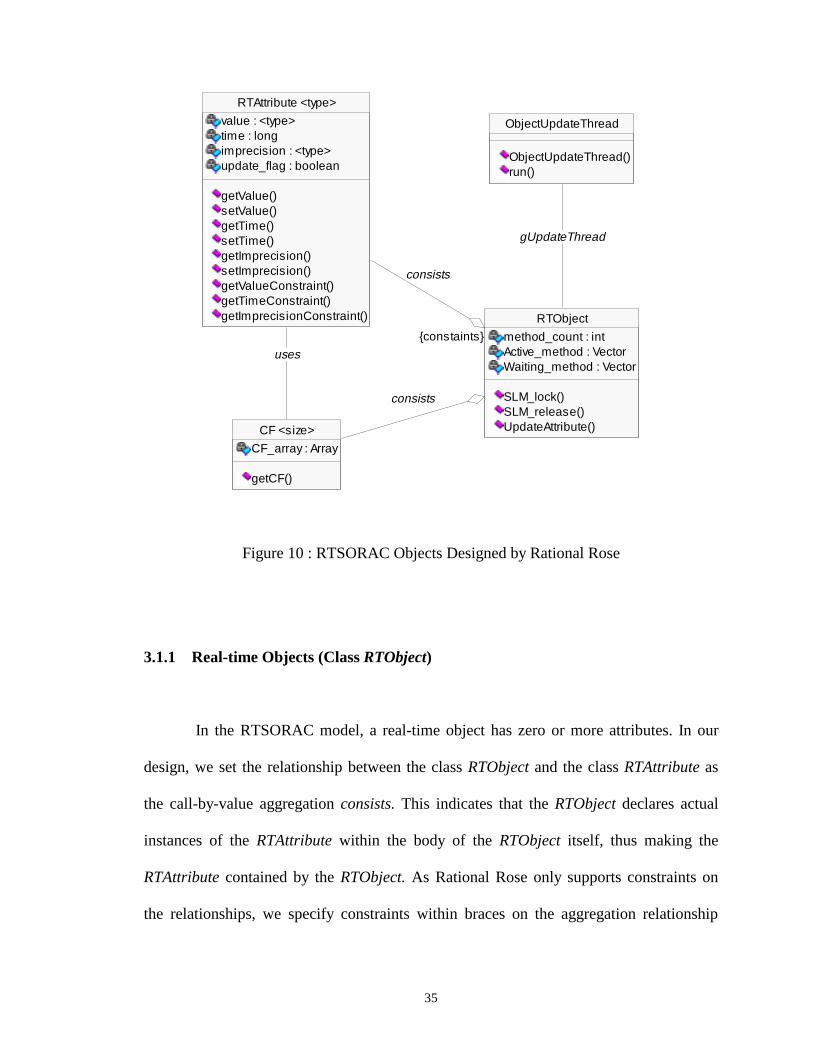
The UML class diagrams that represent the real-time object design are shown in
Figure 10. The class RTObject represents the general real-time objects, the class
RTAttribute represents the real-time attributes, the class CF represents the compatibility
function and the class ObjectUpdateThread represents the thread for updating all the real-
time attributes periodically. The RTObject has a call-by-value aggregation relationship
with the RTAttribute and the CF respectively. A call-by-value aggregation is an
association that is used to show one kind of object is composed of another. The Whole
object declares an actual instance of the Part object within the body of the Whole object
itself, thus making the Part object physically contained by the whole. Thus the RTObject
contains the RTAttribute and the CF physically. The CF has a “uses” association with the
RTAttribute. By using a RTAttribute, the CF can return the current state of the
compatibility functions. And the RTObject has an association with the
ObjectUpdateThread, by which the RTObject can update its real-time attribute
periodically.
35
Figure 10 : RTSORAC Objects Designed by Rational Rose
3.1.1 Real-time Objects (Class RTObject)
In the RTSORAC model, a real-time object has zero or more attributes. In our
design, we set the relationship between the class RTObject and the class RTAttribute as
the call-by-value aggregation consists. This indicates that the RTObject declares actual
instances of the RTAttribute within the body of the RTObject itself, thus making the
RTAttribute contained by the RTObject. As Rational Rose only supports constraints on
the relationships, we specify constraints within braces on the aggregation relationship
RTAttribute <type>
value : <type>time : longimprecision : <type>update_flag : boolean
getValue()setValue()getTime()setTime()getImprecision()setImprecision()getValueConstraint()getTimeConstraint()getImprecisionConstraint()
CF <size>
CF_array : Array
getCF()
uses
ObjectUpdateThread
ObjectUpdateThread()run()
RTObject
method_count : intActive_method : VectorWaiting_method : Vector
SLM_lock()SLM_release()UpdateAttribute()
{constaints}
consists
consists
gUpdateThread

36
between the RTObject and the RTAttribute. In this way, we can express the inter-attribute
timing constraints and logical constraints on the real-time object. For example, the real-
time object Hurricane has two real-time attributes: min_central_pressure and
max_wind_speed for forecast and analysis. We can specify the constraint on the
aggregations as { | min_central_pressure.time – max_wind_speed | < 5 minutes}, which
means that the max_wind_speed should not be more than 5 minutes older than the
min_central_pressure and vice versa.
The class CF<size> is used to obtain the compatibility functions of methods in
the RTObject for concurrency control. It is a parameterized class, which means it is set up
to function independently of the size with which actual classes will work. The parameter
size is specified for the size of the two-dimensioned Boolean array of compatibility
functions for methods. Programmers can define semantic Boolean expressions for the
compatibility functions in the array statically. The class RTObject has a call-by-value
aggregation with the class CF. Thus the RTObject can use the CF to get the compatibility
of object methods in the concurrency control. The method getCF(i, j) returns the value of
the compatibility function of methodi and methodj.
The RTObject uses the thread ObjectUpdateThread to periodically update all real-
time attributes. And the RTObject has the table Active_method for active method
invocations and the table Waiting_method for the blocking method requests. Both tables
are used for the semantic locking concurrency control mechanism.
37
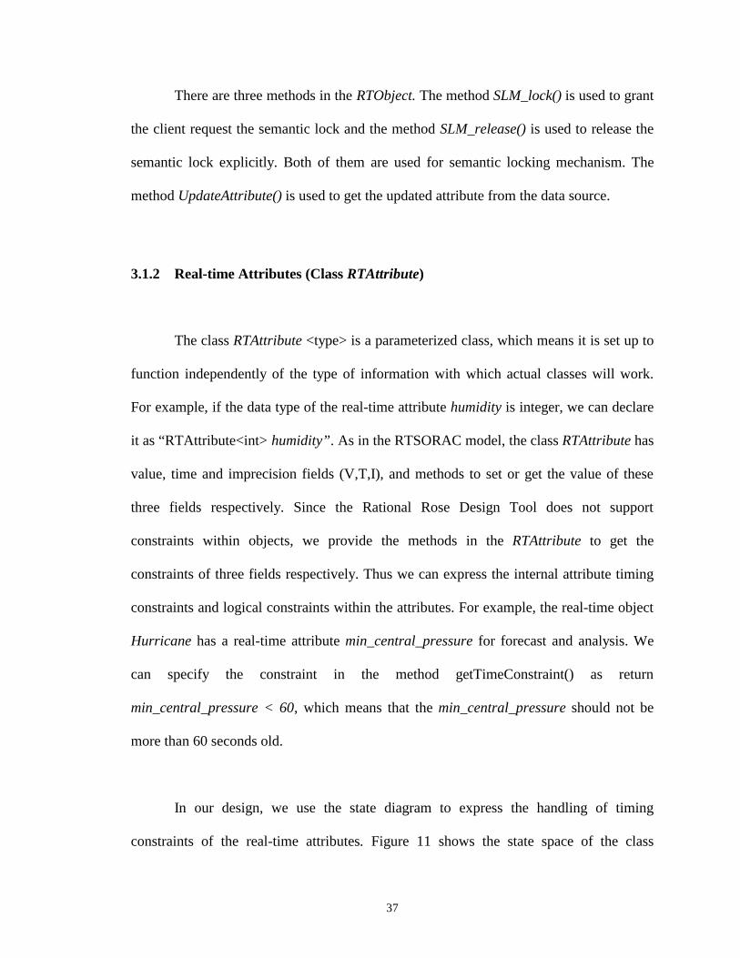
There are three methods in the RTObject. The method SLM_lock() is used to grant
the client request the semantic lock and the method SLM_release() is used to release the
semantic lock explicitly. Both of them are used for semantic locking mechanism. The
method UpdateAttribute() is used to get the updated attribute from the data source.
3.1.2 Real-time Attributes (Class RTAttribute)
The class RTAttribute <type> is a parameterized class, which means it is set up to
function independently of the type of information with which actual classes will work.
For example, if the data type of the real-time attribute humidity is integer, we can declare
it as “RTAttribute<int> humidity”. As in the RTSORAC model, the class RTAttribute has
value, time and imprecision fields (V,T,I), and methods to set or get the value of these
three fields respectively. Since the Rational Rose Design Tool does not support
constraints within objects, we provide the methods in the RTAttribute to get the
constraints of three fields respectively. Thus we can express the internal attribute timing
constraints and logical constraints within the attributes. For example, the real-time object
Hurricane has a real-time attribute min_central_pressure for forecast and analysis. We
can specify the constraint in the method getTimeConstraint() as return
min_central_pressure < 60, which means that the min_central_pressure should not be
more than 60 seconds old.
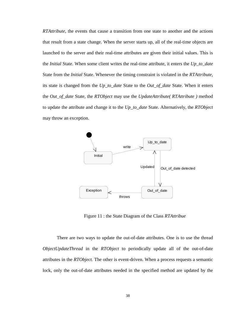
In our design, we use the state diagram to express the handling of timing
constraints of the real-time attributes. Figure 11 shows the state space of the class
38
RTAttribute, the events that cause a transition from one state to another and the actions
that result from a state change. When the server starts up, all of the real-time objects are
launched to the server and their real-time attributes are given their initial values. This is
the Initial State. When some client writes the real-time attribute, it enters the Up_to_date
State from the Initial State. Whenever the timing constraint is violated in the RTAttribute,
its state is changed from the Up_to_date State to the Out_of_date State. When it enters
the Out_of_date State, the RTObject may use the UpdateAttribute( RTAttribute ) method
to update the attribute and change it to the Up_to_date State. Alternatively, the RTObject
may throw an exception.
Figure 11 : the State Diagram of the Class RTAttribue
There are two ways to update the out-of-date attributes. One is to use the thread
ObjectUpdateThread in the RTObject to periodically update all of the out-of-date
attributes in the RTObject. The other is event-driven. When a process requests a semantic
lock, only the out-of-date attributes needed in the specified method are updated by the
Out_of_date
Initial
Up_to_date
Exception
write
Out_of_date detectedUpdated
throws
39
method UpdateAttribute(). The periodic update is used to make the real-time attributes as
up-to-date as possible so that the processes need not update attributes and thus uses less
time to complete the method execution. But if the periodic update is too often and
unnecessary, the overload will increase greatly and thus lower the performance.
Therefore there is a tradeoff between these two options and the tradeoff is object-specific.
We will let the users specify the period for update of individual attributes in an object,
and choose one of the following ways for the period: maximum, minimum, average and
median. For example, if the user set the periods of four attributes as 20 seconds, 30
seconds, 60 seconds and 10 seconds, then the period of the objects is 60 seconds if the
user chooses maximum option, 10 seconds for the minimum option, 30 seconds for the
average option, or 25 seconds for the median option. In this way, we provide great
flexibility to users to specify the update periods of objects with a better real-time
performance.
3.1.3 Semantic Locking Object Concurrency Control
Concurrency allows multi-tasks in a software application to run at the same time
and thus greatly improve the efficiency. It is especially beneficial to real-time
applications because concurrency greatly increases the chances for tasks to meet their
timing constraints. Therefore we add concurrency to the JOVE system for better
performance as the JOVE system is a single-process application. Concurrency control is
an important part of this project when multiple tasks request the shared resources.
40
The concurrency control technique called semantic locking is capable of
supporting data logical consistency and data temporal consistency, and expressing the
tradeoffs between them (See Section 2.5). We will use it as the concurrency control in the
RT JOVE system. Each real-time object has its own semantic locking mechanism. The
concurrency control mechanism of each object uses semantic locking to enforce the
allowable concurrency expressed by the compatibility function of the object. A process
request for a real-time object must acquire a semantic lock for a method invocation
before the method is allowed to execute.
When a client requests for a method invocation mreq of the real-time object
RTObject, the semantic locking mechanism will first call the SLM_lock() method in the
RTObject to get the semantic lock, specifying the method, subset of real-time attributes
used by the method and the arguments for the requested invocation. The SLM_lock()
acquires the mutex for access to the tables Active_method and Waiting_method in the
RTObject. When the mutex is granted, the SLM_lock() attempts to acquire a semantic
lock for the request. There are two possible outcomes when a process requests a semantic
lock for a method invocation: the SLM_lock() either grants permission to the process to
execute the requested method, or it suspends the requesting process. A suspended
transaction will be awakened and will retry its lock request whenever a lock is released.
In either case, the transaction releases the mutex at the end of the SLM_lock(). Note that
the server uses mutexes to ensure mutual exclusion only for each real-time object’s tables
during the semantic locking mechanism execution. Access to object attributes is

41
controlled with semantic locks. In this way, it increases the concurrency and thus
improves the real-time performance.
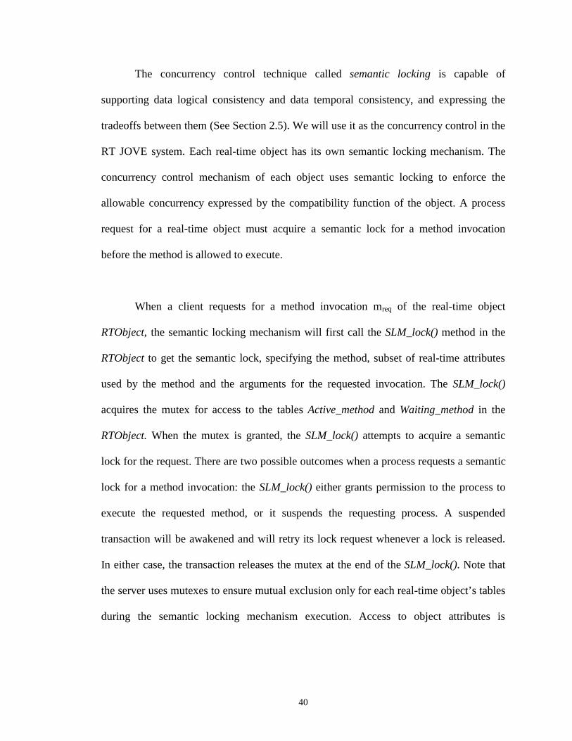
The RTObject uses its methods SLM_lock() and SLM_release() to control
concurrency. The method SLM_lock() is used for mreq to obtain the semantic locking
shown in the sequence diagram of Figure 12. When the SLM_lock() is called, it will call
the method checkAttribute() to evaluate the subset of attributes used in the mreq and see if
they are up-to-date. If some or all of this subset of attributes are out-of-date, it will call
the method UpdateAttribute() in the RTObject to update them. Then the SLM_lock() will
call the method checkCF() in the RTObject to evaluate the compatibility function for mreq
with each currently locked method invocation and with each blocking request in the
waiting queue for a method invocation with higher priority than mreq. If all compatibilities
are valid, then the SLM_lock() will call the method addActiveTable() to add mreq to the
table for the currently active methods and grant the semantic lock to the mreq. Otherwise
it will call the addWaitingTable() to add mreq to the table for the waiting methods block
the mreq.
42
Figure 12 : Sequence Diagram of SLM_lock()
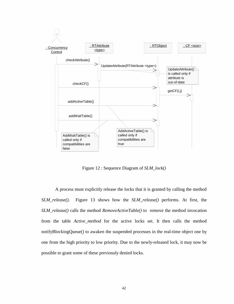
A process must explicitly release the locks that it is granted by calling the method
SLM_release(). Figure 13 shows how the SLM_release() performs. At first, the
SLM_release() calls the method RemoveActiveTable() to remove the method invocation
from the table Active_method for the active locks set. It then calls the method
notifyBlockingQueue() to awaken the suspended processes in the real-time object one by
one from the high priority to low priority. Due to the newly-released lock, it may now be
possible to grant some of these previously denied locks.
: RTAttribute<type>
: ConcurrencyControl
: CF <size> : RTObject
checkAttribute()
UpdateAttribute()is called only ifattribute isout-of-date
UpdateAttribute(RTAttribute <type>)
checkCF()
getCF(i,j)
addActiveTable()
AddActiveTable() iscalled only ifcompatibilities aretrue
addWaitTable()
AddWaitTable() iscalled only ifcompatibilities arefalse
43
Figure 13 : Sequence Diagram of SML_release()
3.2 Design of the Real-time Items for the RT JOVE System
In the RT JOVE system, real-time items not only have the characteristics of items
in the JOVE system, but also have the real-time features. Thus we will apply the general
real-time object model described in Section 3.1 to the items in the JOVE system for the
real-time item design.
3.2.1 Information Items Design in the JOVE System
Information items are the core of the entire virtual environment system. Every
item within the system can be described as an object including the system itself. Items
notifyBlockingQueue()
addActiveTable() : Concurrency Control
: RTObject
removeActiveTable()

44
may contain any type of information, including multimedia content, as well as their own
“verbs” describing their actions and interactions. For example, the room item named
Emergency Planning Project Room in the JOVE system contains the project schedule
item whose type is “Briefing”.
The object base in the JOVE system is extended to include a CORBA interface.
This will allow access to fully distributed objects which adhere to the CORBA standards
as well as enable access other databases, such as ORACLE or Sybase.
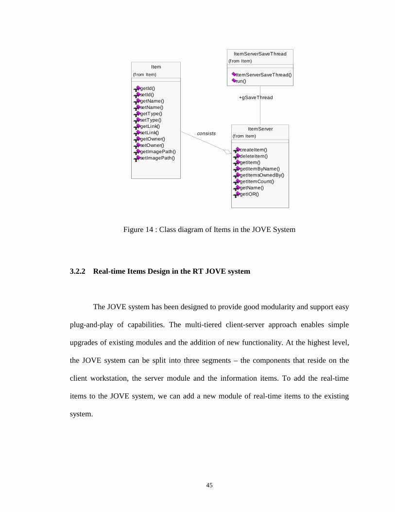
In the JOVE system, the object ItemServer consists of multiple object Items and
their relationship is aggregation. The object ItemServer is responsible for creating and
deleting an item object, and getting the specified Item object reference shown as Figure
14. The object ItemServer has the thread to periodically save changed items to database.
45
Figure 14 : Class diagram of Items in the JOVE System
3.2.2 Real-time Items Design in the RT JOVE system
The JOVE system has been designed to provide good modularity and support easy
plug-and-play of capabilities. The multi-tiered client-server approach enables simple
upgrades of existing modules and the addition of new functionality. At the highest level,
the JOVE system can be split into three segments – the components that reside on the
client workstation, the server module and the information items. To add the real-time
items to the JOVE system, we can add a new module of real-time items to the existing
system.
+gSaveThread
Item
getId()setId()getName()setName()getType()setType()getLink()setLink()getOwner()setOwner()getImagePath()setImagePath()
(f rom Item)
ItemServer
createItem()deleteItem()getItem()getItemByName()getItemsOwnedBy()getItemCount()getName()getIOR()
(f rom Item)
ItemServerSaveThread
ItemServerSaveThread()run()
(f rom Item)
consists
46
Figure 15 shows the real-time item design by integrating the general real-time
object design described in Section 3.1 and the item design described in Section 3.2.1. The
Object RTItem represents the real-time items, the object Item represent the existing item
in the JOVE system, the object ItemServer represents the item server and the object
RTObject represents the general real-time objects. The object RTItem is designed to
inherit from the object Item and the object RTObject since the Rational Rose supports
multiple inheritance. Thus the object RTItem includes the same attributes and methods as
the object Item and as the object RTObject. The object RTItem not only has the non-real-
time attributes and the methods using only non-real-time attributes defined in the Item,
but also the real-time attributes defined and methods using one or more real-time
attributes in the RTObject. When the client requests a non-real-time method in the
RTItem, the server will invoke this method as that did in the Item. And when the client
requests a real-time method in the RTItem, the server will invoke the semantic locking
mechanism for concurrency control and then grant the semantic lock and invoke the
method in the RTItem as that did in the RTObject. In a word, the object RTItem is a
combination of the object Item and the object RTObject.
The object RTItemServer consists of multiple RTItem objects. The RTItemServer
is responsible for creating, deleting, getting and periodically saving the RTItem objects.
In this way, we can quickly and easily add new real-time features to the JOVE
system without changing the existing features or capabilities. We also reuse the existing
module in the new capabilities.

47
Figure 15 : Class Diagram of Real-time Item in the RT JOVE System
RTAttribute <type>
value : <type>time : longimprecision : <type>update_flag : boolean
getValue()setValue()getTime()setTime()getImprecision()setImprecision()getValueConstraint()getTimeConstraint()getImprecisionConstraint()
CF <size>
CF_array : Array
getCF()
uses
ObjectUpdateThread
ObjectUpdateThread()run()
RTObject
method_count : intActive_method : VectorWaiting_method : Vector
SLM_lock()SLM_release()UpdateAttribute()
{constraints}
consists
consists
gUpdateThread
RTItem
getId()setId()getName()setName()getType()setType()getLink()setLink()getOwner()setOwner()getImagePath()setImagePath()
extends
RTItemServerSaveThread
RTItemServerSaveThread()run()
RTItemServer
createItem()deleteItem()getItem()getItemByName()getItemsOwnedBy()getItemCount()getName()getIOR()
consists
gSaveThread
Item
getId()setId()getName()setName()getType()setType()getLink()setLink()getOwner()setOwner()getImagePath()setImagePath()
consists
extends

48
Chapter 4
Real-Time Item Implementation
In this chapter we will describe the implementation of the real-time objects in the
RT JOVE system based on the design presented in Chapter 3. The first section describes
the migration of the RT JOVE system to support CORBA in Java. The second section
presents how the RTSORAC object is incorporated into the RT JOVE system in full
details.
4.1 Migration of the RT JOVE System
The current JOVE system uses CORBA for communication between the client
and the MUVE Server, and its CORBA implementation is Java IDL. In the real-time
implementation, we use Java IDL to implement the real-time objects in the RT JOVE
system.
49
4.1.1 Define and Compile the IDL Interface
To develop the Java IDL, we define the interface for the remote object using the
OMG’s interface definition language. We use IDL instead of the Java language because
the idltojava compiler automatically maps from IDL, generating all Java language stub
and skeleton source files, along with the infrastructure code for connecting to the ORB.
For example, we define the remote object ItemServer using the IDL as following:
#pragma javaPackage "com.saic.MUVE.Realtime"
interface ItemServer
{
Item createItem (in string name, in string type, in string
link, in string path, in long long owner, in long long location,
in string description);
void deleteItem (in long long id);
Item copyItem (in long long id);
Item getItem (in long long id);
Item getItemByName (in string name);
Items getItemsByOwner(in long long owner);
Items getItemsByLocation(in long long location);
Names getItemNames ();
Types getItemTypes ();
long long getItemCount ();
ItemServer getItemServer();
string getName ();
50
string getIOR ();
};
When we run the idltojava compiler over this interface definition file
ItemServer.idl, it generates five files, including the Java version of the interface
ItemServer.java, the server skeleton _ItemServerImplBase.java, the client stub
_ItemServerStub.java, and two auxiliary files ItemServerHolder and ItemServerHelper.
4.1.2 Implement the IDL Interface
There are two mechanisms for implementing an IDL interface: the ImBase
approach and the TIE approach.
• The ImplBase Approach
The ImplBase [17] approach is also called the inheritance approach. In the
ImplBase approach, we create a Java class that inherits from the corresponding ImplBase
class (server skeleton) to indicate it implements a given IDL interface. Each ImplBase
class is the Java equivalent of an IDL interface. Therefore a class that inherits from the
ImplBase class implements the operations of the corresponding IDL interface. For
example, we define the class ItemServerServant that inherits from the abstract class
_ItemServerImplBase (server skeleton) to implement the CORBA interface for the
ItemServer shown in the Figure 16.

51
Figure 16 : Class Diagram of ItemServer Java IDL Implementation
Using ImplBase Approach
• The TIE Approach
The TIE approach is also called the delegation approach. To use the TIE
approach, we need to compile the IDL interface with the flag –ftie in the command. The
idltojava compiler generates two additional files: Operations.java and Tie.java. In the
ItemServerHelper
ItemServerHelper()__write()__read()extract()insert()type()id()_is_a()narrow()
(f rom Item)
ItemServer
createItem()deleteItem()getItem()getItemByName()getItemsOwnedBy()getItemCount()getName()getIOR()
(f rom Item)
<<Interface>>
ItemServerHolder
ItemServerHolder()ItemServerHolder()__write()__read()__type()
(f rom Item)
+value
ItemServerSaveThread
ItemServerSaveThread()run()
(f rom Item)_ItemServerStub
_ItemServerStub()_get_operations()_get_ids()createItem()deleteItem()getItem()getItemByName()getItemsOwnedBy()getItemCount()getName()getIOR()
(f rom Item)
_ItemServerImplBase
_get_dispatch_table()_ItemServerImplBase()_get_ids()_execute()_execute()
(from Item)
ItemServerServant
ItemServerServant()ItemServerServant()getItem()getItemByName()getItemsOwnedBy()createItem()deleteItem()getItemServer()getItemCount()getName()getIOR()getConnection()save()
(f rom Item)
-$gItemServer
extends
gSaveThread

52
TIE approach, we implement the IDL operations and attributes in a class which does not
inherit from the automatically generated ImplBase class. Instead, this approach uses the
automatically generated Java TIE class in the file Tie.java to tie together the
implementation class and the IDL interface. We define a new class that must implement
the Java interface Operations in the file Operations.java. Figure 17 shows how to use the
tie approach to implement the IDL interface ItemSserver. We define the class
ItemServerServant to implement the automatically generated interface
_ItemServerOperations. Then we instantiate an object of type _ItemServerTie, passing an
object of type ItemServerServant to the constructor. A TIE object is thus created which
delegates incoming operation invocations to the methods of the ItemServerServant object
as following:
ItemServerServant servant = new ItemServerServant();
ItemServer ItemServerRef = new _ItemServerTie(servant);

53
Figure 17 : Class Diagram of ItemServer Java IDL Implementation
Using TIE Approach
• Comparison of the ImplBase and TIE Approach
Both the TIE and ImplBase approaches to interface implementation allow us to
provide a number of different implementation classes for the same IDL interface. This is
_ItemServerTie
createItem()deleteItem()getItem()getItemByName()getItemsOwnedBy()getItemCount()getName()getIOR()
ItemServer
createItem()deleteItem()getItem()getItemByName()getItemsOwnedBy()getItemCount()getName()getIOR()
(f rom Item)
<<Interface>>
ItemServerHolder
ItemServerHolder()ItemServerHolder()__write()__read()__type()
(f rom Item)+value
ItemServerHelper
ItemServerHelper()__write()__read()extract()insert()type()id()_is_a()narrow()
(f rom Item)
_ItemServerImplBase
_get_dispatch_table()_ItemServerImplBase()_get_ids()_execute()_execute()
(from Item)
ItemServerServant
ItemServerServant()ItemServerServant()getItem()getItemByName()getItemsOwnedBy()createItem()deleteItem()getItemServer()getItemCount()getName()getIOR()getConnection()save()
(f rom Item)
-$gItemServer
_ItemServerOperations
createItem()deleteItem()getItem()getItemByName()getItemsOwnedBy()getItemCount()getName()getIOR()
<<Interface>>_ItemServerStub
createItem()deleteItem()getItem()getItemByName()getItemsOwnedBy()getItemCount()getName()getIOR()deleteItem()getItem()getItemByName()getItemsOwnedBy()getItemCount()getName()getIOR()
(f rom Item)

54
an important feature, especially in a large heterogeneous distributed system. An object
can then be created as an instance of any one of the implementation classes. Client
programmers do not need to be aware of which implementation class is used.
The ImplBase and TIE approaches to interface implementation impose similar
overheads on the implementation programmer. However, there are two significant
differences, which may affect the choice of implementation strategy:
• The ImplBase approach requires the implementation class to extend a
generated base class, while the TIE approach merely requires the
implementation of a Java interface.
• The TIE approach requires the creation of an additional object for each
implementation object instantiated in a server.
Java does not support multiple inheritance for classes. So the inheritance
requirement which the ImplBase approach imposes on implementation classes limits the
flexibility of those classes and eliminates the possibility of reusing existing
implementations when implementing derived interfaces. The TIE approach does not
suffer from this restriction.
The creation of a TIE object for each implementation object may be a significant
factor in applications where a large number of implementation objects are created and

55
tight restrictions on the usage of virtual memory exists. In addition, the delegation of
client invocations by TIE objects implicitly involves an additional Java method
invocation for each incoming request.
Thus, we need not choose one approach exclusively, as both can be used within
the same server.
4.1.3 Implement Multiple Inheritance
In the design of real-time objects in the RT JOVE system described in Section 3,
the real-time class RTItem inherits from the general real-time object class RTObject and
the existing class Item in the JOVE system. Thus we need to implement the multiple
inheritance for the real-time items in the Java IDL.
IDL allows us to define a new interface by extending the functionality provided
by an existing interface. IDL also supports multiple inheritance, which allows an
interface to have several immediate base interfaces. However, Java only supports
multiple inheritance of interfaces, but it does not support multiple inheritance of classes.
Consequently, each generated Java class implements all the methods of the corresponding
Java interface and of all interfaces from which it inherits.
56
Using the ImplBase approach, the implementation class RTItemServant of type
RTItem must inherit from class _RTItemImplBase and directly implement all methods for
interface RTItem and all types – RTObject and Item – from which it inherits.
Using the TIE approach, the implementation class RTItemServant must implement
Java interface _RTItemOperations, but may inherit the implementation methods from the
existing class Item in the JOVE system. However, the absence of support for multiple
inheritance of classes in Java implies that a multiple inheritance hierarchy of IDL
interfaces can never map directly to the implementation classes for those interfaces.
The current version of JOVE system is developed using the JDK1.1.7 and the
early release of Java IDL. With this early version, the early release of Java IDL compiler
does not support the TIE approach. Thus, in this project, we use the ImplBase approach
to implement the real-time items. The IDL interface RTItem defines all the required
methods, including the non-real-time methods defined in the interface Item, and the real-
time methods needed for itself. The implementation class RTItemServant inherits from
the generated class _RTItemImplBase. It implements the all the methods in the IDL
interface RTItem and the methods in the general real-time object RTObject, including the
methods SLM_lock(), SLM_release(), UpdateAttribute() for the semantic locking
mechanism and update of real-time attributes.
57
4.2 Implementation of Real-time Item
Real-time items in the RT JOVE system are scenario-specific. For example, we
can define the real-time item Hurricane in the hurricane meeting scenario. Thus different
real-time items have different real-time attributes and compatibility functions. As
described in the Section 3, the real-time item also has a semantic locking mechanism for
concurrency control. There are three parts of the implementation: real-time attributes,
compatibility functions and semantic locking mechanism. This section describes how to
implement the incorporation of the RTSORAC objects into the RT JOVE system. We
also go through the example how to implement the real-time item Hurricane in the RT
JOVE system.
4.2.1 Real-time Attributes
We define an interface RTAttribute for the real-time attributes as the following:
package com.saic.MUVE.Realtime;
public interface RTAttribute
{public Object getValue();
public void setValue(Object value);
public long getTime();
public void setTime(long time);
public Object getImprecision();
public void setImprecision(Object imprecision);
public boolean getValueConstraint();

58
public boolean getTimeConstraint();
public boolean getImprecisionConstraint();
public String getSource();
}
The interface RTAttribute defines ten methods. The first six methods are used to
set and get the value, time and imprecision fields, and get their constraints as described in
the Section 3.1.2. The final method getSource() is used to get the update source. In this
project, all the persistent sources for real-time attributes are the corresponding files.
When there is a need for updating a real-time attribute, the real-time item needs to call
the method getSource() to get the source file name. In the future RT JOVE system, we
will replace these files with a real-time database to store all the real-time attributes.
We can define a real-time attribute to implement the interface RTAttribute. For
example, we define a real-time attribute Wind_speed to implement the interface
RTAttribute as the following. In the code, we specify the timing constraint on the
getTimeConstraint() that the Wind_speed can not be older than 20 seconds.
Public Class Wind_speed implements RTAttribute
{private Object value = null;
private long time = 0;
private Object imprecision = null;
private String file_name;
.
.
//define the timing constraint of Wind_speed

59
public boolean getTimeConstraint () {
long current_time = (System.currentTimeMillis() %
1000000000) /1000;
long start_time = time;
return current_time - start_time < 20 ;
}
.
.
}
In this way, programmers have great flexibility to specify the timing constraints
on the real-time attributes.
4.2.2 Compatibility Function
Compatibility functions are used to control concurrency. We define an interface
CF for the Compatibility functions as the following:
package com.saic.MUVE.Realtime;
public interface CF
{
boolean getCF(int i, int j);
}
The method getCF(int i, int j) is used to get the concurrent compatibility of the
two methods. Programmers can define semantic Boolean expressions for the

60
compatibility functions in the array statically. For example, there are just two methods
using this real-time attribute Wind_speed in the real-time item Wind: write_speed() and
read_speed(). The method void write_speed(int) is used to write integer parameter to the
value of the Wind_speed, and the method int read_speed() is used to return the integer
value of the Wind_speed. We can define the class wind_cf to implement the interface CF
for the real-time item Wind as the following:
class wind_cf implements CF {
boolean[][] comp_func = new boolean[2][2];
public wind_cf () {
// specify the semantic Boolean expressions for compatibility functions
comp_func[0][0] = false;
comp_func[0][1] = false;
comp_func[1][0] = false;
comp_func[1][1] = true;
}
public boolean getCF(int i, int j) {
return comp_func[i][j];
}
In the code above, we specify that we can read the real-time attribute Wind_speed
concurrently only in the real-time item Wind because we define the last compatibility
function as true while others are false. In this way, programmers have great flexibility to
specify the compatibility functions for real-time items.

61
4.2.3 Semantic Locking Mechanism
In the RT JOVE system, we provide a concurrent environment for client requests
to improve the real-time performance. Java is inherently multi-threaded. A single Java
program can have many different threads executing independently and continuously.
Thus, we implement the concurrent processing using the multi-thread mechanism in Java.
When several threads want to access the shared resources such as variables, we
need the concurrency control mechanism. Each Java object has a lock. This lock can be
used as an implicit binary semaphore in a block of code synchronized on the object. To
execute synchronized code on an object, a thread must own the object’s lock. When two
threads execute code synchronized on the same object, only one of them acquires the lock
and proceeds. The other is paused until the first one releases the lock. If obj is a reference
to some object, then obj is used as an implicit binary semaphore in the following way.
synchronized (obj) {
block of code, e.g. critical section;
}
Any object can be used in a synchronized block as an implicit binary semaphore.
In the semantic locking mechanism as designed in the Section 3.1.3, each real-
time item object has its own semantic locking mechanism, including the method
SLM_lock(), the thread SLM_release and the method updateAttribute().

62
4.2.3.1 the Method SLM_lock()
The method SLM_lock() in each real-time item is used to grant semantic locks to
the client request for method invocation. The method SLM_lock() uses the binary
semaphore. We define the method SLM_lock() synchronized as the following:
public synchronized boolean SLM_lock(int id, Thread
current_thread, int priority, RTAttribute[] rtattr, boolean
new_thread) {
.
.
//update out-of-date real-time affected attributes
for (int i=0; i< attr_size ; i++)
if (!rtattr[i].getTimeConstraint())
updateAttribute(rtattr[i]);
//check the CF of the current method and active methods
synchronized (gActiveMethodTable) {
int active_table_size = gActiveMethodTable.getLength();
while (compatible && j < active_table_size)
{compatible = gCompFunc.getCF
(gActiveMethodTable.getId(j), id);
j++;
}
}
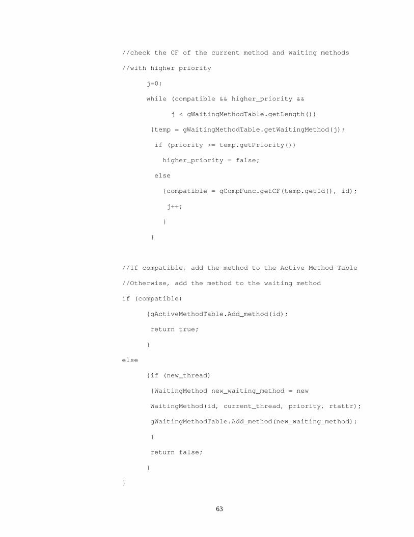
63
//check the CF of the current method and waiting methods
//with higher priority
j=0;
while (compatible && higher_priority &&
j < gWaitingMethodTable.getLength())
{temp = gWaitingMethodTable.getWaitingMethod(j);
if (priority >= temp.getPriority())
higher_priority = false;
else
{compatible = gCompFunc.getCF(temp.getId(), id);
j++;
}
}
//If compatible, add the method to the Active Method Table
//Otherwise, add the method to the waiting method
if (compatible)
{gActiveMethodTable.Add_method(id);
return true;
}
else
{if (new_thread)
{WaitingMethod new_waiting_method = new
WaitingMethod(id, current_thread, priority, rtattr);
gWaitingMethodTable.Add_method(new_waiting_method);
}
return false;
}
}

64
The method SLM_lock() is called when a real-time method is requested to be
invoked by a client or by the thread SLM_release for the blocked threads in the waiting
table. It takes the method id, the thread that called the SLM_lock(), the priority, the
affected real-time attribute set and the Boolean flag that tells if the thread is a new thread
or a blocking thread in the waiting table as its parameters. It updates the affected real-
time attributes if necessary, then it checks the compatibility of the method with the active
methods, and the compatibility of the method with the blocked methods with higher
priority in the waiting table. Finally, SLM_lock returns true if the method can be granted
a semantic lock based on method compatibilities and false if not.
4.2.3.2 the Thread SLM_release
When a method thread is going to finish, it must explicitly release the lock by
creating a thread SLM_release(). We use a thread instead of a method to implement the
explicit release of a semantic lock because a thread provides more concurrency, and thus
dramatically boosts its performance. The following is the implementation of the Thread
SLM_release.
class SLM_release_thread extends java.lang.Thread {
private int method_id;
//constructor
public SLM_release_thread (int id)
{

65
super ("SLM_release_thread");
method_id = id;
this.start ();
}
public void run ()
{WaitingMethod temp = null;
//remove the method from the active method table
synchronized (gActiveMethodTable) {
gActiveMethodTable.Remove_method(method_id);
}
int size = gWaitingMethodTable.getLength();
//Synchronizing
java.lang.Object release_mutex = new java.lang.Object();
int i = 0;
synchronized (release_mutex) {
while (i<size)
{temp=(WaitingMethod)
gWaitingMethodTable.getWaitingMethod(i);
if (SLM_lock(temp.getId(), temp.getThread(),
temp.getPriority(), temp.getAttr(), false))
{
//compatible
temp.getThread().resume();
gWaitingMethodTable.Remove_method(i);
size = gWaitingMethodTable.getLength();
66
}
else //not compatible
{i++;
}
}
}
}
} //class end
The thread SLM_release inherits from the class Thread. When the SLM_release is
created by a method thread, it removes the method from the active method table first.
Then it calls the method SLM_lock() to check the compatibility of all the waiting method
threads from the highest priority to the lowest priority. If it is compatible, the
SLM_release removes it from the waiting method table, grants it the semantic lock and
resumes the suspended method thread.
4.2.3.3 the Method updateAttribute
The updateAttribute() method is used to update real-time attributes if they are out-
of-date. Up-to-date data may be provided by a real-time database, a file or a program.
There may be different ways to update real-time attributes if the sources of real-time
attributes are different. In this project, the sources of real-time attributes are files. When
we need to update the real-time attributes, the method updateAttribute() will read the up-
to-date data from the file and assign it to the real-time attributes. The following is the
implementation of the method updateAttribute() for an integer real-time attribute.

67
public void updateAttribute(RTAttribute attr) {
try {
synchronized(this) {
File temp_File = new File(attr.getFile_name());
FileInputStream fis = new FileInputStream(temp_File);
byte[] buf = new byte[100];
int n = fis.read(buf);
String temp_string = new String(buf);
Integer temp_int = new Integer(temp_string.trim());
attr.setValue(temp_int);
attr.setTime((System.currentTimeMillis()%1000000000)
/1000);
}
} catch(Exception e) {
System.err.println("ERROR: " + e);
e.printStackTrace(System.out);
}
}
The method updateAttribute() takes the RTAttribute as the parameter. At first it
obtains the source file name from this real-time attribute. Then it reads the updated data
from the file and assigns it to the value of the real-time attribute. Finally it resets the time
of the real-time attribute to the current time.

68
4.2.3.4 the Real-time Method
A real-time method here is defined as a method that uses one or more real-time
attributes. When a client requests a real-time method invocation, the real-time item server
will create the corresponding real-time method thread. In this way, the RT JOVE system
allows concurrent processing. The following is an example to implement a real-time
method.
public int read_wind_speed (int priority)
{
//start the read Thread for real-time attribute wind_speed
read_wind_speed_Thread temp_thread = new read_wind_speed_Thread
(priority);
//get the value of wind_spreed
return temp_thread.getResult();
}
In this example, the method read_wind_speed() is used to read the real-time
attribute Wind_speed. When it is executed, it creates a corresponding thread
read_wind_spreed_Thread() and then returns the result by calling the method getResult()
in the read_wind_spreed_Thread. The read_wind_spreed_Thread() is implemented as
the following:
class read_wind_speed_Thread extends java.lang.Thread {

69
private int priority = 0;
private RTAttribute rt_attr[] = {count1};
private int temp_wind_speed;
//constructor
public read_wind_speed_Thread (int cpriority)
{
super ("Read_wind_speed_thread");
priority = cpriority;
rt_attr[0] = Wind_speed;
this.start ();
}
public void run ()
{
//get the semantic lock of this thread. If it fails,
//suspend this thread
if (!SLM_lock(2, this, priority, rt_attr, true))
this.suspend();
temp_wind_speed = ((Integer)
Wind_speed.getValue()).intValue();
//release the semantic lock
SLM_release_thread temp_slm_thread = new SLM_release_thread
(2);
}
int getResult () {

70
try{ //wait until the thread terminates
join();
}
catch (Exception e) {
System.err.println("ERROR: " + e);
e.printStackTrace(System.out);
}
return temp_wind_speed;
}
} //class end
The thread read_wind_speed_Thread() inherits the class Thread. It takes the
priority as its parameter for the constructor. In the method run(), it first tries to get the
semantic lock by calling the method SLM_lock(). If it gets the semantic lock, it will go
ahead to read the value of the real-time attribute Wind_speed. Otherwise, it will suspend
itself and wait for some active threads that are not compatible with it to finish. After it
reads the value of Wind_speed, it starts the thread SLM_release to release its semantic
lock. In the method getResult(), the method join() is used for synchronization. The
getResult() waits for the this thread to finish by calling the method join(). Then it returns
the value of Wind_speed.
4.2.4 Real-time Item Server
The real-time item server is responsible for creating, deleting and getting real-
time items. Since there are different types and numbers of real-time attributes in different
71
types of real-time items, it is hard to implement a general real-time item server to
maintain different types of real-time items. Therefore in this project, we implemented
separate real-time servers for different types of real-time items instead of just a single
real-time server. For example, the real-time item type Hurricane has its own server
HurricaneServer. The real-time item server is used to manage its own real-time items.
When the RT JOVE system is started, the real-time item server launches its own real-
time items from MySQL database.
The separate real-time server is responsible for the creation, deletion and
obtaining of its own real-time items. Since different types of real-time items have
different timing constraints, we use a thread RTItemServerSaveThread in each type of
real-time server instead in the MUVE server to save all the objects of its real-time items
periodically. Thus we can define different periods for saving in different types of real-
time item servers. For example, the HurricaneServer may save all Hurricane items
every 30 seconds while the SatelliteImageServer may save all SatelliteIamge items every
10 minutes.
The implementation of saving thread in the real-time item server is very similar to
that of the non-real-time item server existing in the JOVE system. Thus we can reuse
most of its codes. For example, we implemented a real-time item Hurricane and its server
HurricaneServer in the RT JOVE system. In the HurricaneServant for the real-time item
Hurricane, we have the method save() to save the changed attributes within it. And in the
HurricaneServerServant for the real-time item server HurricaneServer, we have a thread

72
RTItemServerSaveThread to save all the Hurricane items periodically. In the existing
implementation of MUVE server MuveServerServant, we add a creation of the
HurricaneServer. When we run the MUVE server, it will create an object of the
HurricaneServerServant and then start a RTItemServerSaveThread thread for periodically
saving all changed attributes of all Hurricane items.

73
Chapter 5
Real-Time Item Evaluation
In this chapter we present three groups of tests that indicate the correctness of our
design and implementation. One test is for periodically saving attributes into the
database, one is for updating real-time attributes, and one is for the semantic locking
mechanism for concurrency control to ensure the runtime correctness of the
implementations. To test the correctness of our design and implementation, we added a
real-time item Hurricane with two real-time attributes Wind_speed and Central_pressure
and its real-time item server HurricaneServer to the JOVE system. We also wrote several
client programs to request real-time methods of Hurricane. We created a real-time
environment in the JOVE system by running the clients with priorities and tested the
correctness of these three groups of tests.
5.1 Testing the Saving Thread for Real-time Attributes
Each real-time item in the RT JOVE system has a thread for periodically saving
all the changed attributes within the item. The saving thread is started when the real-time
item server loads real-time items from database. For example, the saving thread of real-

74
time item Hurricane is started when its server HurricaneServer is loading real-time
Hurricane objects from the database.
To test the implementation of the saving thread, we created a Hurricane item and
its server HurricaneServer as described in Section 4.2.4. We then created a client
program to request the MUVE server to change some real-time attributes and non-real-
time attributes of the Hurricane item. After the RTItemServerSaveThread thread
completes saving the Hurricane items in every interval, we used two ways to test its
correctness. One is that we added a block of test code that gets the attribute values from
the table Hurricane in the MySQL database using the JDBC connection after the method
save() in each the Hurricane item is called in the code of the RTItemServerSaveThread.
The other way is that we accessed the MySQL database directly and queried the table
Hurricane to check if all the changed attributes have been saved in the database. We
specified the period as 5 seconds, 30 seconds and 2 minutes respectively to test the saving
thread RTItemServerSaveThread and ran it. We found that all the changed real-time
attributes were saved into the MySQL database periodically and correctly.
5.2 Testing the Update of Real-time Attributes
Each real-time item in the RT JOVE system has three ways to update its real-time
attributes. The first way requires a client to request the MUVE server to invoke a write
method for writing a new value to the real-time attribute. The second way is to use a
thread to update the real-time attributes periodically. The third way to update real-time
75
attributes is to call the method updateAttribute() to update real-time attributes whenever a
real-time method requests a semantic lock and the real-time attributes are out-of-date in
the semantic locking mechanism for concurrency control. All the up-to-date real-time
attributes are stored in separate files. For example, the updated real-time attribute
Wind_speed is stored in the file called Wind_speed.txt.
We simulated a real-time environment in which the real-time attributes are
changing from time to time by creating an auxiliary program ChangedWindSpeed to
generate up-to-date data for real-time attribute Wind_speed and to write it into the file
Wind_speed.txt. Thus the file Wind_speed.txt works just like a sensor in an embedded
real-time system. Whenever the real-time item needs to update its real-time attributes, it
can obtain the up-to-date data from the files.
To test the update thread of real-time attributes, we further implemented the real-
time item Hurricane and its server HurricaneServer in the RT JOVE system. In the
HurricaneServant for the real-time item Hurricane, we have a method
updateAttribute(RTAttribute) to update the specified real-time attribute within it, and a
thread Update_thread to update all the real-time attributes periodically. When we create
an object of the real-time HurricaneServant, it will start an Update_thread thread for
updating all the real-time attributes within it. When the auxiliary program
ChangedWindSpeed changes the data of real-time attribute Wind_speed in the Hurricane
and the thread Update_thread updates the real-time attribute Wind_speed, we can get the
updated data of the Wind_speed. We specified the update period as 5 seconds, 30 seconds
and 2 minutes respectively to test the update thread Update_thread and ran it, we found
76
that all the real-time attributes had been accessed the updated data from the
corresponding files and had reset the current time periodically and correctly.
.
To test the update of real-time attributes in the semantic locking mechanism, we
defined the timing constraint of the real-time attribute Wind_speed as {current_time –
start_time < 10 seconds} which means that the Wind_speed can not be more than 10
seconds old, and defined a real-time method read_wind_speed(). We also wrote a client
program to request the MUVE server for reading the attribute Wind_speed continuously.
When the client requests for the method read_wind_speed(), it needs to check the timing
constraint of the real-time attribute Wind_speed. If the real-time attribute Wind_speed is
less than 10 seconds, the method will use it directly. Otherwise, the semantic locking
mechanism will get the updated data from the file Wind_speed.txt. We ran the client
program to request the method read_wind_speed() continuously, and we found that the
real-time attribute Wind_speed was up-to-date after each time the method SLM_lock()
completed granting a semantic lock.
5.3 Testing the Semantic Locking Mechanism
A full suite of tests has previously been performed on the Semantic Locking
Mechanism (SLM) that proved its correctness, and that indicated that it generally
outperforms other object-based concurrency control techniques [18] [19]. The tests
described here were performed to indicate the correctness of the design and
implementation of the SLM in the RT JOVE system.

77
Each real-time item in the RT JOVE system has a semantic locking mechanism
for concurrency control described as the Section 4.2.3. To test it, we simulated a
concurrent processing environment. We implemented the real-time item Hurricane with
two real-time attributes Wind_speed and Central_pressure. We add six real-time
methods. The methods increase_one(), increase_ten(), and read_wind_speed() use the
real-time attribute Wind_speed, the method increase_hundred() and
read_central_pressure() use the real-time attribute Central_pressure, and the method
sum() uses both two real-time attributes. To make the concurrency more clear, we added
a for loop in each real-time method thread to make the methods execute longer.
We also implemented the interface CF to define the compatibility functions of
these six real-time methods. We used the affected set semantics [20] to determine the
compatibility for enforcing serializability of objects. A method’s Read Affected Set (RA)
is the set of the object’s attributes that the method reads. A method’s Write Affected Set
(WA) is the set of the object’s attributes that the method writes. For example, the Read
Affected Set (RA) is { Wind_speed } and the Write Affected Set (RA) is { Wind_speed }
for the method increase_one(). Another example is that the Read Affected Set (RA) is {
Wind_speed, Central_pressure } and the Write Affected Set (RA) is empty in the method
sum(). Under affected set semantics, methods m1 and m2 are compatible if and only if:
((WA(m1) ∩ WA(m2)=∅) ∧ (WA(m1) ∩ RA(m2)=∅) ∧ (RA(m1) ∩ WA(m2)=∅))
Note that defining lock compatibility based on these affected set semantics has been
proven to produce serializable object schedules [18]. Table 1 shows the CF in the real-
time item Hurricane defined by affected set semantics. Two methods can run

78
concurrently only when their compatibility is true. For example, the method
increase_one() can run concurrently only with the method read_central_pressure().
increase_one
increase_ten
read_wind_speed
increase_hundred
sum read_central_pressure
increase_one FALSE FALSE FALSE TRUE FALSE TRUE increase_ten FALSE FALSE FALSE TRUE FALSE TRUE
read_wind_speed FALSE FALSE TRUE TRUE TRUE TRUE increase_hundred TRUE TRUE TRUE FALSE FALSE FALSE
sum FALSE FALSE TRUE FALSE TRUE TRUE read_central_pressure TRUE TRUE TRUE FALSE TRUE TRUE
Table 1 Compatibility Functions of Six Real-time Methods in the Hurricane
At first, we tested the semantic locking mechanism among the real-time method
invocations using single real-time attribute in a real-time item object. We know that only
the read methods can run concurrently according to the compatibility functions in Table
1. We wrote several client programs to request the invocations of real-time methods
increase_one(), increase_ten(), and read_wind_speed() separately and continuously,
which only use the real-time attribute Wind_speed. In this case, only the method
read_wind_speed() can run concurrently with itself. In the second case, we wrote several
client programs to request the invocations of real-time methods increase_hundred() and
read_central_pressure() separately and continuously, which only use the real-time
attribute Central_pressure. In this case, only the method read_central_pressure() can run
concurrently with itself. In both cases, our testing results indicate that only the read
methods did run concurrently. Therefore, our implementation of the semantic lock

79
mechanism works correctly among the real-time method invocations using single real-
time attribute in a real-time item object.
Second, we tested the semantic locking mechanism among the real-time method
invocations using multiple real-time attributes in a real-time item object. We wrote
several client programs to request the invocations of these six real-time methods which
use either the real-time attribute Wind_speed or Central_pressure or both. The methods
using different real-time attributes can run concurrently due to the affected set semantics.
For example, the method increase_one() using attribute Wind_speed and the method
increase_hundred() using attribute Central_pressure can run concurrently. But the
method using both attributes can not run concurrently with the method using either real-
time attribute. For example, the method sum() can not run concurrently with the method
increase_one(). We ran different numbers of clients concurrently in different orders and
we found that the server can invoke the read_wind_speed(), the read_central_presure()
and the sum() concurrently, the increase_one() and the increase_hundred() concurrently,
the increase_ten() and the increase_hundred() concurrently, the read_wind_speed() and
the increase_hundred(). Our results indicate that our implementation of the semantic lock
mechanism works correctly among the real-time method invocations using multiple real-
time attributes in a real-time item object.
Finally, we tested the semantic locking mechanism among the real-time method
invocations using multiple real-time attributes in multiple real-time item objects.
Methods of different Hurricane objects can be run concurrently since each Hurricane

80
object has its own semantic locking mechanism and they do not influence each other. We
added three rows of Hurricane Arlene, Bret and Cindy to the table Hurricane in the
MySQL database. When the MUVE Server started, the real-time item server
HurricaneServerServant loaded the three real-time item objects of the Hurricane from
the database and created corresponding Hurricane objects in the MUVE Factory. We
also wrote some client programs to request different methods in different Hurricane
objects and ran these client programs concurrently in different order. We found that the
methods, such as increase_one(), increase_ten() and increase_hundred(), in Hurricane
object Arlene, Bret and Cindy run concurrently. This means that our implementation of
the semantic lock mechanism works correctly among the real-time method invocations
using multiple real-time attributes in multiple real-time item objects.

81
Chapter 6
Conclusion
In this thesis research, we have devised a methodology for designing real-time
objects using Rational Rose Design Tool. We have applied it to the design of real-time
items in the RT JOVE system and have implemented the real-time items. In this chapter,
we will describe our research contributions, limitations and future work.
6.1 Contribution
This thesis has applied real-time and CORBA technology to a large legacy
software application, the JOVE system. We have provided some real-time extensions to
the JOVE system, including the representation of real-time objects and their persistence
in the MySQL database. This project has focused on the incorporation of the RTSORAC
objects into the real-time items of the RT JOVE system, the migration of Java ORB
implementation and the persistence of real-time items.
We have designed the real-time items by integrating the RTSORAC objects into
the RT JOVE system using the Rational Rose Design Tool. We used UML class

82
diagrams and state diagrams to represent the real-time attributes, compatibility functions
and real-time objects and to express the timing constraints. We also used the sequence
diagram to describe the semantic locking mechanism for the concurrency control. As
stated in Section 2.3.3, there is current work being done towards developing a Real-Time
UML specification. While the current version of Rational Rose does not implement any
real-time features, our work on this project will provide insight into which features of RT
UML might be useful in designing real-time objects, and what other features may be
advantageous to add to the RT UML specification.
We have provided the ability to multi-thread the MUVE server to allow the
concurrent processing, and thus increase the efficiency. We have also provided the
semantic locking mechanism for concurrency control for real-time objects to further
enhance the real-time performance. This concurrency control is transparent to the client.
Our work could lead to a general way to develop concurrent programming in the real-
time distributed systems.
We have provided a CORBA interface in Java for connection between the MUVE
server and clients. We have explored the approaches to implement the Java IDL and
chose the ImplBase approach to do it. Our work shows a way to implement the multiple
inheritance in the Java IDL despite the restriction that Java does not support multiple
inheritance for classes.

83
We have provided a way to persist the real-time items in the RT JOVE system
periodically. We provided a separate persistence thread for each real-time item since real-
time items have their own specific timing constraints. This will allow each real-time item
to be persisted at a period that reflects its own real-time constraints. The persistence
period may be specified statically by the programmer or dynamically by the user.
6.2 Limitations and Future work
In this project, we use files as the source of up-to-date data of real-time items.
Each real-time attribute has its own file as the update source. It works well when the
number of real-time items is small. But it is not reasonable if the number of real-time
items is large. The current RT JOVE system uses MySQL as the database for persistence
of real-time items and non-real-time items. MySQL is a relational database, which could
make the representation of certain objects in the system more complex than necessary.
Thus we need to provide a real-time object-oriented database (RTOODB) for persistence
and update source of real-time items.
The current implementation of the semantic locking mechanism is good, but far
from perfect. It does not support imprecision of real-time attributes. Also, it does not deal
with the priority inversion problem in the concurrency control, which occurs when a
higher priority transaction must wait for the execution of lower priority transactions. We
84
need to improve the semantic locking mechanism for concurrency control. We may solve
the priority inversion problem by using the priority inheritance.
The current RT JOVE system uses CORBA for communication between the
MUVE server and clients without any real-time features. In a real-time implementation, it
is necessary to be able to express timing constraints on client requests, and to be able to
enforce the constraints on the server side. Thus we may add real-time CORBA to this
system as done in the JFLEX (Joint Force Level Execution Aid) system [16].
Another scheduling issue in the RT JOVE system involves scheduling concurrent
requests in the MUVE server. Because the MUVE server is multi-threaded, it will be
able to handle multiple requests concurrently. In a real-time system, the order in which
these requests are handled should be based on priority. In this project, we use the priority
that clients provide directly. This is not practical. In the RT JOVE environment, we
recognize that the collaborative nature of the system may introduce other factors that
could effect priority. Thus, another interesting project is examining different criteria that
could effect priority of a client request.
Another interesting future project is to propose some specifications about how to
add real-time features to UML for object specification. We have used the existing UML
specifications to design real-time objects. However, there is no specification standard for
real-time UML. We may propose a specification for expressing the timing constraints
within an object.

85
Reference
[1] NRaD, Command and Control Multi-User Virtual Environment Demonstration
[2] Rational Software Corporation, www.rational.com
[3] Sinan Si Alhir, UML in a Nutshell: A Desktop Quick Reference. O’Reilly &
Associates, Inc., 1998.
[4] UML Resource Center, Scope of the UML,
http://www.rational.com/uml/resources/documentation/summary/summary4.jtmpl
[5] J. Prichard, L. C. DiPippo, J. Peckham and V. F. Wolfe, RTSORAC: A real-time
object-oriented database model, in The 5th international Conference on Database
and Expert Systems Applications, Sept.1994.
[6] MySQL. www.mysql.com
[7] The Object Management Group, The Common Object Request Broker:
Architecture and Specification, Revision 2.0, July 1995
[8] Sun Microsystems, Inc., http://java.sun.com/docs/books/tutorial/jdbc/index.html
[9] Geoff Lewis, Steve Barber, and Ellen Siegel, Programming with Java IDL, John
Wiley & Sons Inc., November 1997.
[10] Bruce Douglass, Gary Cernosek, Real-time UML: Developing Efficient Objects
for Embedded systems, Addision-Wesley Inc., 1998

86
[11] The Real-Time Platform Special Interest Group of the OMG, CORBA/RT White
paper.
[12] Victor Fay Wolfe, Lisa Cingiser DiPippo, Roman Ginis, Michael Squadrito,
Steven Wohlever, Igor Zykh and Russell Johnston, Real-Time CORBA, June 1997
[13] L. Cingiser DiPippo and V. Fay. Wolfe, Real-Time Semantic Object-based
Concurrency Control, the Proceedings of IEEE Real-Time Systems Symposium,
Dec. 1993.
[14] Booch, Object-Oriented Analysis and Design with Applications, Addison-Wesley,
Menlo Park, CA, 1994
[15] OMG, RFP: UML Profile for Scheduling, Performance, and Time – Version 5.0,
Jan. 1999
[16] Yurou Chen, Integration for Real-time CORBA into an Existing Distributed
Planning Application, Master Thesis, URI, 1998
[17] Sun Microsystems, Inc., http://java.sun.com/products/jdk/1.2/docs/guide/idl/index.html
[18] Lisa Cingiser DiPippo, Semantic Real-Time Object-based Concurrency Control,
Dissertation, URI, 1995
[19] Lisa Cingiser Dipippo and Victor Fay Wolfe, Performance of Object-Based
Semantic Real-time Concurrency Control, Technical Report 95-245, URI, 1996
[20] B. Badrinath and K. Ramamritham, Synchronizing transactions on objects, the
IEEE Transactions on Computers, 37(5):541-547, May 1988.

87
Bibliography
Coulouris, G., Dollimore, J., Distributed Systems: Concepts and Design, Second Edition.
Addison-Wesley Publishing Company, Reading, MA. 1994
Flanagan, D., Java Examples In A Nutshell, O’Reilly & Associates, Inc., Sebastopol, CA,
1997
Hartley, S., Concurrent Programming: The Java Programming Language, Oxford
University Press, Oxford, NY, 1998
Horstmann, C., Cornell, G., Core Java, Sun Microsystems Press, Palo Alto, CA, 1998
Krishna, C., Shin, K., Real-Time Systems, McGraw-Hill, Portland, Oregon, 1997
Rajkumar, R., Synchronization in Real-Time Systems : a Priority Inheritance Approach,
Kluwer Academic Publishers, Boston, MA, 1991
Silberschartz, A., Peterson, J., Galvin, P., Operating System Concepts, Addison-Wesley
Publishing Company, Reading, MA. 1992
Tanenbaum, A., Distributed Operating Systems, Prentice Hall, Englewood Cliffs, NJ.
1995.