
CHAPTER 1 INTRODUCTION 1.1 INTRODUCTION · 1.5 VARIOUS FACTORS AFFECTING TOOL LIFE Tool Geometry...
44
1 CHAPTER 1 INTRODUCTION 1.1 INTRODUCTION The commonly used cutting tool material in conventional machine tools is high speed steel. The high speed steel is used as a cutting tool since it has good quality and reliability. So improvement in tool life of HSS tool is important. For improving tool life we should improve tool's properties. So the best way is to improve the hardness and wear resistance of tool. There are various techniques are available for those improvement. One of the best techniques is cryogenic treatment. It is a heat treatment at low temperatures: many degrees below zero. Cryogenic treatment offers much better wear and hardness resistance. We take three grades of HSS. They are M2, M35 and T42. 1.2 SCOPE The project provides a better understanding of cryogenic treatment and the tool life will increase after the treatment of the cryogenic by through the Experimental method. Most popular M2 and M35 high speed steels are used for the smooth machining operations while higher cobalt containing T42 tool steel used for the rough machining working on the lathe machines. The cryogenic treatment (below minus 150 o C) is not widely used in industry for tool steels although shallow sub-zero treatment (till minus 80 o C) is commonly practiced in the industry. Recent published research indicated that the cryogenic treatment induces definite metallurgical changes only below -150°C. Hence user of the tools can surely be benefitted by practicing cryogenic treatment. It facilitates transformation of retained austenite into the martensite, grain refinement and Nano sized formation of carbides in the microstructure that results in the enhancement of the wear resistance to the extent of 90% or more. This results in enormous cost saving by the user.
Transcript of CHAPTER 1 INTRODUCTION 1.1 INTRODUCTION · 1.5 VARIOUS FACTORS AFFECTING TOOL LIFE Tool Geometry...
1
CHAPTER 1
INTRODUCTION
1.1 INTRODUCTION
The commonly used cutting tool material in conventional machine tools is
high speed steel. The high speed steel is used as a cutting tool since it has good
quality and reliability. So improvement in tool life of HSS tool is important.
For improving tool life we should improve tool's properties. So the best way is
to improve the hardness and wear resistance of tool. There are various
techniques are available for those improvement. One of the best techniques is
cryogenic treatment. It is a heat treatment at low temperatures: many degrees
below zero. Cryogenic treatment offers much better wear and hardness
resistance. We take three grades of HSS. They are M2, M35 and T42.
1.2 SCOPE
The project provides a better understanding of cryogenic treatment and the
tool life will increase after the treatment of the cryogenic by through the
Experimental method. Most popular M2 and M35 high speed steels are used for
the smooth machining operations while higher cobalt containing T42 tool steel
used for the rough machining working on the lathe machines. The cryogenic
treatment (below minus 150oC) is not widely used in industry for tool steels
although shallow sub-zero treatment (till minus 80oC) is commonly practiced in
the industry. Recent published research indicated that the cryogenic treatment
induces definite metallurgical changes only below -150°C. Hence user of the
tools can surely be benefitted by practicing cryogenic treatment. It facilitates
transformation of retained austenite into the martensite, grain refinement and
Nano sized formation of carbides in the microstructure that results in the
enhancement of the wear resistance to the extent of 90% or more. This results in
enormous cost saving by the user.
2
1.3 OBJECTIVES
To measure the hardness and wear for the cryogenic treated tools and
untreated tools (M2, M35, T42 grade HSS tools).
To compare the treated and untreated tools.
To study microscopic changes.
1.4 TOOL LIFE
Tool Life is defined as the time elapsed between two consecutive tool
resharpening. During this period the tool serves effectively and efficiently. Tool
failure criteria depends on
1. The requirements of the component being produced.
2. Types of Operation
Roughing: Force and power requirement.
Finishing : Surface finish & dimensional accuracy.
1.5 VARIOUS FACTORS AFFECTING TOOL LIFE
Tool Geometry (all six angles, and nose radius).
Workpiece Material.
Cutting Conditions (V, D, f).
Cutting Fluid.
Machine Tool and Workpiece Region.
Tool Material.
Machinability.
1.6 PROBLEM IDENTIFICATION
As with most engineering problems we want to get the highest return,
with the minimum investment. While increasing cutting speed, tool life
decreases. Tipped tungsten carbide tool has higher wear resistance, good surface
3
finish and greater tool life than the High speed steel (HSS).Cost of tungsten
carbide is costlier than other tools. To overcome this low cost HSS is processed
to cryogenic treatment by this treatment we can obtain good wear resistance,
surface finish and improvement in tool life.
1.7 TOOLS, EQUIPMENTS, MATERIALS REQUIREMENTS
1.7.1 TOOL AND EQUIPMENTS REQUIREMENTS
Scanning Electron Microscope (SEM).
Tool And Cutter Machine.
Cryogenic Chamber.
Heater.
Lathe.
Rockwell Hardness Tester.
Diamond Indenter.
MS Rod.
Tool Makers Microscope.
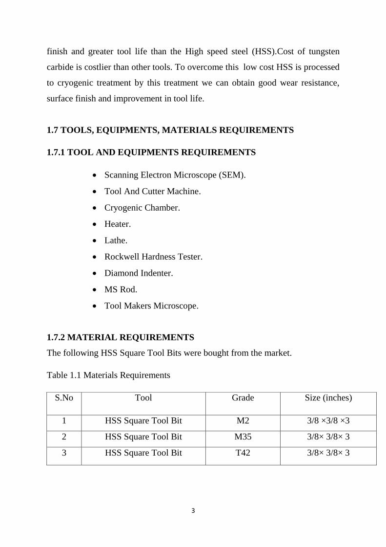
1.7.2 MATERIAL REQUIREMENTS
The following HSS Square Tool Bits were bought from the market.
Table 1.1 Materials Requirements
S.No Tool Grade Size (inches)
1 HSS Square Tool Bit M2 3/8 ×3/8 ×3
2 HSS Square Tool Bit M35 3/8× 3/8× 3
3 HSS Square Tool Bit T42 3/8× 3/8× 3
4
CHAPTER 2
LITERATURE REVIEW
In recent decades, there has been an increase in interest in the application
of cryogenic treatment to different materials. Research has shown that
cryogenic treatment increases product life, and in most cases, provides
additional qualities to the product, such as stress relieving. In the area of cutting
tools, extensive study has been done on tool steels, which include high-speed
steel (HSS) and medium carbon steels. It has been reported that cryogenic
treatment can double the service life of HSS tools, and also increase hardness
and toughness simultaneously.
Several different cryogenic processes have been tested by researchers.
These involve a combination of deep freezing and tempering cycles. Generally,
they can be described as a controlled lowering of temperature from room
temperature to the boiling point of liquid nitrogen (−196 °C), maintenance of
the temperature for about twenty four hours, followed by a controlled rising of
the temperature back to room temperature. Subsequent tempering processes
may follow Barron after cryogenically treating several materials including the
M2 high speed steel at −84 °C (maintaining it at this temperature for 24 hrs)
observed a significant improvement on the wear resistance in sliding abrasion
tests when compared to conventionally heat treated steel (quenched and
tempered)
When the temperature of the cryogenic treatment was reduced further to
−196°C, the wear resistance was increased even more. He has attributed the
improvement of the wear resistance of these tools to another mechanism besides
the transformation of the retained austenite into martensite. He verified that the
tool steels submitted to conventional heat treatment presented only a small
5
amount of retained austenite, but those submitted to cryogenic treatment
showed better performance during machining. This new mechanism would be
time and temperature dependent due to the long period (8 hrs or more) during
which the tools would have to stay at cryogenic temperatures. Before the
cryogenic treatment the microstructure showed relatively large carbides (20 μm)
dispersed in the matrix. After the cryogenic treatment, carbide particles as small
as 5 μm were found. The carbide refinement could in such a way contribute to
the improvement of the wear resistance of the tool. Barron thus attributed this
achievement both to austenite transformation and to the presence of hard and
small carbide particles well distributed among the larger carbide particles within
the martensite matrix
Donig at all did a detailed study on the effects of varying the deep
freezing and tempering cycles on high speed steel and confirmed that in tool
steels, this treatment affects the material in two ways. Firstly, it eliminates
retained austenite, and hence increases the hardness of the material. Secondly,
this treatment initiates nucleation sites for precipitation of large numbers of very
fine carbide particles, resulting in an increase in wear resistance
Paulin also verified the presence of fine precipitated carbide particles and
their importance to the material properties. The precipitated carbides reduce
internal tension of the martensite and minimize micro cracks susceptibility,
while the uniform distribution of fine carbides of high hardness enhances the
wear resistance. Huang et all confirmed that cryogenic treatment not only
facilitate the carbide formation but can also make the carbide distribution more
homogeneous.
Mohan Lal made a comparative study on wear resistance improvement of
cryogenically treated samples with standard heat-treated samples through flank
wear test and sliding wear test. Untemper samples when cryogenically treated
6
yield 3%, 10% and 10.6% extra life over tempered and cryogenically treated
T1, M2 and D3 samples, respectively. Hence it is suggested to cryogenically
treat without tempering. Tempered samples when cryogenically treated at 133 K
for 24 h yielded negative results, but when cryogenically treated at 93 K for 24
h the results were favorable. Hence tempered samples if treated at still lower
temperatures may yield still better results on par with untemper cryo treated
samples. This also suggested concluding that the stabilization of phases that
would take place during tempering requires sufficient degree of undercooling
and time to get transformed to stable harder/tougher phases that offer better
wear resistance. Cryogenic treatment done at 93 K as per the prescribed cycle
yields 20% extra life as compared to the maximum life achieved through cold
treatment. Cryogenic treatment at 93K for 24 hours is superior to Tin coatings
also. The effect of cryotreatment on Tin coating is not favorable which may be
because of uneven contraction of the coating material and the substrate leading
to incipient cracks at the interface. Hence cryo treatment should not follow Tin
coating.
The conventionally heat-treated and cryogenically treated specimens
showed the largest and smallest wear volume at all sliding distance,
respectively. From the microstructure of the steel it is reported that the
improvement in wear resistance after cryogenic treatment can be attributed to η-
carbide precipitates.
The wear resistances and tool life of M35 HSS tools significantly
improved under dry machining conditions of stainless steels due to
transformation of retained austenite to martensite.
The effects of cryogenic treatment on metallurgy of various tool steels
investigated by various researchers have been reported in detail. The
improvement in mechanical properties by cryogenic processing is attributed to
7
the combined Effects of the conversion of retained austenite to martensite and
participation of fine carbide.
DR.N. B. Dhokey The cryogenic treatment (below minus 150°C) is not
widely used in industry for tool steels although shallow sub-zero treatment (till
minus 80°C) is commonly practiced in the industry. Recent published research
indicated that the cryogenic treatment induces definite metallurgical changes
only below -150°C. Hence user of the tools can surely be benefitted by
practicing cryogenic treatment. It facilitates transformation of retained austenite
into the martensite, grain refinement and Nano sized formation of carbides in
the microstructure that results in the enhancement of the wear resistance to the
extent of 90% or more.
The conventionally treated T42 and M35 show higher carbide density
than M2. The peak carbide density and hardness with maximum reduction in
wear rate by 55 %, 90 % and 96 % at 8 h, 16 h, and 32 h for T42, M35, and M2
steels respectively that might be attributed to high rate of nucleation of carbides
and completely transformation of retained austenite to martensite.
8
CHAPTER 3
TOOL GEOMETRY AND SELECTION
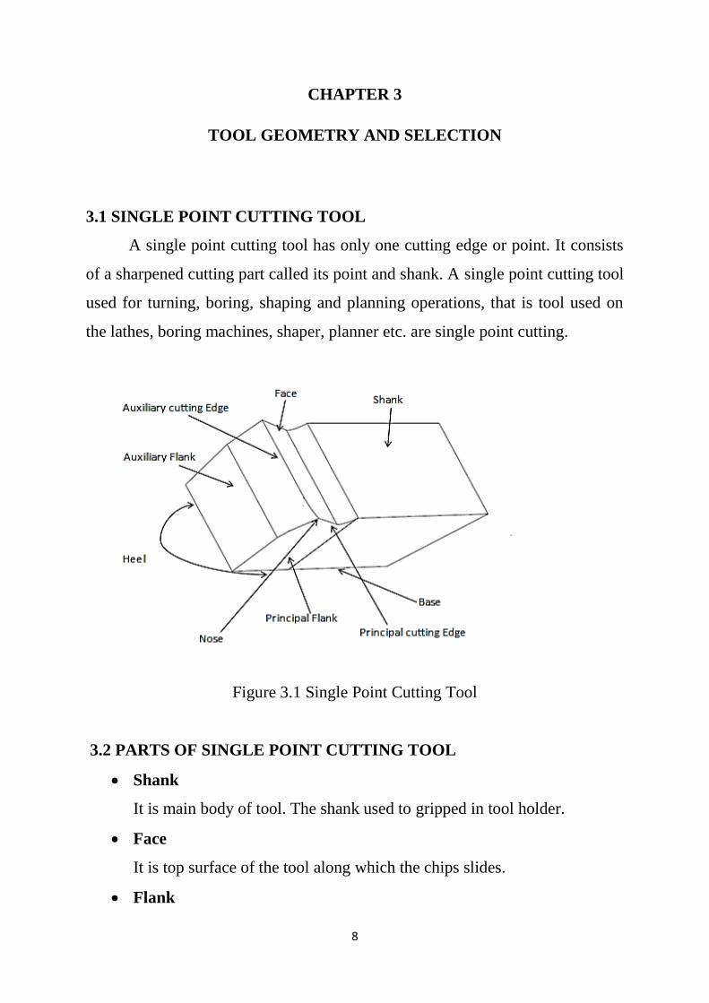
3.1 SINGLE POINT CUTTING TOOL
A single point cutting tool has only one cutting edge or point. It consists
of a sharpened cutting part called its point and shank. A single point cutting tool
used for turning, boring, shaping and planning operations, that is tool used on
the lathes, boring machines, shaper, planner etc. are single point cutting.
Figure 3.1 Single Point Cutting Tool
3.2 PARTS OF SINGLE POINT CUTTING TOOL
Shank
It is main body of tool. The shank used to gripped in tool holder.
Face
It is top surface of the tool along which the chips slides.
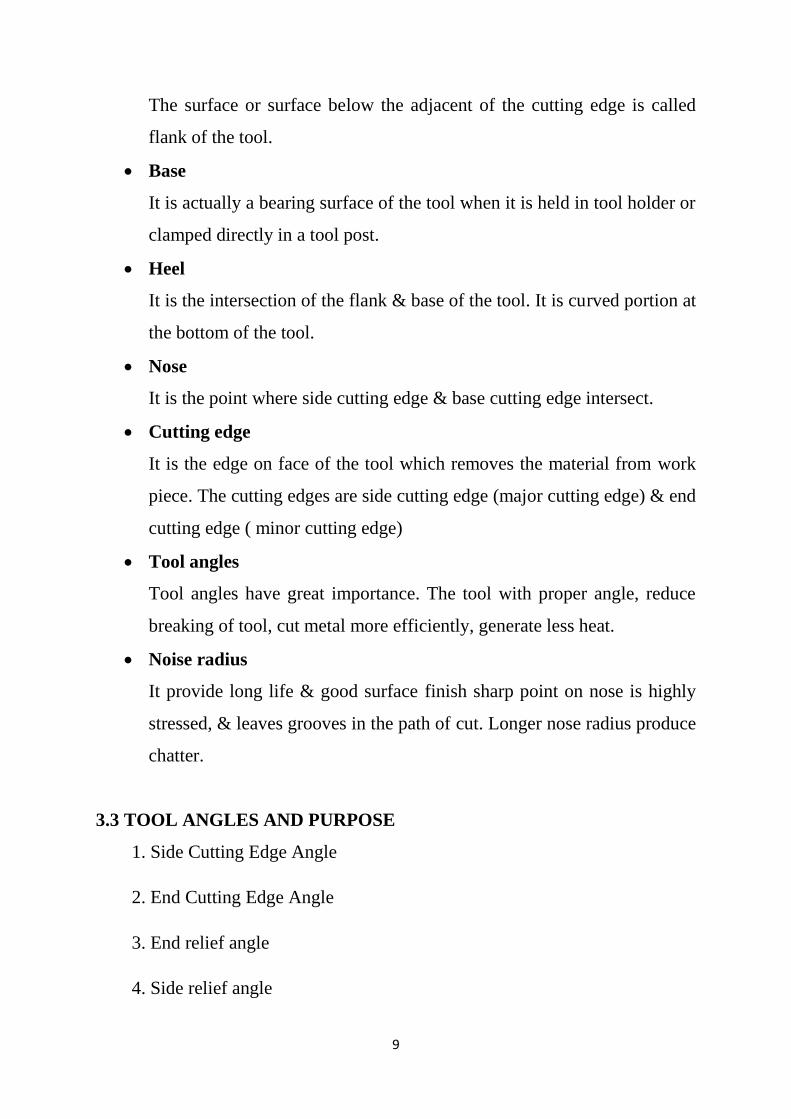
Flank
9
The surface or surface below the adjacent of the cutting edge is called
flank of the tool.
Base
It is actually a bearing surface of the tool when it is held in tool holder or
clamped directly in a tool post.
Heel
It is the intersection of the flank & base of the tool. It is curved portion at
the bottom of the tool.
Nose
It is the point where side cutting edge & base cutting edge intersect.
Cutting edge
It is the edge on face of the tool which removes the material from work
piece. The cutting edges are side cutting edge (major cutting edge) & end
cutting edge ( minor cutting edge)
Tool angles
Tool angles have great importance. The tool with proper angle, reduce
breaking of tool, cut metal more efficiently, generate less heat.
Noise radius
It provide long life & good surface finish sharp point on nose is highly
stressed, & leaves grooves in the path of cut. Longer nose radius produce
chatter.
3.3 TOOL ANGLES AND PURPOSE
1. Side Cutting Edge Angle
2. End Cutting Edge Angle
3. End relief angle
4. Side relief angle
10
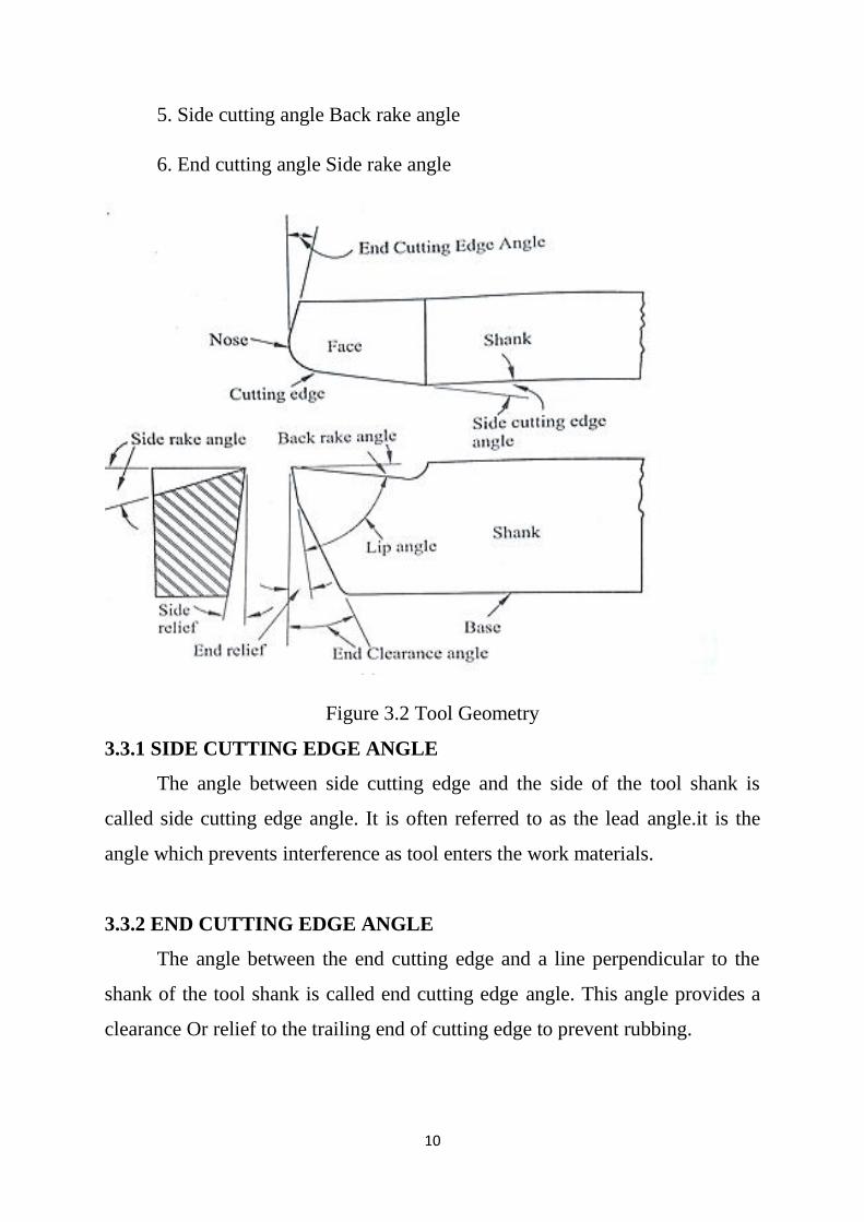
5. Side cutting angle Back rake angle
6. End cutting angle Side rake angle
Figure 3.2 Tool Geometry
3.3.1 SIDE CUTTING EDGE ANGLE
The angle between side cutting edge and the side of the tool shank is
called side cutting edge angle. It is often referred to as the lead angle.it is the
angle which prevents interference as tool enters the work materials.
3.3.2 END CUTTING EDGE ANGLE
The angle between the end cutting edge and a line perpendicular to the
shank of the tool shank is called end cutting edge angle. This angle provides a
clearance Or relief to the trailing end of cutting edge to prevent rubbing.

11
3.3.3 SIDE RELIEF ANGLE
The angle between the portion of the side flank immediately below the
side cutting edge and a line perpendicular to the base of the tool. Clearance
Angle is essentially provided to avoid rubbing of the tool (flank) with the
machined surface which causes loss of energy and damages of both the tool and
the job surface.
3.3.4 END RELIEF ANGLE
The angle between the end flank and the line perpendicular to the base of
the tool is called end relief angle.
3.3.5 BACK RAKE ANGLE
The angle between the face of the tool and line perpendicular to the base
of the tool measures on perpendicular plane through the side cutting edge. It is
the angle which measures the slope of the face of the tool from the nose,
towards the rack. If the slope is downward the nose it is negative back rake.
3.3.6 SIDE RAKE ANGLE
The angle between the face of the tool and a line parallel to the base of
the tool measured on plane perpendicular to the base and the side edge.
It is the angle that measures the slope of the tool face from the cutting edge, if
the slope is towards the cutting edge it is negative side rake angle and if the
slope is away from the cutting edge, it is positive side rake angle. If there is no
slope the side rake angle is zero.
Positive rake – helps reduce cutting force and thus cutting power requirement.
Negative rake – to increase edge-strength and life of the tool
Zero rake – to simplify design and manufacture of the form tools
12
CHAPTER 4
HIGH SPEED TOOL STEEL
4.1 INTRODUCTION
High-speed steel (HSS or HS) is a subset of tool steels, commonly used in
tool bits and cutting tools. It is often used in power-saw blades and drill bits. It
is superior to the older high-carbon steel tools used extensively in that it can
withstand higher temperatures without losing its temper. This property allows
HSS to cut faster than high carbon steel, hence the name high-speed steel. At
room temperature, in their generally recommended heat treatment, HSS grades
generally display high hardness and abrasion resistance (generally linked to
tungsten and vanadium content often used in HSS) compared with common
carbon and tool steels.
4.2 TYPES OF HSS
High speed steels are alloys that gain their properties from either tungsten
or molybdenum, often with a combination of the two. ASTM standards
recognize 7 tungsten types and 17 molybdenum types.
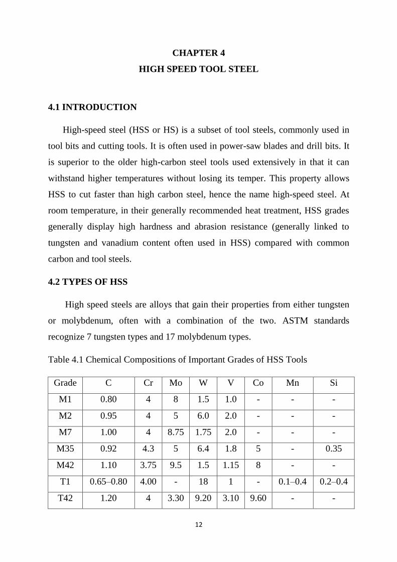
Table 4.1 Chemical Compositions of Important Grades of HSS Tools
Grade C Cr Mo W V Co Mn Si
M1 0.80 4 8 1.5 1.0 - - -
M2 0.95 4 5 6.0 2.0 - - -
M7 1.00 4 8.75 1.75 2.0 - - -
M35 0.92 4.3 5 6.4 1.8 5 - 0.35
M42 1.10 3.75 9.5 1.5 1.15 8 - -
T1 0.65–0.80 4.00 - 18 1 - 0.1–0.4 0.2–0.4
T42 1.20 4 3.30 9.20 3.10 9.60 - -
13
4.2.1 TUNGSTEN - BASE HIGH SPEED TOOL STEELS
4.2.1.1 T1 HSS TOOL
The original HSS, it has been generally superseded by M2.
4.2.2 MOLYBDENUM BASE HIGH SPEED TOOL STEELS
Adding molybdenum to tungsten steel creates several alloys commonly
called "HSS", measuring 63-65 Rockwell Hardness.
4.2.2.1 M1 HSS TOOL
M1 lacks some of the red-hardness properties of M2, but is less
susceptible to shock and will flex more.
4.2.2.2 M2 HSS TOOL
M2 is the "standard" and most widely used industrial HHS. It has small
and evenly distributed carbides giving high wear resistance. Recommended for
use on non-ferrous metals or mild steel or free cutting material.
4.2.2.3 M7 HSS TOOL
M7 is used for making heavier construction drills where flexibility and
extended drill life are equally important.
4.2.3 COBALT HIGH SPEED STEELS
The addition of cobalt increases heat resistance, and can give a Rockwell
Hardness up to 85.
14
4.2.3.1 M35 HSS TOOL
M35 is similar to M2, but with 5% cobalt added. M35 is also known as
Cobalt Steel, HSSE or HSS-E. It will cut faster and last longer than M2.
Recommended for heavy metal cutting work on difficult materials and an ideal
general purpose HSS tool bit for machine shops where high production rates are
required.
4.2.3.2 T42 HSS TOOL
T42 is a molybdenum-series high-speed steel alloy with additional 10%
cobalt. It is widely used in metal manufacturing industries because of its
superior red-hardness as compared to more conventional high-speed steels,
allowing for shorter cycle times in production environments due to higher
cutting speeds or from the increase in time between tool changes.
Recommended for cutting High Alloy Steel in annealed condition
4.3 APPLICATIONS OF HSS
The main use of high-speed steels continues to be in the manufacture of
various cutting tools: drills, taps, milling cutters, tool bits, gear cutters, saw
blades, planer and jointer blades, router bits, etc., although usage for punches
and dies is increasing.
High speed steels also found a market in fine hand tools where their
relatively good toughness at high hardness, coupled with high abrasion
resistance, made them suitable for low speed applications requiring a durable
keen (sharp) edge, such as files, chisels, hand plane blades, and high quality
kitchen, pocket knives, and swords.

15
High speed steel tools are the most popular for use in woodturning, as the
speed of movement of the work past the edge is relatively high for handheld
tools, and HSS holds its edge far longer than high carbon steel tools can.
4.4 SELECTION OF TOOLS
We selected three grades of tools. They are M2 HSS TOOL, M35 HSS
TOOL, T42 HSS TOOL.M2 HSS TOOL is one of the best tool used in small
scale industry. M35 HSS TOOL has 5% cobalt content .It is harder than M2
grade. It is used for smooth machinging.T42 HSS TOOL has 10% cobalt
content. It is used for rough machining. It is harder than M2 &M35.
16
CHAPTER 5
CRYOGENIC TREATMENT
5.1 INTRODUCTION
A cryogenic treatment is the process of treating work pieces to cryogenic
temperatures (i.e. below −190 °C (−310 °F)) in order to remove residual stresses
and improve wear resistance on steels. In addition to seeking enhanced stress
relief and stabilization, or wear resistance, cryogenic treatment is also sought
for its ability to improve corrosion resistance by precipitating micro-fine eta
carbides. Cryogenic hardening is a cryogenic treatment process where the
material is cooled to very low temperatures. By using liquid nitrogen, the
temperature can go as low as −190 °C. It can have a profound effect on the
mechanical properties of certain materials, such as steels or tungsten carbide.
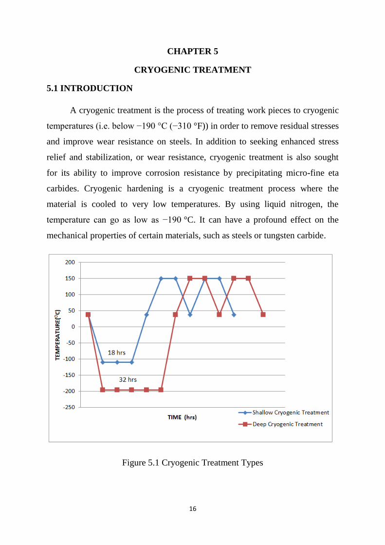
Figure 5.1 Cryogenic Treatment Types
17
5.2 TYPES OF CRYOGENIC TREATMENT
There are two types of Cryogenic Treatment. They are
1. Shallow Cryogenic Treatment
2. Deep Cryogenic Treatment
5.2.1 SHALLOW CRYOGENIC TREATMENT
Shallow Cryogenic process involves cooling down samples to –110°C
with soaking period of 18 hrs. Then brought back to room temperature by
heating, followed by two tempering cycles consisting of heating to 150°C then
bring back to room temperature.
5.2.2 DEEP CRYOGENIC TREATMENT
Deep Cryogenic process involves cooling down samples to –196°C with
soaking period of 32 hrs then brought back to room temperature by heating,
followed by two tempering cycles consisting of heating to 150°C then bring
back to room temperature.
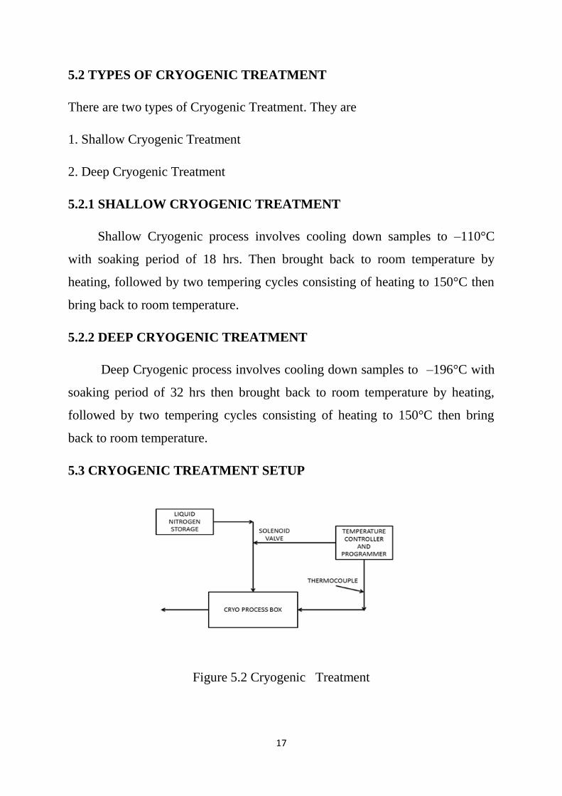
5.3 CRYOGENIC TREATMENT SETUP
Figure 5.2 Cryogenic Treatment
18
The heat-exchanger system passes liquid nitrogen through a heat
exchanger, and the exhaust gas from the unit is piped into the main gaseous-
nitrogen header line. The chamber atmosphere is drawn over the heat-exchanger
coils by a fan. In some versions of the system, the cooling is boosted by
spraying liquid nitrogen directly into the chamber.
The direct spray system sprays liquid nitrogen directly into the chamber,
while a fan circulates the gases over the work. In this system, the spent gas
cannot be recovered for use as a furnace atmosphere. The equipment design
does not permit the liquid nitrogen to come into direct contact with the work,
thereby reducing the probability of thermal shock
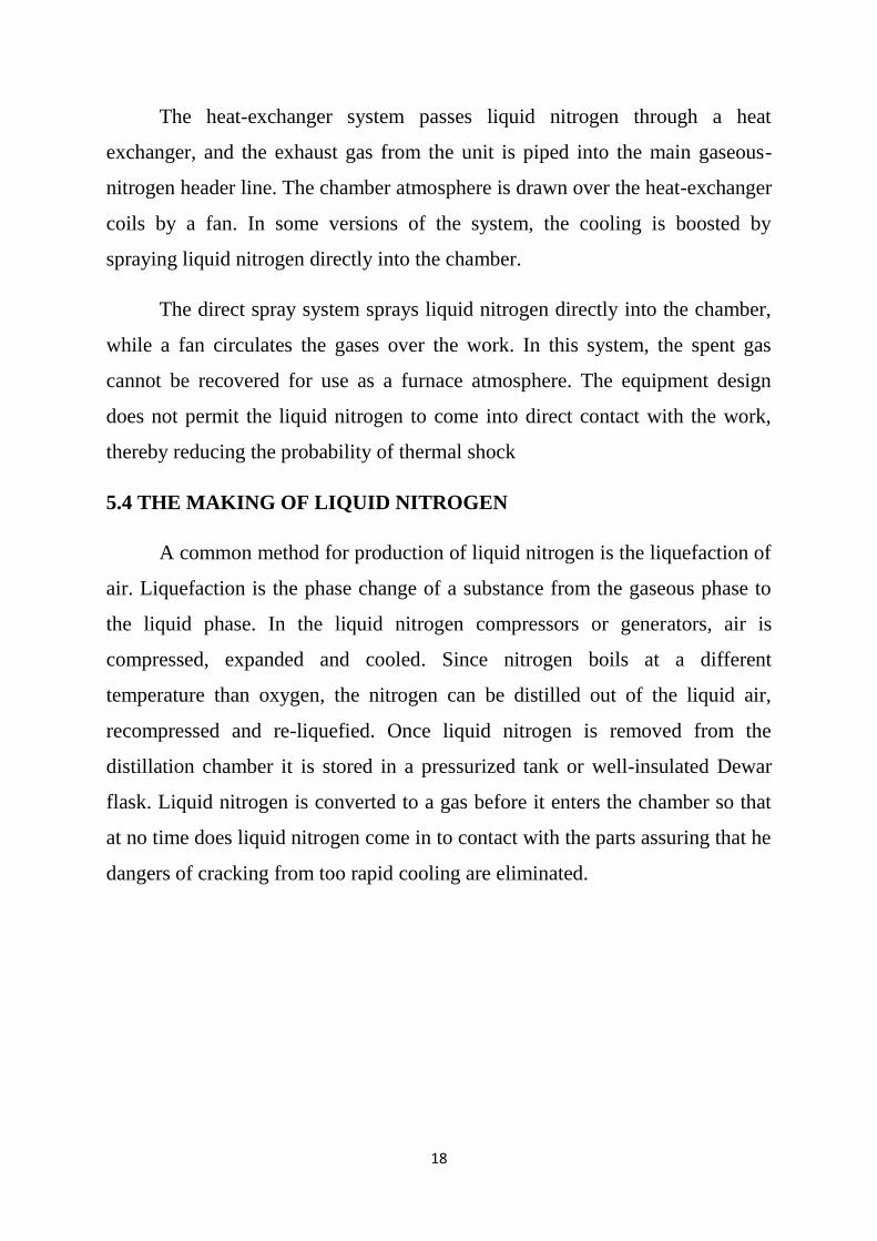
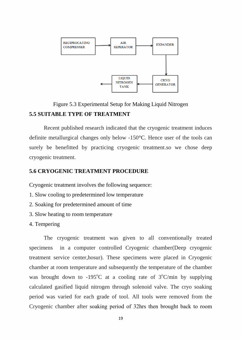
5.4 THE MAKING OF LIQUID NITROGEN
A common method for production of liquid nitrogen is the liquefaction of
air. Liquefaction is the phase change of a substance from the gaseous phase to
the liquid phase. In the liquid nitrogen compressors or generators, air is
compressed, expanded and cooled. Since nitrogen boils at a different
temperature than oxygen, the nitrogen can be distilled out of the liquid air,
recompressed and re-liquefied. Once liquid nitrogen is removed from the
distillation chamber it is stored in a pressurized tank or well-insulated Dewar
flask. Liquid nitrogen is converted to a gas before it enters the chamber so that
at no time does liquid nitrogen come in to contact with the parts assuring that he
dangers of cracking from too rapid cooling are eliminated.
19
Figure 5.3 Experimental Setup for Making Liquid Nitrogen
5.5 SUITABLE TYPE OF TREATMENT
Recent published research indicated that the cryogenic treatment induces
definite metallurgical changes only below -150°C. Hence user of the tools can
surely be benefitted by practicing cryogenic treatment.so we chose deep
cryogenic treatment.
5.6 CRYOGENIC TREATMENT PROCEDURE
Cryogenic treatment involves the following sequence:
1. Slow cooling to predetermined low temperature
2. Soaking for predetermined amount of time
3. Slow heating to room temperature
4. Tempering
The cryogenic treatment was given to all conventionally treated
specimens in a computer controlled Cryogenic chamber(Deep cryogenic
treatment service center,hosur). These specimens were placed in Cryogenic
chamber at room temperature and subsequently the temperature of the chamber
was brought down to -195oC at a cooling rate of 3
oC/min by supplying
calculated gasified liquid nitrogen through solenoid valve. The cryo soaking
period was varied for each grade of tool. All tools were removed from the
Cryogenic chamber after soaking period of 32hrs then brought back to room

20
temperature then brought back to room temperature by heating, followed by two
tempering cycles consisting of heating to 150°C then bring back to room
temperature.
5.7 IMPORTANCE OF CRYOGENIC TREATMENT
Cryogenic processing with materials at the molecular level at Cryogenic
treatment resulting in
Homogenizes the crystal structure: Achieved by specially designed
advanced ramp-soak time programs.
Grain structure refinement: New ultra-fine carbide particles are formed
which are uniformly dispersed throughout the material matrix.
Prevent concentrated heat built up: Tools, Carbide tools, ball and roller
bearings and tools, turbine blades, combustion, chamber, steel industry
automobile industry etc. significantly benefit from this improvement.
Regained austenite is converted to a fine martensite matrix: Significant
improvement in dimensional stability.
Relieves residual stresses.
Significant improvement in material toughness.
21
CHAPTER 6
METHODOLOGY
6.1 EXPERIMENTAL STEPS
The commercially available three grades of HSS tool blank were bought
from market.
Required tool signatures were obtained from by help of Tool and Cutter
machine and Tool Maker‟s Microscope.
Then microstructures of tools were obtained using scanning electron
microscope.
Then the three grades of tool were selected (one tool from each grade).
They were Cryogenic Treated.
After the treatment changed microstructure was obtained using SEM.
Then the hardness of all the tools were measured by using Rockwell
Hardness Tester.
Turning operation of work piece was performed in centre lathe by using
treated and untreated tools.
Flank wear was measured by using toolmakers microscope in certain
intervals of machining time.
Readings were tabulated and Graphs were drawn.

22
6.2 FLOW CHART
Figure 6.1 FLOW CHART

23
CHAPTER 7
MACHINING OPERATION AND MEARSUREMENTS
7.1 CENTRE LATHE
A lathe is a machine tool that rotates the work piece on its axis to
perform various operations such as cutting, sanding, knurling, drilling, or
deformation, facing, turning, with tools that are applied to the work piece to
create an object with symmetry about an axis of rotation.
7.2 TURNING
Turning is a machining operation for all types of metallic and non-
metallic materials and is capable of producing circular parts with straight or
various profiles. The cutting tools may be single-point or form tools. The most
common machine tool used is a lathe; modern lathes are computer-controlled
and can achieve high production rates with little labour. The basic operation is
shown in Fig. 7.1, where the work piece is held in a chuck and rotates at N
r/min; a cutting tool moves along the length of the piece at a feed f (in/r or
mm/r) and removes material at a radial depth d, reducing the diameter from D1
to D2.
Figure 7.1 Turning
24
7.3 SUITABLE OPERATION
In recent years ,much research has dealt with effect of cryogenic
treatment on cutting tools in turning operations.it is understood that the
cryogenic treatment of inserts provides many positive effects in turning
including reduction of cutting force and surface roughness along with greater
wear resistance and tool life. So our experimental work mainly focused on
turning operation.
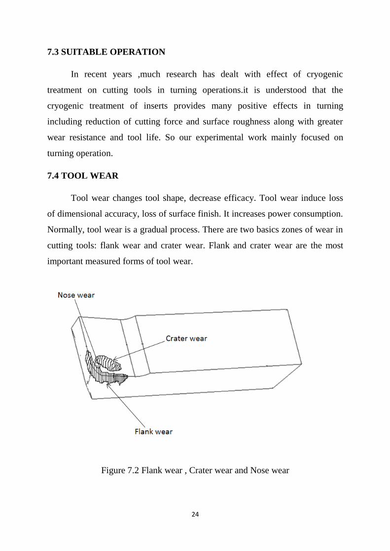
7.4 TOOL WEAR
Tool wear changes tool shape, decrease efficacy. Tool wear induce loss
of dimensional accuracy, loss of surface finish. It increases power consumption.
Normally, tool wear is a gradual process. There are two basics zones of wear in
cutting tools: flank wear and crater wear. Flank and crater wear are the most
important measured forms of tool wear.
Figure 7.2 Flank wear , Crater wear and Nose wear

25
7.5 VARIOUS TYPES OF WEAR
7.5.1 FLANK WEAR
Flank wear in which the portion of the tool in contact with the finished
part erodes. The amount of flank wear is often used as a criterion because it is
the flank wear that influences work material surface roughness and accuracy.
7.5.2 CRATER WEAR
Crater wear in which contact with chips erodes the rake face. This is
somewhat normal for tool wear, and does not seriously degrade the use of a tool
until it becomes serious enough to cause a cutting edge failure.
7.5.3 NOSE WEAR
It occurs on the tool corner. It can be considered as a part of the wear
land and respectively flank wear since there is no distinguished boundary
between the corner wear and flank wear land. We consider corner wear as a
separate wear type because of its importance for the precision of machining.
Corner wear actually shortens the cutting tool thus increasing gradually the
dimension of machined surface and introducing a significant dimensional error
in machining,
7.6 WEAR MEASUREMENT
The various methods are,
By loss of tool material in volume or weight, in one life time – this
method is crude and is generally applicable for critical tools like grinding
wheels.
by grooving and indentation method – in this approximate method wear
depth is measured indirectly by the difference in length of the groove or
the indentation outside and inside the worn area
26
using optical microscope fitted with micrometer – very common and
effective method
using scanning electron microscope (SEM) – used generally, for detailed
study; both qualitative and quantitative
Talysurf, specially for shallow crater wear.
In our project we have chosen Tool Maker‟s Microscope for measuring flank
wear.
7.7 TOOL MAKERS MICROSCOPE
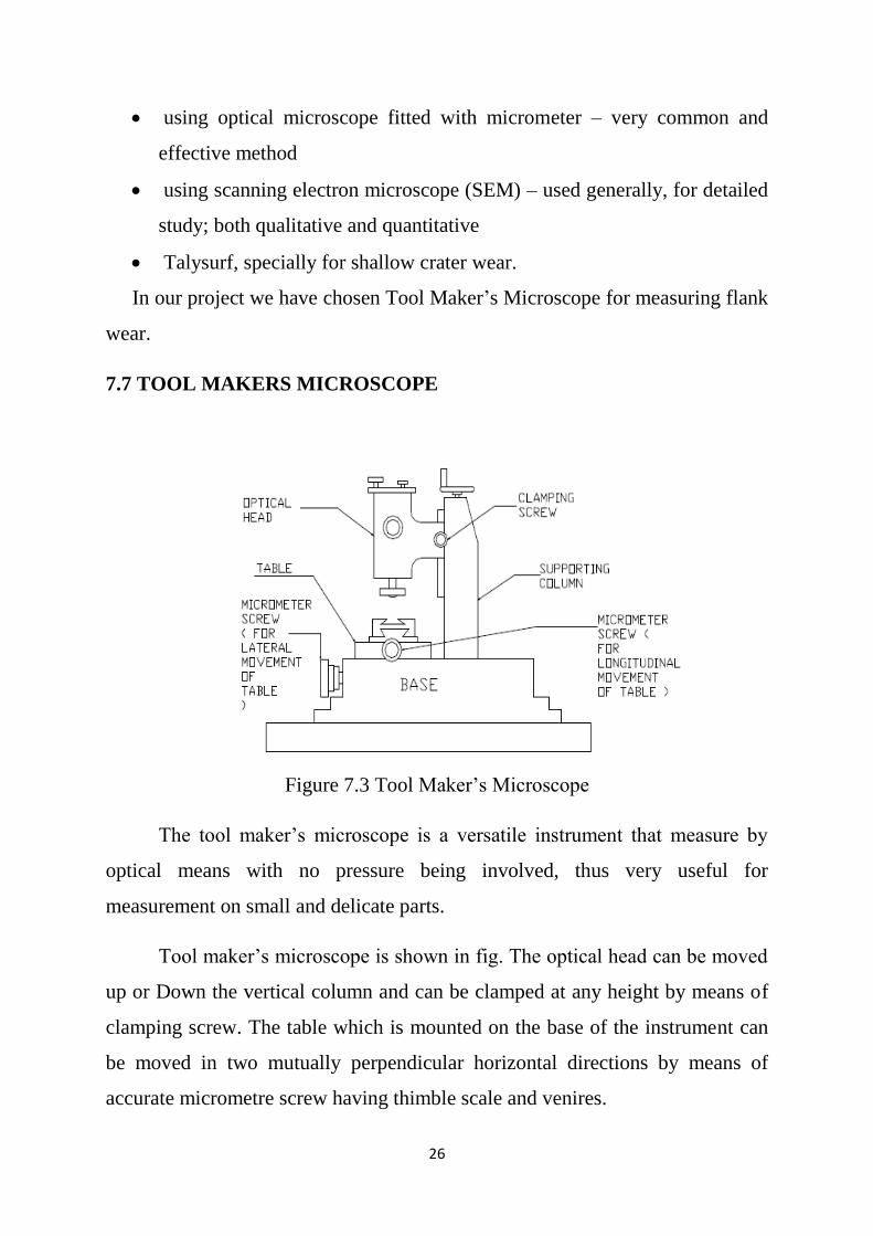
Figure 7.3 Tool Maker‟s Microscope
The tool maker‟s microscope is a versatile instrument that measure by
optical means with no pressure being involved, thus very useful for
measurement on small and delicate parts.
Tool maker‟s microscope is shown in fig. The optical head can be moved
up or Down the vertical column and can be clamped at any height by means of
clamping screw. The table which is mounted on the base of the instrument can
be moved in two mutually perpendicular horizontal directions by means of
accurate micrometre screw having thimble scale and venires.

27
7.7.1 WEAR MEASUREMENT BY TOOL MAKERS MICROSCOPE
Fix the tool as specified in the following picture. Tool side which makes
back rake angle which makes slightly arc shape. Adjust the work table by
rotating to touch that arc end with the vertical line. And note the reading in the
working table & micro meter readings. Do the machining process.by that tool
flank radius reduced to some mm. To measure that fix the arc end with the
vertical line and make the tool edge parallel or merge with the horizontal line.
By screwing the micro meter to some mm, so that the difference between
current and before machining is the flank wear.
7.8 ROCKWELL HARDNESS TESTER
Rockwell hardness testing is a general method for measuring the bulk
hardness of metallic and polymer materials. Hardness testing is widely used for
material evaluation due to its simplicity and low cost relative to direct
measurement of many properties. This method consists of indenting the test
material with a diamond cone or hardened steel ball indenter. The indenter is
forced into the test material under a preliminary minor load F0 usually 10 kgf.
When equilibrium has been reached, an indicating device, which follows the
movements of the indenter and so responds to changes in depth of penetration
of the indenter, is set to a datum position. While the preliminary minor load is
still applied an additional major load is applied with resulting increase in
penetration.
Figure 7.4 Rockwell Hardness Tester
28
When equilibrium has again been reach, the additional major load is
removed but the preliminary minor load is still maintained. Removal of the
additional major load allows a partial recovery, so reducing the depth of
penetration. The permanent increase in depth of penetration, resulting from the
application and removal of the additional major load is used to calculate the
Rockwell hardness number.
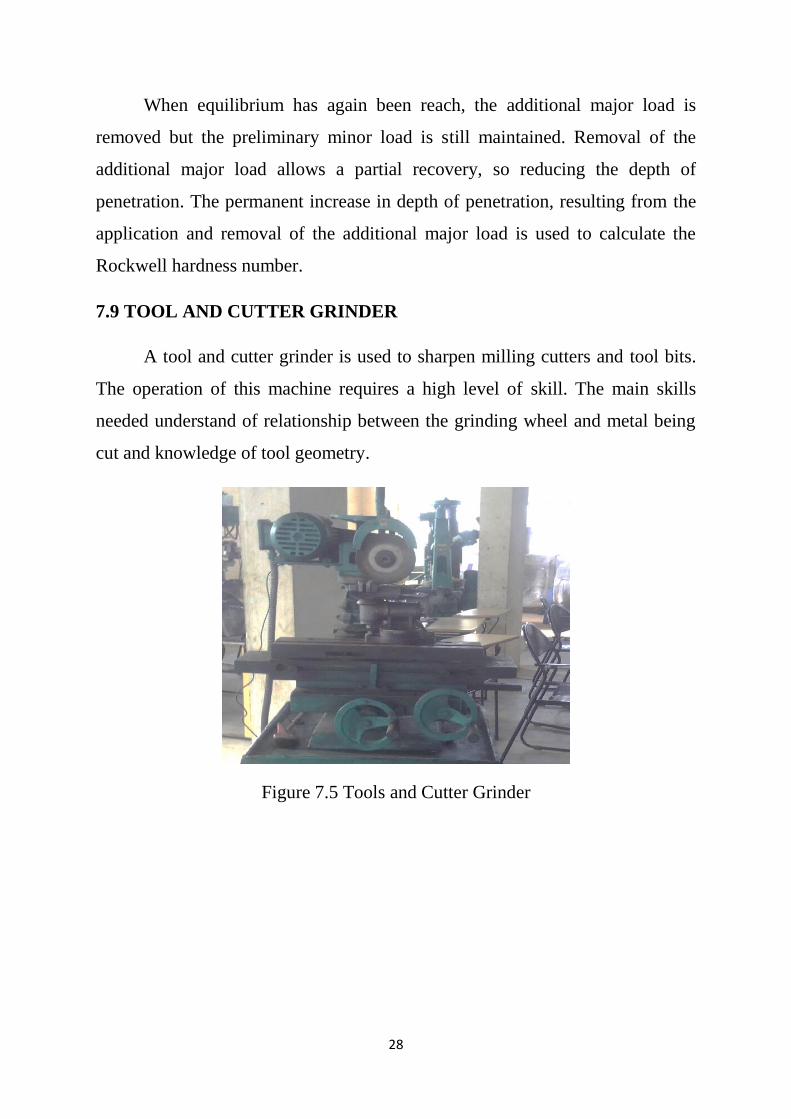
7.9 TOOL AND CUTTER GRINDER
A tool and cutter grinder is used to sharpen milling cutters and tool bits.
The operation of this machine requires a high level of skill. The main skills
needed understand of relationship between the grinding wheel and metal being
cut and knowledge of tool geometry.
Figure 7.5 Tools and Cutter Grinder
29
CHAPTER 8
SEM ANALYSIS
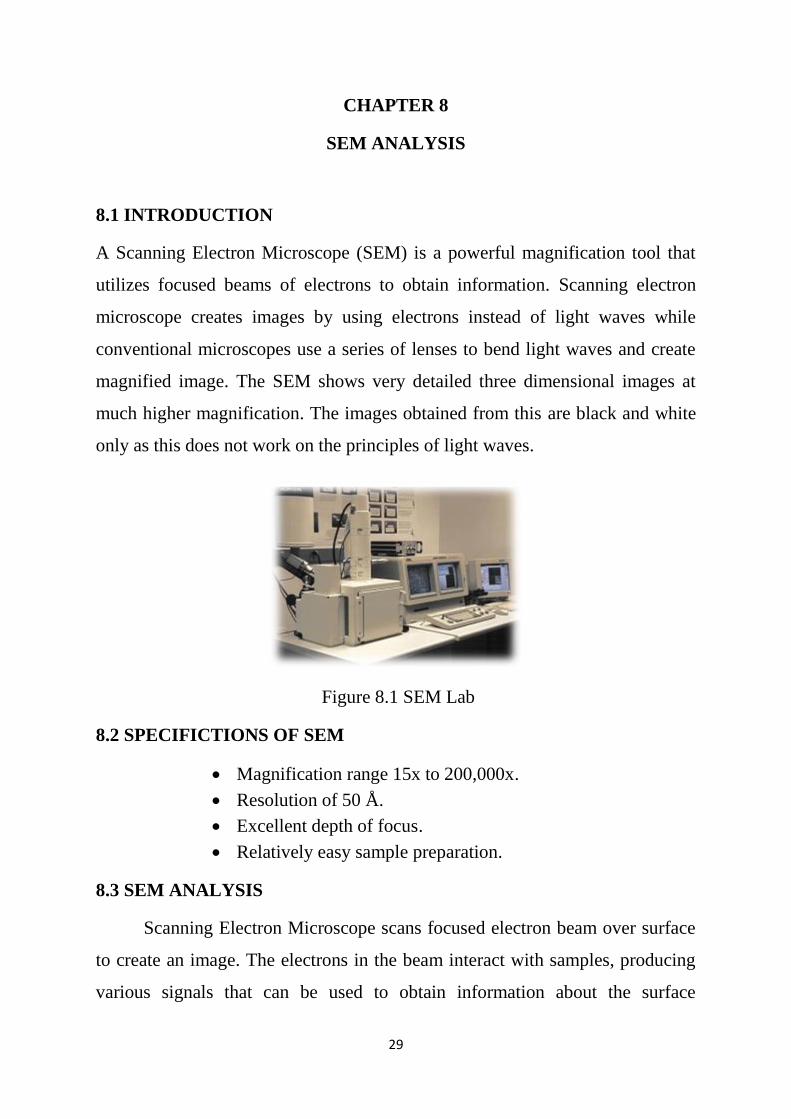
8.1 INTRODUCTION
A Scanning Electron Microscope (SEM) is a powerful magnification tool that
utilizes focused beams of electrons to obtain information. Scanning electron
microscope creates images by using electrons instead of light waves while
conventional microscopes use a series of lenses to bend light waves and create
magnified image. The SEM shows very detailed three dimensional images at
much higher magnification. The images obtained from this are black and white
only as this does not work on the principles of light waves.
Figure 8.1 SEM Lab
8.2 SPECIFICTIONS OF SEM
Magnification range 15x to 200,000x.
Resolution of 50 Å.
Excellent depth of focus.
Relatively easy sample preparation.
8.3 SEM ANALYSIS
Scanning Electron Microscope scans focused electron beam over surface
to create an image. The electrons in the beam interact with samples, producing
various signals that can be used to obtain information about the surface

30
topography and composition. SEM was carried for both cryogenic treated and
untreated HSS tools (various grades) to study the microstructural changes.
Results of the SEM analysis are shown in the table10.1 .The results showed
presence of the fine precipitated carbide particles in the case of cryogenically
treated samples which verify that the refinement of carbides takes place after the
cryogenic treatment for all grades of tools.
31
CHAPTER 9
EXPERIMENTATION
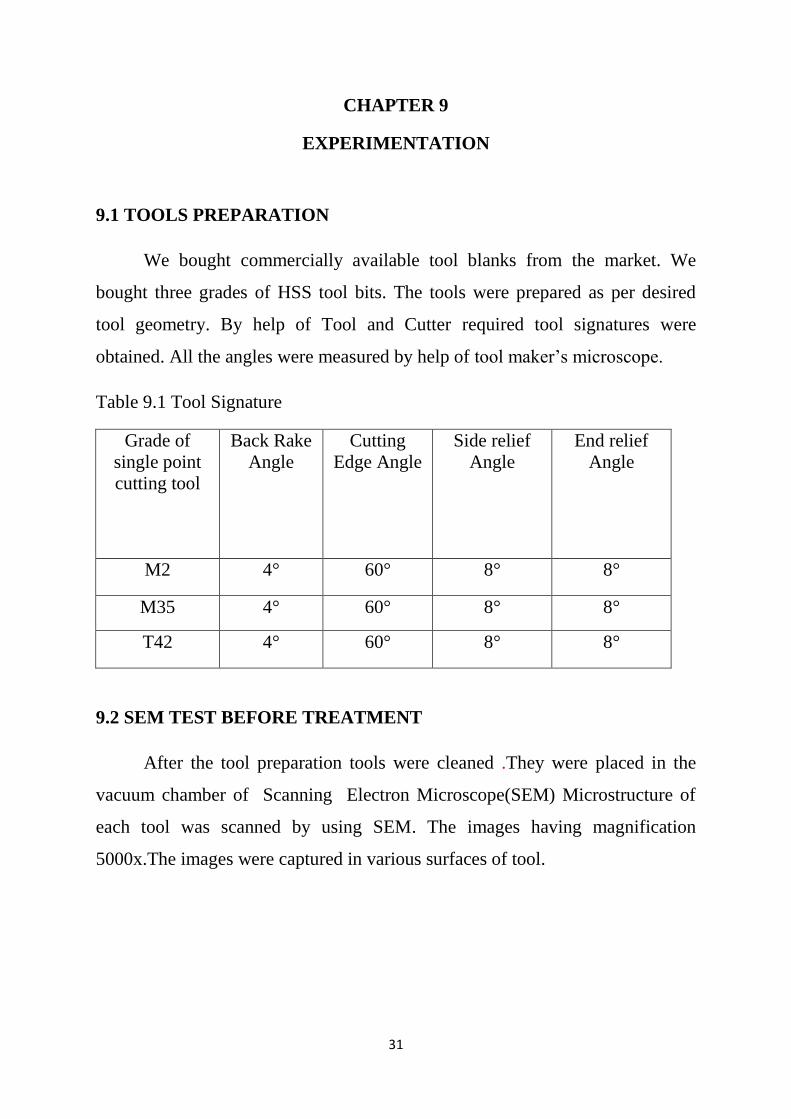
9.1 TOOLS PREPARATION
We bought commercially available tool blanks from the market. We
bought three grades of HSS tool bits. The tools were prepared as per desired
tool geometry. By help of Tool and Cutter required tool signatures were
obtained. All the angles were measured by help of tool maker‟s microscope.
Table 9.1 Tool Signature
Grade of
single point
cutting tool
Back Rake
Angle
Cutting
Edge Angle
Side relief
Angle
End relief
Angle
M2 4° 60° 8° 8°
M35 4° 60° 8° 8°
T42 4° 60° 8° 8°
9.2 SEM TEST BEFORE TREATMENT
After the tool preparation tools were cleaned .They were placed in the
vacuum chamber of Scanning Electron Microscope(SEM) Microstructure of
each tool was scanned by using SEM. The images having magnification
5000x.The images were captured in various surfaces of tool.
32
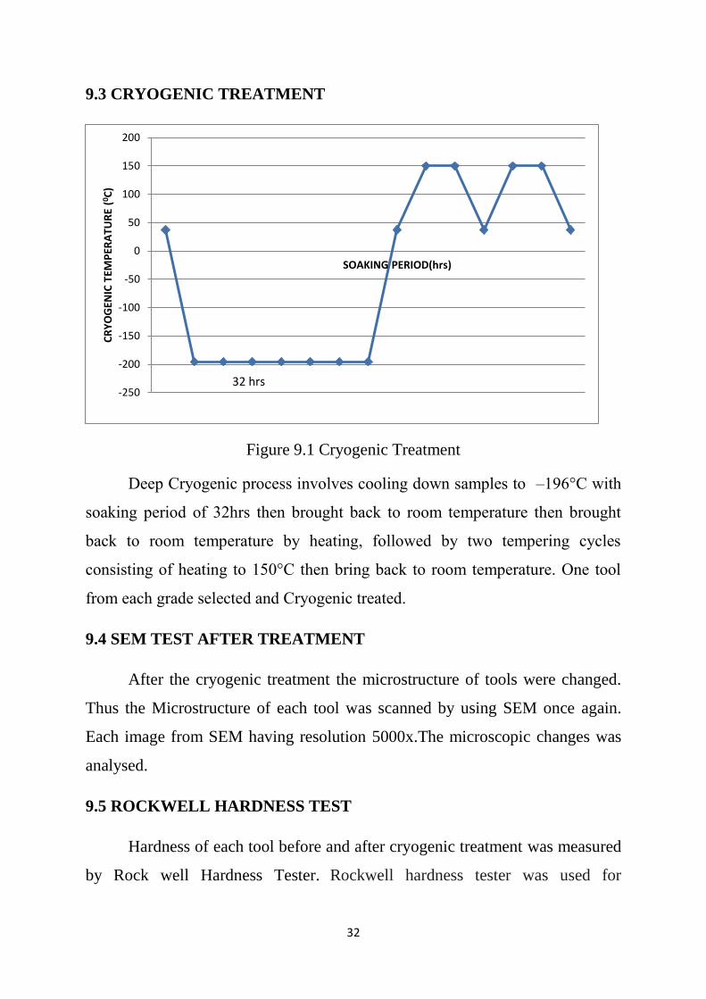
9.3 CRYOGENIC TREATMENT
Figure 9.1 Cryogenic Treatment
Deep Cryogenic process involves cooling down samples to –196°C with
soaking period of 32hrs then brought back to room temperature then brought
back to room temperature by heating, followed by two tempering cycles
consisting of heating to 150°C then bring back to room temperature. One tool
from each grade selected and Cryogenic treated.
9.4 SEM TEST AFTER TREATMENT
After the cryogenic treatment the microstructure of tools were changed.
Thus the Microstructure of each tool was scanned by using SEM once again.
Each image from SEM having resolution 5000x.The microscopic changes was
analysed.
9.5 ROCKWELL HARDNESS TEST
Hardness of each tool before and after cryogenic treatment was measured
by Rock well Hardness Tester. Rockwell hardness tester was used for
-250
-200
-150
-100
-50
0
50
100
150
200
CR
YO
GEN
IC T
EMP
ERA
TUR
E (0 C
)
SOAKING PERIOD(hrs)
32 hrs
33
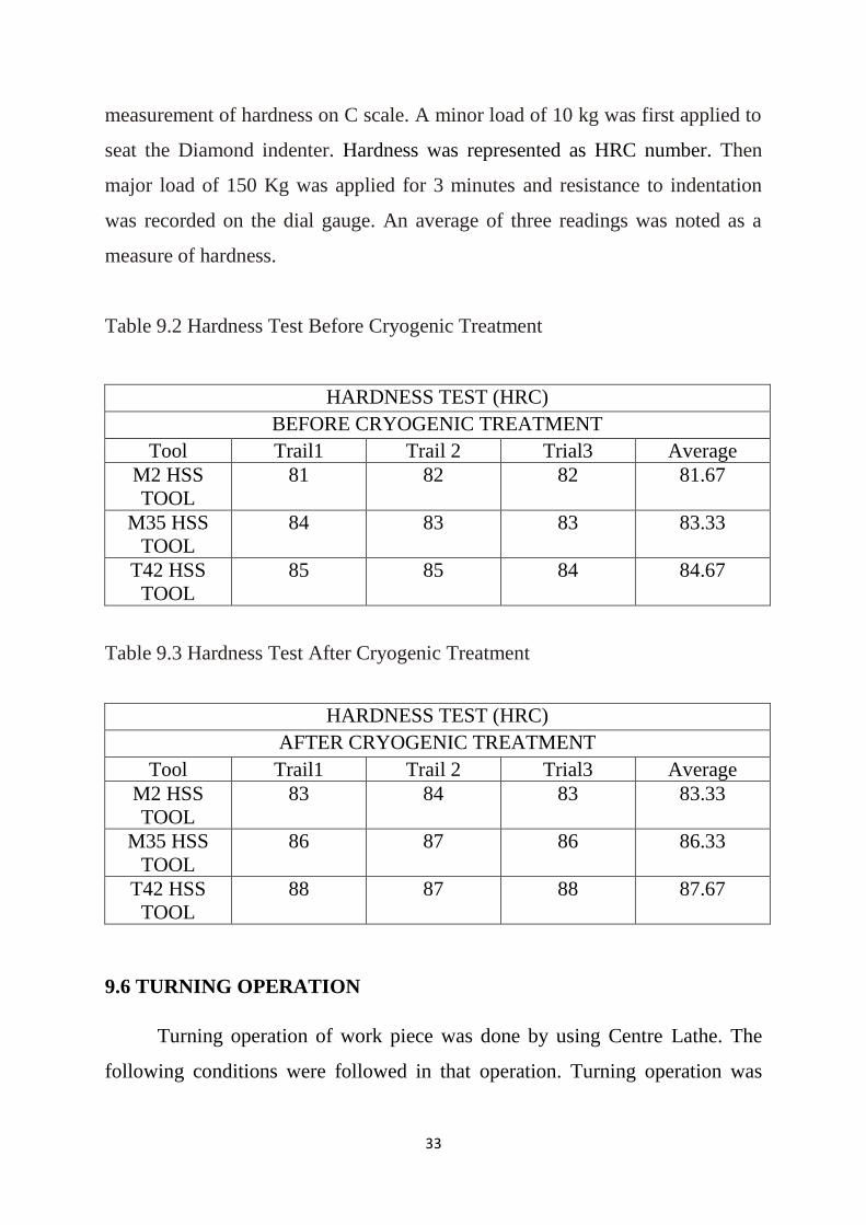
measurement of hardness on C scale. A minor load of 10 kg was first applied to
seat the Diamond indenter. Hardness was represented as HRC number. Then
major load of 150 Kg was applied for 3 minutes and resistance to indentation
was recorded on the dial gauge. An average of three readings was noted as a
measure of hardness.
Table 9.2 Hardness Test Before Cryogenic Treatment
HARDNESS TEST (HRC)
BEFORE CRYOGENIC TREATMENT
Tool Trail1 Trail 2 Trial3 Average
M2 HSS
TOOL
81 82 82 81.67
M35 HSS
TOOL
84 83 83 83.33
T42 HSS
TOOL
85 85 84 84.67
Table 9.3 Hardness Test After Cryogenic Treatment
HARDNESS TEST (HRC)
AFTER CRYOGENIC TREATMENT
Tool Trail1 Trail 2 Trial3 Average
M2 HSS
TOOL
83 84 83 83.33
M35 HSS
TOOL
86 87 86 86.33
T42 HSS
TOOL
88 87 88 87.67
9.6 TURNING OPERATION
Turning operation of work piece was done by using Centre Lathe. The
following conditions were followed in that operation. Turning operation was

34
performed by using various selected tools of treated and untreated. Turning
operation was performed for certain length up to maximum flank wear reached.
Table 9.4 Cutting Conditions
9.7 WEAR TEST
Flank wear of tool was measured by using Toolmakers Microscope. After
the certain period (machining time) of machining wear was measured. Flank
wear for the each grade of both treated and untreated tools were measured.
Table 9.5 Wear Test for Untreated M2 HSS Tool
S.No Length
(mm)
Machining Time
(min)
Flank Wear
(mm)
1 500 4.22 0.34
2 1000 8.44 0.61
Table 9.6 Wear Test for Cryogenic Treated M2 HSS Tool
S.No Length
(mm)
Machining Time
(min)
Flank Wear
(mm)
1 500 4.22 0.16
2 1000 8.44 0.32
3 1500 12.66 0.56
4 1750 14.77 0.63
Spindle speed 237 rpm
Depth of Cut 0.75 mm
Feed 0.5 mm/rev
Work piece M.S rod
35
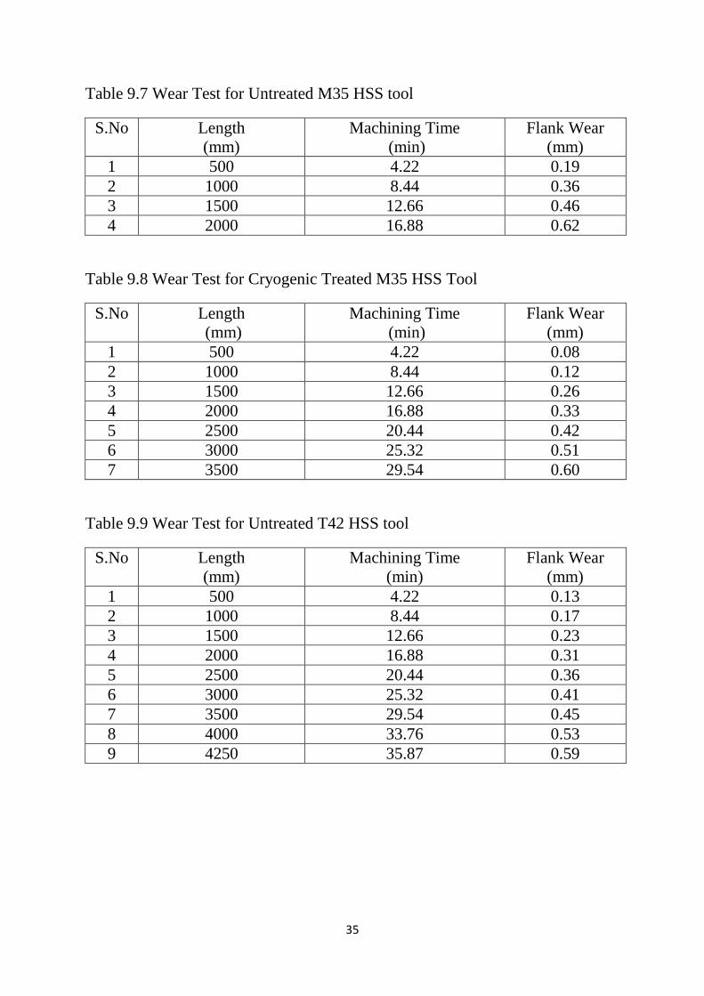
Table 9.7 Wear Test for Untreated M35 HSS tool
S.No Length
(mm)
Machining Time
(min)
Flank Wear
(mm)
1 500 4.22 0.19
2 1000 8.44 0.36
3 1500 12.66 0.46
4 2000 16.88 0.62
Table 9.8 Wear Test for Cryogenic Treated M35 HSS Tool
S.No Length
(mm)
Machining Time
(min)
Flank Wear
(mm)
1 500 4.22 0.08
2 1000 8.44 0.12
3 1500 12.66 0.26
4 2000 16.88 0.33
5 2500 20.44 0.42
6 3000 25.32 0.51
7 3500 29.54 0.60
Table 9.9 Wear Test for Untreated T42 HSS tool
S.No Length
(mm)
Machining Time
(min)
Flank Wear
(mm)
1 500 4.22 0.13
2 1000 8.44 0.17
3 1500 12.66 0.23
4 2000 16.88 0.31
5 2500 20.44 0.36
6 3000 25.32 0.41
7 3500 29.54 0.45
8 4000 33.76 0.53
9 4250 35.87 0.59

36
Table 9.10 Wear Test for Cryogenic Treated T42 HSS Tool
S.No Length
(mm)
Machining Time (min) Flank Wear
(mm)
1 500 4.22 0.06
2 1000 8.44 0.11
3 1500 12.66 0.15
4 2000 16.88 0.21
5 2500 20.44 0.26
6 3000 25.32 0.31
7 3500 29.54 0.37
8 4000 33.76 0.42
9 4500 37.98 0.46
10 5000 42.20 0.52
11 5500 46.20 0.55
12 6000 50.64 0.61
9.8 MACHINING TIME CALCULATION
Machining time,
t =
Where
L = length of the shaft (mm)
f = feed rate (mm/rev)
N=spindle speed (rpm)
PAREMETRES
L = 500 mm f = 0.5 mm/rev N= 237 rpm
t =
t =500/(0.5*237 ) =4.22 min
37
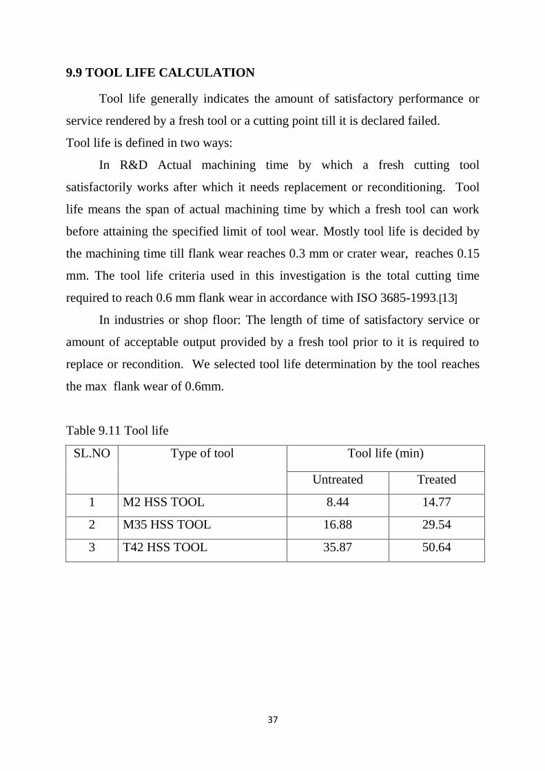
9.9 TOOL LIFE CALCULATION
Tool life generally indicates the amount of satisfactory performance or
service rendered by a fresh tool or a cutting point till it is declared failed.
Tool life is defined in two ways:
In R&D Actual machining time by which a fresh cutting tool
satisfactorily works after which it needs replacement or reconditioning. Tool
life means the span of actual machining time by which a fresh tool can work
before attaining the specified limit of tool wear. Mostly tool life is decided by
the machining time till flank wear reaches 0.3 mm or crater wear, reaches 0.15
mm. The tool life criteria used in this investigation is the total cutting time
required to reach 0.6 mm flank wear in accordance with ISO 3685-1993.[13]
In industries or shop floor: The length of time of satisfactory service or
amount of acceptable output provided by a fresh tool prior to it is required to
replace or recondition. We selected tool life determination by the tool reaches
the max flank wear of 0.6mm.
Table 9.11 Tool life
SL.NO Type of tool Tool life (min)
Untreated Treated
1 M2 HSS TOOL 8.44 14.77
2 M35 HSS TOOL 16.88 29.54
3 T42 HSS TOOL 35.87 50.64
38
CHAPTER 10
RESULT AND DISCUSSION
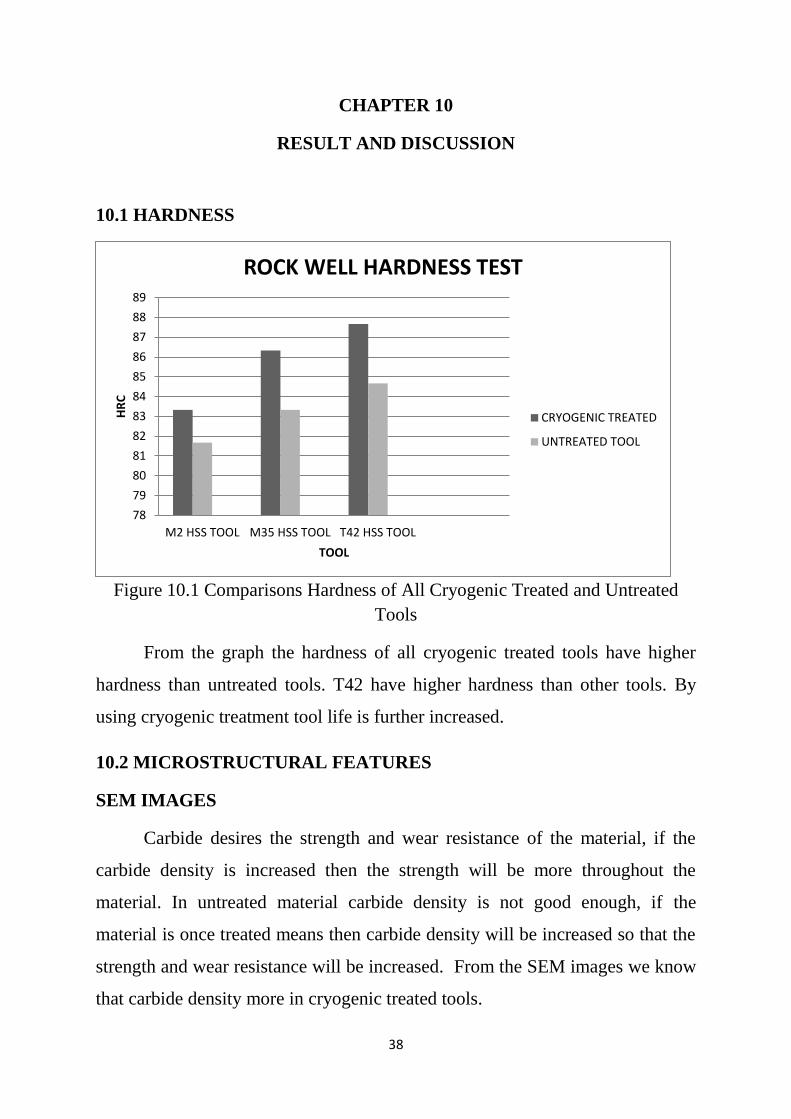
10.1 HARDNESS
Figure 10.1 Comparisons Hardness of All Cryogenic Treated and Untreated
Tools
From the graph the hardness of all cryogenic treated tools have higher
hardness than untreated tools. T42 have higher hardness than other tools. By
using cryogenic treatment tool life is further increased.
10.2 MICROSTRUCTURAL FEATURES
SEM IMAGES
Carbide desires the strength and wear resistance of the material, if the
carbide density is increased then the strength will be more throughout the
material. In untreated material carbide density is not good enough, if the
material is once treated means then carbide density will be increased so that the
strength and wear resistance will be increased. From the SEM images we know
that carbide density more in cryogenic treated tools.
78
79
80
81
82
83
84
85
86
87
88
89
M2 HSS TOOL M35 HSS TOOL T42 HSS TOOL
HR
C
TOOL
ROCK WELL HARDNESS TEST
CRYOGENIC TREATED
UNTREATED TOOL
39
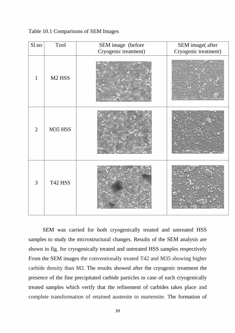
Table 10.1 Comparisons of SEM Images
Sl.no Tool SEM image (before
Cryogenic treatment)
SEM image( after
Cryogenic treatment)
1
M2 HSS
2
M35 HSS
3
T42 HSS
SEM was carried for both cryogenically treated and untreated HSS
samples to study the microstructural changes. Results of the SEM analysis are
shown in fig. for cryogenically treated and untreated HSS samples respectively
From the SEM images the conventionally treated T42 and M35 showing higher
carbide density than M2. The results showed after the cryogenic treatment the
presence of the fine precipitated carbide particles in case of each cryogenically
treated samples which verify that the refinement of carbides takes place and
complete transformation of retained austenite to martensite. The formation of
40
high carbide contraction will increase wear resistance, reduce friction, and
improves stability.
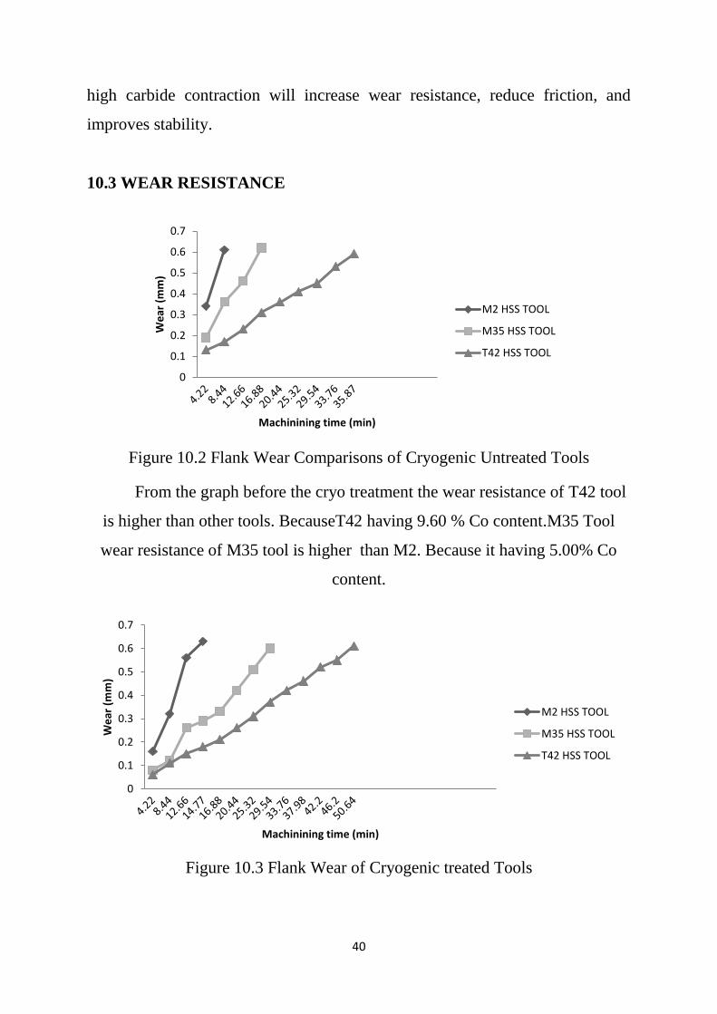
10.3 WEAR RESISTANCE
Figure 10.2 Flank Wear Comparisons of Cryogenic Untreated Tools
From the graph before the cryo treatment the wear resistance of T42 tool
is higher than other tools. BecauseT42 having 9.60 % Co content.M35 Tool
wear resistance of M35 tool is higher than M2. Because it having 5.00% Co
content.
Figure 10.3 Flank Wear of Cryogenic treated Tools
0
0.1
0.2
0.3
0.4
0.5
0.6
0.7
We
ar (
mm
)
Machinining time (min)
M2 HSS TOOL
M35 HSS TOOL
T42 HSS TOOL
0
0.1
0.2
0.3
0.4
0.5
0.6
0.7
We
ar (
mm
)
Machinining time (min)
M2 HSS TOOL
M35 HSS TOOL
T42 HSS TOOL
41
From the graph the wear resistance of cryogenic treated T42 tool is higher
than other cryogenic treated tools. By using cryogenic treatment tool life of all
tools improved.M35 Tool and M2 Tool have higher wear resistance after the
cryotreatment.
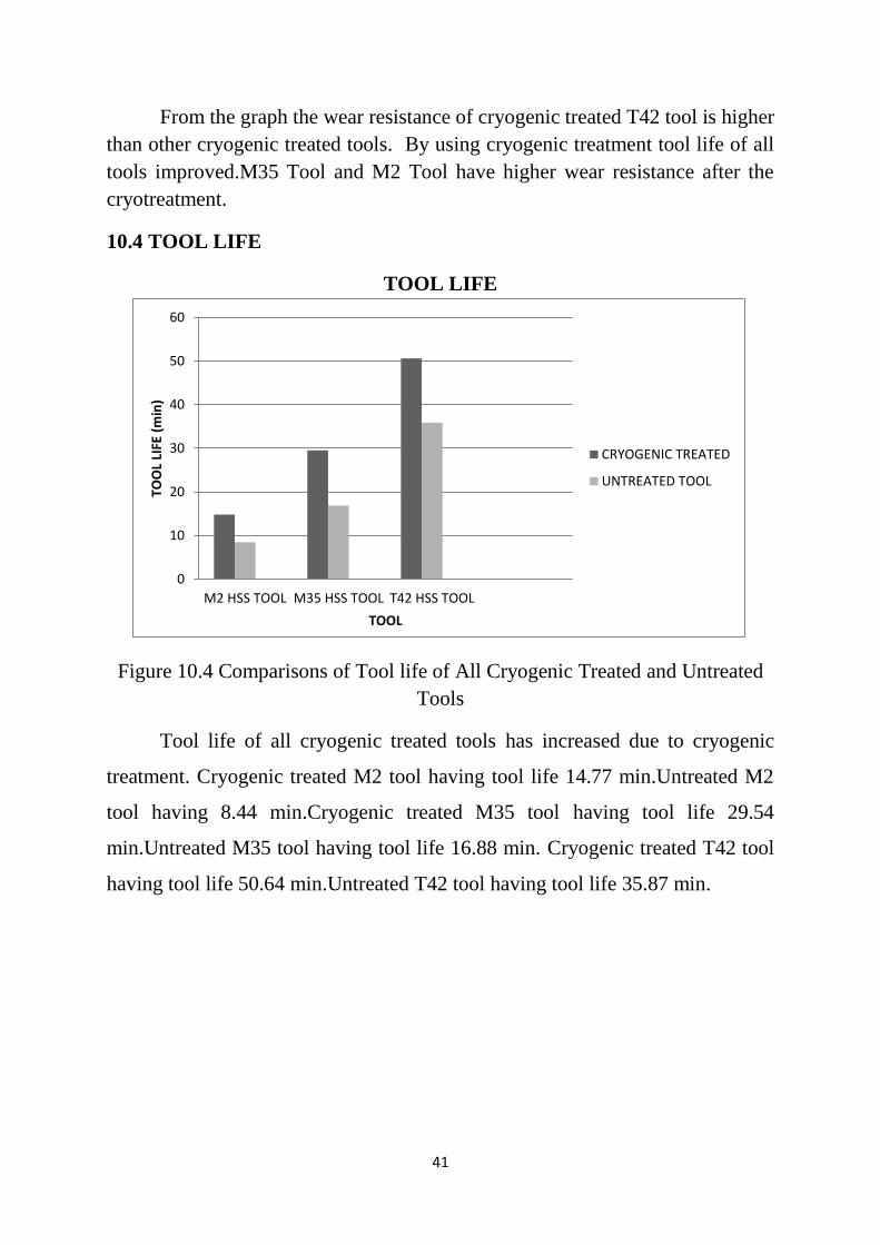
10.4 TOOL LIFE
TOOL LIFE
Figure 10.4 Comparisons of Tool life of All Cryogenic Treated and Untreated
Tools
Tool life of all cryogenic treated tools has increased due to cryogenic
treatment. Cryogenic treated M2 tool having tool life 14.77 min.Untreated M2
tool having 8.44 min.Cryogenic treated M35 tool having tool life 29.54
min.Untreated M35 tool having tool life 16.88 min. Cryogenic treated T42 tool
having tool life 50.64 min.Untreated T42 tool having tool life 35.87 min.
0
10
20
30
40
50
60
M2 HSS TOOL M35 HSS TOOL T42 HSS TOOL
TOO
L LI
FE (
min
)
TOOL
CRYOGENIC TREATED
UNTREATED TOOL
42
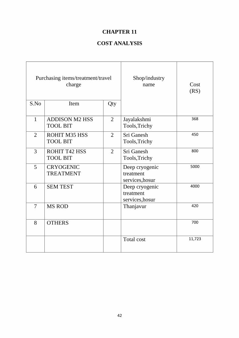
CHAPTER 11
COST ANALYSIS
Purchasing items/treatment/travel
charge
Shop/industry
name
Cost
(RS)
S.No Item Qty
1 ADDISON M2 HSS
TOOL BIT
2 Jayalakshmi
Tools,Trichy
368
2 ROHIT M35 HSS
TOOL BIT
2 Sri Ganesh
Tools,Trichy
450
3 ROHIT T42 HSS
TOOL BIT
2 Sri Ganesh
Tools,Trichy
800
5 CRYOGENIC
TREATMENT
Deep cryogenic
treatment
services,hosur
5000
6 SEM TEST Deep cryogenic
treatment
services,hosur
4000
7 MS ROD Thanjavur 420
8 OTHERS 700
Total cost 11,723
43
CHAPTER 12
CONCLUSION
From SEM analysis, it is evident that refinement of carbides is more in
cryogenically treated HSS tools comparison with untreated tools. While
doing hardness test, the hardness of Cryogenic treated HSS tools increased
compared with untreated HSS tools.The tool life is increased for M2 grade
HSS cutting tools, M35 grade HSS cutting tools and T42 grade HSS cutting
tools after the cryogenic treatment. From wear test, the wear resistance of
cryogenic treated HSS tools increased when compared with untreated HSS
tools. For all grades (M2, M35 &T42), Cryogenic process helped to improve
hardness and wear resistance. Thus cryogenic treatment of HSS tools is an
effective method to improve tool life performance.
44
REFERENCES
1. Avner, S.H. (1982) „Introduction to Physical Metallurgy‟, New York:
McGraw-Hill.
2. Barron R.F. (1982) „Cryogenic Treatment Of Metals To Improve Wear
Resistance‟, Cryogenics, pp. 409–413.
3. Barron R.F.(1974) „Yes Cryogenic Treatment Save You Money Heres
Why‟,Tapi Volume. No 57, pp.35-40.
4. Dhokey, N. B. (May 2014) „Cryogenic treatment for tool Steels‟ Steel
World.
5. Dong, Lin ,Xiao, (1998) “Deep Cryogenic Treatment Of High-Speed
Steel And Its Mechanism”. Heat Treatment Of Metals,Vol.3, pp. 55–59.
6. Huang, Zhu, Liao, Beyerlein,. Bourke, M.A. And Mitchell, T.E.
(2003)„Microstructure Of Cryogenic Treated M2 Tool Steel‟material Sci.
Eng, pp. 241–244.
7. Lakhwinder Pal Singh,Jagtar Singh,(Dec 2011) „Effect Of Cryogenic
Treatment On High Speed Steel Tools‟ Journal Of engineering And
Technology ,Vol 1.
8. Mohan Lal, D. , Renganarayanan. Kalanidhi, „Cryogenic Treatment To
Augment Wear Resistance Of Tool And Die Steels‟, Cryogenics.Vol .41,
pp. 149–155.
9. Paulin,(1993) „Frozen Gears‟, Gear Technol, pp. 26–28.
10. Smolnikov, C. And Kossovich, M. (1980) „Cold Treatment Of Cutting
Tools‟ Vol. 10, pp.5–7.
11. Swarndeep Singh1, Simranpreet Singh And Jagdev Singh2,(Dec 2015)
„Improvement In Tool Life Of M2hss Tools‟ International Journal Of
Materials And Mechanical Engineering.
12. Vaccari, J.A. (1986) „Deep Freeze Improves Products‟,Amer.Machinist
Automated Manufacturing.
13. George,E.Totten,HongLiang(1989)„MechanicalTribology:Materials,chara
cterization,and Applications‟pp 141.