Challenger MT 7XXC and MT 8XXC Series SmarTrax ...
27
Challenger MT 7XXC and MT 8XXC Series SmarTrax™ Installation Manual P/N 016-0197-003 Rev B 09/15 E17422 Copyright 2011, 2015
Transcript of Challenger MT 7XXC and MT 8XXC Series SmarTrax ...

Challenger MT 7XXC and MT 8XXC Series
SmarTrax™ Installation Manual
P/N 016-0197-003 Rev B 09/15 E17422
Copyright 2011, 2015

While every effort has been made to ensure the accuracy of this document, Raven Industries assumes no responsibility for omissions and errors. Nor is any liability assumed for damages resulting from the use of information contained herein.
Raven Industries shall not be responsible or liable for incidental or consequential damages or a loss of anticipated benefits or profits, work stoppage or loss, or impairment of data arising out of the use, or inability to use, this system or any of its components. Raven Industries shall not be held responsible for any modifications or repairs made outside our facilities, nor damages resulting from inadequate maintenance of this system.
As with all wireless and satellite signals, several factors may affect the availability and accuracy of wireless and satellite navigation and correction services (e.g. GPS, GNSS, SBAS, etc.). Therefore, Raven Industries cannot guarantee the accuracy, integrity, continuity, or availability of these services and cannot guarantee the ability to use Raven systems, or products used as components of systems, which rely upon the reception of these signals or availability of these services. Raven Industries accepts no responsibility for the use of any of these signals or services for other than the stated purpose.
Disclaimer

Table of Contents
Manual No. 016-0197-003 i
Chapter 1 Important Safety Information................................................. 3Important Safety Information ..................................................................................................... 3
Chapter 2 Introduction............................................................................. 5Introduction ............................................................................................................................... 5
Recommendations .............................................................................................................. 6Tools Needed ...................................................................................................................... 6Preparing for Installation ..................................................................................................... 6
Chapter 3 Installing SmarTrax with Cruizer II, Envizio Pro, or Viper Pro 7
SmarTrax Kit Contents .............................................................................................................. 7SmarTrax 3D ...................................................................................................................... 7Standard Node Mounting Kit ............................................................................................... 8
Install the SmarTrax Equipment ................................................................................................ 8Steering-Only Systems ...................................................................................................... 10Steering with Additional Nodes .......................................................................................... 10
Chapter 4 Installing SmarTrax with Cruizer......................................... 11SmarTrax Kit Contents ............................................................................................................ 11
SmarTrax 3D - Cruizer ..................................................................................................... 11SmarTrax - Cruizer ............................................................................................................ 12Standard Node Mounting Kit ............................................................................................. 13
Install the SmarTrax Equipment .............................................................................................. 13Install the Cruizer Equipment .................................................................................................. 15
Chapter 5 Wiring Schematics................................................................ 17SmarTrax Wiring Schematics .................................................................................................. 17
Viper Pro, Envizio Pro, Envizio Pro II, and Cruizer II ........................................................ 18Cruizer with Phoenix 200 SmarTrax Node ........................................................................ 19Cruizer with Phoenix 300 SmarTrax Node ........................................................................ 20Cruizer with Helix Antenna SmarTrax Node ...................................................................... 21

Table of Contents
ii Challenger MT 7XXC and MT 8XXC Series SmarTrax Installation Manuall

CHAPTER
1
Manual No. 016-0197-003 3
Chapter 1Important Safety Information
Important Safety Information
Read this manual and the operation and safety instructions included with your implement and/or controller carefully before installing the Steering Control system.
• Follow all safety information presented within this manual.• Follow all safety labels affixed to the Steering Control system components. Be sure to keep safety labels in
good condition and replace any missing or damaged labels. To obtain replacements for missing or damaged safety labels, contact your local Raven dealer.
• If you require assistance with any portion of the installation or service of your Raven equipment, contact your local Raven dealer for support.
When operating the machine after installing the Steering Control system, observe the following safety measures”
• Be alert and aware of surroundings.• Do not operate the Steering Control system or any agricultural equipment while under the influence of
alcohol or an illegal substance.• Remain in the operator’s position in the machine at all times when the Steering Control system is engaged.• Disable the Steering Control system when exiting the operator’s seat and machine.• Do not drive the machine with the Steering Control system enabled on any public road.• Determine and remain a safe working distance from other individuals. The operator is responsible for
disabling the Steering Control system when the safe working distance has been diminished.• Ensure the Steering Control system is disabled prior to beginning any maintenance work on the Steering
Control system or the machine.
NOTICE

Chapter 1
4 Challenger MT 7XXC and MT 8XXC Series SmarTrax Installation Manual
• When starting the machine for the first time after installing the Steering Control system, be sure that all persons are standing clear of the machine in case a wheel moves unexpectedly.
• Read all safety requirements and precautions in the machine’s operation manual prior to operating a machine equipped with the Steering Control system feature. Failure to follow safety precautions may lead to damage to the equipment, personal injury, or death.
• To prevent accidental engagement of steering and loss of vehicle control, turn the road switch on when driving down the road.
• The GPS steering system does not detect obstacles in the vehicle’s path. The operator must observe the path being driven to avoid obstacles.
• When engaged, the GPS steering system controls only the steering of the vehicle. The operator must control the speed of the vehicle.
WARNING
CAUTION

CHAPTER
2
Manual No. 016-0197-003 5
Chapter 2Introduction
IntroductionCongratulations on your purchase of the Raven Steering Control system! This system is designed to provide cutting-edge, hands-free steering of your machine via Global Positioning System (GPS) coordinates.
This manuals applies to the following machines. For future reference, write your serial number in the space below.
MAKE: Cat Challenger MODEL: MT 7XXC and MT 8XXCYEAR: SERIAL NUMBER:
FIGURE 1. Cat Challenger MT Series

Chapter 2
6 Challenger MT 7XXC and MT 8XXC Series SmarTrax Installation Manual
Recommendations
Raven Industries recommends the following best practices when installing the Steering Control system:
• Use part numbers to identify the parts.• Do not remove the plastic wrap from a part until it is necessary for installation.
Tools Needed
The following tools may be needed for installation of the Steering Control system:
• Screwdrivers of various sizes• SAE standard-sized wrenches• Allen wrenches• Side cutters• Pliers
Preparing for Installation
Leave the machine turned off for the duration of the installation process. During the installation process, follow good safety practices. Be sure to carefully read the instructions in this manual as you complete the installation process.
CHAPTER
3
Manual No. 016-0197-003 7
Chapter 3Installing SmarTrax with Cruizer II, Envizio Pro, or Viper Pro
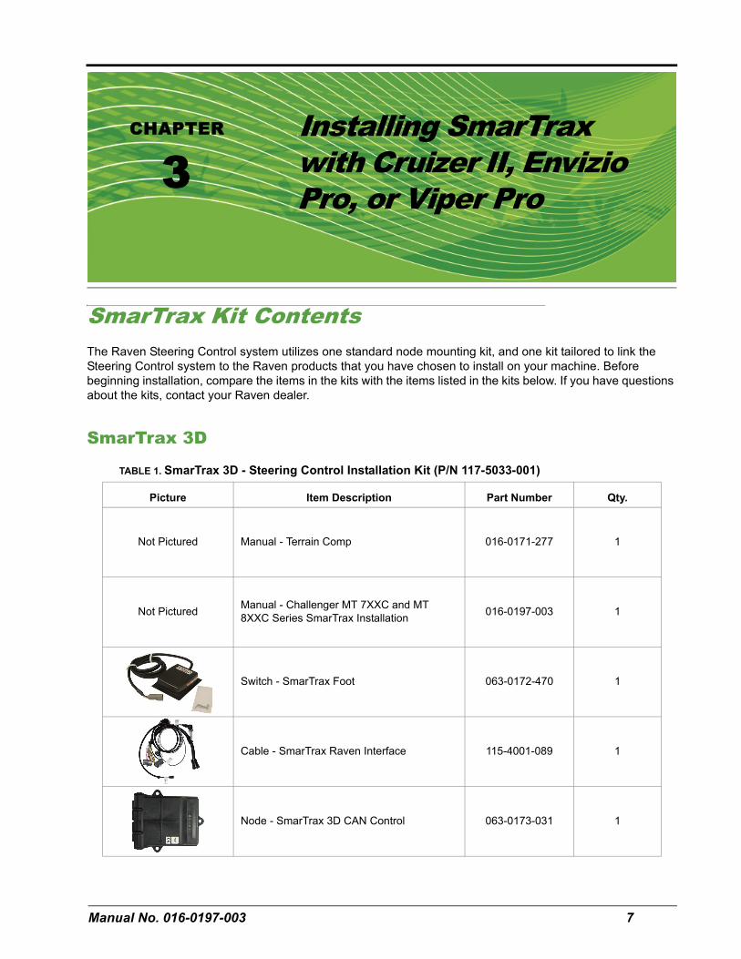
SmarTrax Kit ContentsThe Raven Steering Control system utilizes one standard node mounting kit, and one kit tailored to link the Steering Control system to the Raven products that you have chosen to install on your machine. Before beginning installation, compare the items in the kits with the items listed in the kits below. If you have questions about the kits, contact your Raven dealer.
SmarTrax 3D
TABLE 1. SmarTrax 3D - Steering Control Installation Kit (P/N 117-5033-001)
Picture Item Description Part Number Qty.
Not Pictured Manual - Terrain Comp 016-0171-277 1
Not Pictured Manual - Challenger MT 7XXC and MT 8XXC Series SmarTrax Installation 016-0197-003 1
Switch - SmarTrax Foot 063-0172-470 1
Cable - SmarTrax Raven Interface 115-4001-089 1
Node - SmarTrax 3D CAN Control 063-0173-031 1

Chapter 3
8 Challenger MT 7XXC and MT 8XXC Series SmarTrax Installation Manual
Standard Node Mounting Kit
Install the SmarTrax EquipmentImportant: The Challenger Armrest ECU must be updated to version 2.19 or greater in
order to work with the SmarTrax system. Contact your local AGCO or CAT dealer to obtain the software update.
FIGURE 1. Node Installed on Mounting Plate
1. Mount the SmarTrax node (P/N 063-0173-031) to the mounting plate (P/N 107-0171-888) using three 3/8”-16 x 1-1/4” hex bolts (P/N 311-0054-106) and three 3/8”-16 UNC nylon lock nuts (P/N 312-4000-061).
TABLE 2. Standard Steering Control Node Mounting Kit (P/N 117-0197-051)
Picture Item Description Part Number Qty.
Bracket - Challenger Mounting 107-0171-888 1
Bolt - 3/8”-16 x 1-1/4” Hex 311-0054-106 3
Nut - 3/8”-16 UNC Nyloc Lock 312-4000-061 3

3
Manual No. 016-0197-003 9
Installing SmarTrax with Cruizer II, Envizio Pro, or Viper Pro
FIGURE 2. Mounting Plate Example
2. Remove the two bolts from monitor mounting bracket.3. Slide the node mount behind the monitor mounting bracket and replace the bolts as shown in Figure 2.
FIGURE 3. Raven Interface Cable Connected
4. Insert the large, rectangular node connectors on the harness cable (P/N 115-4001-089) into the correct ports of the SmarTrax node.
FIGURE 4. CAT CAN Connectors
5. Locate the Challenger CANbus connectors in the side panel, break the connection, and install the Raven cable.
Before After

Chapter 3
10 Challenger MT 7XXC and MT 8XXC Series SmarTrax Installation Manual
FIGURE 5. Foot Switched Installed
6. Mount the foot switch to the floor of the cab using screws or double-sided tape (not included in the installation kit).
Note: The foot switch should be mounted in a location that allows the front of the pedal to be fully pressed without interference.
7. Connect the foot switch to the node cable.
Steering-Only Systems
On systems using the 115-4001-085 chassis cable, leave the jumper plug on the connector labeled “To SmarTrax Node.” Install the 115-4001-089 harness cable between the 115-4001-085 chassis cable and the console cable (P/N 115-0171-926 or 115-4001-066).
Steering with Additional Nodes
On systems using multiple Raven nodes, install the 115-4001-089 harness cable between the chassis cable (P/N 115-0171-915) and the console cable (P/N 115-0171-926).

CHAPTER
4
Manual No. 016-0197-003 11
Chapter 4Installing SmarTrax with Cruizer
SmarTrax Kit ContentsThe Raven Steering Control system utilizes one standard node mounting kit, and one kit tailored to link the Steering Control system to the Raven products that you have chosen to install on your machine. Before beginning installation, compare the items in the kits with the items listed in the kits below. If you have questions about the kits, contact your Raven dealer.
Note: This section contains the kit contents for several different Raven product combinations. Be sure to identify the correct kit for the products being installed on the machine.
SmarTrax 3D - Cruizer
TABLE 1. SmarTrax 3D - Cruizer Steering Control Installation Kit (P/N 117-0197-054)
Picture Item Description Part Number Qty.
Not Pictured Manual - Terrain Comp 016-0171-277 1
Not Pictured Manual - Challenger MT 7XXC and MT 8XXC Series SmarTrax Installation 016-0197-003 1
Switch - SmarTrax Foot 063-0172-470 1

Chapter 4
12 Challenger MT 7XXC and MT 8XXC Series SmarTrax Installation Manual
SmarTrax - Cruizer
Cable - Steiger/Quadtrac the Steering Control system with Cruizer Raven Interface 115-4001-025 1
Node - SmarTrax 3D CAN Control 063-0173-031 1
TABLE 2. SmarTrax - Cruizer Steering Control Installation Kit (P/N 117-0197-055)
Picture Item Description Part Number Qty.
Not Pictured Manual - Terrain Comp 016-0171-277 1
Not Pictured Manual - Challenger MT 7XXC and MT 8XXC Series SmarTrax Installation 016-0197-003 1
Switch - SmarTrax Foot 063-0172-470 1
Node - SmarTrax CAN Control 063-0173-042 1
Cable - SmarTrax Node Raven Interface 115-4001-025 1
TABLE 1. SmarTrax 3D - Cruizer Steering Control Installation Kit (P/N 117-0197-054)
Picture Item Description Part Number Qty.

4
Manual No. 016-0197-003 13
Installing SmarTrax with Cruizer
Standard Node Mounting Kit
Install the SmarTrax EquipmentImportant: The Challenger Armrest ECU must be updated to version 2.19 or greater in
order to work with the SmarTrax system. Contact your local AGCO or CAT dealer to obtain the software update.
FIGURE 1. Node Installed on Mounting Plate
1. Mount the SmarTrax node (P/N 063-0173-031) to the mounting plate (P/N 107-0171-888) using three 3/8”-16 x 1-1/4” hex bolts (P/N 311-0054-106) and three 3/8”-16 UNC nylon lock nuts (P/N 312-4000-061).
TABLE 3. Standard Steering Control Node Mounting Kit (P/N 117-0197-051)
Picture Item Description Part Number Qty.
Bracket - Challenger Mounting 107-0171-888 1
Bolt - 3/8”-16 x 1-1/4” Hex 311-0054-106 3
Nut - 3/8”-16 UNC Nyloc Lock 312-4000-061 3

Chapter 4
14 Challenger MT 7XXC and MT 8XXC Series SmarTrax Installation Manual
FIGURE 2. Mounting Plate Example
2. Remove the two bolts from monitor mounting bracket and mount the node as shown.
FIGURE 3. Raven Interface Cable Connected
3. Insert the large, rectangular node connectors on the harness cable (P/N 115-4001-025) into the correct ports of the SmarTrax node.
4. Remove the side panel and locate the 3 pin power connector.
FIGURE 4. Power Connector

Manual No. 016-0197-003 15
Installing SmarTrax with Cruizer
5. Remove protective cover and connect to the Raven cable.6. Locate the Challenger CANbus connectors in the side panel.
FIGURE 5. CAT CAN Connectors
7. Break the connectors and connect the Raven cable.
FIGURE 6. Foot Switched Installed
8. Mount the foot switch to the floor of the cab using screws or double-sided tape (not included in the installation kit).
Note: The foot switch should be mounted in a location that allows the front of the pedal to be fully pressed without interference.
9. Connect the foot switch to the node cable.
Install the Cruizer Equipment1. Connect the display cable to the Cruizer port A (the connector underneath the coaxial antenna connector).2. Connect the DGPS out connector to supplied Cruizer cable (P/N 115-0171-796).3. Connect GPS source to the cable labeled DGPS.
Before After

Chapter 4
16 Challenger MT 7XXC and MT 8XXC Series SmarTrax Installation Manual

CHAPTER
5
Manual No. 016-0197-003 17
Chapter 5Wiring Schematics
SmarTrax Wiring SchematicsRefer to the Installation & Operation Manual and the appropriate wiring schematic in this chapter for the installation and wiring instructions for your specific field computer.

Chapter 5
18 Challenger MT 7XXC and MT 8XXC Series SmarTrax Installation Manual
Viper Pro, Envizio Pro, Envizio Pro II, and Cruizer II

5
Manual No. 016-0197-003 19
Wiring Schematics
Cruizer with Phoenix 200 SmarTrax Node

Chapter 5
20 Challenger MT 7XXC and MT 8XXC Series SmarTrax Installation Manual
Cruizer with Phoenix 300 SmarTrax Node

5
Manual No. 016-0197-003 21
Wiring Schematics
Cruizer with Helix Antenna SmarTrax Node

Chapter 5
22 Challenger MT 7XXC and MT 8XXC Series SmarTrax Installation Manual
Index
Manual No. 016-0197-003 23
IInstalling SmarTrax with Cruizer 11
Installing the Cruizer Equipment 15Installing the SmarTrax Equipment 13SmarTrax Kit Contents 11
Installing SmarTrax with Cruizer II, Envizio Pro, and Viper Pro
Installing the SmarTrax Equipment 8SmarTrax Kit Contents 7Steering with Additional Nodes 10Steering-Only Systems 10
Installing SmarTrax with Cruizer II, Envizio Pro, or Viper Pro 7
Introduction 5Preparing for Installation 6Recommendations 6Tools Needed 6
WWiring Schematics 17
CruizerHelix Antenna SmarTrax Node 21Phoenix 200 SmarTrax Node 19Phoenix 300 SmarTrax Node 20
Viper Pro, Envizio Pro, Envizio Pro II, and Cruizer II 18

Index
24 Challenger MT 7XXC and MT 8XXC Series SmarTrax Installation Manual

Raven Industries will not assume any expense or liability for repairs made outside our facilities without written consent. Raven Industries is not responsible for damage to any associated equipment or products and will not be liable for loss of profit or other special damages. The obligation of this warranty is in lieu of all other warranties, expressed or implied, and no person or organization is
authorized to assume any liability for Raven Industries.
Damages caused by normal wear and tear, misuse, abuse, neglect, accident, or improper installation and maintenance are not covered
by this warranty.
What Does this Warranty Cover?
How Long is the Coverage Period?
How Can I Get Service?
What Will Raven Industries Do?
What is not Covered by this Warranty?
Bring the defective part and proof of purchase to your Raven dealer.If your dealer agrees with the warranty claim, the dealer will send the part and proof of purchase to their distributor or to Raven Industries
for final approval.
Upon confirmation of the warranty claim, Raven Industries will, at our discretion, repair or replace the defective part and pay for return
freight.
RAVEN INDUSTRIESLimited Warranty
This warranty covers all defects in workmanship or materials in your Raven Applied Technology Division product under normal use,
maintenance, and service.
Raven Applied Technology Division products are covered by this warranty for 12 months after the date of purchase. This warranty coverage applies only to the original owner and is nontransferable.