CG Tutorial Project - 3D Renderer (Ray Tracing Engine)fengqian/cg/CGTutorialProj3_doc_en.pdf ·...
21
Tutorial Project of Computer Graphics – 3D Renderer (Ray Tracing Engine) Feng Qian, June 2006 Page 1/21 Tutorial Project of Computer Graphics 3D Renderer (Ray Tracing Engine) Feng Qian Computer Science & Engineering Department, SJTU [email protected] June 2006 l Developing Environment and Tools Windows XP Professional SP2 Visual C++.NET 2003 (MFC) OpenGL 1.1 Mathematica 4.2 (Math Tool) Approximate 12000 lines of source code l User Interface Modeling Interface
Transcript of CG Tutorial Project - 3D Renderer (Ray Tracing Engine)fengqian/cg/CGTutorialProj3_doc_en.pdf ·...

Tutorial Project of Computer Graphics – 3D Renderer (Ray Tracing Engine) Feng Qian, June 2006
Page 1/21
Tutorial Project of Computer Graphics 3D Renderer (Ray Tracing Engine)
Feng Qian Computer Science & Engineering Department, SJTU [email protected]
June 2006
l Developing Environment and Tools Windows XP Professional SP2 Visual C++.NET 2003 (MFC) OpenGL 1.1 Mathematica 4.2 (Math Tool) Approximate 12000 lines of source code l User Interface
Modeling Interface

Tutorial Project of Computer Graphics – 3D Renderer (Ray Tracing Engine) Feng Qian, June 2006
Page 2/21
Rendering Result
l Features 1. The modeling system adopts the same interface used in my Tutorial Project 2 of CG (3D
Drawing Pad of Curves and Surfaces), which uses an auxiliary plane to position control points in 3D space;
2. Drawing and rendering planes, parallelepipeds, tetrahedrons, pyramids, spheres, cylinders and cones;
3. Multiple light sources are supported; 4. Fast ray tracing algorithm, the normal rendering process is finished in 15 seconds; 5. Ambient light is supported; 6. Light source attenuation is supported; 7. Shadows are supported; 8. Transparency is supported; 9. Diffusive reflection is supported; 10. Specular reflection is supported; 11. Simple refraction effect: do not take account of refractive index; 12. Advanced refraction effect: do take account of refractive index; 13. Setting diffusive index, transparent index, specular reflection index, specular reflection
exponent and refractive index for each object;
Tutorial Project of Computer Graphics – 3D Renderer (Ray Tracing Engine) Feng Qian, June 2006
Page 3/21
14. Setting max height of ray tree, global ambient light and light source attenuation equation; 15. Save rendering result as Windows BMP files. l Algorithms 1. Illumination Equation
Whitted’s illumination Equation (P.511, [2], Formula 14.32)
1
[ ( ) ( ) ]i i
mn
a a d i att p d d i s i s r t ti
I I k O S f I k O N L k N H k I k Iλ λ λ λ λ λ λ=
= + + + +∑ i i
Please refer [2] for details.
2. Ray Tracing Algorithm Recursive ray tracing algorithm without antialiasing (P.513, [2], Algorithm 14.1, with several improvements)
3. Other algorithms of Computer Graphics and Computing Geometry Dot product and cross product of vectors; Geometrical transformations (translating, scaling and rotating); Intersecting testing of point and line; Intersecting testing of lines; Computing interesting point of lines and planes, polyhedrons, cylinders, cones; Computing normal vectors of planes, polyhedrons, cylinders and cones; Convex hall algorithm.
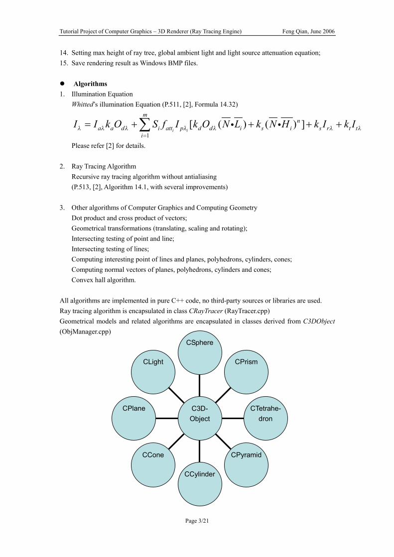
All algorithms are implemented in pure C++ code, no third-party sources or libraries are used. Ray tracing algorithm is encapsulated in class CRayTracer (RayTracer.cpp) Geometrical models and related algorithms are encapsulated in classes derived from C3DObject (ObjManager.cpp)
CLight
CPlane
CCone
CCylinder
CPyramid
CTetrahe-dron
CPrism
CSphere
C3D- Object
Tutorial Project of Computer Graphics – 3D Renderer (Ray Tracing Engine) Feng Qian, June 2006
Page 4/21
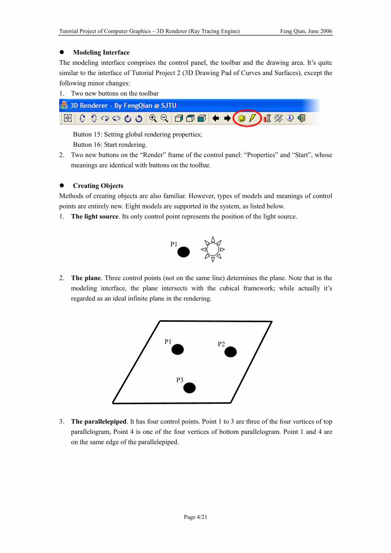
l Modeling Interface The modeling interface comprises the control panel, the toolbar and the drawing area. It’s quite similar to the interface of Tutorial Project 2 (3D Drawing Pad of Curves and Surfaces), except the following minor changes: 1. Two new buttons on the toolbar
Button 15: Setting global rendering properties; Button 16: Start rendering. 2. Two new buttons on the “Render” frame of the control panel: “Properties” and “Start”, whose
meanings are identical with buttons on the toolbar. l Creating Objects Methods of creating objects are also familiar. However, types of models and meanings of control points are entirely new. Eight models are supported in the system, as listed below. 1. The light source. Its only control point represents the position of the light source.
2. The plane. Three control points (not on the same line) determines the plane. Note that in the
modeling interface, the plane intersects with the cubical framework; while actually it’s regarded as an ideal infinite plane in the rendering.
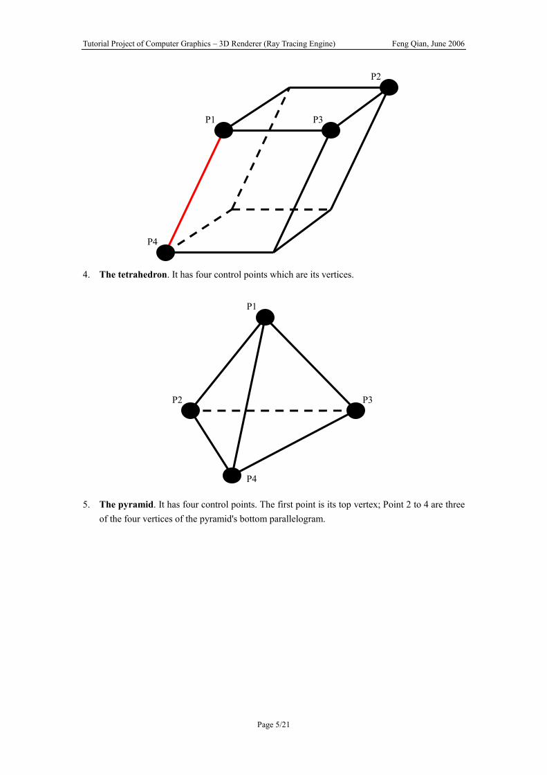
3. The parallelepiped. It has four control points. Point 1 to 3 are three of the four vertices of top
parallelogram, Point 4 is one of the four vertices of bottom parallelogram. Point 1 and 4 are on the same edge of the parallelepiped.
P1
P1 P2
P3
Tutorial Project of Computer Graphics – 3D Renderer (Ray Tracing Engine) Feng Qian, June 2006
Page 5/21
4. The tetrahedron. It has four control points which are its vertices.
5. The pyramid. It has four control points. The first point is its top vertex; Point 2 to 4 are three
of the four vertices of the pyramid's bottom parallelogram.
P2
P1 P3
P4
P1
P2 P3
P4

Tutorial Project of Computer Graphics – 3D Renderer (Ray Tracing Engine) Feng Qian, June 2006
Page 6/21
6. The sphere. It has two control points. The first point is its center; the second one can be any
point on the spherical surface.
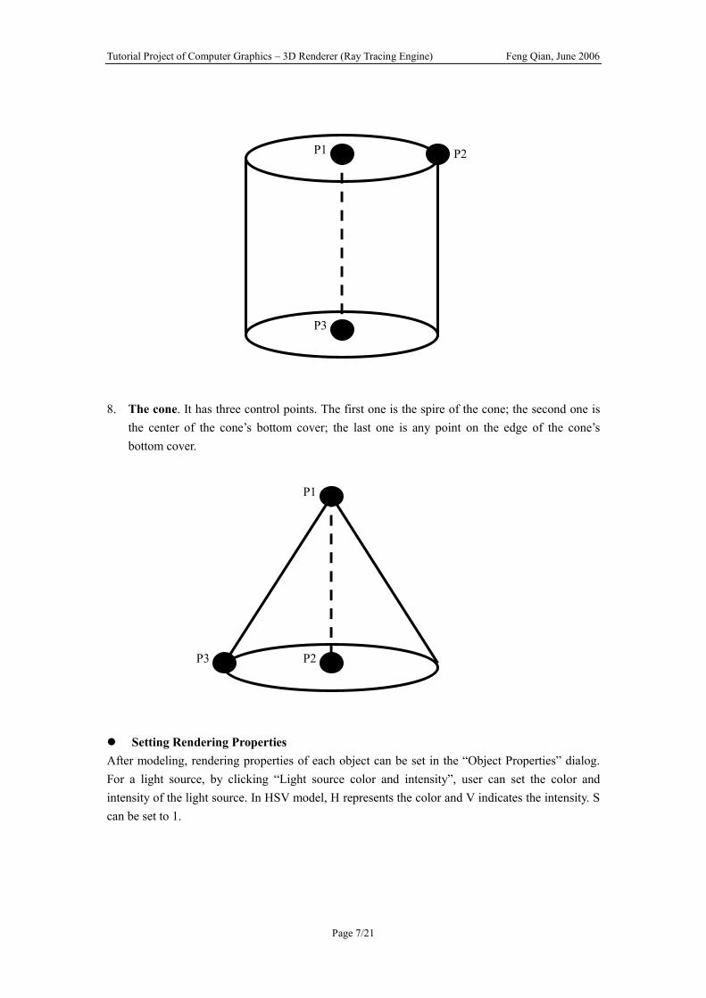
7. The cylinder. It has three control points. The first one is the center of the cylinder's top cover;
the second one is any point on the edge of the cylinder's top cover; the last one is the center of the cylinder's bottom cover.
P1
P2 P3
P4
P1
P2
Tutorial Project of Computer Graphics – 3D Renderer (Ray Tracing Engine) Feng Qian, June 2006
Page 7/21
8. The cone. It has three control points. The first one is the spire of the cone; the second one is
the center of the cone’s bottom cover; the last one is any point on the edge of the cone’s bottom cover.
l Setting Rendering Properties After modeling, rendering properties of each object can be set in the “Object Properties” dialog. For a light source, by clicking “Light source color and intensity”, user can set the color and intensity of the light source. In HSV model, H represents the color and V indicates the intensity. S can be set to 1.
P1 P2
P3
P1
P2 P3

Tutorial Project of Computer Graphics – 3D Renderer (Ray Tracing Engine) Feng Qian, June 2006
Page 8/21
For other geometry objects, five properties can be set by clicking “Rendering Properties”.
Diffusive Index: a real number between 0 and 1. The greater the number is, the
more notably the diffusive light reflects; Transparent Index: a real number between 0 and 1. The greater the number is, the
more transparent the object looks; Specular Reflection Index: a real number between 0 and 1. The greater the number is, the
more notably the specular light reflects; Specular Reflection Exponent: a positive integer. It’s the exponent of the product of reflection
Tutorial Project of Computer Graphics – 3D Renderer (Ray Tracing Engine) Feng Qian, June 2006
Page 9/21
vector and viewpoint vector in the illumination equation. The greater the exponent is, the more notably the highlight concentrates;
Refractive Index: a real number between 1 and 3. Its meaning is identical with the meaning of the refractive index in Snell’s Law.
Default values of these parameters are:
Parameter Default Value Diffusive Index 0.9 Transparent Index 0.0 Specular Reflection Index 0.0 Specular Reflection Exponent 3 Refractive Index 1.0
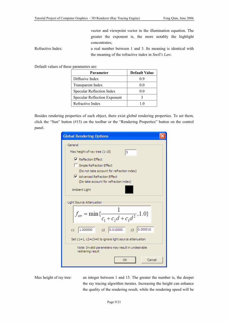
Besides rendering properties of each object, there exist global rendering properties. To set them, click the “Sun” button (#15) on the toolbar or the “Rendering Properties” button on the control panel.
Max height of ray tree: an integer between 1 and 15. The greater the number is, the deeper
the ray tracing algorithm iterates. Increasing the height can enhance the quality of the rendering result, while the rendering speed will be
Tutorial Project of Computer Graphics – 3D Renderer (Ray Tracing Engine) Feng Qian, June 2006
Page 10/21
slower. Reflection Effect: whether or not uses reflection effect; Simple Refraction Effect: whether or not uses refraction effect (do not take account of refractive index); Advanced Refraction Effect: whether or not uses refraction effect (do take account of refractive
index); at most one option between simple and advanced refraction effect should be chosen;
Ambient Light: the color and intensity of the ambient light. Normally, the ambient light should not be too bright;
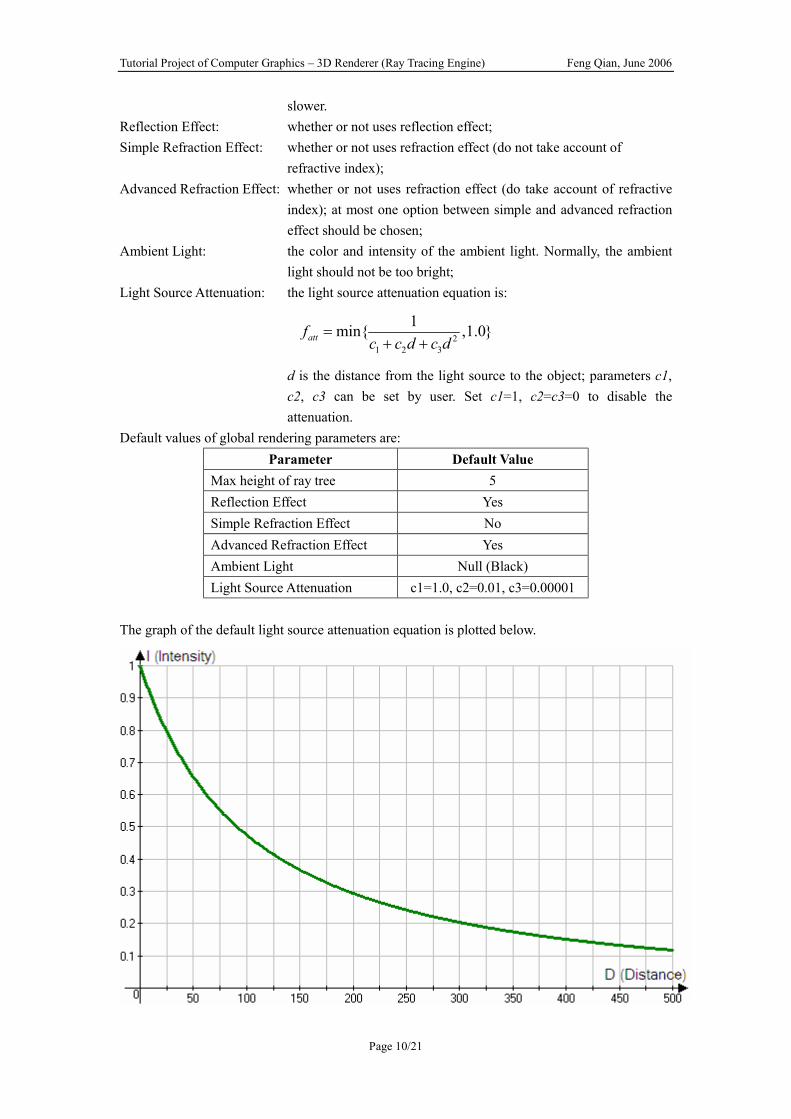
Light Source Attenuation: the light source attenuation equation is:
21 2 3
1min{ ,1.0}attfc c d c d
=+ +
d is the distance from the light source to the object; parameters c1, c2, c3 can be set by user. Set c1=1, c2=c3=0 to disable the attenuation.
Default values of global rendering parameters are: Parameter Default Value
Max height of ray tree 5 Reflection Effect Yes Simple Refraction Effect No Advanced Refraction Effect Yes Ambient Light Null (Black) Light Source Attenuation c1=1.0, c2=0.01, c3=0.00001
The graph of the default light source attenuation equation is plotted below.

Tutorial Project of Computer Graphics – 3D Renderer (Ray Tracing Engine) Feng Qian, June 2006
Page 11/21
l Start Rendering The user can start rendering by clicking the “lightning” button on the toolbar or “Start” button on the control panel. During the rendering progress, a progress bar will appear and the rendering can be cancelled by clicking the “Stop” button.
Seconds later, the rendering result window will be shown. Right click on the window can save the result as a Windows BMP file. As a summary, to render a scene, four steps are needed.
1. Creating and modifying models; 2. Setting rendering properties of each model (optional); 3. Setting global rendering properties (optional); 4. Start rendering.
l Troubleshooting 1. Problem: Message “One ActiveX component needed by this program is not registered” 2. The program runs slow 3. Anti-aliasing does not take effect
For problem 1~3 Please refer to the document of my Tutorial Project 2 of CG (3D Drawing Pad of Curves and Surfaces)
4. Nothing except color of ambient light can be seen in the rendering result Possible causes: Objects are obstructed by a plane; Light sources are too weak or are obstructed by other objects; Please note that in the rendering, a plane is infinite.
5. The rendering result is too bright Possible solutions: Decrease the number of light sources; Decrease the intensity of each light source; Decrease the diffusive reflection index and / or the specular reflection index of each object;
6. My video card is not very good. Will it affect the quality or speed of the rendering? No. The rendering progress of this program does not use any OpenGL or DirectX features, which may operate the video card. So the rendering quality of the same scene (including parameters) is identical on any machine. The speed only depends on the frequency of CPU.
l References 1. Geometric Tools for Computer Graphics Philip J.Schneider David H.Eberly

Tutorial Project of Computer Graphics – 3D Renderer (Ray Tracing Engine) Feng Qian, June 2006
Page 12/21
2. Introduction to Computer Graphics James D. Foley, Andries van Dam, Steven K. Feiner, John F. Hughes, Richard L. Phillips
3. Computer Graphics Principles and Practice, second edition in C James D. Foley, Andries van Dam, Steven K. Feiner, John F. Hughes, Richard L. Phillips
4. Computer Graphics Using OpenGL, Second Edition F.S. Hill, JR. 5. Computer Graphics with OpenGL, Third Edition Donald Hearn, M. Pauline Baker 6. OpenGL Programming Guide Fourth Edition
l Gallery
Simple Rendering – no reflection or refraction effect

Tutorial Project of Computer Graphics – 3D Renderer (Ray Tracing Engine) Feng Qian, June 2006
Page 13/21
Specular reflection – with highlight on the spherical surface
Tutorial Project of Computer Graphics – 3D Renderer (Ray Tracing Engine) Feng Qian, June 2006
Page 14/21
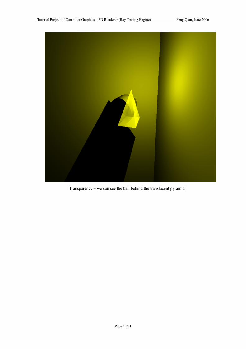
Transparency – we can see the ball behind the translucent pyramid
Tutorial Project of Computer Graphics – 3D Renderer (Ray Tracing Engine) Feng Qian, June 2006
Page 15/21
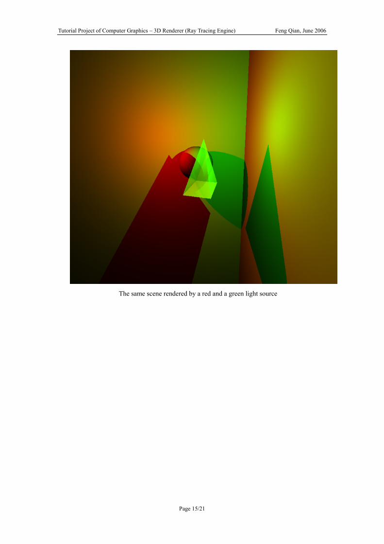
The same scene rendered by a red and a green light source
Tutorial Project of Computer Graphics – 3D Renderer (Ray Tracing Engine) Feng Qian, June 2006
Page 16/21
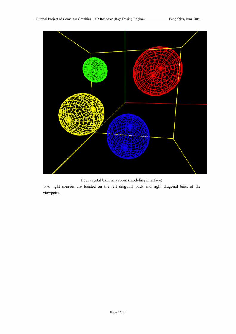
Four crystal balls in a room (modeling interface) Two light sources are located on the left diagonal back and right diagonal back of the viewpoint.

Tutorial Project of Computer Graphics – 3D Renderer (Ray Tracing Engine) Feng Qian, June 2006
Page 17/21
Four crystal balls in a room – rendering result Rendered with reflection and refraction effect

Tutorial Project of Computer Graphics – 3D Renderer (Ray Tracing Engine) Feng Qian, June 2006
Page 18/21
More crystal balls, rendered by three light sources (red, green and yellow)

Tutorial Project of Computer Graphics – 3D Renderer (Ray Tracing Engine) Feng Qian, June 2006
Page 19/21
Render balls with different specular exponents (SE)
Tutorial Project of Computer Graphics – 3D Renderer (Ray Tracing Engine) Feng Qian, June 2006
Page 20/21
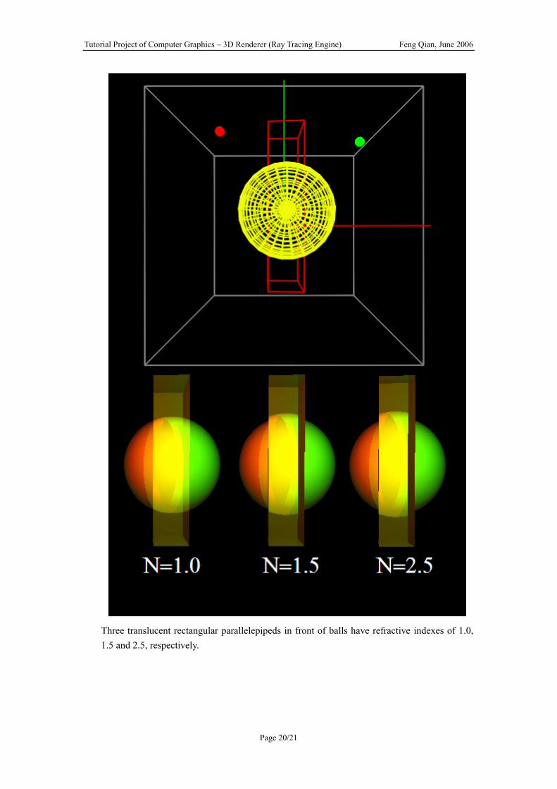
Three translucent rectangular parallelepipeds in front of balls have refractive indexes of 1.0, 1.5 and 2.5, respectively.

Tutorial Project of Computer Graphics – 3D Renderer (Ray Tracing Engine) Feng Qian, June 2006
Page 21/21
The planes and the pyramid have high diffusive indexes


![[DL輪読会]Neural 3d Mesh Renderer](https://static.fdocuments.us/doc/165x107/5aaa85d17f8b9af9198b4675/dlneural-3d-mesh-renderer.jpg)