
CeramCool The Ceramic System for High Power Packaging · The Ceramic System for High Power...
9
Electronic Applications Division T H E C E R A M I C E X P E R T S CeramCool ® The Ceramic System for High Power Packaging Wherever things get hot
Transcript of CeramCool The Ceramic System for High Power Packaging · The Ceramic System for High Power...

Electronic Applications Division
T H E C E R A M I C E X P E R T S
CeramCool®
The Ceramic System for High Power PackagingWherever things get hot
3
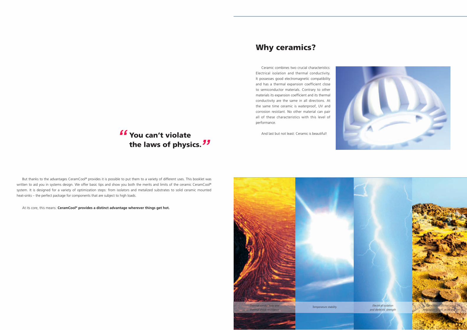
Why ceramics?
Ceramic combines two crucial characteristics:
Electrical isolation and thermal conductivity.
It possesses good electromagnetic compatibility
and has a thermal expansion coefficient close
to semiconductor materials. Contrary to other
materials its expansion coefficient and its thermal
conductivity are the same in all directions. At
the same time ceramic is waterproof, UV and
corrosion resistant. No other material can pair
all of these characteristics with this level of
performance.
And last but not least: Ceramic is beautiful!
Corrosion does not occur.
Resistance to salt, acids and lye.
Thermal conductivity and
thermal shock resistanceTemperature stability Electrical isolation
and dielectric strength
But thanks to the advantages CeramCool® provides it is possible to put them to a variety of different uses. This booklet was
written to aid you in systems design. We offer basic tips and show you both the merits and limits of the ceramic CeramCool®
system. It is designed for a variety of optimization steps: from isolators and metalized substrates to solid ceramic mounted
heat-sinks – the perfect package for components that are subject to high loads.
At its core, this means: CeramCool® provides a distinct advantage wherever things get hot.
You can’t violate the laws of physics.
“ ”
4 54 Cer
amC
oo
lC
eram
Co
ol®
Keep it simple.
It’s simple and extremely reliable. It offers a powerful solution
for thermally sensitive components and circuits thanks to its
excellent thermal conductivity and stability characteristics and its
compact form. CeramCool® is the ideal heat-sink or even packaging
system for high-power LEDs and high-power electronics.
Simplification and miniaturization
Heat-sensitive semi-conductor components are often mounted onto
conventional substrates. They need to provide electrical isolation while
ensuring adequate thermal conductivity. The result is frequently a kind of
“sandwich” with multiple layers made from different materials. Each layer is
a potential risk and poses an additional obstacle to thermal conductivity.
CeramCool® transforms the substrate into a heat-sink itself.
Excellent thermal management – long life
The simplified construction combined with a direct and permanent
bond between electronic component and CeramCool® create ideal
operating conditions. Put simply: What isn’t there won’t wear out and
materials that expand in proportion to each other won’t separate.
Delamination is no longer an issue. And running the system at a lower
temperature level increases life time.
Chip on heat-sink – optimized packaging
CeramCool® can be coated directly. The whole surface can be used as
a circuit carrier which can be firmly packed with components on customized
circuit layouts – while providing reliable electrical isolation. The process
can be simplified by bonding chips directly onto the specially designed
CeramCool® metallized surface. Chip on heat-sink! Compact and simple.
Heat-Sink
Glue
Conductor
PCB Substrate
LED
Typical packaging system with
multiple layers and different
TCEs.
Potential risks: Delamination,
corrosion, degradation.
Simpler and smaller System
with CeramCool®. Opti-
mized thermal management
with direct metal to metal
connection.Main Advan-
tages: Excellent long term
stability and high reliability.
Get close.
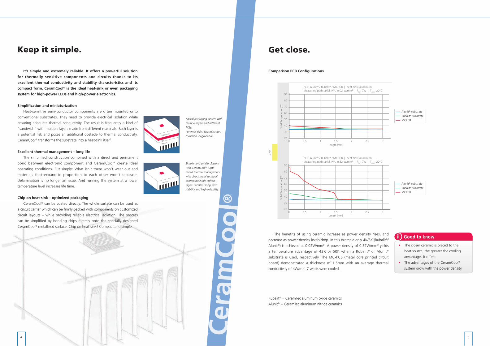
Comparison PCB Configurations
90
80
70
60
50
40
30
200,5 1 1,5 2 2,5 30
Length [mm]
Solid
Tem
pera
ture
[°C
]
90
80
70
60
50
40
30
200,5 1 1,5 2 2,5 30
Length [mm]
Solid
Tem
pera
ture
[°C
]
CH
IP
The benefits of using ceramic increase as power density rises, and
decrease as power density levels drop. In this example only 4K/6K (Rubalit®/
Alunit®) is achieved at 0.02W/mm². A power density of 0.32W/mm² yields
a temperature advantage of 42K or 50K when a Rubalit® or Alunit®
substrate is used, respectively. The MC-PCB (metal core printed circuit
board) demonstrated a thickness of 1.5mm with an average thermal
conductivity of 4W/mK. 7 watts were cooled.
i Good to know
Rubalit® = CeramTec aluminum oxide ceramics
Alunit® = CeramTec aluminum nitride ceramics
PCB: Alunit® / Rubalit® / MCPCB | heat-sink: aluminum Measuring path: axial, P/A: 0.02 W/mm² | Ptot: 7W | Tamb: 20°C
PCB: Alunit® / Rubalit® / MCPCB | heat-sink: aluminum Measuring path: axial, P/A: 0.32 W/mm² | Ptot: 7W | Tamb: 20°C
Alunit®-substrate Rubalit®-substrate
MCPCB
Alunit®-substrate Rubalit®-substrate
MCPCB
• The closer ceramic is placed to the
heat source, the greater the cooling
advantages it offers.
• The advantages of the CeramCool®
system grow with the power density.
6 7
Forget about it.
As previously mentioned ceramic is electrically isolating and can be metallized directly. Therefore it can replace a conventional
PCB-IMS (insulated metal substrate) perfectly. Using Rubalit® substrates helps you gain about 50% of the PCBs thermal
resistance. With Alunit® you can almost forget about it and take full advantage of its outstanding characteristics. The resulting
benefits can be used to achieve a number of goals: Decrease thermal resistance or increase power density.
16141210
86420
MC-PCB Rubalit Alunit
400350300250200150100
500
MC-PCB Rubalit Alunit
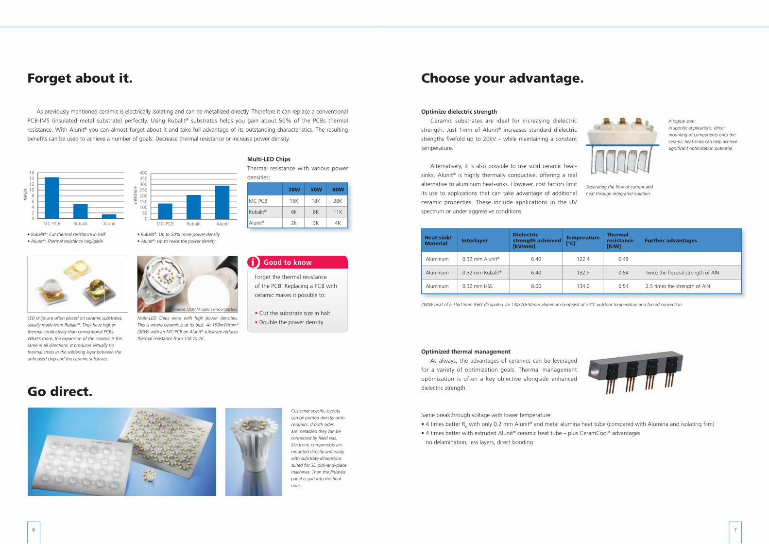
Multi-LED Chips work with high power densities.
This is where ceramic is at its best. At 150mW/mm²
(38W) with an MC-PCB an Alunit® substrate reduces
thermal resistance from 15K to 2K.
LED chips are often placed on ceramic substrates,
usually made from Rubalit®. They have higher
thermal conductivity than conventional PCBs.
What’s more, the expansion of the ceramic is the
same in all directions. It produces virtually no
thermal stress in the soldering layer between the
unhoused chip and the ceramic substrate.
Multi-LED Chips
Thermal resistance with various power
densities:
• Rubalit®: Cut thermal resistance in half
• Alunit®: Thermal resistance negligible
16141210
86420
MC-PCB Rubalit Alunit
400350300250200150100
500
MC-PCB Rubalit Alunit
• Rubalit®: Up to 50% more power density
• Alunit®: Up to twice the power density
Customer specifi c layouts
can be printed directly onto
ceramics. If both sides
are metalized they can be
connected by fi lled vias.
Electronic components are
mounted directly and easily
with substrate dimensions
suited for 3D pick-and–place
machines. Then the fi nished
panel is split into the fi nal
units.
Go direct.
38W 50W 80W
MC PCB 15K 18K 28K
Rubalit® 6k 8K 11K
Alunit® 2k 3K 4K
Choose your advantage.
Optimize dielectric strength
Ceramic substrates are ideal for increasing dielectric
strength. Just 1mm of Alunit® increases standard dielectric
strengths fivefold up to 20kV – while maintaining a constant
temperature.
Alternatively, it is also possible to use solid ceramic heat-
sinks. Alunit® is highly thermally conductive, offering a real
alternative to aluminum heat-sinks. However, cost factors limit
its use to applications that can take advantage of additional
ceramic properties. These include applications in the UV
spectrum or under aggressive conditions.
Optimized thermal management
As always, the advantages of ceramics can be leveraged
for a variety of optimization goals. Thermal management
optimization is often a key objective alongside enhanced
dielectric strength.
Heat-sink/ Material Interlayer
Dielectric strength achieved [kV/mm]
Temperature [°C]
Thermal resistance [K/W]
Further advantages
Aluminum 0.32 mm Alunit® 6.40 122.4 0.49
Aluminum 0.32 mm Rubalit® 6.40 132.9 0.54 Twice the flexural strength of AlN
Aluminum 0.32 mm HSS 8.00 134.0 0.54 2.5 times the strength of AlN
A logical step:
In specifi c applications, direct
mounting of components onto the
ceramic heat-sinks can help achieve
signifi cant optimization potential.
200W heat of a 15x15mm IGBT dissipated via 130x70x50mm aluminum heat-sink at 25°C outdoor temperature and forced convection.
Same breakthrough voltage with lower temperature:
• 4 times better Rtt with only 0.2 mm Alunit® and metal alumina heat tube (compared with Alumina and isolating film)
• 4 times better with extruded Alunit® ceramic heat tube – plus CeramCool® advantages:
no delamination, less layers, direct bonding
strengths fivefold up to 20kV – while maintaining a constant
is highly thermally conductive, offering a real
Separating the fl ow of current and
heat through integrated isolation.
iForget the thermal resistance
of the PCB. Replacing a PCB with
ceramic makes it possible to:
• Cut the substrate size in half
• Double the power density
Good to know
mW
/mm
2
Kel
vin
Source: OSRAM Opto Semiconductors
8 9
heat slugT
R (total thermal resistance)tt
ambienceT
Rtt for valid system comparison
The thermal resistance of LEDs (die to heat slug pad) and
heat-sinks is available from the manufacturer. But there is little
focus on group 3 and its significant influence on the total
thermal performance. Adding all thermal resistances but the
LED (group 1) yields the total thermal resistance, or Rtt. The Rtt
allows a real comparison of heat management concepts! Rtt = (T_heatslug – T_ambience) / heat emission LED
Rtt indicates the total thermal resistance from the LED’s heat slug to the surrounding.
The comprehensive factor simplifies the comparisons of cooling systems and their efficiency.
Use it all.
Ceramic is the material of choice for a variety of optimi-
zation steps. Simply using it as a thin substrate offers enor-
mous advantages. But the true optimization potential of this
material can only be fully leveraged with CeramCool®.
The CeramCool® Concept
CeramCool® is an effective combination of circuit board
and heat-sink for the reliable cooling of thermally sensitive
components and circuits. It enables the direct and permanent
connection of components. Also, ceramic is electrically iso-
lating per se and can provide bonding surfaces by using
metalization pads. Customer-specific conductor track struc-
tures can be provided, if required even in three-dimensional
form. The ceramic heat-sink becomes a module substrate that
can be densely populated with components – ideal for
efficient packaging. It quickly dissipates the generated heat
without creating any barriers. How does it work?
Two optimization blocks
Group 1 is the LED itself, mainly with a die and a heat
slug, a copper part, which connects the die with the bottom
of the LED. Thermally, the ideal solution is direct bonding of
Three groups build a thermal management system and are examined
for optimization potential. Why not eliminate block 3?
CeramCool® System with only two blocks for long term stability
and high reliability.
solder
Group 3
LEDGroup 1
Group 2
LED Group 1
Group 2
Standard Concept CeramCool
PCBelectrical isolation & mechanical mount
glue
aluminiumHeat-Sink
solder &circuit board
CeramCoolceramic Heat-Sink electrical isolationmechanical mount
the die to the heat-sink itself. More and more dies are bonded
onto ceramic substrates profiting from ceramic characteristics.
Group 2 is the heat-sink, transmitting energy from a heat
source to a heat drain (usually air with free or forced con-
vection). The less aesthetic the material, the higher the need
to conceal it. The more it is concealed the less efficient the
cooling will become. Alternatively, more suitable, aesthetically
appealing materials can be used, exposed directly to air or
water and become part of the visible product design.
Group 3 is situated between group one and two. It pro-
vides mechanical connection, electrical isolation and thermal
transmittance. This seems contradictory since most materials
with good thermal conductivity also conduct electricity. By the
same token almost every electrical isolation material translates
into a thermal barrier. The best compromise is soldering the
LED to a conventional PCB, which is then glued on the metal
heat-sink. This helps preserve the PCB’s original function as
a circuit board. Although PCBs exist with various thermal
conductivities they remain an obstacle to thermal transfer.
solder
Group 3
LEDGroup 1
Group 2
LED Group 1
Group 2
Standard Concept CeramCool
PCBelectrical isolation & mechanical mount
glue
aluminiumHeat-Sink
solder &circuit board
CeramCoolceramic Heat-Sink electrical isolationmechanical mount
Validation and proof of concept.
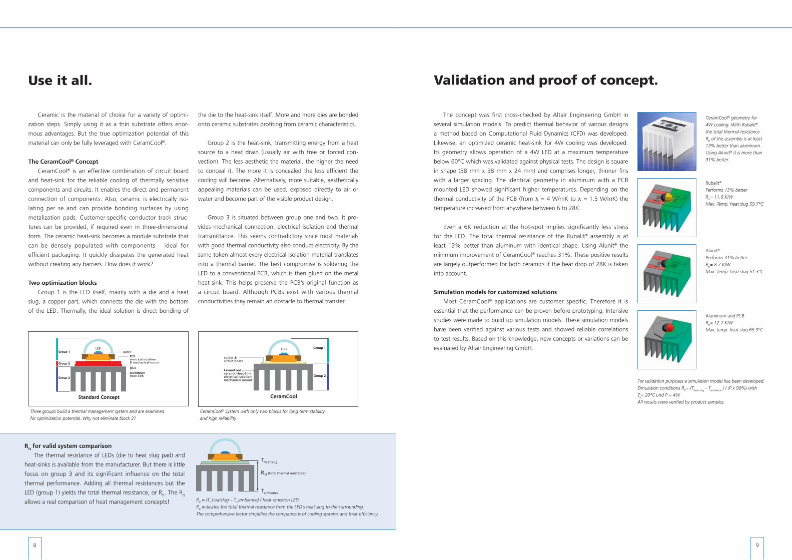
The concept was first cross-checked by Altair Engineering GmbH in
several simulation models. To predict thermal behavior of various designs
a method based on Computational Fluid Dynamics (CFD) was developed.
Likewise, an optimized ceramic heat-sink for 4W cooling was developed.
Its geometry allows operation of a 4W LED at a maximum temperature
below 60°C which was validated against physical tests. The design is square
in shape (38 mm x 38 mm x 24 mm) and comprises longer, thinner fins
with a larger spacing. The identical geometry in aluminum with a PCB
mounted LED showed significant higher temperatures. Depending on the
thermal conductivity of the PCB (from = 4 W/mK to = 1.5 W/mK) the
temperature increased from anywhere between 6 to 28K.
Even a 6K reduction at the hot-spot implies significantly less stress
for the LED. The total thermal resistance of the Rubalit® assembly is at
least 13% better than aluminum with identical shape. Using Alunit® the
minimum improvement of CeramCool® reaches 31%. These positive results
are largely outperformed for both ceramics if the heat drop of 28K is taken
into account.
Simulation models for customized solutions
Most CeramCool® applications are customer specific. Therefore it is
essential that the performance can be proven before prototyping. Intensive
studies were made to build up simulation models. These simulation models
have been verified against various tests and showed reliable correlations
to test results. Based on this knowledge, new concepts or variations can be
evaluated by Altair Engineering GmbH.
CeramCool® geometry for
4W cooling. With Rubalit®
the total thermal resistance
Rtt of the assembly is at least
13% better than aluminum.
Using Alunit® it is more than
31% better.
Rubalit®
Performs 13% better
Rtt= 11.0 K/W
Max. Temp. heat slug 59.7°C
Alunit®
Performs 31% better
Rtt= 8.7 K/W
Max. Temp. heat slug 51.3°C
Aluminum and PCB
Rtt= 12.7 K/W
Max. temp. heat slug 65.9°C
For validation purposes a simulation model has been developed.
Simulation conditions Rtt= (T
heat slug - T
ambience ) / (P x 90%) with
Ta= 20°C und P = 4W.
All results were verified by product samples.

10 11
For extreme power densities.
Any cooling capacity
Air cooling reaches its limits at very high
power densities. This is where liquid cooling is
best suited. Ceramics eliminate problems caused
by corrosion. The concept follows the same goal
as that of air cooled heat-sinks: the shortest
(thermal) distance between heat source and heat
drain. CeramCool® makes it possible for cooling
water to be just 1mm away from the heat slug!
No other concept can offer this benefit in com-
bination with the durable nature of ceramics.
The result: CeramCool® liquid cooling allows
almost any cooling capacity.
Shapes and design variations
Design and number of cooling channels
according to specific requirements. Even simple
linear pipe systems deliver amazing cooling
capacities, but complex spiral structures are also
possible to ensure especially homogeneous
cooling.
The compact CeramCool® Box is made for
homogeneous and efficient cooling of packing
densities up to 100W/cm². With an edge length
of 16 x 40 x 40 mm it provides a total cooling
capacity of 1600W at 90°C. This translates into
a temperature delta of 60K to the coolant. It can
be scaled in any direction; a nut helps simplify
CeramCool® Liquid Cooling for UV-LEDs
UV-LEDs put traditional PCBs under an inordinate amount
of stress. This leads to premature LED aging in particular due
to improper cooling and downtime because of delamination.
A directly metalized ceramic CeramCool® with chip on board
mounting of LEDs delivers decisive advantages. Test series
demonstrate efficient cooling, which counteracts degradation
of LEDs for longer than average periods. A comparison
between the simulation and measurement series shows that
UV radiant flux and aging
200%175%150%125%100%
75%50%25%
0%200 400 600 800 1000 1200
Symmetrical spiral
condensers with multi-level
flow paths ensure even
cooling all the way to the
exterior.
Chip on heat-sink guarantees
optimized cooling.
Free choice of cooling media
Heat-sink corrosion alters the surfaces in
the cooling channel and modifies the flow
behavior of the cooling agent (e.g. velocity).
Since ceramic is inert, it provides an additional
advantage: the freedom to choose the type of
cooling media you want.
a much lower rise in LED current is required to compensate for
the aging effect as originally assumed.
The difference in intensity of the UV-LEDs within the
CeramCool® Liquid Cooling module is negligible, making it
possible to produce uniform, large-surface modular systems.
Ceramic’s inertness and above all its resistance to UV rays
significantly enhance system life.
Even simple geometries
deliver high cooling
capacities. The extruded
ceramic heat-sink cools
MOSFETs with simultaneously
high dielectric strength.
Twall: 30°C
Tmax = 52.9°C (Alunit)
Tmax = 118.8°C (Rubalit)
Twall: 50°C
Tmax = 72.9°C (Alunit)
Tmax = 138.7°C (Rubalit)
The extruded, linear CeramCool® cools 4x150W MOSFETs.
As always, the parameters can be optimized to achieve a
number of different goals. It makes sense to use a ceramic
substrate mounted onto conventional aluminum heat-sinks in
applications whose sole objective lies in optimizing dielectric
strength. Thermal optimization while maintaining the dielectric
strength results in four times the cooling capacity when using
a liquid-cooled Alunit® assembly (21x21x150 mm) versus an
aluminum heat-sink with a conventional PCB. Benefits offered
by CeramCool® – including long systems life, the elimination
of delamination risk, etc. – justify the use of solid ceramic
solutions.
An additional linear CeramCool® version is designed to cool
high-power LEDs. Depending on the requirements Rubalit®
or Alunit® may be used for the same geometries. On a length
of 120mm this makes it possible to cool 290W or 640W,
respectively.
mounting. The number of cooling water connec-
tions is limited to just one inlet and outlet. This
helps simplify systems integration.
The ceramic walls are 2mm thick on the out-
side and 1mm thick on the inside. The material
selected is Alunit® ceramic, whose thermal con-
ductivity of > 170 W/mK when combined with
a direct Ag/Pt metalization for chip on heat-sink
mounting guarantees outstanding thermal con-
ductivity from the heat slug to the cooling media.
UV
rad
iant
flux
aging / h
with aging compensation
without aging compensation
1312
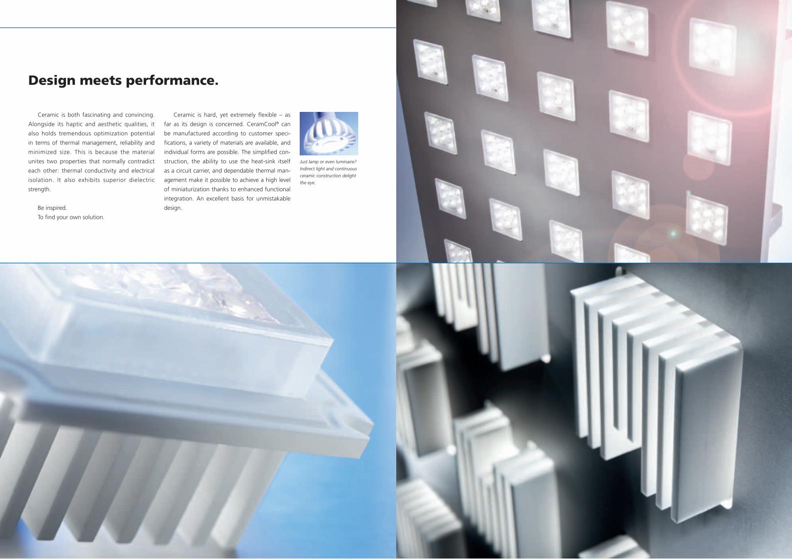
Design meets performance.
Ceramic is hard, yet extremely flexible – as
far as its design is concerned. CeramCool® can
be manufactured according to customer speci-
fications, a variety of materials are available, and
individual forms are possible. The simplified con-
struction, the ability to use the heat-sink itself
as a circuit carrier, and dependable thermal man-
agement make it possible to achieve a high level
of miniaturization thanks to enhanced functional
integration. An excellent basis for unmistakable
design.
Just lamp or even luminaire?
Indirect light and continuous
ceramic construction delight
the eye.
Ceramic is both fascinating and convincing.
Alongside its haptic and aesthetic qualities, it
also holds tremendous optimization potential
in terms of thermal management, reliability and
minimized size. This is because the material
unites two properties that normally contradict
each other: thermal conductivity and electrical
isolation. It also exhibits superior dielectric
strength.
Be inspired.
To find your own solution.
14 15
i Metalization
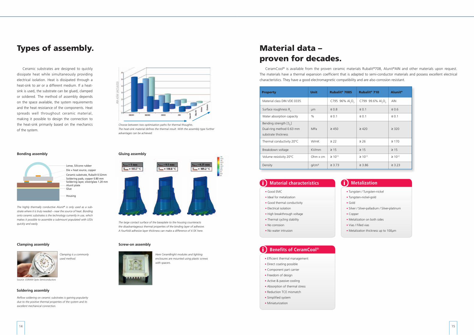
Material data – proven for decades.
CeramCool® is available from the proven ceramic materials Rubalit®708, Alunit®AIN and other materials upon request.
The materials have a thermal expansion coefficient that is adapted to semi-conductor materials and possess excellent electrical
characteristics. They have a good electromagnetic compatibility and are also corrosion resistant.
Property Unit Rubalit® 708S Rubalit® 710 Alunit®
Material class DIN VDE 0335 C795 96% Al2O3 C799 99.6% Al2O3 AlN
Surface roughness R a µm ≤ 0.8 ≤ 0.1 ≤ 0.6
Water absorption capacity % ≤ 0.1 ≤ 0.1 ≤ 0.1
Bending strength [ S0 ]
Dual-ring method 0.63 mm
substrate thickness
MPa ≥ 450 ≥ 420 ≥ 320
Thermal conductivity 20°C W/mK ≥ 22 ≥ 26 ≥ 170
Breakdown voltage KV/mm ≥ 15 ≥ 15 ≥ 15
Volume resistivity 20°C Ohm x cm ≥ 1013 ≥ 1013 ≥ 1012
Density g/cm³ ≥ 3.73 ≥ 3.86 ≥ 3.23
• Tungsten / Tungsten-nickel
• Tungsten-nickel-gold
• Gold
• Silver / Silver-palladium / Silver-platinum
• Copper
• Metalization on both sides
• Vias / Filled vias
• Metalization thickness up to 100µm
Types of assembly.
Ceramic substrates are designed to quickly
dissipate heat while simultaneously providing
electrical isolation. Heat is dissipated through a
heat-sink to air or a different medium. If a heat-
sink is used, the substrate can be glued, clamped
or soldered. The method of assembly depends
on the space available, the system requirements
and the heat resistance of the components. Heat
spreads well throughout ceramic material,
making it possible to design the connection to
the heat-sink primarily based on the mechanics
of the system.
The highly thermally conductive Alunit® is only used as a sub-
strate where it is truly needed – near the source of heat. Bonding
onto ceramic substrates is the technology currently in use, which
makes it possible to assemble a submount populated with LEDs
quickly and easily.
Here CeramBright modules and lighting
enclosures are mounted using plastic screws
with spacers.
Screw-on assembly
Bonding assembly
Choose between two optimisation paths for thermal thoughts.
The heat-sink material defi nes the thermal result. With the assembly type further
advantages can be achieved.
Clamping is a commonly
used method.
Clamping assembly
Source: OSRAM Opto Semiconductors
The large contact surface of the baseplate to the housing counteracts
the disadvantageous thermal properties of the binding layer of adhesive.
A fourfold adhesive layer thickness can make a difference of 4.5K here.
Gluing assembly
Die = heat source, copper
Lense, Silicone rubber
Ceramic substrate, Rubalit 0.52mm
Glue
Housing
Alunit plateSoldering layer, silver/glass 1.20 mmSoldering pads, copper 0.80 mm
Refl ow soldering on ceramic substrates is gaining popularity
due to the positive thermal properties of the system and its
excellent mechanical connection.
Soldering assembly
i Material characteristics
• Good EMC
• Ideal for metalization
• Good thermal conductivity
• Electrical isolation
• High breakthrough voltage
• Thermal cycling stability
• No corrosion
• No water intrusion
• Efficient thermal management
• Direct coating possible
• Component part carrier
• Freedom of design
• Active & passive cooling
• Absorption of thermal stress
• Reduction TCE mismatch
• Simplified system
• Miniaturization
i Benefits of CeramCool®
Rth
K/W
(AC
ULE
D)
T H E C E R A M I C E X P E R T S EL12
0031
• E
N •
500
• 1
307
• at
io (3
397)
• P
rinte
d in
Ger
man
y
Indexes and parameters for ceramic substances: In order to profile ceramic substances certain parameters are indicated. The crystalline nature of these substances, statistical fluctuations in the composition of the substances and in the factors that impact on the production processes indicate that the figures quoted are typically mean values and hence the substance parameters quoted in this brochure are only standard, recommended or guide values that might differ given dissimilar dimensions and production processes.
CeramTec GmbH Electronic Applications Division
CeramTec-Weg 195615 Marktredwitz
GermanyPhone: +49 9231 69 - 387
Fax: +49 9231 [email protected]
www.ceramcool.com


