CE 312 Structural Analysis and Design Sessional-I … Analysis and Design Sessional-I (CE312) manual...
110
CE 312 Structural Analysis and Design Sessional-I (Lab Manual) Department of Civil Engineering Ahsanullah University of Science and Technology December, 2017
Transcript of CE 312 Structural Analysis and Design Sessional-I … Analysis and Design Sessional-I (CE312) manual...

CE 312 Structural Analysis and Design Sessional-I
(Lab Manual)
Department of Civil Engineering Ahsanullah University of Science and Technology
December, 2017
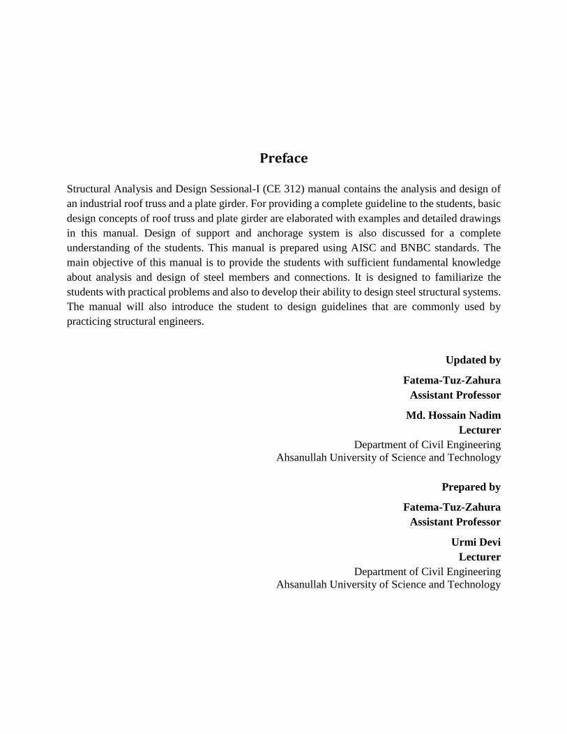
Preface
Structural Analysis and Design Sessional-I (CE 312) manual contains the analysis and design of
an industrial roof truss and a plate girder. For providing a complete guideline to the students, basic
design concepts of roof truss and plate girder are elaborated with examples and detailed drawings
in this manual. Design of support and anchorage system is also discussed for a complete
understanding of the students. This manual is prepared using AISC and BNBC standards. The
main objective of this manual is to provide the students with sufficient fundamental knowledge
about analysis and design of steel members and connections. It is designed to familiarize the
students with practical problems and also to develop their ability to design steel structural systems.
The manual will also introduce the student to design guidelines that are commonly used by
practicing structural engineers.
Updated by
Fatema-Tuz-Zahura
Assistant Professor
Md. Hossain Nadim
Lecturer
Department of Civil Engineering
Ahsanullah University of Science and Technology
Prepared by
Fatema-Tuz-Zahura
Assistant Professor
Urmi Devi
Lecturer
Department of Civil Engineering
Ahsanullah University of Science and Technology

INDEX
Page no.
Part 1 Steel Fundamentals 1-7
Part 2 Design of an Industrial Steel Roof Truss 8-53
2.1 Introduction 8
2.2 Assumptions 8
2.3 Advantages 8
2.4 Types of truss 9-11
2.5 Roof Truss Example Data 12-13
2.6 Design of Purlin for Dead Load 13-22
2.6.1 Analysis and Design of Purlin for Dead Load 13-17
2.6.2 Analysis and Design of Purlin for Dead Load
plus Wind Load
18-22
2.7 Analysis and Design of Sagrods 22
2.8 Analysis of the Truss 22-28
2.9 Design of Truss Members 29-36
2.9.1 Design of Top Chord 29-30
2.9.2 Design of Bottom Chord 30-31
2.9.3 Design of Verticals 31-33
2.9.4 Design of Diagonals / Web Members 33-36
2.10 Design of Bracing Systems 36-38
2.10.1 Vertical Bracing 36
2.10.2 Top Chord Bracing 36-37
2.10.3 Bottom Chord Bracing 37-38
2.11 Design of Truss Joints (Welded Connections) 38-51
2.12 Design of Anchorage and Support: 51-53
Part 3 Design of Steel Plate Girder 54-85
3.1 Introduction 54
3.2 Advantages and Disadvantages of Plate girder 55
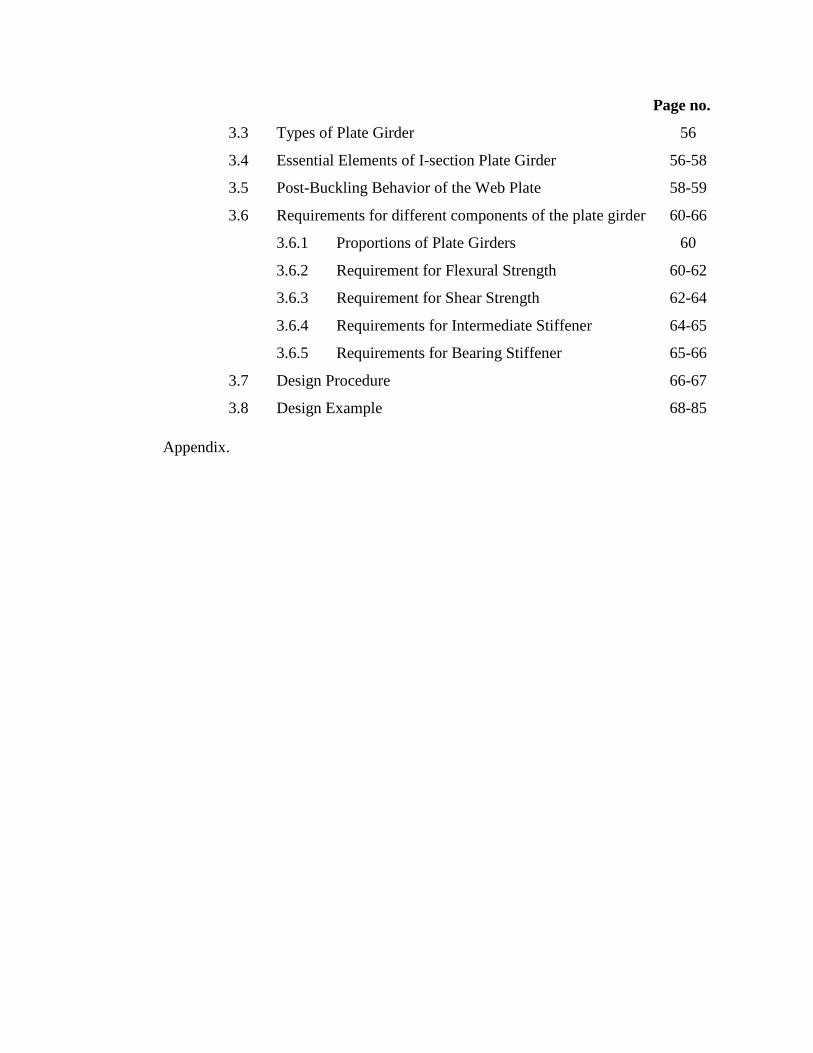
Page no.
3.3 Types of Plate Girder 56
3.4 Essential Elements of I-section Plate Girder 56-58
3.5 Post-Buckling Behavior of the Web Plate 58-59
3.6 Requirements for different components of the plate girder 60-66
3.6.1 Proportions of Plate Girders 60
3.6.2 Requirement for Flexural Strength 60-62
3.6.3 Requirement for Shear Strength 62-64
3.6.4 Requirements for Intermediate Stiffener 64-65
3.6.5 Requirements for Bearing Stiffener 65-66
3.7 Design Procedure 66-67
3.8 Design Example 68-85
Appendix.
1 | P a g e
Part 1: Steel Fundamentals
Steel Structure: a structure which is made from organized combination of structural steel
members designed to carry loads and provide adequate rigidity. Steel structures involve sub-
structure or members in a building made from structural steel
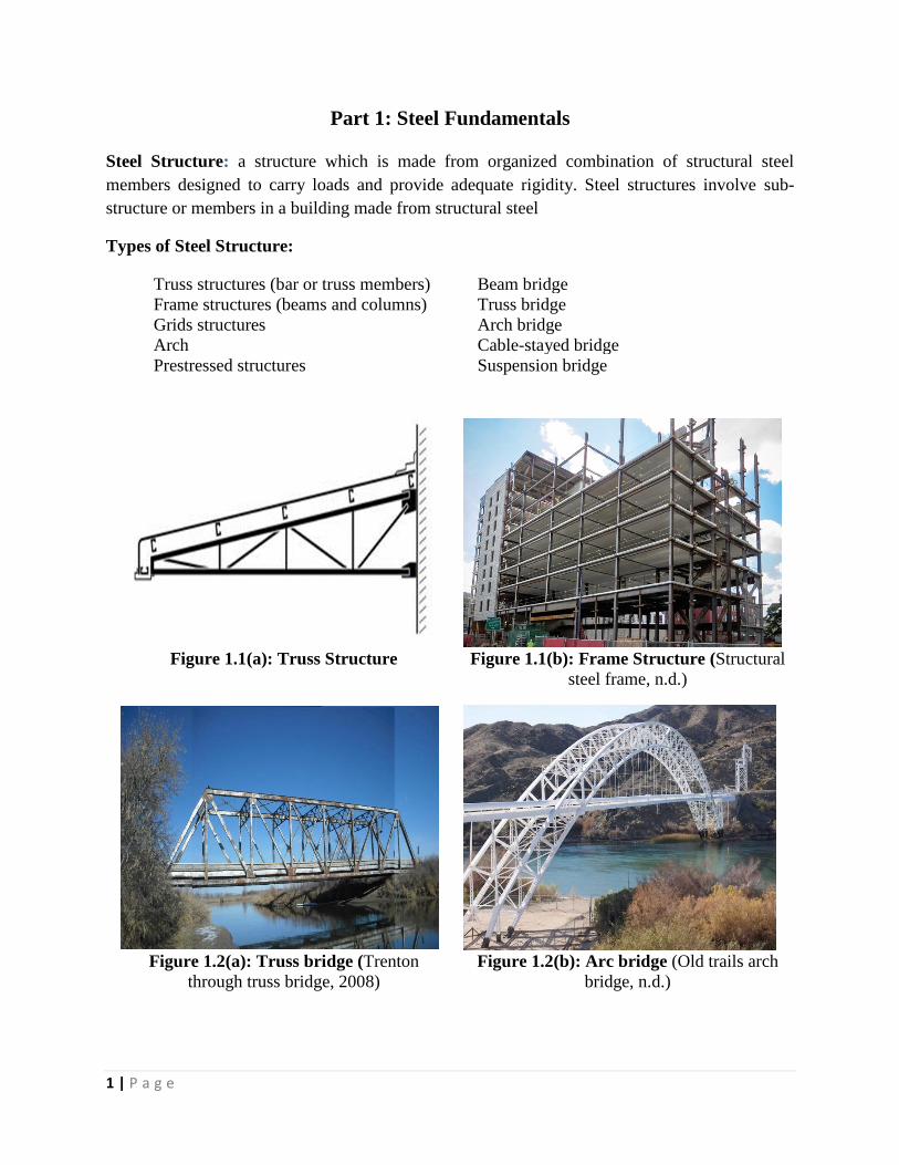
Types of Steel Structure:
Truss structures (bar or truss members) Beam bridge
Frame structures (beams and columns) Truss bridge
Grids structures Arch bridge
Arch Cable-stayed bridge
Prestressed structures Suspension bridge
Figure 1.1(a): Truss Structure
Figure 1.1(b): Frame Structure (Structural
steel frame, n.d.)
Figure 1.2(a): Truss bridge (Trenton
through truss bridge, 2008)
Figure 1.2(b): Arc bridge (Old trails arch
bridge, n.d.)

2 | P a g e
Advantages of Steel:
a) High strength per unit weight especially when compared to concrete. This can reduce the
size of the elements in the structure and increase the living space.
b) Uniformity: that reduces the effect of time on steel as compared to concrete that changes
throughout its life.
c) Elasticity: steel is elastic, that is it follows Hook's Law as long as its stresses do not exceed
its yielding stress. So, steel behaves closer to design assumptions as compared to other
materials
d) Moment of inertia of steel is accurately calculated where as that of concrete changes as the
cracks move up towards the neutral axis and past it.
e) Durability and performance: If properly maintained the properties of steel do not change
appreciably with time.
f) Ductility: since steel is a ductile material, it can undergo extensive deformations after which
increased stresses are required for failure to occur. This is a property that can save lives.
g) It is easier to add to a steel structure than it is to a concrete structure mainly due to
connections.
h) It is faster to build a steel structure than it is a concrete structure due to its lightness compared
to concrete, it requires no curing time, and the members are easily connected (bolted,
welded, and riveted).
i) Reliability: Steel Structures are very reliable. The reason for this reliability is uniformity and
consistency in properties, and better-quality control because of factory manufacture.
j) Possible Reuse: Steel sections can be reused after a structure has been disassembled. Steel
also has very good scrap value.
Disadvantages of Steel:
a) Maintenance cost: steel requires maintenance against corrosion. However, this cost may be
eliminated by using atmospheric corrosion-resistant steel such as A242 and A588.
b) Fireproofing costs: steel will not ignite. However, at 1200°F steel has very little strength. Its
temperature should not exceed 800°F beyond which its strength is reduced quickly.
c) Buckling: can occur when long slender steel members are exposed to compressive loads. To
avoid buckling, a larger cross-section is needed which will increase cost.
d) Fatigue: is caused by a large number of repetitive tensile stress variations. This can reduce
the strength and ductility of the steel causing a sudden failure.
e) Aesthetics: A considerable amount of money has to be spent on steel structure to improve
their appearance.

3 | P a g e
Steel Design Specifications:
The specifications of most interest to the structural steel designer are those published by the
following organizations.
• American Institute of Steel Construction (AISC)
• American Association of State Highway and Transportation Officials (AASHTO)
• American Railway Engineering and Maintenance-of-Way Association (AREMA)
• American Iron and Steel Institute (AISI)
Design Methodology
The design of a structural member entails the selection of a cross section that will safely and
economically resist the applied loads. The fundamental requirement of structural design is that the
required strength not exceed the available strength; that is,
Required strength ≤ available strength
Design for strength is performed according to the provisions for load and resistance factor design
(LRFD) or to the provisions for allowable strength design (ASD).
Allowable Strength Design (ASD):
In this method a member is selected that has cross‐sectional properties such as area and moment of
inertia that are large enough to prevent the maximum applied axial force, shear, or bending moment
from exceeding an allowable, or permissible, value. This allowable value is obtained by dividing
the nominal or theoretical, strength by a factor of safety.
This can be expressed as,
𝐴𝑙𝑙𝑜𝑤𝑎𝑏𝑙𝑒 strength = 𝑁𝑜𝑚𝑖𝑛𝑎𝑙 𝑠𝑡𝑟𝑒𝑛𝑔𝑡ℎ
𝑆𝑎𝑓𝑒𝑡𝑦 𝑓𝑎𝑐𝑡𝑜𝑟
Load and resistance factor design (LRFD)
In this method load factors are applied to the service loads, and a member is selected that will have
enough strength to resist the factored loads. In addition, the theoretical strength of the member is
reduced by the application of a resistance factor. The criterion that must be satisfied in the selection
of a member is
𝐹𝑎𝑐𝑡𝑜𝑟𝑒𝑑 𝑙𝑜𝑎𝑑 ≤ 𝑓𝑎𝑐𝑡𝑜𝑟𝑒𝑑 𝑠𝑡𝑟𝑒𝑛𝑔𝑡ℎ
In this expression, the factored load is actually the sum of all service loads to be resisted by the
member, each multiplied by its own load factor. For example, dead loads will have load factors that
are different from those for live loads. The factored strength is the theoretical strength multiplied
by a resistance factor.
𝛴(𝑙𝑜𝑎𝑑𝑠 × 𝑙𝑜𝑎𝑑 𝑓𝑎𝑐𝑡𝑜𝑟𝑠 ) ≤ resistance ×resistance factor

4 | P a g e
Structural Steel:
Steel Grade: Different grades of structural steel are identified by the designation assigned them by
the American Society for Testing and Materials (ASTM).
Property A36 A572 Gr. 50 A992
Yield point, min. 36 ksi 50 ksi 50 ksi
Tensile strength, min. 58 to 80 ksi 65 ksi 65 ksi
Yield to tensile ratio, max. — — 0.85
Classification of structural steel:
• Compact: Section reaches its full strength (yield) before local buckling occurs. Strength of
section is governed by material strength
• Non-compact: Only a portion of the cross-section reaches its full strength (yield) before
local buckling occurs
• Slender: Cross-section does not yield before local buckling occurs. Strength is governed by
buckling
AISC classifies cross-sectional shapes as compact, noncompact, or slender, depending on the values
of the width-to-thickness ratios. Classification are given in AISC Table B4.1
Notation:
𝜆 = width / thickness ratio
𝜆𝑝 = upper limit for compact category
𝜆𝑟 = upper limit for non-compact category
If 𝜆 ≤𝜆𝑝 and the flange is continuously attached to the web, the shape is compact
If 𝜆𝑝 ≤ 𝜆 ≤ 𝜆𝑟 , the shape is non-compact
If 𝜆 > 𝜆𝑟, the shape is slender (These values are discussed later in the manual)
The category is based on the worst width-to-thickness ratio of the cross section. For example, if the
web is compact and the flange is noncompact, the shape is classified as noncompact.
Types of Structural Steel:
Hot Rolled Steel: Hot rolling is a mill process which involves rolling the steel at a high temperature
(typically at a temperature over 1700° F), which is above the steel’s recrystallization temperature.
When steel is above the recrystallization temperature, it can be shaped and formed easily, and the
steel can be made in much larger sizes. Hot rolled steel is typically cheaper than cold rolled steel
due to the fact that it is often manufactured without any delays in the process, and therefore the
reheating of the steel is not required (as it is with cold rolled). When the steel cools off it will shrink

5 | P a g e
slightly thus giving less control on the size and shape of the finished product when compared to
cold rolled.
Cold Rolled Steel: Cold rolled steel is essentially hot rolled steel that has had further processing.
The steel is processed further in cold reduction mills, where the material is cooled (at room
temperature) followed by annealing and/or tempers rolling. This process will produce steel with
closer dimensional tolerances and a wider range of surface finishes. The term Cold Rolled is
mistakenly used on all products, when actually the product name refers to the rolling of flat rolled
sheet and coil products.
Built-up Section: Built -up members are obtained by connecting two or more plates or shapes which
then act as a single member. Such members may be made necessary by requirement of the area,
which can’t be provided by a single rolled shape, or by the requirement of rigidity because for the
same area, much greater moment of inertia can be obtained with built-up sections compared to single
rolled shapes, or by the requirement of suitable connection, where the width or depth of member
necessary for proper connection can’t be obtained in a standard rolled section.
Standard rolled Shapes (Structural steel shapes, n.d.)
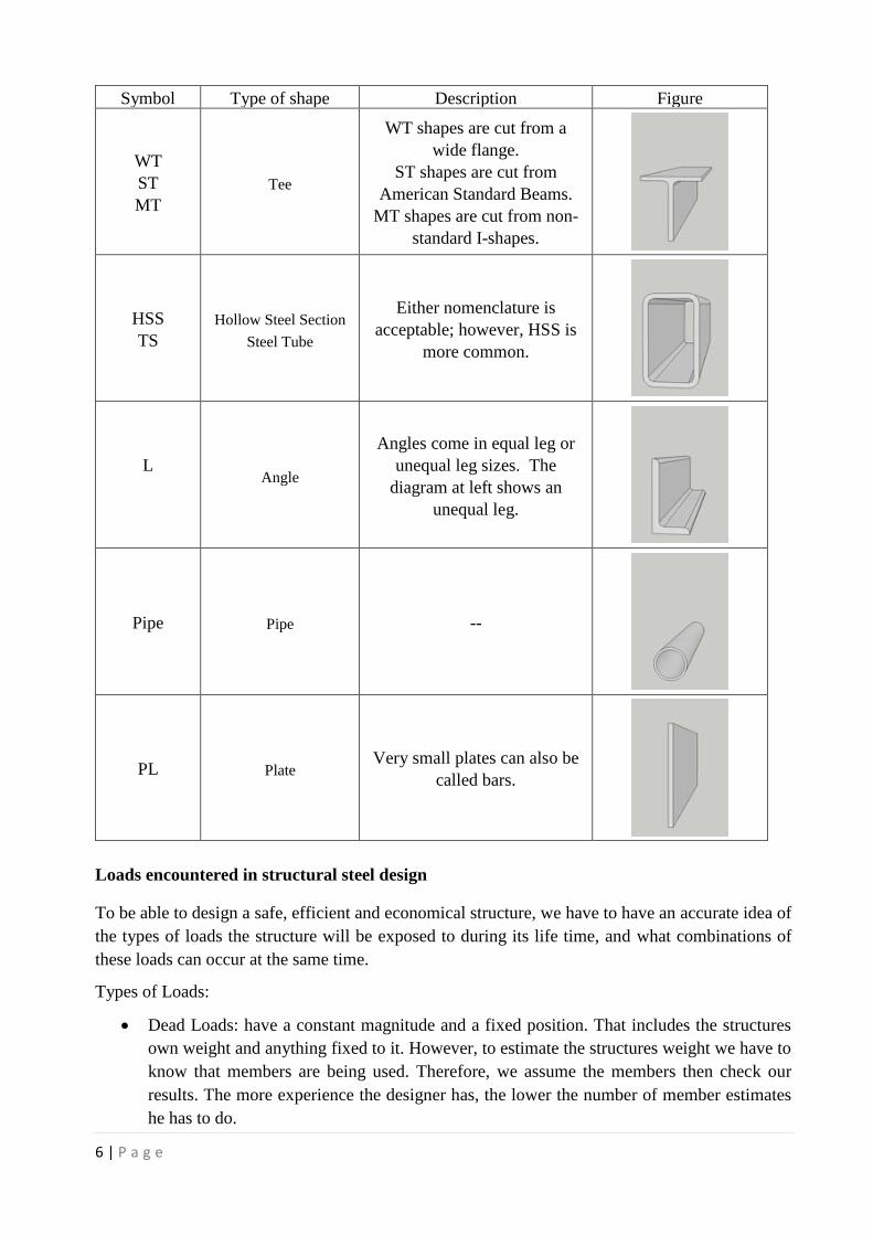
Symbol Type of shape Description Figure
W Wide Flange
Flange surfaces are parallel;
flange thickness is not
necessarily equal to the web
thickness.
HP Bearing Pile
Flange surfaces are parallel;
flange and web have equal
thicknesses.
S American Standard
Beam
The inner flange surface is
sloped.
C Channel Standard AISC flanges have
sloped inner flange surfaces.
6 | P a g e
Symbol Type of shape Description Figure
WT
ST
MT
Tee
WT shapes are cut from a
wide flange.
ST shapes are cut from
American Standard Beams.
MT shapes are cut from non-
standard I-shapes.
HSS
TS
Hollow Steel Section
Steel Tube
Either nomenclature is
acceptable; however, HSS is
more common.
L
Angle
Angles come in equal leg or
unequal leg sizes. The
diagram at left shows an
unequal leg.
Pipe Pipe --
PL Plate Very small plates can also be
called bars.
Loads encountered in structural steel design
To be able to design a safe, efficient and economical structure, we have to have an accurate idea of
the types of loads the structure will be exposed to during its life time, and what combinations of
these loads can occur at the same time.
Types of Loads:
• Dead Loads: have a constant magnitude and a fixed position. That includes the structures
own weight and anything fixed to it. However, to estimate the structures weight we have to
know that members are being used. Therefore, we assume the members then check our
results. The more experience the designer has, the lower the number of member estimates
he has to do.
7 | P a g e
• Live loads: change in magnitude and position. If it is not a dead load then it is a live load.
Live loads are of 2 types: Moving loads that move by their own power (cars and trucks).
Movable loads (furniture). Few examples of live loads are:
i. floor loads
ii. Snow and ice
iii. Rain especially on flat roofs because ponding develops causing deflections.
iv. Traffic loads for bridges.
v. Impact loads: such as falling objects or sudden car braking.
vi. Lateral loads: such as wind, which changes with height, geographic location,
surrounding structures
vii. Earthquakes are another example of impact loads.
viii. longitudinal loads: such as sudden stopping of trains or trucks on bridges.
ix. Other live loads: soil pressure on walls or foundations, water on dams,
explosions, thermal forces due to temperature changes…...etc.

8 | P a g e
Part 2: Design of an Industrial Steel Roof Truss
2.1 Introduction
A truss is a structure composed of slender members joined together at their end points. Planar trusses
lie in a single plane. Typically, the joint connections are formed by bolting or welding the end
members together to a common plate, called a gusset plate. The basic building block of a truss is a
triangle. Large trusses are constructed by attaching several triangles together. A new triangle can be
added truss by adding two members and a joint. A truss constructed in this fashion is known as a
simple truss.
2.2 Assumptions:
The main assumptions made in the analysis of truss are:
• Truss members are connected together at their ends only.
• Trusses are connected together by frictionless pins.
• The truss structure is loaded only at the joints.
2.3 Advantages of Truss:
Quick Installation
The primary advantage of a truss is that it can be installed quickly and cost-effectively, even without
heavy equipment to lift it into place. Most trusses are factory-built, and delivered to the job site as
a complete set for the structure to be built. A truss is traditionally leveraged to the top of the wall,
and then slid into position and pivoted upright before being fastened in place.
Increased Span
The unique properties of a triangular object allow trusses to span across longer distances. Where a
square-sided roof would tend to shift or twist, a triangular one maintains its shape, preventing shift
and sag. As a further advantage, the entire set of trusses combined becomes stable and able to
support many times the weight of a non-reinforced straight roof.
Load Distribution
The shape of a triangle allows all of the weight applied to the sides (or legs) to be redistributed down
and away from the center. In trusses, this transfers the entire weight of the roof to the outer walls,
and has the advantage of allowing the interior walls to be built arbitrarily, or even moved or omitted.
Accessibility
Since the bottom rail of a truss is typically the ceiling of the rooms below, the triangular spaces of
the trusses themselves form accessible paths for the installation of electric and other utility
applications. The central void of a truss system is generally the attic of a home, with the slope of
the roof forming the legs of the triangle.
9 | P a g e
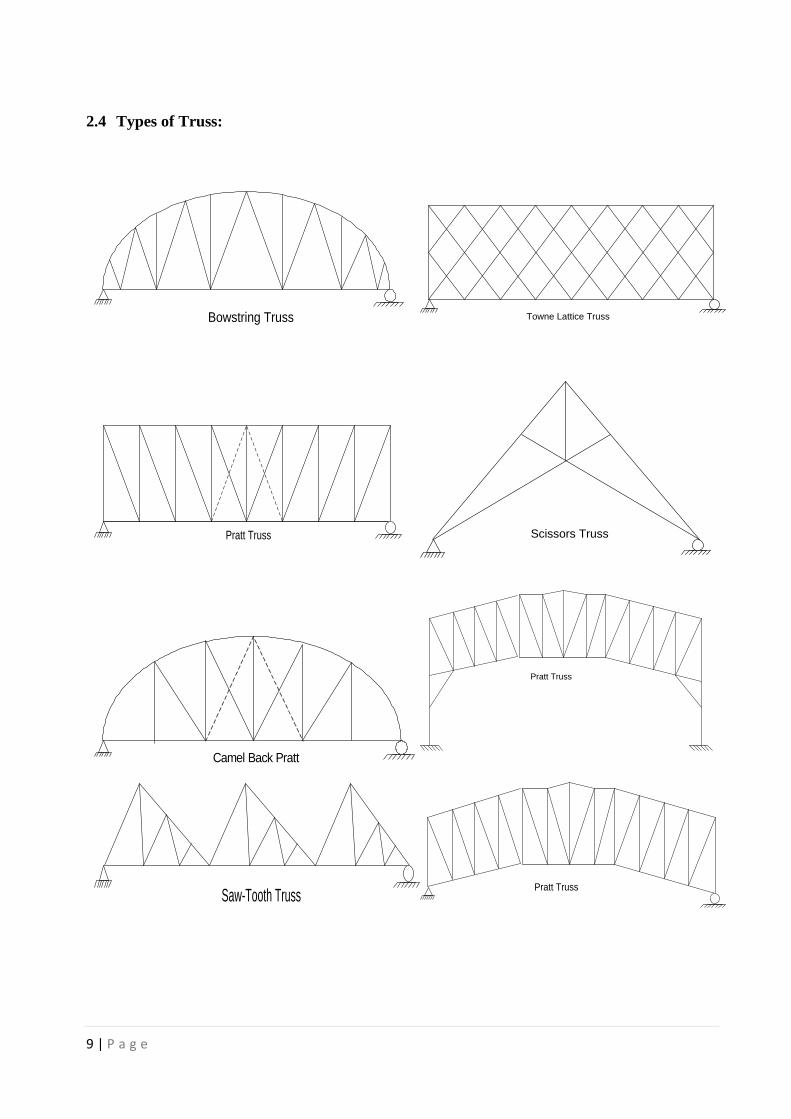
2.4 Types of Truss:
Towne Lattice Truss
Pratt Truss Scissors Truss
Pratt Truss
Saw-Tooth Truss
Pratt Truss
Bowstring Truss
Camel Back Pratt
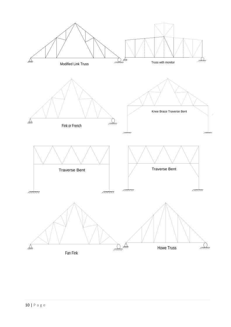
10 | P a g e
Modified Link Truss Truss with monitor
Fink or French
Knee Brace Traverse Bent
Traverse Bent
Traverse Bent
Fan Fink
Howe Truss

11 | P a g e
Howe Truss
Warren Truss
Howe (Pitch) Truss
Warren Truss
Figure 2.1: Different types of truss
Figure 2.2: Bracing System of truss
Figure 2.3: Building Plan

12 | P a g e
2.5 Roof Truss Design
Design a Pratt type roof truss from the following data:
Design Data:
Span = 40 feet
Span-to-rise ratio (pitch) = 4:1
Rise = 10 feet
Slope (θ) = tan-1(10/20) = 26.56510 (degree)
Bay distance (truss-to-truss distance) = 25 feet.
Location: Dhaka, Basic wind speed = 210 Km/h.
Exposure category: Exposure A
Truss is supported on brick wall of height = 12 feet.
Design Loads:
(1) Dead load:
Self-weight of truss = 60 lb per ft. horizontal span of truss.
Sag rod + bracing = 1 psf. (approximately known)
C.G.I. sheet roofing = 2 psf. (known)
Purlin (self-weight) = 1.5 psf. (assumed)
(2) Wind load = according to BNBC 1993 (Bangladesh National Building Code 1993).
(3) Snow load = not applicable for our country.
Design Method:
Design method followed here is AISC/ASD
Steel to be used: A36 (Yield stress (Fy = 36 ksi)
Electrode to be used: E60XX (electrode material tensile strength (FEXX) = 60 ksi)

13 | P a g e
Figure 2.4: Pratt type Roof Truss
Figure 2.5: Truss notations (member numbering): Pratt truss (Roof)
2.6 Analysis and Design of Purlins:
• Analysis and design of purlin for dead load
• Analysis and design of purlin for dead load plus wind load
2.6.1 Analysis and Design of Purlin for Dead Load:
Purlins are nothing but beams. They span between the adjacent trusses, i.e. the spacing of the trusses
is the span of purlins. Purlins are placed at top chord joint. Since the principal axes of the purlin are
inclined, the dead load causes bi-axial bending in the purlins. A component of dead load acts in the
negative Y direction and the other component acts in the X direction. For the loads acting along Y-
axis, the purlin acts as a simply supported beam (see figure 7) of span 25 feet (bay distance). Due
to the presence of sagrods, the midspan deflection is restrained in the X direction. As a result the

14 | P a g e
purlin act as a continuous beam (see figure 8) for bending in the plane of the roof surface (X
direction).
The dead load coming on the purlin is from the roofing material and the self-weight of the purlin
itself. Weights of the sagrods are so small compared to the other loads that we can safely neglect it.
Calculation of total dead load on purlin:
C.G.I sheet roofing = 2 psf (known)
Self-weight of purlins = 1.5 psf (assumed but will be checked later)
Sagrod weight = negligable
Total dead load = 3.50 psf
Uniformly distributed load (UDL) on purlin, WDL= 3.50 psf × purlin spacing
= 3.50 psf × 7.453 ft.
= 26.0855 lb. per feet
Component of WDL in X direction, WDLx = WDL ×sinθ
= 26.0855 × sin26.5650
= 11.666 lb. per feet
Component of WDL in Y direction, WDLy = WDL ×cosθ
= 26.0855 × cos26.5650
= 23.332 lb. per feet
Purlin span = 25 feet for loading in Y direction (loading perpendicular to the plane of roof
surface).
Purlin span = 12.5 feet + 12.5 feet for loading X direction (loading in the plane of roof surface)
Figure 2.6: Bi-axial loading on the purlin
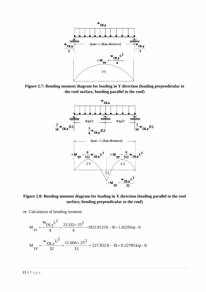
15 | P a g e
Figure 2.7: Bending moment diagram for loading in Y direction (loading perpendicular to
the roof surface, bending parallel to the roof)
Figure 2.8: Bending moment diagram for loading in X direction (loading parallel to the roof
surface, bending perpendicular to the roof)
Calculation of bending moment:
ft-kip 1.8228 lbft 1822.8125 8
22523.332
8
2LDLy
W
xxM
ft-kip 0.22785 lbft 227.85232
22511.666
32
2LDLx
w
yyM

16 | P a g e
xxM = moment about X axis (moment in plane of roof surface)
yyM = moment about Y axis (moment perpendicular to the plane of roof surface)
In the design of purlin, we assume that the purlin has adequate lateral bracing due to the presence
of roofing and sag-rod so that pure bending will govern the design. As our first trial, we select the
smallest available American Standard Channel C 3×4.1. From AISC manual
Channel xxS (inch3)
yyS (inch3)
C 3×4.1 1.10 0.202
xx
S & yy
S = Section modulus about X axis & Y axis respectively.
Allowable bending stress, y
0.66Fb
F
For A36 steel, y
0.66Fb
F = 0.66 × 36 ksi = 23.76 ksi
Calculation of actual bending stress:
Bending stress developed on purlin section,
yyI
)x
(cyy
M
xxI
)y
(cxx
M
f
Maximum bending stress developed on purlin section,
yyI
)x
(cyy
M
xxI
)y
(cxx
M
f
)
x/c
yy(I
yyM
)y
/cxx
(I
xxM
f
yyS
yyM
xxS
xxM
f
ksi 33.4210.202
120.22785
1.10
121.8228f
Check of bending stress:
Actual bending stress (f = 33.421 ksi) > allowable bending stress (Fb = 23.76 ksi)
Thus, section is not OK. Select a higher section.

17 | P a g e
Table 2.1: Criteria for adequacy of the section
Criteria Comments
If, b
Ff Section is OK
If, b
Ff Section is not OK; select a higher
section
If, b
Ff Section is OK but not economical;
select a lower section
Table 2.2: Purlin section selection for dead load
Section xxS (inch3)
yyS (inch3)
Actual
bending
stress (f) in
ksi
Allowable
bending stress
)b
(F in ksi Comments
C 3×4.1 1.10 0.202 33.421 23.76 not OK
C 3×5 1.24 0.233 29.374 23.76 not OK
C 3×6 1.38 0.268 26.053 23.76 not OK
C 4×5.4 1.93 0.283 20.995 23.76 OK
C 4×7.25 2.29 0.343 17.523 23.76 OK but not
economical
C 5×6.7 3.00 0.378 14.525 23.76 OK but not
economical
C 5×9 3.56 0.450 12.220 23.76 OK but not
economical
Check self-weight of purlin:
For C 4×5.4 channel, self-weight is 5.4 lb/ft which is equivalent to ft 7.4535
lb/ft 5.4 = 0.7245 psf
(distributed load over the roof surface) which is smaller than previously/initially assumed purlin
self-weight 1.50 psf. So, the purlin C 4×5.4 is adequate for resisting bending moment (i.e.
bending stress) & its self-weight is well-below the previously/initially assumed value.
Select a C 4×5.4 section for purlin (mind it, this selection is done only for dead load).

18 | P a g e
2.6.2 Analysis and Design of Purlin for Dead Load plus Wind Load:
Wind Load Calculation (according to BNBC 1993):
Figure 2.9: Plan and elevation of roof truss
Different parameters for wind load calculation:
Truss location: Dhaka
Vb= Basic wind speed in km/h = 210 km/h
B = Horizontal dimension of the building, in meters measured normal to wind direction = bay
distance (truss-to-truss spacing) = 25 feet = 7.6219 meter.
L = Horizontal dimension of the building, in meters measured parallel to wind direction = span
of truss = 40 feet = 12.1951 meter.
H = average/mean height of the roof in meters = 17 feet = 5.1829 meter.
z = Height above the ground in meters
θ = Angle of the plane of roof from horizontal, degrees = 26.56510 (degree)
Cc= Velocity-to-pressure conversion co-efficient = 61047.2
CI = Structure importance co-efficient (a factor that accounts for the degree of hazard to hazard
to human life and damage to property) = 1.00 for standard occupancy structures
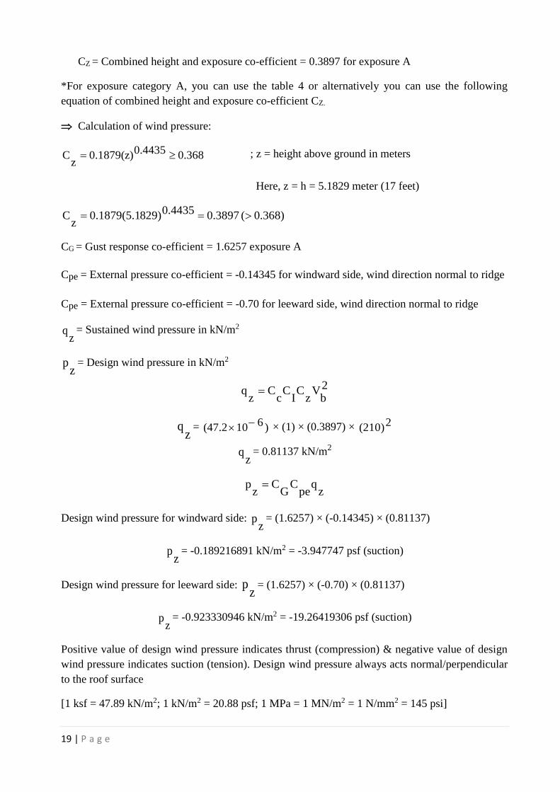
19 | P a g e
CZ = Combined height and exposure co-efficient = 0.3897 for exposure A
*For exposure category A, you can use the table 4 or alternatively you can use the following
equation of combined height and exposure co-efficient CZ.
Calculation of wind pressure:
368.00.44350.1879(z)z
C ; z = height above ground in meters
Here, z = h = 5.1829 meter (17 feet)
0.368)( 0.38970.4435829)0.1879(5.1z
C
CG = Gust response co-efficient = 1.6257 exposure A
Cpe = External pressure co-efficient = -0.14345 for windward side, wind direction normal to ridge
Cpe = External pressure co-efficient = -0.70 for leeward side, wind direction normal to ridge
zq = Sustained wind pressure in kN/m2
zp = Design wind pressure in kN/m2
2b
Vz
CI
Cc
Cz
q
zq = )610(47.2 × (1) × (0.3897) × 2(210)
zq = 0.81137 kN/m2
zq
peC
GC
zp
Design wind pressure for windward side: z
p = (1.6257) × (-0.14345) × (0.81137)
zp = -0.189216891 kN/m2 = -3.947747 psf (suction)
Design wind pressure for leeward side: z
p = (1.6257) × (-0.70) × (0.81137)
zp = -0.923330946 kN/m2 = -19.26419306 psf (suction)
Positive value of design wind pressure indicates thrust (compression) & negative value of design
wind pressure indicates suction (tension). Design wind pressure always acts normal/perpendicular
to the roof surface
[1 ksf = 47.89 kN/m2; 1 kN/m2 = 20.88 psf; 1 MPa = 1 MN/m2 = 1 N/mm2 = 145 psi]

20 | P a g e
Figure 2.10: Wind direction and pressure distribution on windward side &leeward side
Calculation of UDL on purlin:
UDL on purlin on windward side = (design wind pressure on the windward side × purlin spacing)
= -3.947747 psf × 7.4535 feet = - 29.4247 lb/ft
UDL on purlin on leeward side = (design wind pressure on the leeward side × purlin spacing)
= -19.26419 psf × 7.4535 feet = - 143.5857 lb/ft
Since wind load acts perpendicular to the roof surface, these loads will be combined with the Y
component of the dead load (WDLy) to get the resultant load. It is clear from the above that the
leeward side will govern since its magnitude is higher.
Resultant load in Y direction, z
pDLy
wy
w
(i.e. resultant load perpendicular to roof surface) = +23.332 lb/ft – 143.5856 lb/ft
y
w = – 120.2536 lb/ft
lbft 9394.8125lbft 8
225120.2536
8
2(L)y
w
xxM
xxM = -9.3948 kip-ft
Load )DLx
(w in X direction (in plane of roof) remains the same, so moment about Y axis remains
the same
yyM = 0.22785 kip-ft
-19.2642 psf -3.9477 psf
-19.2642 psf -3.9477
psf

21 | P a g e
Allowable bending stress, y
0.66Fb
F
For A36 steel, y
0.66Fb
F = 0.66 × 36 ksi = 23.76 ksi
Bending stress developed on purlin section,
yyI
)x
(cyy
M
xxI
)y
(cxx
M
f
Maximum bending stress developed on purlin section,
yyI
)x
(cyy
M
xxI
)y
(cxx
M
f
)
x/c
yy(I
yyM
)y
/cxx
(I
xxM
f
yyS
yyM
xxS
xxM
f
For previously selected channel section (for dead load) C 4×5.4 (xx
S = 1.10 inch3 & yy
S = 0.202
inch3)
ksi 68.0750.202
120.22785
1.10
129.3948f
> 23.76 ksi (not OK)
Select channel C 6×13 (xx
S = 5.80 inch3 & yy
S = 0.642 inch3)
ksi 23.6960.642
120.22785
5.80
129.3948f
< 23.76 ksi (OK)
Check self-weight of purlin:
For C 6×13 channel, self-weight is 13 lb/ft which is equivalent to ft 7.4535
lb/ft 13 = 1.744 psf
(distributed load over the roof surface) which is greater than previously/initially assumed purlin
self-weight 1.50 psf. Although the purlin C 6×13 is adequate for resisting bending moment (i.e.
bending stress) but its self-weight is high. So, not OK & select another section.
Select channel C 7×9.8 (xx
S = 6.08 inch3 & yy
S = 0.625 inch3)
ksi 22.9170.625
120.22785
6.08
129.3948f
< 23.76 ksi (OK)

22 | P a g e
Check self-weight of purlin:
For C 7×9.8 channel, self-weight is 9.8 lb/ft which is equivalent to ft 7.4535
lb/ft 9 = 1.3148 psf
(distributed load over the roof surface) which is smaller than previously/initially assumed purlin
self-weight 1.50 psf. So, the purlin C 7×9.8 is adequate for resisting bending moment (i.e.
bending stress) & its self-weight is well-below the previously/initially assumed value.
Loading Selected channel
section
Check bending
stress Check self-weight
Dead load only C 4×5.4 OK OK
Dead load + wind
load C 7×9.8 OK OK
Finally selected channel for purlins: C 7×9.8
2.7 Analysis and Design of Sagrods:
Sagrods prevent the purlin to deflect in the plane of the roof surface at midspan. Thus according to
figure 8 the tensile force in the sagrods is equivalent to the midspan reaction.
Sagrod force, feet 25plf 11.6678
5L
DLxw
8
5 F
F = 182.28125 lb. = 0.18228125 kip. (tensile)
A round bar of 3/8 inch diameter will be adequate (this is the minimum size). Assuming that the
bolts threads will reduce the effective diameter by 1/16 inch, the net cross-sectional area will be
2inch 90.0766990321/163/8π/4 . If allowable stress in tension is y
0.6Ft
F . For A 36
steel, ksi 21.60ksi 360.6y
0.6Ft
F , then this rod will be able to carry a load of 21.60 ksi
× 0.076699039 inch2 = 1.656699 kip, which is well above the actual load (=0.18228125 kip).
2.8 Analysis of the Truss: (Dead load calculation & wind load calculation)
Figure 2.11: Truss notations (member numbering): Pratt truss (Roof)
23 | P a g e
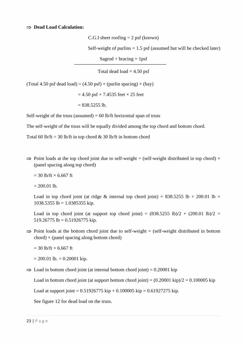
Dead Load Calculation:
C.G.I sheet roofing = 2 psf (known)
Self-weight of purlins = 1.5 psf (assumed but will be checked later)
Sagrod + bracing = 1psf
Total dead load = 4.50 psf
(Total 4.50 psf dead load) = (4.50 psf) × (purlin spacing) × (bay)
= 4.50 psf × 7.4535 feet × 25 feet
= 838.5255 lb.
Self-weight of the truss (assumed) = 60 lb/ft horizontal span of truss
The self-weight of the truss will be equally divided among the top chord and bottom chord.
Total 60 lb/ft = 30 lb/ft in top chord & 30 lb/ft in bottom chord
Point loads at the top chord joint due to self-weight = (self-weight distributed in top chord) ×
(panel spacing along top chord)
= 30 lb/ft × 6.667 ft
= 200.01 lb.
Load in top chord joint (at ridge & internal top chord joint) = 838.5255 lb + 200.01 lb =
1038.5355 lb = 1.0385355 kip.
Load in top chord joint (at support top chord joint) = (838.5255 lb)/2 + (200.01 lb)/2 =
519.26775 lb = 0.51926775 kip.
Point loads at the bottom chord joint due to self-weight = (self-weight distributed in bottom
chord) × (panel spacing along bottom chord)
= 30 lb/ft × 6.667 ft
= 200.01 lb. = 0.20001 kip.
Load in bottom chord joint (at internal bottom chord joint) = 0.20001 kip
Load in bottom chord joint (at support bottom chord joint) = (0.20001 kip)/2 = 0.100005 kip
Load at support joint = 0.51926775 kip + 0.100005 kip = 0.61927275 kip.
See figure 12 for dead load on the truss.

24 | P a g e
Figure 2.12(a): Dead loads on the truss (self-weight distribution)
Figure 2.12(b): Dead loads on the truss (sagrod, bracing, purlin self-weight, roof weight
distribution)
22.361’
22.361’

25 | P a g e
Figure 2.13: Total dead loads on the truss
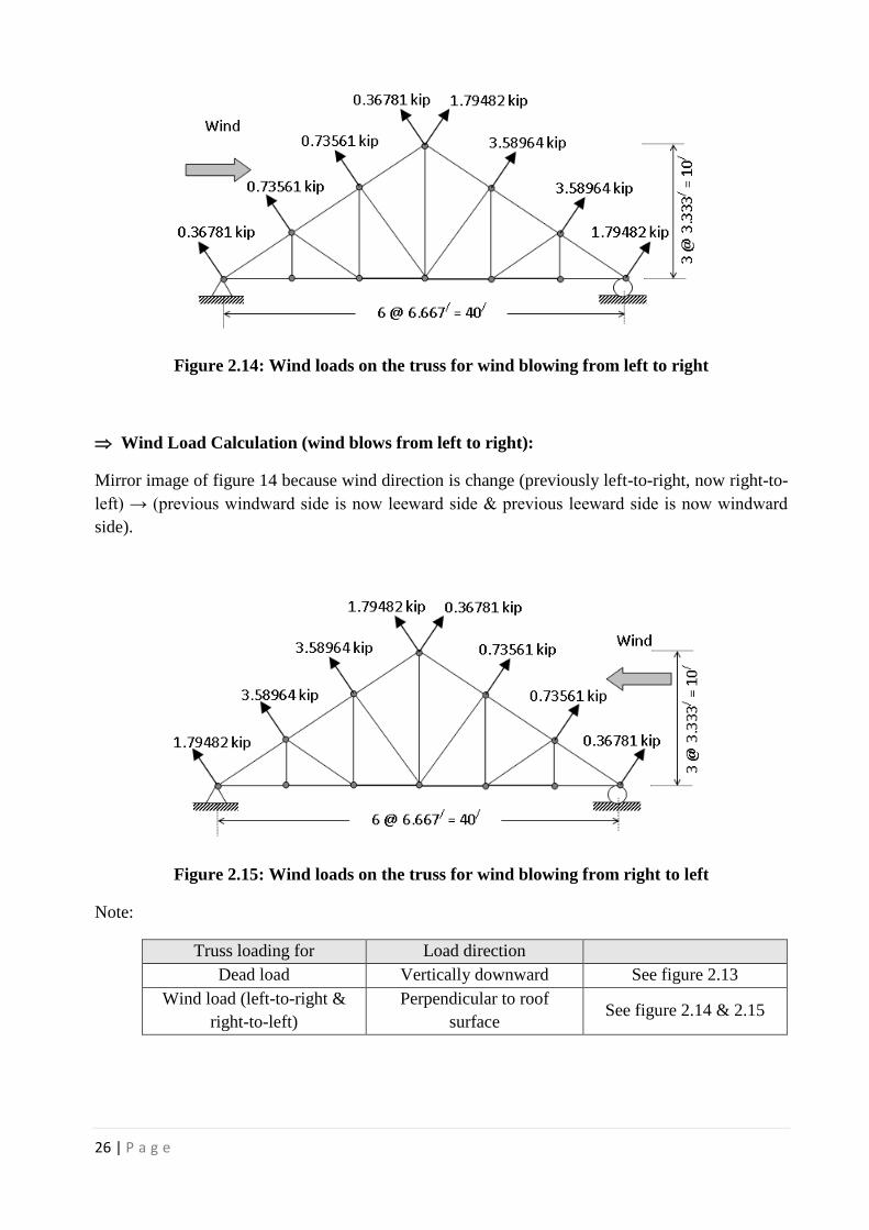
Wind Load Calculation (wind blows from left to right):
Design wind pressure on windward side = -3.947747 psf
Wind load on interior top chord joint windward side = (design wind pressure on windward side) ×
(purlin spacing) × (bay)
= -3.947747 psf × 7.4535 feet × 25 feet
= - 735.613 lb = - 0.73561 kip
Wind load on exterior & ridge top chord joint windward side = (design wind pressure on windward
side) × (purlin spacing/2) × (bay)
= (-3.947747 psf) × (7.4535/2 feet) × (25 feet)
= - 367.8065 lb = - 0.36781 kip
Design wind pressure on leeward side = -19.26419306 psf
Wind load on interior top chord joint leeward side = (design wind pressure on leeward side) × (purlin
spacing) × (bay)
= -19.26419306 psf × 7.4535 feet × 25 feet
= - 3589.641574 lb = - 3.58964 kip
Wind load on exterior & ridge top chord joint leeward side = (design wind pressure on leeward side)
× (purlin spacing/2) × (bay)
= (-19.26419306 psf) × (7.4535/2 feet) × (25 feet)
= - 1794.820787 lb = - 1.79482 kip
See figure 14 for wind loading on the truss (for wind blowing from left to right)
22.361’
26 | P a g e
Figure 2.14: Wind loads on the truss for wind blowing from left to right
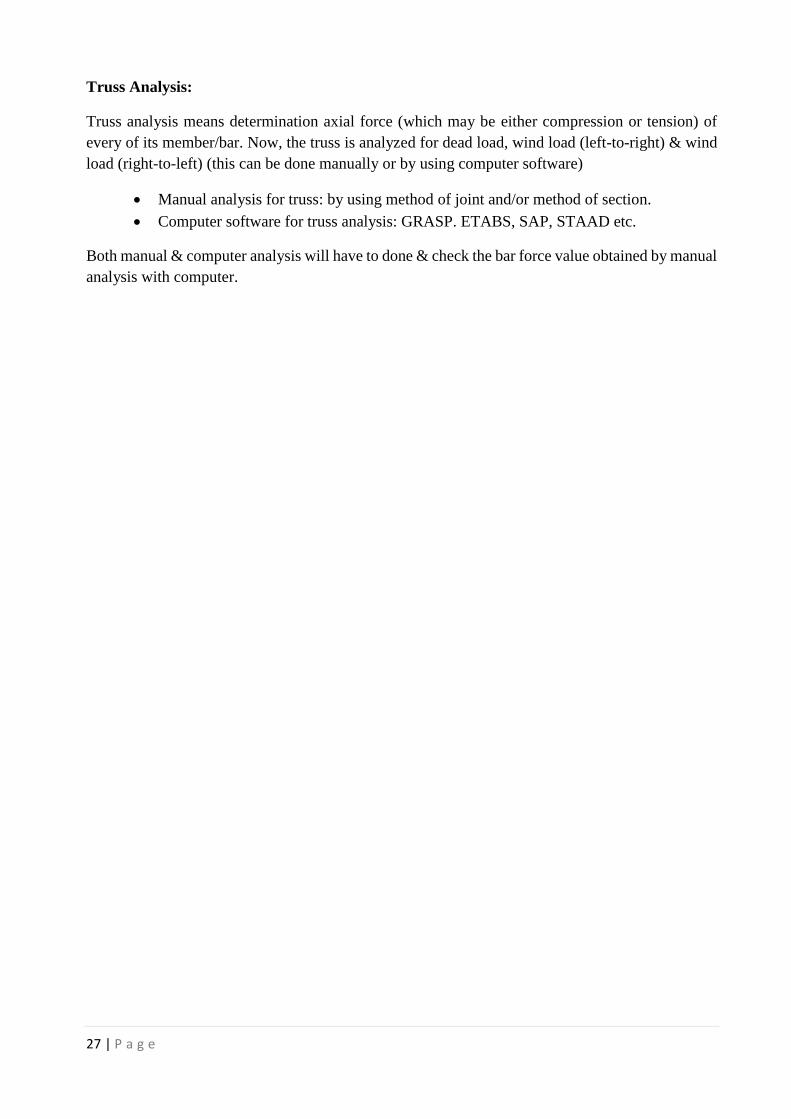
Wind Load Calculation (wind blows from left to right):
Mirror image of figure 14 because wind direction is change (previously left-to-right, now right-to-
left) → (previous windward side is now leeward side & previous leeward side is now windward
side).
Figure 2.15: Wind loads on the truss for wind blowing from right to left
Note:
Truss loading for Load direction
Dead load Vertically downward See figure 2.13
Wind load (left-to-right &
right-to-left)
Perpendicular to roof
surface See figure 2.14 & 2.15
27 | P a g e
Truss Analysis:
Truss analysis means determination axial force (which may be either compression or tension) of
every of its member/bar. Now, the truss is analyzed for dead load, wind load (left-to-right) & wind
load (right-to-left) (this can be done manually or by using computer software)
• Manual analysis for truss: by using method of joint and/or method of section.
• Computer software for truss analysis: GRASP. ETABS, SAP, STAAD etc.
Both manual & computer analysis will have to done & check the bar force value obtained by manual
analysis with computer.

28 | P a g e
Chart: Sample Design Force for truss members
Member Length
(ft)
Member Force (Kip) Dead
Load
only
(Kip)
Dead Load
+ Wind
(Left-to-
Right) (Kip)
Dead Load +
Wind
(Right-to-
Left) (Kip)
Design member forces
(Kip)
Dead
Load
(Kip)
Wind
(Left-to-
Right)
(Kip)+
Wind
(Right-to-
Left)
(Kip)
Tension
(Kip)
Compression
(Kip)
Top Chord
L0U1 7.4535 -15.73 15.995 33.829 -15.73 0.265 18.099 18.099 -15.73
U1U2 7.4535 -12.587 17.635 24.742 -12.587 5.048 12.155 12.155 -12.587
U2U3 7.4535 -9.438 19.255 15.631 -9.438 9.817 6.193 9.817 -9.438
U3U4 7.4535 -9.438 15.674 19.217 -9.438 6.236 9.779 9.779 -9.438
U4U5 7.4535 -12.587 24.704 17.597 -12.587 12.117 5.01 12.117 -12.587
U5L6 7.4535 -15.73 33.791 15.957 -15.73 18.061 0.227 18.061 -15.73
Bottom Chord
L0L1 6.6667 14.07 4.4 -46.737 14.07 18.47 -32.667 18.47 -32.667
L1L2 6.6667 14.07 4.4 -46.737 14.07 18.47 -32.667 18.47 -32.667
L2L3 6.6667 11.255 1.979 -33.185 11.255 13.234 -21.93 13.234 -21.93
L3L4 6.6667 11.255 -13.958 -17.189 11.255 -2.703 -5.934 11.255 -5.934
L4L5 6.6667 14.07 -27.511 -14.758 14.07 -13.441 -0.688 14.07 -13.441
L5L6 6.6667 14.07 -27.511 -14.758 14.07 -13.441 -0.688 14.07 -13.441
Verticals
U1L1 3.3333 0.275 0 0 0.275 0.275 0.275 0.275 0
U2L2 6.6667 1.683 1.21 -6.776 1.683 2.893 -5.093 2.893 -5.093
U3L3 10 5.902 -11.072 -11.132 5.902 -5.17 -5.23 5.902 -5.23
U4L4 6.6667 1.683 -6.777 1.216 1.683 -5.094 2.899 2.899 -5.094
U5L5 3.3333 0.275 0 0 0.275 0.275 0.275 0.275 0
Diagonals/Web
members
U1L2 7.4537 -3.149 -2.707 15.152 -3.149 -5.856 12.003 12.003 -5.858
U2L3 9.4286 -3.979 -3.436 19.179 -3.979 -7.415 15.2 15.2 -7.415
U4L3 9.4286 -3.979 19.094 -3.436 -3.979 15.115 -7.415 15.115 -7.415
U5L4 7.4535 -3.149 15.153 -2.718 -3.149 12.004 -5.867 12.004 -5.867

29 | P a g e
2.9 Design of Truss Members
2.9.1 Design of Top Chord:
From the design chart for truss member
For top chord (length, L = 7.4535 feet), maximum compressive force = − 15.73 kip &
maximum tensile force = + 18.099 kip.
Select an angle section L 3×2
12 ×
4
1; (cross sectional area, A = 1.31 inch2 & minimum radius
of gyration, z
r = 0.528 inch).
Check for Compression: Slenderness ratio, 0.528
124535.70.6
r
KL = 101.6386364
E = modulus of elasticity of steel = psi 61029 = 29000 ksi
yF = yield stress of the steel = 36 ksi (for A 36 steel)
yF
2Eπ
cC =
36
310292π
= 126.0992836
aF = allowable stress in compression (ksi)
cC
r
KL if
3
cC
KL/r
8
1
cC
KL/r
8
3
3
5
2
cC
KL/r
2
11
yF
aF
c
Cr
KL if
3
6126.099283
4101.638636
8
1
6126.099283
4101.638636
8
3
3
5
2
6126.099283
4101.638636
2
1163
aF
a
F = 12.769265 ksi
Allowable force in compression, a
P = a
F × A = 12.769265 ksi × 1.31 inch2
= 16.72773715 kip. (which is greater than design compressive force 15.73 kip).

30 | P a g e
The L 3×2
12 ×
4
1 section is OK for compressive force.
Check for Compression: Slenderness ratio, 0.528
124535.70.6
r
KL = 101.6386364 (which is
less than 300).
tF = allowable stress in tension (ksi)
t
F = y
0.6F = 0.6 × 36 ksi = 21.6 ksi
Allowable force in tension, t
P = t
F × A = 21.6 ksi × 1.31 inch2 = 28.296 kip. (which is greater
than design tensile force 18.099 kip). The L 3×2
12 ×
4
1 section is OK for tensile force.
Top chord 4
13
2
13 L
2.9.2 Design of Bottom Chord:
From the design chart for truss member
For bottom chord (length, L = 6.6667 feet), maximum compressive force = − 32.667 kip &
maximum tensile force = + 18.47 kip.
Select an angle section L 4×3×16
5; (cross sectional area, A = 2.09 inch2 & minimum radius of
gyration, z
r = 0.647 inch).
Check for Compression: Slenderness ratio, 0.528
126667.60.6
r
KL = 74.1885626
E = modulus of elasticity of steel = psi 61029 = 29000 ksi
yF = yield stress of the steel = 36 ksi (for A 36 steel)
yF
2Eπ
cC =
36
310292π
= 126.0992836
aF = allowable stress in compression (ksi)

31 | P a g e
cC
r
KL if
3
cC
KL/r
8
1
cC
KL/r
8
3
3
5
2
cC
KL/r
2
11
yF
aF
c
Cr
KL if
3
6126.099283
74.1885626
8
1
6126.099283
74.1885626
8
3
3
5
2
6126.099283
74.1885626
2
1163
aF
a
F = 15.988919 ksi
Allowable force in compression, a
P = a
F × A = 15.988919 ksi × 2.09 inch2 = 33.41684071
kip. (which is greater than design compressive force 32.667 kip). The L 4×3×16
5 section is
OK for compressive force.
Check for Compression: Slenderness ratio, 0.528
126667.60.6
r
KL = 74.1885626 (which is
less than 300).
tF = allowable stress in tension (ksi)
t
F = y
0.6F = 0.6 × 36 ksi = 21.6 ksi
Allowable force in tension, t
P = t
F × A = 21.6 ksi × 2.09 inch2 = 45.144 kip. (which is greater
than design tensile force 18.47 kip). The 16
534 L section is OK for tensile force.
Bottom chord 16
534 L
2.9.3 Design of Verticals:
From the design chart for truss member
For verticals 3
L3
U (length, L = 10 feet), maximum compressive force = − 5.23 kip &
maximum tensile force = + 5.902 kip.

32 | P a g e
Select an angle section L 2
12 ×
2
12 ×
16
3; (cross sectional area, A = 0.902 inch2 & minimum
radius of gyration, z
r = 0.495 inch).
Check for Compression: Slenderness ratio, 0.495
12100.6
r
KL = 145.4545455
E = modulus of elasticity of steel = psi 61029 = 29000 ksi
yF = yield stress of the steel = 36 ksi (for A 36 steel)
yF
2Eπ
cC =
36
310292π
= 126.0992836
aF = allowable stress in compression (ksi)
c
Cr
KL if
2
r
KL
149000
2
r
KL 23
E212π
aF
cC
r
KL if
25145.454545
149000
2
r
KL 23
E212π
aF
a
F = 7.042578121 ksi
Allowable force in compression, a
P = a
F × A = 7.042578121 ksi × 0.902 inch2 = 6.352405465
kip. (which is greater than design compressive force 5.23 kip). The L 3×2
12 ×
16
3 section is
OK for compressive force.
Check for Compression: Slenderness ratio, 0.495
12100.6
r
KL = 145.4545455 (which is
less than 300).
tF = allowable stress in tension (ksi)
t
F = y
0.6F = 0.6 × 36 ksi = 21.6 ksi
33 | P a g e
Allowable force in tension, t
P = t
F × A = 21.6 ksi × 0.905 inch2 = 19.548 kip. (which is greater
than design tensile force 5.902 kip). The L 3×2
12 ×
16
3 section is OK for tensile force.
Verticals 16
3
2
12
2
12 L
2.9.4 Design of Diagonals / Web Members:
From the design chart for truss member
For diagonals 3
L2
U /3
L4
U (length, L = 9.4286 feet), maximum compressive force = −
7.415 kip & maximum tensile force = + 15.2 kip.
Select an angle section L 3×2
12 ×
16
3; (cross sectional area, A = 0.996 inch2 & minimum radius
of gyration, z
r = 0.533 inch).
Check for Compression: Slenderness ratio, 0.533
124286.90.6
r
KL = 127.3657036
E = modulus of elasticity of steel = psi 61029 = 29000 ksi
yF = yield stress of the steel = 36 ksi (for A 36 steel)
yF
2Eπ
cC =
36
310292π
= 126.0992836
aF = allowable stress in compression (ksi)
c
Cr
KL if
2
r
KL
149000
2
r
KL 23
E212π
aF
cC
r
KL if
26127.365703
149000
2
r
KL 23
E212π
aF

34 | P a g e
a
F = 9.185044616 ksi
Allowable force in compression, a
P = a
F × A = 9.185044616 ksi × 0.996 inch2 = 9.148304438
kip. (which is greater than design compressive force 7.415 kip). The L 3×2
12 ×
16
3 section is
OK for compressive force.
Check for Compression: Slenderness ratio, 0.533
124286.90.6
r
KL = 127.3657036 (which is
less than 300).
tF = allowable stress in tension (ksi)
t
F = y
0.6F = 0.6 × 36 ksi = 21.6 ksi
Allowable force in tension, t
P = t
F × A = 21.6 ksi × 0.996 inch2 = 21.5136 kip. (which is
greater than design tensile force 15.2 kip). The L 3×2
12 ×
16
3 section is OK for tensile force.
Check whether the selected L 3×2
12 ×
16
3 section for diagonal member
3L
2U &
3L
4U is
OK or not for the other diagonal members 2
L1
U & 4
L5
U
For diagonals 2
L1
U /4
L5
U (length, L = 7.4537 feet), maximum compressive force = −
5.867 kip & maximum tensile force = + 12.004 kip.
Select an angle section L 3×2
12 ×
16
3; (cross sectional area, A = 0.996 inch2 & minimum radius
of gyration, z
r = 0.533 inch).
Check for Compression: Slenderness ratio, 0.533
124537.70.6
r
KL = 100.6878799
E = modulus of elasticity of steel = psi 61029 = 29000 ksi
yF = yield stress of the steel = 36 ksi (for A 36 steel)
yF
2Eπ
cC =
36
310292π
= 126.0992836

35 | P a g e
aF = allowable stress in compression (ksi)
cC
r
KL if
3
cC
KL/r
8
1
cC
KL/r
8
3
3
5
2
cC
KL/r
2
11
yF
aF
c
Cr
KL if
3
6126.099283
6127.365703
8
1
6126.099283
6127.365703
8
3
3
5
2
6126.099283
6127.365703
2
1163
aF
a
F = 9.2018618 ksi
Allowable force in compression, a
P = a
F × A = 9.2018618 ksi × 0.996 inch2 = 9.1650543 kip.
(which is greater than design compressive force 5.867 kip). The L 3×2
12 ×
16
3 section is OK
for compressive force.
Check for Compression: Slenderness ratio, 0.533
124286.90.6
r
KL = 127.3657036 (which is
less than 300).
tF = allowable stress in tension (ksi)
t
F = y
0.6F = 0.6 × 36 ksi = 21.6 ksi
Allowable force in tension, t
P = t
F × A = 21.6 ksi × 0.996 inch2 = 21.5136 kip. (which is
greater than design tensile force 12.004 kip). The L 3×2
12 ×
16
3 section is OK for tensile force.
Diagonals 16
3
2
123 L
36 | P a g e
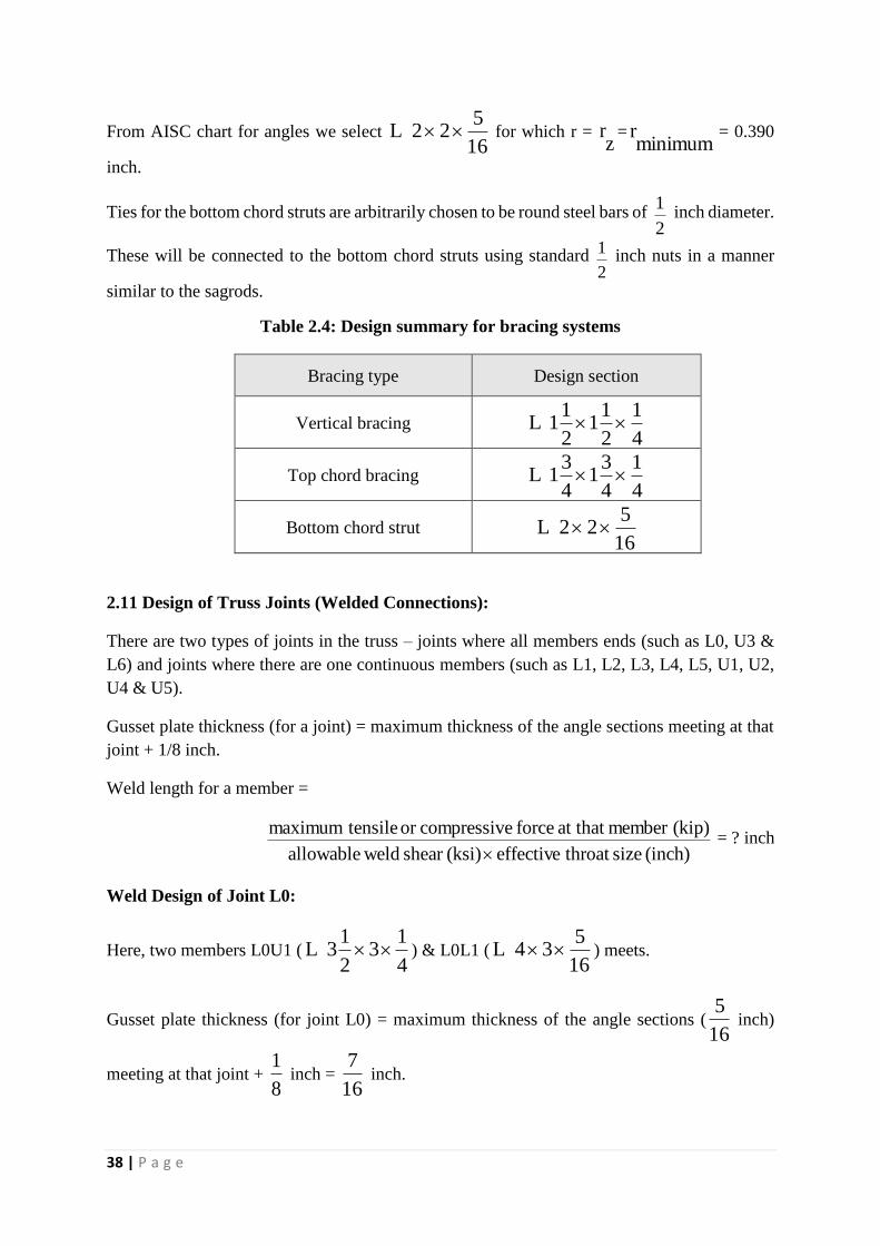
Table 2.3: Design summary for truss members
Member type Design section
Top chord 4
13
2
13 L
Bottom chord 16
534 L
Verticals 16
3
2
12
2
12 L
Web member / Diagonals 16
3
2
123 L
2.10 Design of Bracing Systems:
2.10.1 Vertical Bracing:
The members of the vertical bracing will be tied to each other at their crossing point. Therefore,
half of their length will be considered in determining slenderness ratio
r
KL . We will assume
that, effective length factor, K = 0.70. The length of member of the vertical bracing (L) =
2
225210 feet = 13.46291202 feet = 13.46291202 × 12 inch.
400
minimumr
KL
400
minimumr
1246291202.310.7
400
1246291202.310.7
minimumr
minimum
r > 0.2827211524 inch
From AISC chart for angles we select 4
1
2
11
2
11 L for which r =
zr =
minimumr = 0.292
inch.
2.10.2 Top Chord Bracing:
Similar to the vertical bracing, the members of the top chord bracing will also be tied to each
other at their crossing point. Therefore, half of their length will be considered in determining

37 | P a g e
slenderness ratio
r
KL. We will assume that, effective length factor, K = 0.70. The length of
member of the top chord bracing (L) = 2
2252)7.453(2 feet = 14.55325424 feet =
14.55325424 × 12 inch.
400
minimumr
KL
400
minimumr
12 414.55325420.7
400
12 414.55325420.7
minimumr
minimum
r > 0.3056183391 inch
From AISC chart for angles we select 4
1
4
31
4
31 L for which r =
zr =
minimumr = 0.341
inch.
2.10.3 Bottom Chord Bracing:
If we consider the length of the struts equal to the bay distance, the
r
KL ratio criterion will
result too large section. To economize our design, we will use a lateral tie at the midspan of the
struts very similar to the sagrods used for purlins (see figure below). For these lateral ties, we
use steel rods same as the rods. The presence of the ties at the midspan will reduce the
unsupported length of the struts by 50%. We will assume that, effective length factor, K = 0.70.
The length of member of the bottom chord bracing (L) = 2
25 feet = 12.5 feet = 12.5 × 12 inch.
003
minimumr
KL
003
minimumr
125.120.7
300
125.120.7
minimumr
minimum
r > 0.350 inch
38 | P a g e
From AISC chart for angles we select 16
522 L for which r =
zr =
minimumr = 0.390
inch.
Ties for the bottom chord struts are arbitrarily chosen to be round steel bars of 2
1 inch diameter.
These will be connected to the bottom chord struts using standard 2
1 inch nuts in a manner
similar to the sagrods.
Table 2.4: Design summary for bracing systems
Bracing type Design section
Vertical bracing 4
1
2
11
2
11 L
Top chord bracing 4
1
4
31
4
31 L
Bottom chord strut 16
522 L
2.11 Design of Truss Joints (Welded Connections):
There are two types of joints in the truss – joints where all members ends (such as L0, U3 &
L6) and joints where there are one continuous members (such as L1, L2, L3, L4, L5, U1, U2,
U4 & U5).
Gusset plate thickness (for a joint) = maximum thickness of the angle sections meeting at that
joint + 1/8 inch.
Weld length for a member =
(inch) size throat effective (ksi)shear weldallowable
(kip)member at that force ecompressivor tensilemaximum
= ? inch
Weld Design of Joint L0:
Here, two members L0U1 (4
13
2
13 L ) & L0L1 (
16
534 L ) meets.
Gusset plate thickness (for joint L0) = maximum thickness of the angle sections (16
5 inch)
meeting at that joint + 8
1 inch =
16
7 inch.

39 | P a g e
Figure 2.16: Joint L0 of roof truss
Weld for L0L1:
Consider, L0L1 (L 4×3×5
16) & gusset plate (
7
16 inch)
inch 16
7
maxt and inch
16
5
mint
Maximum thickness of the part being connected, inch 16
7
maxt . So, Minimum fillet weld
size, inch 16
3
mins (from table 1, chapter: welded connections)
Minimum thickness of the part being connected, inch 16
5
mint . So, Maximum fillet weld
size, inch 16
4inch
16
1
16
5
maxs
You can choose either
16
3 inch or
16
4 inch. Choose
16
3 inch fillet weld.
Figure 2.17: Weld design for L0L1

40 | P a g e
Electrode: E60XX (i.e., electrode material tensile strength (FEXX) = 60 ksi).
Allowable shear in weld (v
F ) = 0.3 × E60XX
F = 0.3 × 60 ksi = 18 ksi.
Fillet weld size chosen, s = 16
3 inch
Effective throat size, (e
t ) = s × cos 450 = 16
3 × cos 450 inch.
Weld length required for member L0U1,
0U
1L
L =
et
vF
ecompressivor tensilemaximumP
=
inch 0cos4516
3ksi 18
kip 32.667
0U
1L
L = 13.68833 inch
1
L + 2
L =
0U
1L
L = 13.68833 inch
Taking moment about 2
L ,
(1
L × e
t × v
F ) × (4//) = (32.667 kip) × (2.74//)
(1
L × 16
3 cos 450 inch ×18 ksi) × (4//) = (32.667 kip) × (2.74//)
1
L = 9.376506 inch ≈ 9.50 inch
Taking moment about 1
L ,
(2
L × e
t × v
F ) × (4//) = (18.099 kip) × (1.26//)
(2
L × 16
3 cos 450 inch ×18 ksi) × (4//) = (32.667 kip) × (1.26//)
2
L = 4.311824 inch ≈ 4.50 inch

41 | P a g e
Minimum weld length, minimum
L = 4 s = 4 × 16
3 = 0.75 inch
Both 1
L & 2
L > minimum
L ; OK
Alternatively, 1
L + 2
L = 13.68833 inch &
2L
1L
= inch 1.26
inch 2.74; from which,
1L = 9.376506
inch & 2
L = 4.311824 inch.
Weld for L0U1:
Consider, L0U1 (4
13
2
13 L ) & gusset plate (
16
7 inch)
inch 16
7
maxt and inch
4
1
mint
Maximum thickness of the part being connected, inch 16
7
maxt . So, Minimum fillet weld
size, inch 16
3
mins (from table 1, chapter: welded connections)
Minimum thickness of the part being connected, inch 4
1
mint . So, Maximum fillet weld
size, inch 16
3inch
16
1
4
1
maxs
(from table 2, chapter: welded connections)
Use 16
3 inch fillet weld.
Figure 2.18: Weld design for L0U1

42 | P a g e
Electrode: E60XX (i.e., electrode material tensile strength (FEXX) = 60 ksi).
Allowable shear in weld (v
F ) = 0.3 × E60XX
F = 0.3 × 60 ksi = 18 ksi.
Fillet weld size chosen, s = 16
3 inch
Effective throat size, (e
t ) = s × cos 450 = 16
3 × cos 450 inch.
Weld length required for member L0U1,
1U
0L
L =
et
vF
ecompressivor tensilemaximumP
=
inch 0cos4516
3ksi 18
kip 18.099
1U
0L
L = 7.583955 inch
1
L + 2
L =
1U
0L
L = 7.583955 inch
Taking moment about 2
L ,
(1
L × e
t × v
F ) × (3.5//) = (18.099 kip) × (2.46//)
(1
L × 16
3 cos 450 inch ×18 ksi) × (3.5//) = (18.099 kip) × (2.46//)
1
L = 5.330437 inch ≈ 5.50 inch
Taking moment about 1
L ,
(2
L × e
t × v
F ) × (3.5//) = (18.099 kip) × (1.04//)
(2
L × 16
3 cos 450 inch ×18 ksi) × (3.5//) = (18.099 kip) × (1.04//)
2
L = 2.253518 inch ≈ 2.50 inch
Minimum weld length, minimum
L = 4 s = 4 × 16
3 = 0.75 inch
Both 1
L & 2
L > minimum
L ; OK

43 | P a g e
Alternatively, 1
L + 2
L = 7.583955 inch &
2L
1L
= inch 1.04
inch 2.46; from which,
1L = 5.330437
inch & 2
L = 2.253518 inch.
Figure 2.19: Weld design of joint L0
Weld Design of Joint U1:
Here, two members L0U1 (L 3.5×3×1
4), U1L1 (2.5×2.5×3/16) & U1L2 (3×2.5×3/16) meets.
Gusset plate thickness (for joint L0) = maximum thickness of the angle sections (4
1 inch)
meeting at that joint +1
8 inch =
6
16 inches

44 | P a g e
Figure 2.20: Weld design of joint U1
Weld for L0U1U2:
Consider, L0U1U2 (4
13
2
13 L ) & gusset plate (
16
6 inch)
inch 16
6
maxt and inch
4
1
mint
Maximum thickness of the part being connected, inch 16
6
maxt . So, Minimum fillet weld
size, inch 16
3
mins (from table 1, chapter: welded connections)
Minimum thickness of the part being connected, inch 4
1
mint . So, Maximum fillet weld
size, inch 16
3inch
16
1
4
1
maxs
(from table 2, chapter: welded connections)
Use 16
3 inch fillet weld.
We are designing top chord as a continuous member. The length of weld required to hold the
bottom chord with the gusset plate at joint L1 depends on the resultant (absolute value) of the
axial forces in members L0U1 and U1U2. We have to consider three possible equilibrium
conditions to determine the resultant force for design. These three equilibrium conditions are
(1) Dead load only, (2) DL + Wind (L→R) and (3) DL + Wind (R→L). The process of finding
the resultant for design is shown in tabular form below –

45 | P a g e
Equilibrium
condition
L0U1 (member
force, kip)
1U
0L
F
U1U2 (member
force, kip)
2U
1U
F
Magnitude of the resultant, kip
2U
1U
F
1U
0L
F
DL − 15.73 − 12.587 │− 15.73 − (− 12.587)│
= 3.143
DL + W (L→R) + 0.265 + 5.048 │+ 0.265 − (+ 5.048)│
= 4.783
DL + W (R→L) + 18.099 + 12.115 │+ 18.099 − (+ 12.115)│
= 5.984
Observing the last column, we find that the design force is 5.984 kip. This force will be used
to determine the weld length required to hold the top chord member with the gusset plate at
joint U1.
Figure 2.21: Weld design of member L0U1 and U1U2
Electrode: E60XX (i.e., electrode material tensile strength (FEXX) = 60 ksi).
Allowable shear in weld (v
F ) = 0.3 × E60XX
F = 0.3 × 60 ksi = 18 ksi.
Fillet weld size chosen, s = 16
3 inch
Effective throat size, (e
t ) = s × cos 450 = 16
3 × cos 450 inch.
Weld length required for member L0U1U2,

46 | P a g e
2U
1U
0L
L =
et
vF
ecompressivor tensilemaximumP
=
inch 0cos4516
3ksi 18
kip 5.984
2U
1U
0L
L = 2.507453 inch
1
L + 2
L =
2U
1U
0L
L = 2.507453 inch
Taking moment about 2
L ,
(1
L × e
t × v
F ) × (3.5//) = (5.984 kip) × (2.46//)
(1
L × 16
3 cos 450 inch ×18 ksi) × (3.5//) = (5.984 kip) × (2.46//)
1
L = 1.762381 inch ≈ 2 inch
Taking moment about 1
L ,
(2
L × e
t × v
F ) × (3.5//) = (5.984 kip) × (1.04//)
(2
L × 16
3 cos 450 inch ×18 ksi) × (3.5//) = (5.984 kip) × (1.04//)
2
L = 0.745071 inch ≈ 1 inch
Minimum weld length, minimum
L = 4 s = 4 × 16
3 = 0.75 inch
Both 1
L & 2
L > minimum
L ; OK
Alternatively, 1
L + 2
L = 2.507453 inch &
2L
1L
= inch 1.04
inch 2.46; from which,
1L = 1.762381
inch & 2
L = 0.745071 inch.
Weld for L1U1:
Consider, L1U1 (16
3
2
12
2
12 L ) & gusset plate (
16
6 inch)
inch 16
6
maxt and inch
16
3
mint
47 | P a g e
Maximum thickness of the part being connected, inch 16
6
maxt . So, Minimum fillet weld
size, inch 16
3
mins (from table 1, chapter: welded connections)
Minimum thickness of the part being connected, inch 16
3
mint . So, Maximum fillet weld
size, inch 16
3
maxs (from table 2, chapter: welded connections)
Use 16
3 inch fillet weld.
Figure 2.22: Weld design of member L1U1
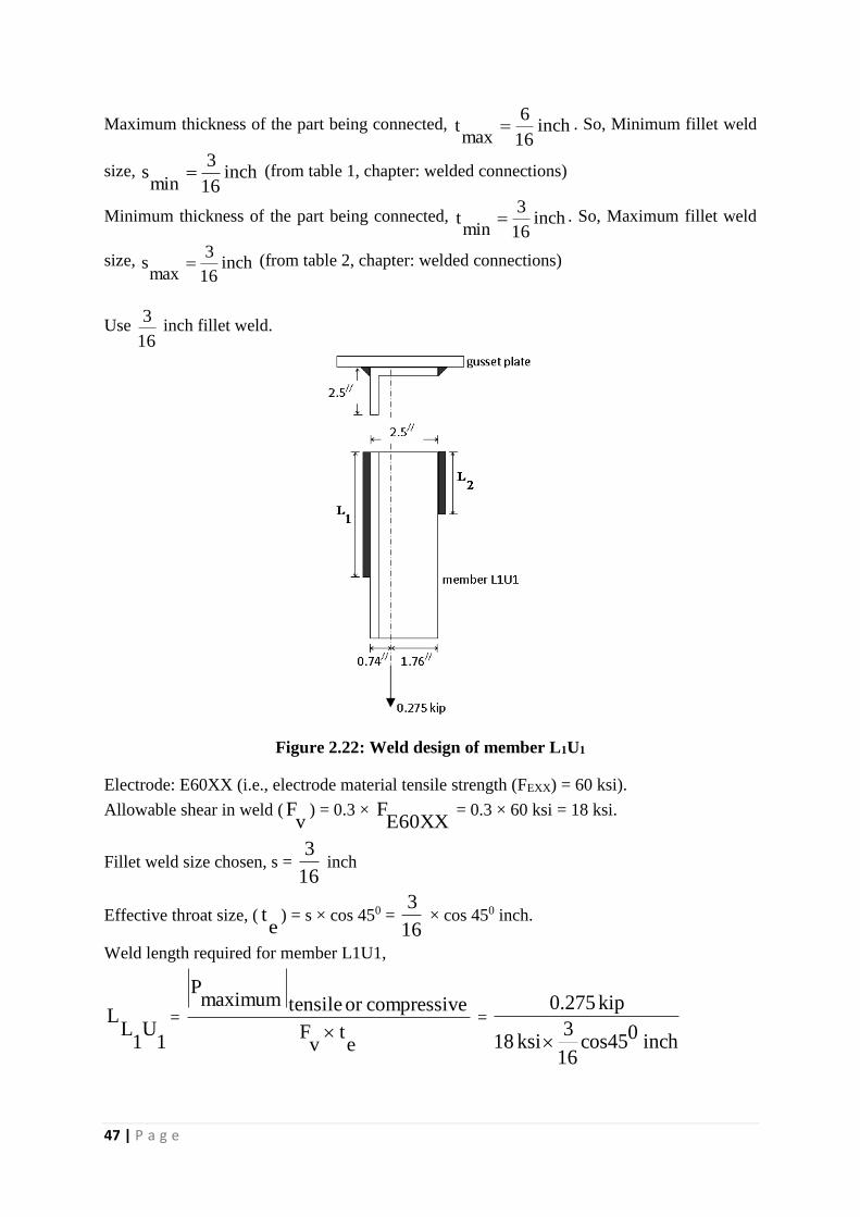
Electrode: E60XX (i.e., electrode material tensile strength (FEXX) = 60 ksi).
Allowable shear in weld (v
F ) = 0.3 × E60XX
F = 0.3 × 60 ksi = 18 ksi.
Fillet weld size chosen, s = 16
3 inch
Effective throat size, (e
t ) = s × cos 450 = 16
3 × cos 450 inch.
Weld length required for member L1U1,
1U
1L
L =
et
vF
ecompressivor tensilemaximumP
=
inch 0cos4516
3ksi 18
kip 0.275

48 | P a g e
1U
1L
L = 0.1152322 inch
1
L + 2
L =
1U
1L
L = 0.1152322 inch
Taking moment about 2
L ,
(1
L × e
t × v
F ) × (2.5//) = (0.275 kip) × (1.76//)
(1
L × 16
3 cos 450 inch ×18 ksi) × (2.5//) = (0.275 kip) × (1.76//)
1
L = 0.081123 inch ≈ 0.50 inch
Taking moment about 1
L ,
(2
L × e
t × v
F ) × (2.5//) = (0.275 kip) × (0.74//)
(2
L × 16
3 cos 450 inch ×18 ksi) × (2.5//) = (0.275 kip) × (0.74//)
2
L = 0.034108 inch ≈ 0.50 inch
Minimum weld length, minimum
L = 4 s = 4 × 16
3 = 0.75 inch
Both 1
L & 2
L > minimum
L ; OK
Alternatively, 1
L + 2
L = 0.1152322 inch &
2L
1L
= inch 1.04
inch 2.46; from which,
1L = 0.081123
inch & 2
L = 0.034108 inch.
Weld for U1L2:
Consider, U1L2 (16
3
2
123 L ) & gusset plate (
16
6 inch)
inch 16
6
maxt and inch
16
3
mint
Maximum thickness of the part being connected, inch 16
6
maxt . So, Minimum fillet weld
size, inch 16
3
mins

49 | P a g e
Minimum thickness of the part being connected, inch 16
3
mint . So, Maximum fillet weld
size, inch 16
3
maxs
Use 16
3 inch fillet weld.
Figure 2.23: Weld design of member U1L2
Electrode: E60XX (i.e., electrode material tensile strength (FEXX) = 60 ksi).
Allowable shear in weld (v
F ) = 0.3 × E60XX
F = 0.3 × 60 ksi = 18 ksi.
Fillet weld size chosen, s = 16
3 inch
Effective throat size, (e
t ) = s × cos 450 = 16
3 × cos 450 inch.
Weld length required for member L1U2,
1U
1L
L =
et
vF
ecompressivor tensilemaximumP
=
inch 0cos4516
3ksi 18
kip 12.003
1U
1L
L = 5.029571 inch
1
L + 2
L =
1U
1L
L = 5.029571 inch
Taking moment about 2
L ,

50 | P a g e
(1
L × e
t × v
F ) × (3//) = (12.003 kip) × (2.112//)
(1
L × 16
3 cos 450 inch ×18 ksi) × (3//) = (12.003 kip) × (2.112//)
1
L = 3.540818 inch ≈ 4 inch
Taking moment about 1
L ,
(2
L × e
t × v
F ) × (3//) = (12.003 kip) × (0.888//)
(2
L × 16
3 cos 450 inch ×18 ksi) × (3//) = (12.003 kip) × (0.888//)
2
L = 1.488753 inch ≈ 1.5 inch
Minimum weld length, minimum
L = 4 s = 4 × 16
3 = 0.75 inch
Both 1
L & 2
L > minimum
L ; OK
Alternatively, 1
L + 2
L = 5.029571 inch&
2L
1L
= inch 0.888
inch 2.112; from which,
1L = 3.540818
inch & 2
L = 1.488753 inch.
Figure 2.24(a): Weld design of joint U1

51 | P a g e
Figure 2.24(b): Weld design of joint U1
2.12 Design of Anchorage and Support:
The truss is supported by reinforced concrete columns and footings, their reactions having been
calculated earlier for point dead load and wind loads. The connections between the truss and
support are designed in this section for the combined design loads.
Combination of Support Reactions from Dead Load and Wind Load:
The calculation for the design support reactions is carried out in the following tabular form.
Since the truss is supported on base plates on concrete pedestals supported by masonry
columns, the design in this study deals mainly with the connections between the truss and the
columns. The column forces are nominal, therefore a 10”X20” masonry column is chosen. The
maximum tensile stress on the column = 29.29/(10*20) = 0.146 ksi, which is within the
allowable limit (Tensile strength 300 psi).
Assuming the base plate area = Ap and bearing pressure = 0.35 fc’ = 1.05 ksi
1.05Ap = 14.73
Ap = 14.73/1.05
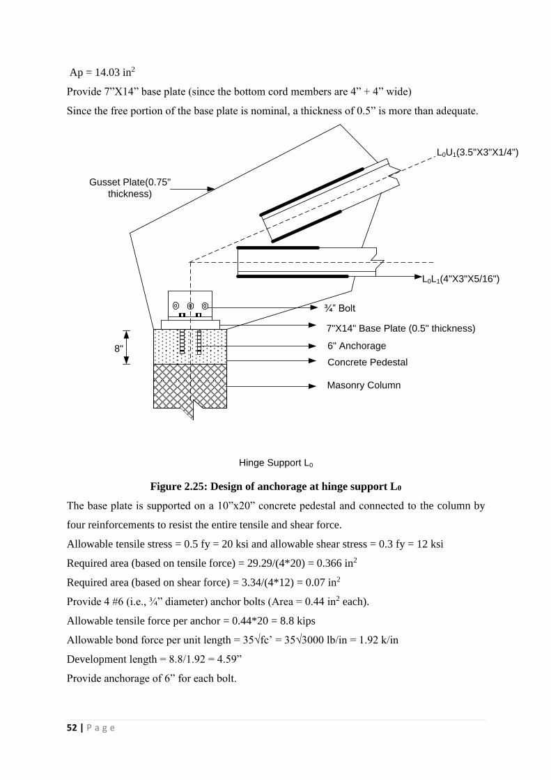
52 | P a g e
Ap = 14.03 in2
Provide 7”X14” base plate (since the bottom cord members are 4” + 4” wide)
Since the free portion of the base plate is nominal, a thickness of 0.5” is more than adequate.
¾” Bolt
7"X14" Base Plate (0.5" thickness)
6" Anchorage
Concrete Pedestal
8"
Masonry Column
L0L1(4"X3"X5/16")
L0U1(3.5"X3"X1/4")
Gusset Plate(0.75"
thickness)
Hinge Support L0
Figure 2.25: Design of anchorage at hinge support L0
The base plate is supported on a 10”x20” concrete pedestal and connected to the column by
four reinforcements to resist the entire tensile and shear force.
Allowable tensile stress = 0.5 fy = 20 ksi and allowable shear stress = 0.3 fy = 12 ksi
Required area (based on tensile force) = 29.29/(4*20) = 0.366 in2
Required area (based on shear force) = 3.34/(4*12) = 0.07 in2
Provide 4 #6 (i.e., ¾” diameter) anchor bolts (Area = 0.44 in2 each).
Allowable tensile force per anchor = 0.44*20 = 8.8 kips
Allowable bond force per unit length = 35√fc’ = 35√3000 lb/in = 1.92 k/in
Development length = 8.8/1.92 = 4.59”
Provide anchorage of 6” for each bolt.

53 | P a g e
The base plate will be connected to the gusset plate by the section similar to the bottom cord
(i.e., a 4X3X5/16 double angle section), also with ¾” diameter bolts to transfer the maximum
support reaction (= 29.29 kips) by shear.
Required area = 29.29/12 = 2.44 in2, i.e., provide 3-3/4” diameter bolts in double shear.
Roller Support L6
8"
L5L6(4"X3"X5/16")
L6U5(3.5"X3"X1/4")
Gusset Plate(0.75"
thickness)
6" Roller
Figure 2.26 Design of anchorage at roller support L6
54 | P a g e
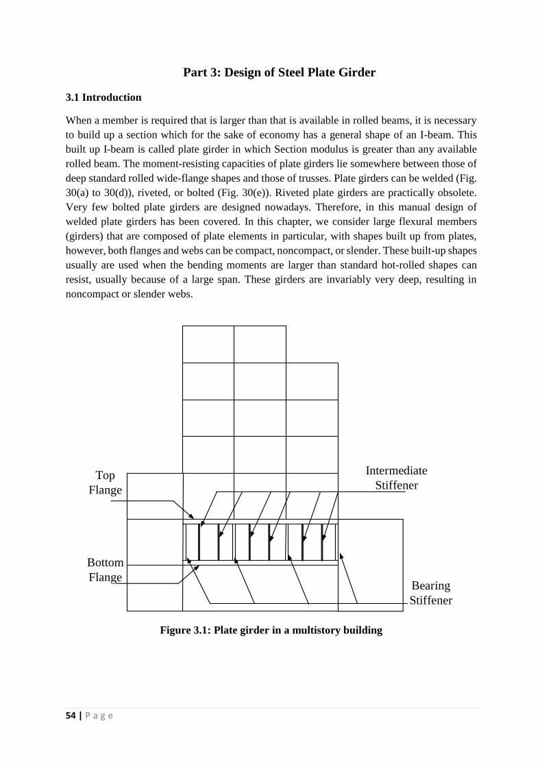
Part 3: Design of Steel Plate Girder
3.1 Introduction
When a member is required that is larger than that is available in rolled beams, it is necessary
to build up a section which for the sake of economy has a general shape of an I-beam. This
built up I-beam is called plate girder in which Section modulus is greater than any available
rolled beam. The moment-resisting capacities of plate girders lie somewhere between those of
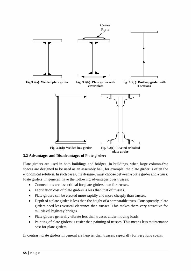
deep standard rolled wide-flange shapes and those of trusses. Plate girders can be welded (Fig.
30(a) to 30(d)), riveted, or bolted (Fig. 30(e)). Riveted plate girders are practically obsolete.
Very few bolted plate girders are designed nowadays. Therefore, in this manual design of
welded plate girders has been covered. In this chapter, we consider large flexural members
(girders) that are composed of plate elements in particular, with shapes built up from plates,
however, both flanges and webs can be compact, noncompact, or slender. These built-up shapes
usually are used when the bending moments are larger than standard hot-rolled shapes can
resist, usually because of a large span. These girders are invariably very deep, resulting in
noncompact or slender webs.
Intermediate
Stiffener
Bearing
Stiffener
Top
Flange
Bottom
Flange
Figure 3.1: Plate girder in a multistory building
55 | P a g e
Cover
Plate
Fig.3.2(a): Welded plate girder Fig. 3.2(b): Plate girder with
cover plate
Fig. 3.3(c): Built-up girder with
T sections
Fig. 3.2(d): Welded box girder Fig. 3.2(e): Riveted or bolted
plate girder
3.2 Advantages and Disadvantages of Plate girder:
Plate girders are used in both buildings and bridges. In buildings, when large column-free
spaces are designed to be used as an assembly hall, for example, the plate girder is often the
economical solution. In such cases, the designer must choose between a plate girder and a truss.
Plate girders, in general, have the following advantages over trusses:
• Connections are less critical for plate girders than for trusses.
• Fabrication cost of plate girders is less than that of trusses.
• Plate girders can be erected more rapidly and more cheaply than trusses.
• Depth of a plate girder is less than the height of a comparable truss. Consequently, plate
girders need less vertical clearance than trusses. This makes them very attractive for
multilevel highway bridges.
• Plate girders generally vibrate less than trusses under moving loads.
• Painting of plate girders is easier than painting of trusses. This means less maintenance
cost for plate girders.
In contrast, plate girders in general are heavier than trusses, especially for very long spans.

56 | P a g e
3.3 Types of Plate Girder:
There are different types of plate girder that are used in buildings and bridges.
• Box Girder: Providing improved torsional stiffness for long span bridges.
• Hybrid Girder: Providing variable material strength in accordance with stresses. In
order to reduce the girder weight and possibly achieve maximum economy, hybrid plate
girders are sometimes used. In a hybrid girder, flange plates are made of higher strength
steel than that of the web
• Delta girder: Delta girder, may be used for more stability of the compression flange.
Box girder
Delta girder
Fig. 1 Types of plate girder
Hybrid girder
Low strength web
High strength flange
3.4 Essential Elements of I-section Plate Girder:
In a built-up I section, there are some elements that need to be designed.
• Top flange
• Bottom flange
• Web
• Intermediate stiffener
• Bearing stiffener
• Welding
(a)
A
A
Figure 3.4(a): Plate girder without stiffeners
Figure 3.3: Types of plate girder

57 | P a g e
Top and bottom flange plate: Plate girders basically carry the loads by bending. The bending
moment is mostly carried by flange plates.
Web: A web plate is needed to unify the two flange plates and to carry the shear.
Intermediate Stiffener: In addition to flange plates and a web plate, a plate girder often
consists of stiffeners. Thin web plates are susceptible to unstable behavior. Thick web plates
make the girder unnecessarily heavy. A relatively thin web plate strengthened by stiffeners
often yields the lightest plate girder. Therefore, intermediate stiffeners are provided to stiffen
the web plate against buckling and to resist compressive forces transmitted from the web during
tension-field action.
Bearing Stiffener: Bearing stiffeners should always be provided in pairs at the ends of plate
girders and if required at points of application of concentrated loads. These bearing stiffeners
should extend roughly to the edges of the flange plates.
EP ITS ITS ITS ITS ITS EP
B
B
C
C
(b)
Figure 3.4(b): Plate girder with intermediate and bearing stiffeners
EP ITS ITS ITS ITS ITS EP
D
D
LS LSLSLS LSLS
(c)
Figure 3.4(c): Plate girder with intermediate, bearing and lateral stiffeners

58 | P a g e
Flange plate
Web plate
Section A-A Section B-B
EP
Section C-C
4tw
ITS
Section D-
D
4tw
ITS
LS
Fig. 1Forms of plate girder
3.5 Post-Buckling Behavior of the Web Plate:
A relatively thin web plate strengthened by stiffeners often yields the lightest plate girder.
Stiffened plate girders are designed on the basis of the ultimate strength concept. As the
magnitude of the load on the girder is increased, the web panels between adjacent vertical
stiffeners buckle due to diagonal compression resulting from shear. If the plate girder has
properly designed stiffeners, the instability of the web plate panels, bounded on all sides by the
transverse stiffeners of flanges, will not result in its failure. In fact, after the web panels buckle
in shear, the plate girder behaves like the Pratt truss shown in Fig. 3.5(a). It will then be able
to carry additional loads. A stiffened plate girder has considerable post-buckling strength.
The Pratt truss of Fig. 3.5(a) is subjected to a concentrated load applied at its midspan. In this
truss, the vertical members are in compression and the diagonals are in tension. The post-
buckling behavior of the plate girder is analogous to the behavior of this truss. As shown in
Fig. 33(b), after the shear instability of the web takes place, a redistribution of stresses occurs;
the stiffeners behave like axially compressed members, and shaded portions of the web behave
like tension diagonals in the truss of Fig. 33(a). This truss-like behavior is called tension-field
action in the literature. The post-buckling strength of the web plate may be three or four times
its initial buckling strength. Consequently, designs on the basis of tension-field action can yield
better economy.
A tension field ordinarily cannot be fully developed in an end panel. This can be understood
by considering the horizontal components of the tension fields shown in Figure 3.5(b). (The
vertical components are resisted by the stiffeners.) The tension field in panel CD is balanced
on the left side in part by the tension field in panel BC. Thus, interior panels are anchored by
adjacent panels. Panel AB, however, has no such anchorage on the left side. Hence the
anchorage for panel BC must be provided on the left side by a beam-shear panel rather than
the tension-field panel shown.
Figure 3.4(d): Forms of plate girder

59 | P a g e
P
Diagonal
MemberTop Chord
Vertical Member
Bottom Chord
(a)
PPortion of web
under tensionTop flange
Intermediate stiffener
(b)
A B C D
Web
Bottom flange
Figure 3.5: Analogy between a truss and a stiffened plate girder
AISC G3.1 lists all of the conditions under which a tension field cannot be used:
𝑎. In end panels
𝑏. When. 𝑎
ℎ< 3 or.
𝑎
ℎ< (
260
ℎ/𝑡𝑤)2 (Each of these cases corresponds to 𝑘𝑣 = 5)
𝑐. When 2𝐴𝑤
(𝐴𝑓𝑐+𝐴𝑓𝑡)> 2.5
𝑑. When ℎ
𝑏𝑓𝑐 or
ℎ
𝑏𝑓𝑡> 6
Where,
𝐴𝑤 =area of the web
𝐴𝑓𝑐 =area ofthe compression flange
𝐴𝑓𝑡 =area of the tension flange
𝑏𝑓𝑐 =width ofthe compression flange
𝑏𝑓𝑡 =width of the tension flange

60 | P a g e
3.6 Requirements for different components of the plate girder
3.6.1 Proportions of Plate Girders:
Whether a girder web is noncompact or slender depends on ℎ/𝑡𝑤, the width‐to‐thickness ratio
of the web, where ℎ is the depth ofthe web from inside face of flange to inside face of flange
and 𝑡𝑤 is the web thickness. From AISC B4 the web of a doubly symmetric I‐shaped section
is noncompact if
3.76√𝐸
𝐹𝑦<
ℎ
𝑡𝑤≤ 5.70√
𝐸
𝐹𝑦
and the web is slender if
ℎ
𝑡𝑤> 5.70√
𝐸
𝐹𝑦
To prevent vertical buckling of the compression flange into the web, AISC F13.2 imposes an
upper limit on the web slenderness. The limiting value of ℎ/𝑡𝑤 is a function of the aspect ratio,
𝑎/ℎ, ofthe girder panels, which is the ratio of intermediate stiffener spacing to web depth
For 𝑎
ℎ ≤ 1.5, (
ℎ
𝑡𝑤) max = 12.0√
𝐸
𝐹𝑦
For 𝑎
ℎ > 1.5, (
ℎ
𝑡𝑤) max =
0.40𝐸
𝐹𝑦
Where, 𝑎 is the clear distance between stiffeners.
3.6.2 Requirement for Flexural Strength
The nominal flexural strength 𝑀𝑛 of a plate girder is based on one of the limit states of tension
flange yielding, compression flange yielding or local buckling (FLB), or lateral torsional
buckling (LTB). The aspects related to flexural strength are discussed in AISC chapter F.
Tension Flange Yielding
AISC F5 gives the nominal flexural strength based on tension flange yielding as
𝑀𝑛 = 𝐹𝑦𝑆𝑥𝑡
where 𝑆𝑥𝑡 =elastic section modulus referred to the tension side.
(3.1)
(3.2)
(3.3)
(3.4)
𝑡𝑤
Section- Front View Section- Side View
a h
Figure 3.6: Front and side view of the plate girder
(3.5)
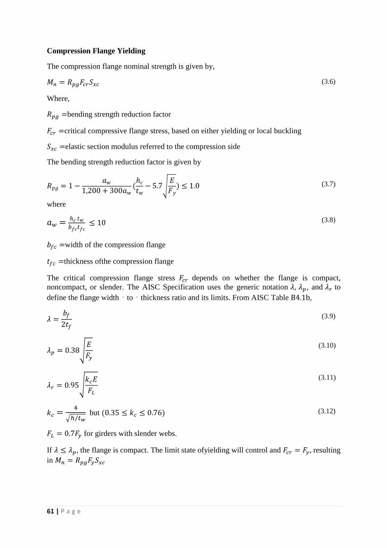
61 | P a g e
Compression Flange Yielding
The compression flange nominal strength is given by,
𝑀𝑛 = 𝑅𝑝𝑔𝐹𝑐𝑟𝑆𝑥𝑐
Where,
𝑅𝑝𝑔 =bending strength reduction factor
𝐹𝑐𝑟 =critical compressive flange stress, based on either yielding or local buckling
𝑆𝑥𝑐 =elastic section modulus referred to the compression side
The bending strength reduction factor is given by
𝑅𝑝𝑔 = 1 −𝑎𝑤
1,200 + 300𝑎𝑤(ℎ𝑐
𝑡𝑤− 5.7√
𝐸
𝐹𝑦) ≤ 1.0
where
𝑎𝑤 =ℎ𝑐 𝑡𝑤
𝑏𝑓𝑐𝑡𝑓𝑐 ≤ 10
𝑏𝑓𝑐 =width of the compression flange
𝑡𝑓𝑐 =thickness ofthe compression flange
The critical compression flange stress 𝐹𝑐𝑟 depends on whether the flange is compact,
noncompact, or slender. The AISC Specification uses the generic notation 𝜆, 𝜆𝑝, and 𝜆𝑟 to
define the flange width‐to‐thickness ratio and its limits. From AISC Table B4.1b,
𝜆 =𝑏𝑓
2𝑡𝑓
𝜆𝑝 = 0.38√𝐸
𝐹𝑦
𝜆𝑟 = 0.95√𝑘𝑐𝐸
𝐹𝐿
𝑘𝑐 =4
√ℎ/𝑡𝑤 but (0.35 ≤ 𝑘𝑐 ≤ 0.76)
𝐹𝐿 = 0.7𝐹𝑦 for girders with slender webs.
If 𝜆 ≤ 𝜆𝑝, the flange is compact. The limit state ofyielding will control and 𝐹𝑐𝑟 = 𝐹𝑦, resulting
in 𝑀𝑛 = 𝑅𝑝𝑔𝐹𝑦𝑆𝑥𝑐
(3.6)
(3.7)
(3.8)
(3.10)
(3.11)
(3.9)
(3.12)
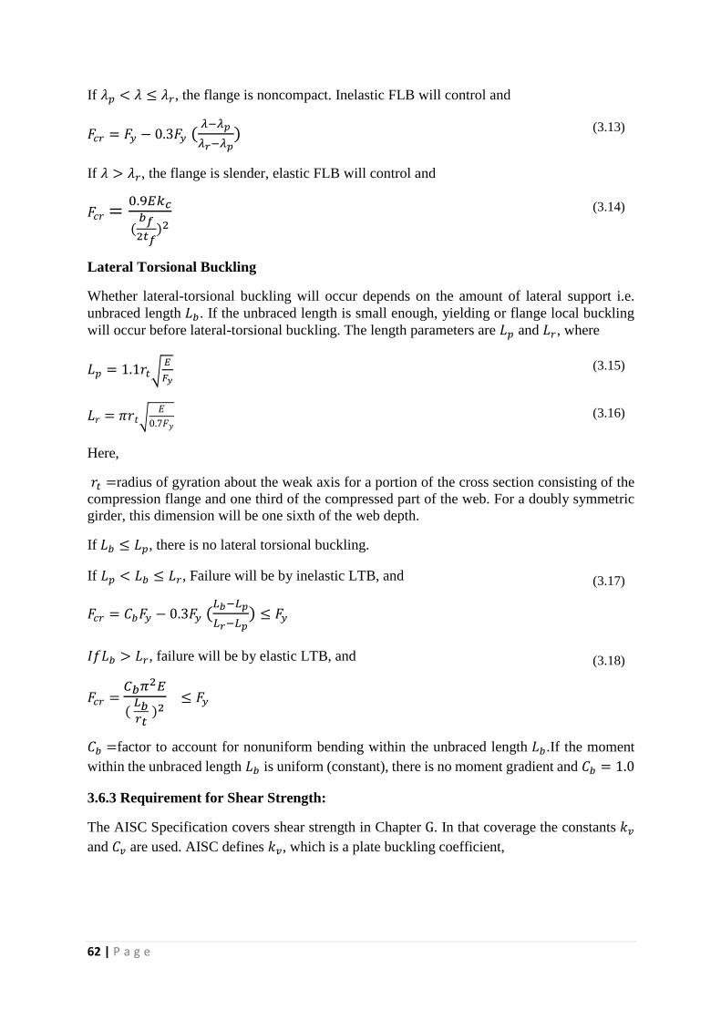
62 | P a g e
If 𝜆𝑝 < 𝜆 ≤ 𝜆𝑟, the flange is noncompact. Inelastic FLB will control and
𝐹𝑐𝑟 = 𝐹𝑦 − 0.3𝐹𝑦 (𝜆−𝜆𝑝
𝜆𝑟−𝜆𝑝)
If 𝜆 > 𝜆𝑟, the flange is slender, elastic FLB will control and
𝐹𝑐𝑟 =0.9𝐸𝑘𝑐
(𝑏𝑓
2𝑡𝑓)2
Lateral Torsional Buckling
Whether lateral-torsional buckling will occur depends on the amount of lateral support i.e.
unbraced length 𝐿𝑏. If the unbraced length is small enough, yielding or flange local buckling
will occur before lateral-torsional buckling. The length parameters are 𝐿𝑝 and 𝐿𝑟, where
𝐿𝑝 = 1.1𝑟𝑡√𝐸
𝐹𝑦
𝐿𝑟 = 𝜋𝑟𝑡√𝐸
0.7𝐹𝑦
Here,
𝑟𝑡 =radius of gyration about the weak axis for a portion of the cross section consisting of the
compression flange and one third of the compressed part of the web. For a doubly symmetric
girder, this dimension will be one sixth of the web depth.
If 𝐿𝑏 ≤ 𝐿𝑝, there is no lateral torsional buckling.
If 𝐿𝑝 < 𝐿𝑏 ≤ 𝐿𝑟, Failure will be by inelastic LTB, and
𝐹𝑐𝑟 = 𝐶𝑏𝐹𝑦 − 0.3𝐹𝑦 (𝐿𝑏−𝐿𝑝
𝐿𝑟−𝐿𝑝) ≤ 𝐹𝑦
𝐼𝑓𝐿𝑏 > 𝐿𝑟, failure will be by elastic LTB, and
𝐹𝑐𝑟 = 𝐶𝑏𝜋2𝐸
( 𝐿𝑏𝑟𝑡
)2 ≤ 𝐹𝑦
𝐶𝑏 =factor to account for nonuniform bending within the unbraced length 𝐿𝑏.If the moment
within the unbraced length 𝐿𝑏 is uniform (constant), there is no moment gradient and 𝐶𝑏 = 1.0
3.6.3 Requirement for Shear Strength:
The AISC Specification covers shear strength in Chapter G. In that coverage the constants 𝑘𝑣
and 𝐶𝑣 are used. AISC defines 𝑘𝑣, which is a plate buckling coefficient,
(3.13)
(3.14)
(3.15)
(3.16)
(3.17)
(3.18)

63 | P a g e
𝑘𝑣 = 5 +5
(𝑎/ℎ)2
= 5 if 𝑎
ℎ > 3
= 5 if 𝑎
ℎ > (
260
ℎ/𝑡𝑤)2
= 5 in unstiffened webs with ℎ
𝑡𝑤 < 260
For 𝐶𝑣, which can be defined as the ratio of the critical web shear stress to the web shear yield
stress,
If ℎ
𝑡𝑤 ≤ 1.10 √
𝑘𝑣𝐸
𝐹𝑦, 𝐶𝑣 = 1.0
If 1.10 √𝑘𝑣𝐸
𝐹𝑦 <
ℎ
𝑡𝑤 ≤ 1.37 √
𝑘𝑣𝐸
𝐹𝑦, 𝐶𝑣 =
1.10√𝑘𝑣𝐸/𝐹𝑦
ℎ/𝑡𝑤
If ℎ
𝑡𝑤> 1.37 √
𝑘𝑣𝐸
𝐹𝑦
, 𝐶𝑣 =1.51𝑘𝑣𝐸
(ℎ/𝑡𝑤)2𝐹𝑦
Whether the shear strength is based on web shear yielding or web shear buckling depends on
the web width to thickness ratio ℎ/𝑡𝑤. If
ℎ
𝑡𝑤≤ 1.10√
𝑘𝑣𝐸
𝐹𝑦
the strength is based on shear yielding, and 𝑉𝑛 = 0.6𝐹𝑦𝐴𝑤
where 𝐴𝑤 =cross-sectional area of the web. If
ℎ
𝑡𝑤> 1.10√
𝑘𝑣𝐸
𝐹𝑦,
the strength will be based on shear buckling or shear buckling plus tension field action. If
tension field behavior exists,
AISC Equation G3‐2 can also be written as
𝑉𝑛 = 0.6𝐹𝑦𝐴𝑤𝐶𝑣 + 0.6𝐹𝑦𝐴𝑤
1 − 𝐶𝑣
1.15√1 + (𝑎/ℎ)2
(3.19)
(3.20)
(3.21)
(3.23)
(3.24)
(3.22)

64 | P a g e
The first term in the equation gives the web shear buckling strength and the second term gives
the post buckling strength. If there is no tension field action, the second term is omitted,
resulting in
𝑉𝑛 = 0.6𝐹𝑦𝐴𝑤𝐶𝑣
Solution of AISC Equations G2-1 (without tension field) and G3-2 (with tension field) is
facilitated by curves given in Part 3 of the Manual. Tables 3-16a and 3-16b present curves that
relate the variables of these two equations for steel with a yield stress of 36 ksi and Tables 3-
17a and 3-17b do the same for steels with a yield stress of 50 ksi.
3.6.4 Requirements for Intermediate Stiffener
Without a Tension Field:
The requirements for stiffeners when a tension field is not present are given in AISC G2.2. The
required moment of inertia of a pair of stiffeners about an axis through the web is
𝐼𝑠𝑡 ≥ 𝑏𝑡𝑤3 𝑗
Where,
𝑗 =2.5
(𝑎/ℎ)2 −2 ≥ 0.5
𝑏 =smaller of 𝑎 and ℎ.
With a Tension Field
The requirements for stiffeners where tension field action is used are given in AISC G3.3. The
first requirement is for the proportions of the stiffener.
( 𝑏
t )𝑠𝑡 ≤ 0.56√
𝐸
𝐹𝑦𝑠𝑡
Where,
( 𝑏
t )𝑠𝑡 =width to thickness ratio of the stiffener cross section
𝐹𝑦𝑠𝑡 =yield stress ofthe stiffener
The second requirement is for the moment of inertia of the stiffener or pair of stiffeners.
𝐼𝑠𝑡 ≥ 𝐼𝑠𝑡1 + (𝐼𝑠𝑡2 − 𝐼𝑠𝑡1)𝑉𝑟 − 𝑉𝑐1
𝑉𝑐2 − 𝑉𝑐1
Where,
𝐼𝑠𝑡1 =required moment of inertia as calculated for the no tension field case
(3.25)
(3.27)
(3.28)
(3.29)
(3.26)

65 | P a g e
𝐼𝑠𝑡2 = moment of inertia required to develop the buckling plus post buckling shear strength
=ℎ4𝑝𝑠𝑡
1.3
40(
𝐹𝑦𝑤
𝐸 )1.5
𝑝𝑠𝑡 = max ( 𝐹𝑦𝑤
𝐹𝑦𝑠𝑡, 1 )
𝐹𝑦𝑤 =yield stress ofthe girder web
𝑉𝑟 = the larger of the required shear strengths (𝑉𝑢 𝑓𝑜𝑟 LRFD, 𝑉𝑎 for ASD) on each side of the
stiffener; that is, in the adjacent web panels
𝑉𝑐1 = the smaller of the available shear strengths ( (𝜑𝑣𝑉𝑛 for LRFD, 𝑉𝑛/𝛺𝑣 for ASD) in the
adjacent panels, calculated with no tension field action
𝑉𝑐2 = 𝑡ℎ𝑒 smaller of the available shear strengths ( (𝜑𝑣𝑉𝑛 for LRFD, V/𝛺𝑣 for ASD) in the
adjacent panels, calculated with tension field action
3.6.5 Requirements for Bearing Stiffener
Although the web can be proportioned to directly resist any applied concentrated loads, bearing
stiffeners are usually provided. If stiffeners are used to resist the full concentrated load, the
limit states of web yielding, web crippling, and side-sway web buckling do not need to be
checked. The nominal bearing strength of a stiffener is given in AISC J7 as,
𝑅𝑛 = 1.8𝐹𝑦𝐴𝑝𝑏
For LRFD, the resistance factor is 𝜑 = 0.75. For ASD, the safety factor is 𝛺 = 2.00.
Full depth stiffeners should be used in pairs and analyzed as axially loaded columns subject to
the following guidelines:
• The cross section of the axially loaded member consists of the stiffener plates and a
length of the web This length can be no greater than 12 times the web thickness for an
end stiffener or 25 times the web thickness for an interior stiffener.
• The effective length should be taken as 0.75 times the actual length that is, 𝐾𝐿 = 0.75ℎ.
• The nominal axial strength is based on the provisions of AISC J4.4, “Strength of
Elements in Compression which are as follows:
For 𝐾𝐿
𝑟≤ 25
𝑃𝑛 = 𝐹𝑦𝐴𝑔
This is the squash load for the stiffener that causes compression yielding with no
buckling. For LRFD, the resistance factor for this limit state is 𝜑 = 0.90, for ASD, the
safety factor is 𝛺 = 1.67. For 𝐾𝐿
𝑟 > 25 , the usual requirements for compression
members apply
(3.30)
(3.31)
(3.32)

66 | P a g e
• The weld connecting the stiffener to the web should have the capacity to transfer the
unbalanced force. Conservatively, the weld can be designed to carry the entire
concentrated load. If the stiffener bears on the compression flange, it need not be welded
to the flange.
Although no width to thickness ratio limit is given in the Specification for bearing stiffeners,
the requirement of AISC Equation G3-3 for intermediate stiffeners can be used as a guide in
proportioning bearing stiffeners:
( 𝑏
𝑡 )𝑠𝑡 ≤ 0.56√
𝐸
𝐹𝑦𝑠𝑡
3.7 Design Procedure
The primary task in plate girder design is to determine the size of the web and the flanges. If a
variable moment of inertia is desired, decisions must be made regarding the method of varying
the flange size—that is, whether to use cover plates or different thicknesses of flange plate at
different points along the length of the girder. A decision about whether to use intermediate
stiffeners must be made early in the process because it will affect the web thickness. If bearing
stiffeners are needed, they must be designed. Finally, the various components must be
connected by properly designed welds. The following step-by-step procedure is recommended.
1. Select the overall depth. The optimum depth of a girder depends on the situation. Some
authors recommend an overall depth of 1
10 to
1
12 of the span length. Others suggest a range of
1
6 to
1
20 give procedures for determining the depth that incorporate the required moment
strength and a specified h
𝑡𝑤 ratio. As with any beam design, constraints on the maximum depth
could establish the depth by default.
2. Select a trial web size. The web depth can be estimated by subtracting twice the flange
thickness from the overall depth selected. Of course, at this stage of the design, the flange
thickness must also be estimated. The web thickness 𝑡𝑤 can then be found by using the
following limitations as a guide. Once ℎ and 𝑡𝑤 have been selected, determine whether the web
width to thickness ratio qualifies this member as a slender-web flexural member. If so, the
provisions of AISC F5 can be used. (If the web is noncompact, AISC F5 can still be used, but
it will be conservative)
3. Estimate the flange size: The required flange area can be estimated from a simple formula
derived as follows.
𝐴𝑓 =𝑀𝑛𝑟𝑒𝑞
ℎ𝑅𝑝𝑔𝐹𝑐𝑟−
𝑡𝑤ℎ
6
If we assume that 𝑅𝑝𝑔 = 1.0 and 𝐹𝑐𝑟 = 𝐹𝑦, the required area of one flange is
𝐴𝑓 =𝑀𝑛𝑟𝑒𝑞
ℎ𝐹𝑦−
𝐴𝑤
6 …………………(3.33)

67 | P a g e
Where,
𝑀𝑛𝑟𝑒𝑞 =Required nominal flexural strength
= 𝑀𝒰/𝜑𝑏 for LRFD
= 𝛺𝑏𝑀𝑎 for ASD
𝐴𝑤 = web area
Once the required flange area has been determined, select the width and thickness. If the
thickness originally used in the estimate of the web depth is retained, no adjustment in the web
depth will be needed. Otherwise changes have to be made regarding previously selected
components. At this point, an estimated girder weight can be computed, then 𝑀𝑛𝑟𝑒𝑞 should be
recomputed.
4. Check the bending strength of the trial section.
5. Determine intermediate stiffener spacings and check the shear strength of the trial section.
The design curves in Part 3 of the AISC Manual can be used for this purpose or AISC Equation
G3-1 and G3-2
6. Design intermediate stiffeners. If there is not a tension field, the intermediate stiffeners must
be proportioned to satisfy the moment of inertia requirement of AISC Equation G2-7. If there
is a tension field, the width to thickness ratio limit of AISC Equation G3-3 and the moment of
inertia requirement of AISC Equation G3-4 must be satisfied.
7. Design bearing stiffeners. To determine whether bearing stiffeners are needed, check the
web resistance to concentrated loads (web yielding, web crippling, and web sidesway
buckling). Alternatively, bearing stiffeners can be provided to fully resist the concentrated
loads, and the web need not be checked. If bearing stiffeners are used, the following design
procedure can be used.
𝑎. Try a width that brings the edge ofthe stiffener near the edge of the flange and a thickness
that satisfies AISC Equation G3-3:
( 𝑏
𝑡 )𝑠𝑡 ≤ 0.56√
𝐸
𝐹𝑦𝑠𝑡
𝑏. Compute the cross‐sectional area needed for bearing strength. Compare this area with the
trial area and revise if necessary.
𝑐. Check the stiffener-web assembly as a compression member.
8. Design the flange-to-web welds, stiffener-to-web welds, and any other connections (flange
segments, web splices, etc.)

68 | P a g e
3.8 Design Example
Problem Description
Fig 3.7: Beam Layout
Design the internal plate girder where,
Thickness of the slab = 5 in
maximum permissible depth of beam = 65 in
Concentrated load, 𝑃𝐷 = 78 kip & 𝑃𝐿 = 58 kip are applied at the midpoint
Steel used = A36 (Fy = 36 ksi)
Electrode: E70XX (for welding)
Assume that the girder has lateral support at the ends and at the point of application of
concentrated load. The girder is restrained against rotation at these points.
Solution:
The tributary are for the internal beam, A = 0.5 (60+40)(10)2 = 1000 ft2
Assume floor finish = 40 psf and Live load on slab= 75 psf
∴ Service dead load, 𝑤𝐷 = (150×5/12+40) (1000
60) (
1
1000) = 1.70 k/ft
∴ Service live load, 𝑤𝐿= 75 (1000
60) (
1
1000) = 1.25 k/ft
Figure 3.8: Plate girder to be designed under service loads
60 ft
20 ft
20 ft
30' 30'
𝑃𝐷 = 78 kip
𝑃𝐿 = 58 kip
𝑤𝐷 = 1.70 kip/ft
𝑤𝐿 = 1.25 kip/ft

69 | P a g e
Factored loads = 1.2 × Dead Load + 1.6 × Live Load
∴ Total concentrated load = 1.2 × 78 + 1.6 × 58 = 186.4 kip
∴ Total uniform load = 1.2 × 1.70 + 1.6 × 1.25 = 4.04 kip/ft
Figure 3.9: Factored Loads (excluding girder self-weight)
Selection of Web Plate:
Determine the overall depth.
Span Length
10=
60(12)
10= 72 in.
Span Length
10=
60(12)
12= 60 in.
Use the maximum permissible depth of 65 inches.
Try a flange thickness of 𝑡𝑓 = 15 inches and a web depth of
ℎ = 65 − 2(1.5) = 62 in.
To determine the web thickness, first the limiting values of ℎ/𝑡𝑤 have to be examined
From Equations 3.3 and 3.4:
For 𝑎
ℎ≤ 1.5,
(h
tw) max = 12.0√
𝐸
𝐹𝑦= 12.0√
29,000
36= 340.6
min tw = 62
340.6 = 0.182 in.
For 𝑎
ℎ> 1.5,
(ℎ
𝑡𝑤) max =
0.40𝐸
𝐹𝑦=
0.40(29,000)
36= 322.2
30' 30'
186.4 kip
4.04 kip/ft
65 in
1.5 in
h
Figure 3.10: Cross-section of the plate
girder
70 | P a g e
min 𝑡𝑤 = 62
322.2 = 0.192 in.
Try a 𝟓 𝟏𝟔⁄ × 𝟔𝟐 web plate.
Determine whether the web is slender
ℎ
𝑡𝑤=
62
5/16= 198.4
5.70 √𝐸
𝐹𝑦 = 5.70 √
29,000
36 = 161.8 < 198.4
∴The web is slender. So, the AISC provisions for plate girder can be used.
Selection of Flange Size
Determine the required flange size. From Fig.3.9, the maximum factored load bending moment
is
𝑀𝑢 = 186.4(60)
4+
4.040(60)2
8 = 4614 ft-kips
∴ The required flange area is, 𝐴𝑓 =𝑀𝑛𝑟𝑒𝑞
ℎ𝐹𝑦−
𝐴𝑤
6
=𝑀𝑢/𝜑𝑏
ℎ𝐹𝑦−
𝐴𝑤
6
= (4614×12)/0.90
62(36)−
62(5/16)
6 = 24.33 in2
If the original estimate of the flange thickness is retained, the required width is
𝑏𝑓 = 𝐴𝑓
𝑡𝑓=
24.33
1.5 = 16.2 in.
Try a 𝟏 𝟏𝟐⁄ × 𝟏𝟖 flange plate.
The girder weight can now be computed.
Web area: 62(5/16) = 19.38 in.2
Flange area: 2(15 × 18) = 54.00 in.2
Total: 73.38 in2
Weight = 73.38
144 =(490) = 250 lb/ft (Self-weight of structural steel = 490 lb/ft3)
The adjusted bending moment is

71 | P a g e
𝑀𝑢 = 4614 + (1.2×0.250)(60)2
8 = 4749 ft-kips
Figure 3.11 shows the trial section, and Figure 3.12 shows the shear and bending moment
diagrams for the factored loads, which include the girder weight of 250 lb/ft.
Check the flexural strength of the trial section.
From Figure 3.11, the moment of inertia about the axis of bending is
𝑙x =(5/16)(62)3
12+ 2(1.5)(18)(31.75)2 = 60,640 in4
and the elastic section modulus is
𝑆𝑋 =𝐼𝑥
𝑐=
60,640
32.5= 1866 in3
Figure 3.11: Cross-section of the plate
girder
18 in
65 in
1.5 in
62 in 5/16 in
30' 30'
223.4 k
93.2 k
4749 k-ft
Figure 3.12: SFD and BMD for the recomputed factored
loads
186.4 kip
4.34 kip/ft

72 | P a g e
An examination of AISC Equations F5-7 and F5-10 shows that for a girder with a symmetrical
cross section, the flexural strength will never be controlled by tension flange yielding.
Check for compression flange buckling:
Determine whether the compression flange is compact, noncompact, or slender. (use Equations
3.9 to 3.12)
𝜆 =𝑏𝑓
2𝑡𝑓=
18
2(15)= 6.0
𝜆𝑝 = 0.38√𝐸
𝐹𝑦= 0.3𝑠√
29,000
36= 10.79
Since 𝜆 < 𝜆𝑝, there is no flange local buckling. The compression flange strength is therefore
based on yielding, and 𝐹𝑐𝑟 = 𝐹𝑦 = 36 ksi
To compute the plate girder strength reduction factor 𝑅𝑝𝑔, the value of 𝑎𝑤 will be needed:
𝑎𝑤 =ℎ𝑐𝑡𝑤
𝑏𝑓𝑐𝑡𝑓𝑐=
62(5/16)
18(1.5)= 0.7176 < 10
From Equation-7
𝑅𝑝𝑔 = 1 −𝑎𝑤
1,200 + 300𝑎𝑤(ℎ𝑐
𝑡𝑤− 5.7√
𝐸
𝐹𝑦) ≤ 1.0
= 1 −0.7176
1200 + 300(0.7176)(198.4 − 5.7√
29000
36) ≤ 1.0
= 0.9814
From AISC Equation F5-7, the nominal flexural strength for the compression flange is
𝑀𝑛 = 𝑅𝑝𝑔𝐹𝑐𝑟𝑆xc = 0.9814(36)(1866) = 65,930 in.‐kips = 5494ft −kips
and the design strength is
𝜑𝑏𝑀𝑛 = 0.90(5494) = 4945 ft-kips > 4749 ft‐kips (OK)
Although this capacity is somewhat more than needed, the excess will compensate for the
weight of stiffeners and other incidentals that have not yet been accounted for.
Check for lateral torsional buckling:
𝐼𝑦 =1
12(1.5)(18)3 +
1
12(62/6)(
5
16)3 = 729.03 i𝑛4
𝐴 = 18(1.5) + 10.333 (5
16) = 30.23 𝑖𝑛2
1.5 in
5/16 in
18"
62/6
Figure 3.13: Zone corresponding to lateral torsional
buckling
in
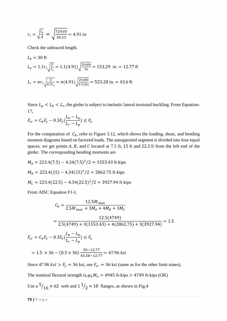
73 | P a g e
𝑟𝑡 = √𝐼𝑦
𝐴 = √
729.03
30.23 = 4.91 𝑖𝑛
Check the unbraced length.
𝐿𝑏 = 30 ft
𝐿𝑝 = 1.1𝑟𝑡√𝐸
𝐹𝑦= 1.1(4.91)√
29,000
36= 153.29 in. = 12.77 ft
𝐿𝑟 = 𝜋𝑟𝑡√𝐸
0.7𝐹𝑦= 𝜋(4.91)√
29,000
0.7(36)= 523.28 in. = 43.6 ft
Since 𝐿𝑝 < 𝐿𝑏 < 𝐿𝑟, the girder is subject to inelastic lateral torsional buckling. From Equation-
17,
𝐹𝑐𝑟 = 𝐶𝑏𝐹𝑦 − 0.3𝐹𝑦(𝐿𝑏 − 𝐿𝑝
𝐿𝑟 − 𝐿𝑝) ≤ 𝐹𝑦
For the computation of 𝐶𝑏, refer to Figure 3.12, which shows the loading, shear, and bending
moment diagrams based on factored loads. The unsupported segment is divided into four equal
spaces, we get points 𝐴, 𝐵, and 𝐶 located at 7.5 ft, 15 ft and 22.2 ft from the left end of the
girder. The corresponding bending moments are
𝑀𝐴 = 223.4(7.5) − 4.34(7.5)2/2 = 1553.43 ft-kips
𝑀𝐵 = 223.4(15) − 4.34(15)2/2 = 2862.75 ft-kips
𝑀𝐶 = 223.4(22.5) − 4.34(22.5)2/2 = 3927.94 ft-kips
From AISC Equation F1-l,
𝐶𝑏 =12.5𝑀 max
2.5𝑀 max + 3𝑀𝐴 + 4𝑀𝐵 + 3𝑀𝐶
=12.5(4749)
2.5(4749) + 3(1553.43) + 4(2862.75) + 3(3927.94)= 1.5
𝐹𝑐𝑟 = 𝐶𝑏𝐹𝑦 − 0.3𝐹𝑦(𝐿𝑏 − 𝐿𝑝
𝐿𝑟 − 𝐿𝑝) ≤ 𝐹𝑦
= 1.5 × 36 − (0.3 × 36) 30−12.77
43.58−12.77 = 47.96 ksi
Since 47.96 𝑘𝑠𝑖 > 𝐹𝑦 = 36 ksi, use 𝐹𝑐𝑟 = 36 ksi (same as for the other limit states).
The nominal flexural strength is,𝜑𝑏𝑀𝑛 = 4945 ft-kips > 4749 ft-kips (OK)
Use a 5 16⁄ × 62 web and 1 12⁄ × 18 flanges, as shown in Fig.4

74 | P a g e
Select intermediate stiffener spacing and check the corresponding shear strength
The shear is maximum at the support, but tension field action cannot be used in an end panel.
Table 3-16a in Part 3 of the AISC Manual can used to obtain the required size of the end panel.
The curves will be entered with values of ℎ/𝑡𝑤 and the required 𝜑𝑣𝑉𝑛/𝐴𝑤,
Where,
ℎ
𝑡𝑤= 198.4
𝐴𝑤 = 62(5
16) = 19.38 in.2
Required 𝜑𝑣𝑉𝑛
𝐴𝑤=
𝑉𝑢
𝐴𝑤=
223.4
19.38 = 11.5 ksi
Using ℎ/𝑡𝑤 = 198 and 𝜑𝑣𝑉𝑛/𝐴𝑤 = 12 ksi, we get a value of 𝑎/ℎ of approximately 0.60. The
corresponding intermediate stiffener spacing is
𝑎 = 0.60ℎ = 0.60(62) = 37.2 in.
Although the required stiffener spacing is a clear distance, the use of center to center distances
is somewhat simpler and will be slightly conservative. In addition, because of the
approximations involved in using the curves, we will be conservative in rounding the value of
𝑎. Use a distance of 36 inches from the center of the end bearing stiffener to the center of the
first intermediate stiffener.
Now, 𝑎 = 36 𝑖𝑛 ∴ 𝑎
ℎ =
36
62 = 0.58
From Equation-19,
𝑘𝑣 = 5 +5
(𝑎/ℎ)2 = 19.86
ℎ
𝑡𝑤 = 198.4
1.10 √𝑘𝑣𝐸
𝐹𝑦 = 1.10 √
19.86(29000)
36 = 139.13
1.37 √𝑘𝑣𝐸
𝐹𝑦 = 1.37 √
19.86(29000)
36 =173.28
∴ ℎ
𝑡𝑤> 1.37 √
𝑘𝑣𝐸
𝐹𝑦
So, from Equation-22, 𝐶𝑣 =1.51𝑘𝑣𝐸
(ℎ/𝑡𝑤)2𝐹𝑦 =0.61
As no tension field action occurs at the end panel, from equation-25
𝑉𝑛 = 0.6𝐹𝑦𝐴𝑤𝐶𝑣 = 0.6 (36) (19.375) (0.61) =255.285 kip

75 | P a g e
𝜑𝑉𝑛= 0.9 (255.285) = 229.76 kip >223.4 kip (OK)
Determine the intermediate stiffener spacings needed for shear strength outside the end panels.
At a distance of 36 inches from the left end, the shear is
𝑉𝑢 = 223.4 − 4.34 (36
12) = 210.4 kips
Required 𝜑𝑣𝑉𝑛
𝐴𝑤=
210.4
19.38 = 10.86 ksi
Tension field action can be used outside the end panels, so the curves of AISC Table 3-16b
will be used. For ℎ/𝑡𝑤 = 198 and 𝜑𝑣𝑉𝑛/𝐴𝑤 = 11 ksi,
𝑎
ℎ= 1.60
The required stiffener spacing is, 𝑎 = 1.60ℎ = 1.60(62) = 99.2 in.
This maximum spacing will apply for the remaining distance to the centerline of the girder.
This distance is
30(12) − 36 = 324 in.
The number of spaces required is, 324
99.2 = 3.27
Use four spaces. This results in a spacing of, 324
4 = 81 in
Before proceeding, check the conditions of AISC G3.1 to be sure that tension field action can
be used for this girder and this stiffener spacing.
𝑎. 𝑎
ℎ=
81
62 = 1.306 < 3 (OK)
𝑏. 𝑎
ℎ< (
260
ℎ/𝑡𝑤)2 = (
260
198.4)2 = 1.717 (OK)
(Conditions a and 𝑏 are automatically satisfied by staying within the boundaries defined by
the upper curve and the lower solid curve of Manual Table 3-16b.)
𝑐. 2𝐴𝑤
(𝐴𝑓𝑐+𝐴𝑓𝑡)=
2(19.38)
(27+27) = 0.7178 < 2.5 (OK)
𝑑. ℎ
𝑏𝑓𝑐=
ℎ
𝑏𝑓𝑡=
62
18 = 3.444 < 6 (OK)
The following spacings will be used from each end of the girder: one at 36 inches and four at
81 inches, as shown in Figure 3.14.

76 | P a g e
36 in 4 Spaces @81"
Figure 3.14: Spacing of Intermediate stiffeners
Size of Intermediate Stiffeners:
The first stiffener, placed at 36 inches, defines the left boundary of the first tension field panel.
This stiffener must therefore be proportioned to satisfy the requirements of AISC G3.3. To
determine a trial width for all stiffeners, consider the available space. The maximum possible
width is
𝑏𝑓−𝑡𝑤
2=
18−5/16
2 = 8.84 in. Try 𝑏 = 4𝑖𝑛.
Using 3.28, minimum required thickness:
(𝑏
𝑡)𝑠𝑡 ≤ 0.56√
𝐸
𝐹𝑦𝑠𝑡
4
𝑡≤ 0.56√
29,000
36
𝑡 ≥ 0.252 in.
From 3.29 the required moment of inertia
𝑙𝑠𝑡 ≥ 𝑙𝑠𝑡1 + (𝐼𝑠𝑡2 − 𝐼𝑠𝑡1)𝑉𝑟 − 𝑉𝑐1
𝑉𝑐2 − 𝑉𝑐1
Now,
𝑗 =2.5
(𝑎/ℎ)2− 2 ≥ 0.5
=2.5
(36/62)2− 2 = 5.415 > 0.5
From 3.26, The required moment of inertia calculated for the no tension field case,

77 | P a g e
𝐼𝑠𝑡1 = 𝑏𝑡𝑤3 𝑗 = min (𝑎, ℎ)𝑡𝑤
3 𝑗
= min (36,62)(5/16)3(5.415) = 62 (5/16)3(5.415) = 5.949 𝑖𝑛4
𝐼𝑠𝑡2 = moment of inertia required to develop the buckling plus post buckling shear strength
=ℎ4𝜌𝑠𝑡
1.3
40(𝐹𝑦𝑤
𝐸)1.5
𝑝𝑠𝑡 = max (𝐹𝑦𝑤
𝐹𝑦𝑠𝑡, 1) = max (
36
36, 1) = 1
𝐼𝑠𝑡2 =(62)4(1)1.3
40(
36
29,000)1.5 = 16.16 i𝑛4
To the left of this stiffener, the stiffener spacing is 36 inches, and to the right, the spacing is 81
in. The longer panel will have the smaller strength for both the tension field and the no tension
field cases defined by 𝑉𝑐1 and 𝑉𝑐2. From AISC Manual Table 3-16a (no tension field action),
for ℎ/𝑡𝑤 = 198.4 and 𝑎/ℎ = 81/62 = 1.306,
𝜑𝑣𝑉𝑛
𝐴𝑤 = 5 ksi (by interpolation)
For 𝐴𝑤 = ℎ𝑡𝑤 = 62(5/16) = 19.38,
𝜑𝑣𝑉𝑛 = 𝑉𝑐1 = 5𝐴𝑤 = 5(19.38) = 96.9 kips
From Table 3-16b (tension field action), for ℎ/𝑡𝑤 = 198.4 and 𝑎/ℎ = 1.306,
𝜑𝑣𝑉𝑛
𝐴𝑤 = 12.3 ksi (by interpolation)
𝜑𝑣𝑉𝑛 = 𝑉𝑐2 = 12.3𝐴𝑤 = 12.3(19.38) = 238 kips
From Figure 3.12, the larger required strength in the two adjacent panels is
𝑉𝑟 = 𝑉𝑢 = 223.4 kips.
From AISC Equation G3-4,
𝐼𝑠𝑡 ≥ 𝐼𝑠𝑡1 + (𝑙𝑠𝑡2 − 𝐼𝑠𝑡1)𝑉𝑟 − 𝑉𝑐1
𝑉𝑐2 − 𝑉𝑐1
= 5.949 + (16.16 − 5.949) 223.4−96.9
238−96.9 = 15.1 i𝑛4
Try two 𝟑/𝟖 × 𝟒 plates
From Figure 3.15 and the parallel-axis theorem,
𝐼𝑠𝑡 = Σ(𝐼 × 𝐴𝑑2)
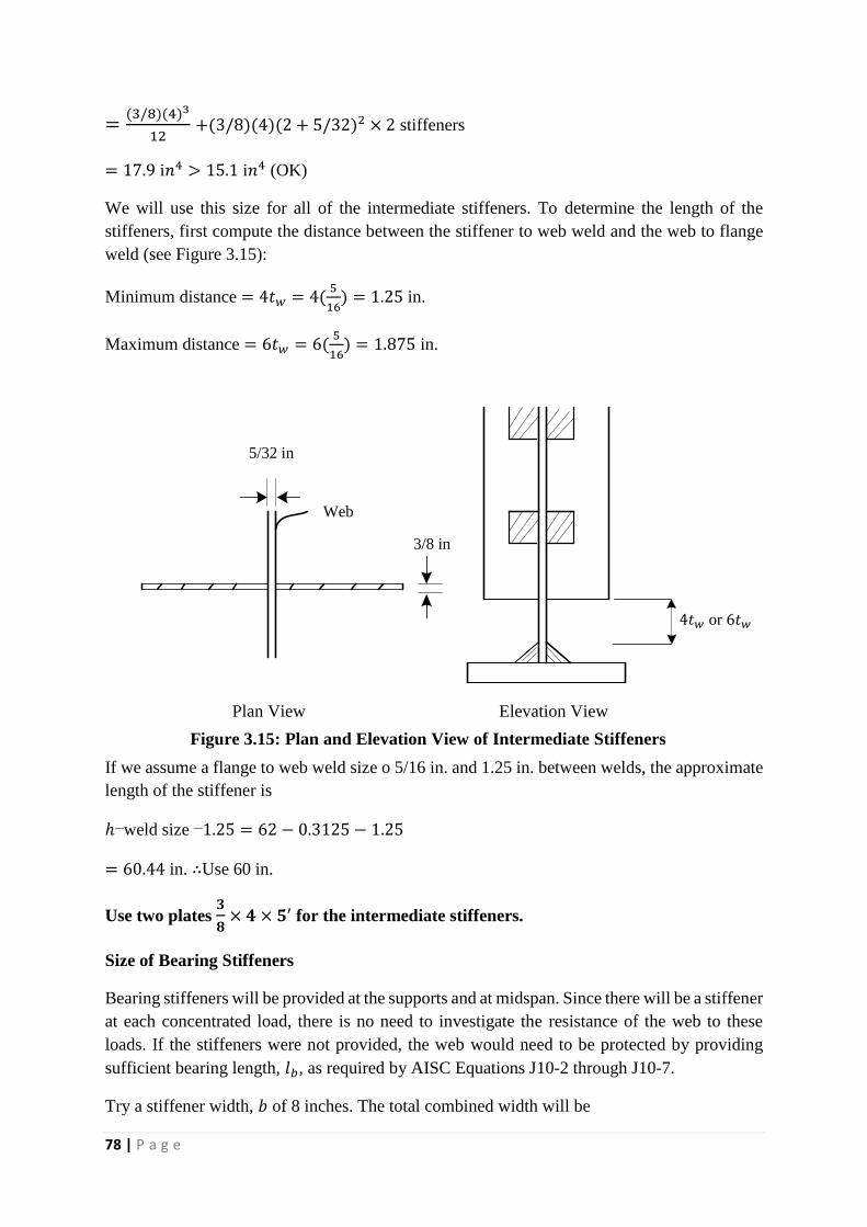
78 | P a g e
=(3/8)(4)3
12 +(3/8)(4)(2 + 5/32)2 × 2 stiffeners
= 17.9 i𝑛4 > 15.1 i𝑛4 (OK)
We will use this size for all of the intermediate stiffeners. To determine the length of the
stiffeners, first compute the distance between the stiffener to web weld and the web to flange
weld (see Figure 3.15):
Minimum distance = 4𝑡𝑤 = 4(5
16) = 1.25 in.
Maximum distance = 6𝑡𝑤 = 6(5
16) = 1.875 in.
If we assume a flange to web weld size o 5/16 in. and 1.25 in. between welds, the approximate
length of the stiffener is
ℎ−weld size −1.25 = 62 − 0.3125 − 1.25
= 60.44 in. ∴Use 60 in.
Use two plates 𝟑
𝟖 × 𝟒 × 𝟓′ for the intermediate stiffeners.
Size of Bearing Stiffeners
Bearing stiffeners will be provided at the supports and at midspan. Since there will be a stiffener
at each concentrated load, there is no need to investigate the resistance of the web to these
loads. If the stiffeners were not provided, the web would need to be protected by providing
sufficient bearing length, 𝑙𝑏, as required by AISC Equations J10-2 through J10-7.
Try a stiffener width, 𝑏 of 8 inches. The total combined width will be
Web
5/32 in
3/8 in
4𝑡𝑤 or 6𝑡𝑤
Plan View Elevation View
Figure 3.15: Plan and Elevation View of Intermediate Stiffeners

79 | P a g e
2(8) + 5/16 (the web thickness) = 16.31 inches, or slightly less than the flange width of 18
inches. From Equation-28
(𝑏
𝑡)𝑠7 ≤ 0.56√
𝐸
𝐹𝑦𝑠𝑡
𝑡 ≥𝑏
0.56√
𝐹𝑦𝑠𝑡
𝐸=
8
0.56√
36
29,000 = 0.503 𝑖𝑛.
Try two 3/4 × 8 stiffeners. Assume a 3/16 in. web to flange weld and a 1/2 in. cut-out in the
stiffener. Check the stiffener at the support.
11
22
8 in
0.75 in
7.5 in
0.75 in
8 in
Section 1-1
Section 2-2
The bearing strength is
𝑅𝑛 = 1.8𝐹𝑦𝐴𝑝𝑏 = 1.8(36)(0.75)(8 − 0.5) × 2 = 729.0 kips
𝜑𝑅𝑛 = 0.75(729.0) = 547 kips > 223.4 kips (OK)
Check the stiffener as a column.
The length of web acting with the stiffener plates to form a compression member is 12 times
the web thickness for an end stiffener (AISC J10.8). As shown in Figure 3.16, this length is
12(5/16) = 3.75 in. If we locate the stiffener centrally within this length, the point of support
12 𝑡𝑤
Figure 3.16: Bearing Stiffener at the Support
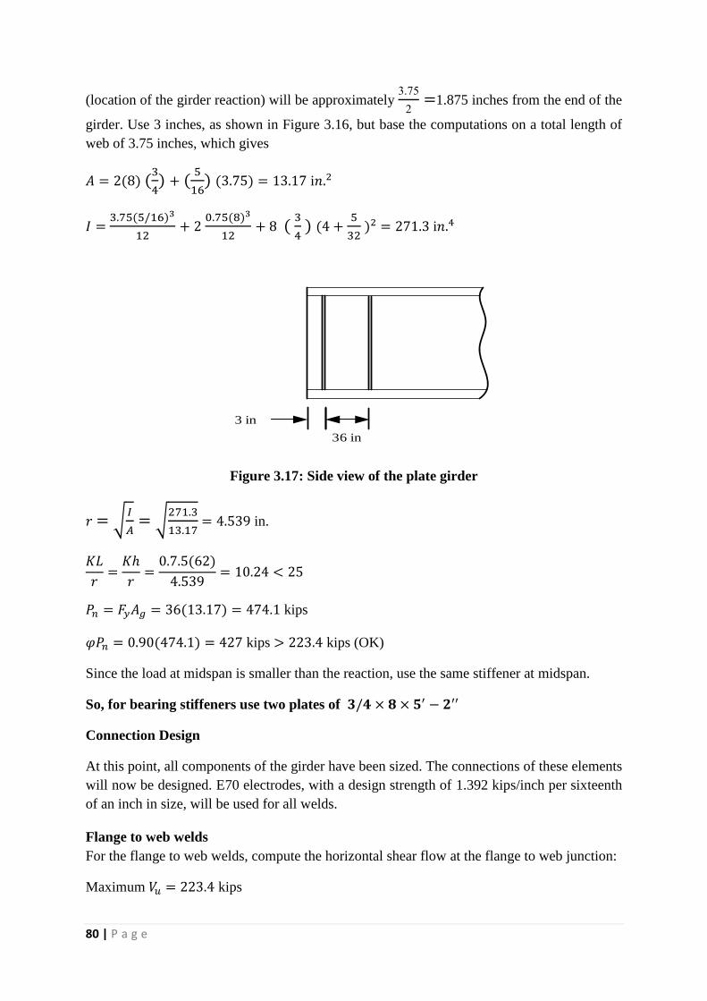
80 | P a g e
(location of the girder reaction) will be approximately 3.75
2=1.875 inches from the end of the
girder. Use 3 inches, as shown in Figure 3.16, but base the computations on a total length of
web of 3.75 inches, which gives
𝐴 = 2(8) (3
4) + (
5
16) (3.75) = 13.17 i𝑛.2
𝐼 = 3.75(5/16)3
12 + 2
0.75(8)3
12 + 8 (
3
4 ) (4 +
5
32 )2 = 271.3 i𝑛.4
36 in
3 in
Figure 3.17: Side view of the plate girder
𝑟 = √𝐼
𝐴= √
271.3
13.17 = 4.539 in.
𝐾𝐿
𝑟=
𝐾ℎ
𝑟=
0.7.5(62)
4.539= 10.24 < 25
𝑃𝑛 = 𝐹𝑦𝐴𝑔 = 36(13.17) = 474.1 kips
𝜑𝑃𝑛 = 0.90(474.1) = 427 kips > 223.4 kips (OK)
Since the load at midspan is smaller than the reaction, use the same stiffener at midspan.
So, for bearing stiffeners use two plates of 𝟑/𝟒 × 𝟖 × 𝟓′ − 𝟐′′
Connection Design
At this point, all components of the girder have been sized. The connections of these elements
will now be designed. E70 electrodes, with a design strength of 1.392 kips/inch per sixteenth
of an inch in size, will be used for all welds.
Flange to web welds
For the flange to web welds, compute the horizontal shear flow at the flange to web junction:
Maximum 𝑉𝑢 = 223.4 kips

81 | P a g e
𝑄 =flange area × �̅� (see Figure 3.11)
= 1.5(18)(31.75) = 857.2 i𝑛.3
𝐼𝑥 = 60,640 i𝑛.4
Maximum 𝑉𝑢𝑄
𝐼𝜒=
223.4(857.2)
60,640 = 3.158 kips/in.
For the plate thicknesses being welded, the minimum weld size, 𝑤 is 3/16 in. If intermittent
welds are used, their minimum length is
𝐿 min = 4 × 𝑤 ≥ 1.5 in.
= 4 (3
16) = 0.75 in. ∴ Use 1.5 in.
Try 3/16-in. × 1 12⁄ -in. fillet welds:
Weld shear strength: 𝜑𝑅𝑛 = 0.75(0.707𝑤𝐹𝑛𝑤)
Where, 𝐹𝑛𝑤 in a fillet weld is 0.6 times the tensile strength of the weld metal
∴ Weld shear strength per sixteenth of an inch: 𝜑𝑅𝑛 = 0.75(0.707𝑤𝐹𝑛𝑤)
= 0.75 (0.707) (1/16) (0.6×70) =1.392 kips/inch
∴ Capacity per inch = 1.392 × 3 sixteenths × 2 welds = 8.352 kips/in.
Check the capacity of the base metal (From AISC manual equations J4-3 and J4-4). The web
is the thinner of the connected parts and controls.
The shear yield design strength per unit length is
𝜑𝑅𝑛 = 1.0(0.6𝐹𝑦𝑡) = 0.6𝐹𝑦𝑡 for a one‐inch length
𝜑𝑅𝑛 = 0.6𝐹𝑦𝑡 = 0.6(36)(5
16) = 6.750𝑘𝑖𝑝𝑠/𝑖𝑛.
The base metal shear rupture strength per unit length is
𝜑𝑅𝑛 = 0.45𝐹𝑢𝑡
= 0.45(58)(5
16) = 8.156 kips/in.
The base metal shear strength is therefore 6.750 kips/in. < 8.352 kips/in.
Use a total weld capacity of 6.750 kips/in. The capacity of a 1.5 in. length of a pair of welds is
6.750(1.5) = 10.13 kips
(3.34)
(3.35)
(3.36)

82 | P a g e
To determine the spacing, let
10.13
𝑠=
𝑉𝑢𝑄
𝐼𝑥
where 𝑠 is the center-to-center spacing of the welds in inches and
𝑠 =10.13
𝑉𝑢𝑄/𝐼𝑥=
10.13
3.158 = 3.21 in.
Using a center-to-center spacing of 3 inches will give a clear spacing of 3 − 1.5 = 1.5 inches.
The AISC Specification refers to spacing of intermittent fillet welds in Section F13 and Section
E6.
𝑑 ≤ 0.75√𝐸
𝐹𝑦𝑡𝑓, but no greater than 12 in.
Adapting these limits to the present case yields
0.75√𝐸
𝐹𝑦𝑡𝑓 = 0.75√
29,000
36(1.5) = 31.9 in. > 12in.
The maximum permissible clear spacing is therefore 12 inches, and the required clear spacing
of 1.5 inches is satisfactory.
There is no minimum spacing given in the Specification, but the AISC publication, “Detailing
for Steel Construction,” (AISC, 2009) states that intermittent welds are more economical than
continuous welds only if the center to center spacing is more than twice the length of the weld.
In this example, the spacing is equal to twice the length, so either type could be used.
Although the 3-inch center to center spacing can be used for the entire length of the girder, an
increased spacing can be used where the shear is less than the maximum of 223.4 kips. Three
different spacings will be investigated:
1. The closest required spacing of 3 inches.
2. The maximum permissible center to center spacing of 12 + 1.5 = 13.5 in.
3. An intermediate spacing of 5 inches.
The 5-inch spacing can be used when
𝑉𝑢𝑄
𝐼𝑥=
10.13
𝑠 or 𝑉𝑢 =
10.13𝐼𝑥
𝑄𝑠=
10.13(60,640)
857.2(5) = 143.3 kips
Refer to Figure 3.12 and let 𝑥 be the distance from the left support, giving
𝑉u = 223.4 − 4.34𝑥 = 143.3 kips
∴ 𝑥 = 18.46 ft

83 | P a g e
The 13.5-inch spacing can be used when
𝑉𝑢 = 10.13𝐼𝑥
𝑄𝑠=
10.13(60,640)
857.2(13.5) = 53.08 kips
Figure 3.12, shows that the shear never gets this small, so the maximum spacing never controls.
Use 3/16-in. × 1 12⁄ in. fillet welds for the flange to web welds, spaced as shown in Figure
3.18.
30'-3"
74 spaces @ 3" = 18'-6"
28 spaces @ 5"
=11'-8"1"
Figure 3.18: Weld between Flange and web
For the intermediate stiffener welds:
Minimum weld size =3
16 in. (based on the web thickness of
5
16 in.)
Minimum length = 4(3
16) = 0.75 in. < 1.5 in. Use 1.5 in.
Use two welds per stiffener for a total of four. The capacity per inch for two 3/16 in. fillet
welds per stiffener plate is
1.392 × 3 × 2 = 8.352 kips/in.
Check the shear strength of the stiffener (the thinner of the two connected parts).
From Equation-35, the shear yield strength per unit length is
𝜑𝑅𝑛 = 0.6𝐹𝑦𝑡 = 0.6(36)( 1
4 ) = 5.400 kips/in.
From Equation-36, the base metal shear rupture strength per unit length is
𝜑𝑅𝑛 = 0.45𝐹𝑢𝑡 = 045(58)( 1
4 ) = 6.525 kips/in.
The base metal shear strength is therefore 5.400 kips/in. per stiffener. This is less than the shear
strength of two welds (using two welds for each plate), so use a weld strength of 5.400 kips/in.
For the two plates (four welds), use

84 | P a g e
5. 400 × 2 = 10.80 kips/in.
Proportioning the intermediate stiffeners by the AISC rules does not require the computation
of any forces, but a force must be transmitted from the stiffener to the web, and the connection
should be designed for this force. Basler (1961) recommends the use of a shear flow of
𝑓 = 0.045ℎ √𝐹𝑦
3
𝐸 kips/in.
𝑓 = 0.045ℎ√𝐹𝑦
3
𝐸= 0.045(62)√
(36)3
29,000= 3.539 kips/in.
Use intermittent welds. The capacity of a 1.5 in. length of the 4 welds is 1.5(10.80) =16.20 kips
Equating the shear strength per inch and the required strength gives
16.20
𝑠 = 3.539 kips/in. or 𝑠 = 4.58 in.
From AISC G2.2, the maximum clear spacing is 16 times the web thickness but no greater than
10 inches, or
16 𝑡𝑤 = 16(5
16) = 5 in.
Use a center to center spacing of 4 12 ⁄ inches, resulting in a clear spacing of
4. 5 − 1.5 = 3 in. < 5 in. (OK)
Use 3/16-in. × 1 12⁄ -in. fillet welds for intermediate stiffeners, spaced as shown in Figure 3.19.
Section
Figure 3.19: Weld between web and intermediate stiffener
For the bearing stiffener welds:
Minimum weld size =3
16 in. (based on the thickness 𝑡𝑤 =
5
16 in.)
Minimum length = 4(3
16) = 0.75 in. < 1.5 in. Use 1.5 in.
(3.37)
3/1
6-i
n.
×1
12⁄ -
in
fill
et w
eld
s @
4.5
”
c/c

85 | P a g e
Use two welds per stiffener for a total of four. The capacity per inch for two 3/16‐inch fillet
welds per stiffener plate is
1.392 × 3 × 2 = 8.352 kips/in.
Check the shear strength of the web. From the design of the flange to web welds, the base metal
shear strength is 6.750 kips/in. per stiffener. This is less than the shear strength of two welds
(using two welds for each plate), so use a weld strength of 6.750 kips/in.
For the two plates (four welds), use 6.750 × 2 = 13.50 kips/in.
The capacity of a 1.5 in. length of four welds is
1.5(13.50) = 20.25 kips
For the end bearing stiffener, the applied load per inch is
Reaction
Length avai1able for weld =
223.4
62‐2(0.5) = 3.662 kips/in
From 20. 25/𝑠 = 3.662 ∴ 𝑠 = 5.53 inches. (Note that a smaller weld spacing is required for
the intermediate stiffeners)
Use 3/16-in.× 1 12⁄ -in. fillet welds for all bearing stiffeners, spaced as shown in Figure 3.20.
Section
Figure 3.20: Weld between web and bearing stiffener
3/1
6-i
n.
×1
12⁄ -
in
fill
et w
eld
s @
5.5
”
c/c
86 | P a g e
References:
• American Institute of Steel Construction. 2011a. Steel Construction Manual. 14th ed.
Chicago. • Old trails arch bridge [Online Image], Retrieved December 17, 2017, from
https://bridgehunter.com/ca/san-bernardino/old-trails-arch/
• Segui, W.T., 2012. Steel design. Cengage Learning.
• Structural steel frame [Online Image], Retrieved December 28, 2017, from
http://www.girder-slab.com/features.asp
• Structural steel shapes [Online Image], Retrieved December 17, 2017, from
https://www.archtoolbox.com/materials-systems/metals/structsteelshapes.html
• Trenton through truss bridge [Online Image], 2008, Retrieved December 17, 2017,
from https://bridgehunter.com/ut/cache/5034C/

87 | P a g e
Appendix.
AISC, Plate Sizes
Note to tables I &II: the first length given obtainable from most, and usually from all, of the
mills rolling the given width. The second given is the maximum obtainable from any mill, and
such lengths are subject to substantial extras. For plates of large sizes, Designers should consult
fabricators regarding possibilities of fabrication, shipment and erection.
Table I: Plates (available sizes)
Length, in feet, of Universal Mill plates obtainable in the respective widths shown
Thickness,
inches
Width, Inches
6-12 13-20 21-26 27-30 31-36 37-42 43-46 47-48 49-58 59-
60 1
4
65-
80
60-
125
60-
125
60-
125
60-
125
40-
100
90-
100
90-
100 40-65 60-
3
8
65-
80
60-
125
60-
125
60-
125
60-
125
60-
125
90-
125
90-
125 80-90 70-
1
2
65-
80
60-
125
60-
125
60-
125
60-
125
60-
125
90-
125
90-
125
85-
110 60-
3
4
60-
80
60-
125
60-
125
60-
125
60-
125
55-
125
90-
125
90-
125
80-
120 40-
1 60-
80
60-
125
60-
125
60-
125
60-
125 40
90-
125
90-
125 70-95 40-
11
4
60-
75 8-125
48-
125
49-
125
49-
125
38-
125
90-
115 75-90 60-75 40-
11
2
40-
60
48-
120
46-
125
46-
125
45-
125
33-
105 90-95 65-90 50-75 35-
13
4
35-
60
41-
110
40-
125
40-
125
38-
110 28-90 80-90 55-90 45-55 30-
2 30-
60 36-90
35-
125
35-
110 34-95 24-75 70-90 45-90 40-45 25-

88 | P a g e
AISC, Plate Sizes
Table II: Plates (available sizes)
Length, in feet, of Universal Mill plates obtainable in the respective widths shown
Thickness,
inches
Width, Inches
24-
36
37-
48
49-
60
61-
78
79-
96
97-
114
115-
132
133-
150
151-
168
169-
186 3
4
40-
45
40-
50
40-
50
35-
55
30-
48
27-
38 21-30 × × ×
3
8
38-
50
40-
70
40-
70
35-
70
30-
65
30-
52 26-48 17-30 24- 21-
1
2
36-
50
40-
70
40-
70
35-
70
30-
70
30-
55 36-50 20-37 33- 27-
3
4
36-
50
37-
70
35-
70
35-
70
30-
70
30-
55 35-48 19-45 45- 39-
1 36-
50
34-
70
30-
70
32-
70
25-
66
25-
53 35-48 18-45 45- 41-
11
4
30-
50
30-
70
25-
70
25-
65
20-
60
20-
45 31-45 17-45 42- 38-
11
2
25-
40
30-
70
23-
60
21-
60
16-
56
15-
45 30-45 16-42 41- 33-
13
4
25-
40
30-
60
22-
52
18-
59
14-
50
12-
45 28-44 15-42 40- 31-
2 20-
35
25-
55
20-
49
16-
52
13-
47
11-
45 24-43 14-42 39- 29-
Source: American Institute of steel construction (AISC), 9th edition, Page 59.
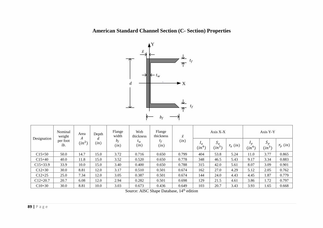
89 | P a g e
American Standard Channel Section (C- Section) Properties
X`
Y
Designation
Nominal
weight
per foot
𝑙𝑏.
Area
𝐴
(𝑖𝑛2)
Depth
𝑑
(𝑖𝑛)
Flange
width
𝑏𝑓
(𝑖𝑛)
Web
thickness
𝑡𝑤
(𝑖𝑛)
Flange
thickness
𝑡𝑓
(𝑖𝑛)
�̅�
(𝑖𝑛)
Axis X-X Axis Y-Y
𝐼𝑥 (𝑖𝑛4)
𝑆𝑥 (𝑖𝑛3)
𝑟𝑥 (𝑖𝑛) 𝐼𝑦
(𝑖𝑛4)
𝑆𝑦
(𝑖𝑛3) 𝑟𝑦 (𝑖𝑛)
C15×50 50.0 14.7 15.0 3.72 0.716 0.650 0.799 404 53.8 5.24 11.0 3.77 0.865
C15×40 40.0 11.8 15.0 3.52 0.520 0.650 0.778 348 46.5 5.43 9.17 3.34 0.883
C15×33.9 33.9 10.0 15.0 3.40 0.400 0.650 0.788 315 42.0 5.61 8.07 3.09 0.901
C12×30 30.0 8.81 12.0 3.17 0.510 0.501 0.674 162 27.0 4.29 5.12 2.05 0.762
C12×25 25.0 7.34 12.0 3.05 0.387 0.501 0.674 144 24.0 4.43 4.45 1.87 0.779
C12×20.7 20.7 6.08 12.0 2.94 0.282 0.501 0.698 129 21.5 4.61 3.86 1.72 0.797
C10×30 30.0 8.81 10.0 3.03 0.673 0.436 0.649 103 20.7 3.43 3.93 1.65 0.668
Source: AISC Shape Database, 14th edition
𝑡𝑓
𝑡𝑓
𝑡𝑤
𝑏𝑓
𝑑
�̅�

90 | P a g e
Designation
Nominal
weight
per foot
𝑙𝑏.
Area
𝐴
(𝑖𝑛2)
Depth
𝑑
(𝑖𝑛)
Flange
width
𝑏𝑓
(𝑖𝑛)
Web
thickness
𝑡𝑤
(𝑖𝑛)
Flange
thickness
𝑡𝑓
(𝑖𝑛)
�̅�
(𝑖𝑛)
Axis X-X Axis Y-Y
𝐼𝑥 (𝑖𝑛4)
𝑆𝑥 (𝑖𝑛3)
𝑟𝑥 (𝑖𝑛) 𝐼𝑦
(𝑖𝑛4)
𝑆𝑦
(𝑖𝑛3) 𝑟𝑦 (𝑖𝑛)
C10×25 25.0 7.35 10.0 2.89 0.526 0.436 0.617 91.1 18.2 3.52 3.34 1.47 0.675
C10×20 20.0 5.87 10.0 2.74 0.379 0.436 0.606 78.9 15.8 3.67 2.80 1.31 0.690
C10×15.3 15.3 4.48 10.0 2.60 0.240 0.436 0.634 67.3 13.5 3.88 2.27 1.15 0.711
C9×20 20.0 5.87 9.00 2.65 0.448 0.413 0.583 60.9 13.5 3.22 2.41 1.17 0.640
C9×15 15.0 4.40 9.00 2.49 0.285 0.413 0.586 51.0 11.3 3.40 1.91 1.01 0.659
C9×13.4 13.4 3.94 9.00 2.43 0.233 0.413 0.601 47.8 10.6 3.48 1.75 0.954 0.666
C8×18.75 18.75 5.51 8.00 2.53 0.487 0.390 0.565 43.9 11.0 2.82 1.97 1.01 0.598
C8×13.75 13.75 4.03 8.00 2.34 0.303 0.390 0.554 36.1 9.02 2.99 1.52 0.848 0.613
C8×11.5 11.5 3.37 8.00 2.26 0.220 0.390 0.572 32.5 8.14 3.11 1.31 0.775 0.623
C7×14.75 14.75 4.33 7.00 2.30 0.419 0.366 0.532 27.2 7.78 2.51 1.37 0.772 0.561
C7×12.25 12.25 3.59 7.00 2.19 0.314 0.366 0.525 24.2 6.92 2.59 1.16 0.696 0.568
C7×9.8 9.80 2.87 7.00 2.09 0.210 0.366 0.541 21.2 6.07 2.72 0.957 0.617 0.578
C6×13 13.0 3.82 6.00 2.16 0.437 0.343 0.514 17.3 5.78 2.13 1.05 0.638 0.524
C6×10.5 10.5 3.07 6.00 2.03 0.314 0.343 0.500 15.1 5.04 2.22 0.860 0.561 0.529
C6×8.2 8.20 2.39 6.00 1.92 0.200 0.343 0.512 13.1 4.35 2.34 0.687 0.488 0.536
C5×9 9.00 2.64 5.00 1.89 0.325 0.320 0.478 8.89 3.56 1.84 0.624 0.444 0.486
C5×6.7 6.70 1.97 5.00 1.75 0.190 0.320 0.484 7.48 2.99 1.95 0.470 0.372 0.489
C4×7.25 7.25 2.13 4.00 1.72 0.321 0.296 0.459 4.58 2.29 1.47 0.425 0.337 0.447
C4×6.25 6.25 1.77 4.00 1.65 0.247 0.272 0.435 4.00 2.00 1.50 0.345 0.284 0.441
C4×5.4 5.40 1.58 4.00 1.58 0.184 0.296 0.457 3.85 1.92 1.56 0.312 0.277 0.444
C4×4.5 4.50 1.38 4.00 1.58 0.125 0.296 0.493 3.65 1.83 1.63 0.289 0.265 0.457
C3×6 6.00 1.76 3.00 1.60 0.356 0.273 0.455 2.07 1.38 1.09 0.300 0.263 0.413
C3×5 5.00 1.47 3.00 1.50 0.258 0.273 0.439 1.85 1.23 1.12 0.241 0.228 0.405
C3×4.1 4.10 1.20 3.00 1.41 0.170 0.273 0.437 1.65 1.10 1.18 0.191 0.196 0.398
C3×3.5 3.50 1.09 3.00 1.37 0.132 0.273 0.443 1.57 1.04 1.20 0.169 0.182 0.394
Source: AISC Shape Database, 14th edition

91 | P a g e
American Standard Angle Section (L- Section) Properties
Short Leg
Lo
ng
Leg
X
Y
Zα
Designation
Nominal
weight per
foot
𝑙𝑏.
Area
𝐴
(𝑖𝑛2)
�̅�
(𝑖𝑛)
�̅�
(𝑖𝑛)
Axis X-X Axis Y-Y Axis Z-Z
𝐼𝑥 (𝑖𝑛4)
𝑆𝑥 (𝑖𝑛3)
𝑟𝑥 (𝑖𝑛)
𝐼𝑦
(𝑖𝑛4)
𝑆𝑦
(𝑖𝑛3)
𝑟𝑦
(𝑖𝑛) 𝑟𝑧 (𝑖𝑛) tan 𝛼
L8×8×1-1/8 56.9 16.8 2.40 2.40 98.1 17.5 2.41 98.1 17.5 2.41 1.56 1.00
L8×8×1 51.0 15.1 2.36 2.36 89.1 15.8 2.43 89.1 15.8 2.43 1.56 1.00
L8×8×7/8 45.0 13.3 2.31 2.31 79.7 14.0 2.45 79.7 14.0 2.45 1.57 1.00
L8×8×3/4 38.9 11.5 2.26 2.26 69.9 12.2 2.46 69.9 12.2 2.46 1.57 1.00
L8×8×5/8 32.7 9.69 2.21 2.21 59.6 10.3 2.48 59.6 10.3 2.48 1.58 1.00
L8×8×9/16 29.6 8.77 2.19 2.19 54.2 9.33 2.49 54.2 9.33 2.49 1.58 1.00
L8×8×1/2 26.4 7.84 2.17 2.17 48.8 8.36 2.49 48.8 8.36 2.49 1.59 1.00
L8×6×1 44.2 13.1 1.65 2.65 80.9 15.1 2.49 38.8 8.92 1.72 1.28 0.542
L8×6×7/8 39.1 11.5 1.60 2.60 72.4 13.4 2.50 34.9 7.94 1.74 1.28 0.546
L8×6×3/4 33.8 9.99 1.56 2.55 63.5 11.7 2.52 30.8 6.92 1.75 1.29 0.550
L8×6×5/8 28.5 8.41 1.51 2.50 54.2 9.86 2.54 26.4 5.88 1.77 1.29 0.554
L8×6×9/16 25.7 7.61 1.49 2.48 49.4 8.94 2.55 24.1 5.34 1.78 1.30 0.556
Source: AISC Shape Database, 14th edition

92 | P a g e
Designation
Nominal
weight per
foot
𝑙𝑏.
Area
𝐴
(𝑖𝑛2)
�̅�
(𝑖𝑛)
�̅�
(𝑖𝑛)
Axis X-X Axis Y-Y Axis Z-Z
𝐼𝑥 (𝑖𝑛4)
𝑆𝑥 (𝑖𝑛3)
𝑟𝑥
(𝑖𝑛)
𝐼𝑦
(𝑖𝑛4)
𝑆𝑦
(𝑖𝑛3)
𝑟𝑦
(𝑖𝑛) 𝑟𝑧 (𝑖𝑛) tan 𝛼
L8×6×1/2 23.0 6.80 1.46 2.46 44.4 8.01 2.55 21.7 4.79 1.79 1.30 0.557
L8×6×7/16 20.2 5.99 1.44 2.43 39.3 7.06 2.56 19.3 4.23 1.80 1.31 0.559
L8×4×1 37.4 11.1 1.04 3.03 69.7 14.0 2.51 11.6 3.94 1.03 0.844 0.247
L8×4×7/8 33.1 9.79 0.997 2.99 62.6 12.5 2.53 10.5 3.51 1.04 0.846 0.252
L8×4×3/4 28.7 8.49 0.949 2.94 55.0 10.9 2.55 9.37 3.07 1.05 0.850 0.257
L8×4×5/8 24.2 7.16 0.902 2.89 47.0 9.20 2.56 8.11 2.62 1.06 0.856 0.262
L8×4×9/16 21.9 6.49 0.878 2.86 42.9 8.34 2.57 7.44 2.38 1.07 0.859 0.264
L8×4×1/2 19.6 5.80 0.854 2.84 38.6 7.48 2.58 6.75 2.15 1.08 0.863 0.266
L8×4×7/16 17.2 5.11 0.829 2.81 34.2 6.59 2.59 6.03 1.90 1.09 0.867 0.268
L7×4×3/4 26.2 7.74 1.00 2.50 37.8 8.39 2.21 9.00 3.01 1.08 0.855 0.324
L7×4×5/8 22.1 6.50 0.958 2.45 32.4 7.12 2.23 7.79 2.56 1.10 0.860 0.329
L7×4×1/2 17.9 5.26 0.910 2.40 26.6 5.79 2.25 6.48 2.10 1.11 0.866 0.334
L7×4×7/16 15.7 4.63 0.886 2.38 23.6 5.11 2.26 5.79 1.86 1.12 0.869 0.337
L7×4×3/8 13.6 4.00 0.861 2.35 20.5 4.42 2.27 5.06 1.61 1.12 0.873 0.339
L6×6×1 37.4 11.0 1.86 1.86 35.4 8.55 1.79 35.4 8.55 1.79 1.17 1.00
L6×6×7/8 33.1 9.75 1.81 1.81 31.9 7.61 1.81 31.9 7.61 1.81 1.17 1.00
L6×6×3/4 28.7 8.46 1.77 1.77 28.1 6.64 1.82 28.1 6.64 1.82 1.17 1.00
L6×6×5/8 24.2 7.13 1.72 1.72 24.1 5.64 1.84 24.1 5.64 1.84 1.17 1.00
L6×6×9/16 21.9 6.45 1.70 1.70 22.0 5.12 1.85 22.0 5.12 1.85 1.18 1.00
L6×6×1/2 19.6 5.77 1.67 1.67 19.9 4.59 1.86 19.9 4.59 1.86 1.18 1.00
L6×6×7/16 17.2 5.08 1.65 1.65 17.6 4.06 1.86 17.6 4.06 1.86 1.18 1.00
L6×6×3/8 14.9 4.38 1.62 1.62 15.4 3.51 1.87 15.4 3.51 1.87 1.19 1.00
L6×6×5/16 12.4 3.67 1.60 1.60 13.0 2.95 1.88 13.0 2.95 1.88 1.19 1.00
L6×4×7/8 27.2 8.00 1.12 2.12 27.7 7.13 1.86 9.70 3.37 1.10 0.854 0.421
L6×4×3/4 23.6 6.94 1.07 2.07 24.5 6.23 1.88 8.63 2.95 1.12 0.856 0.428
L6×4×5/8 20.0 5.86 1.03 2.03 21.0 5.29 1.89 7.48 2.52 1.13 0.859 0.435
L6×4×9/16 18.1 5.31 1.00 2.00 19.2 4.81 1.90 6.86 2.29 1.14 0.861 0.438
Source: AISC Shape Database, 14th edition

93 | P a g e
Designation
Nominal
weight per
foot
𝑙𝑏.
Area
𝐴
(𝑖𝑛2)
�̅�
(𝑖𝑛)
�̅�
(𝑖𝑛)
Axis X-X Axis Y-Y Axis Z-Z
𝐼𝑥 (𝑖𝑛4)
𝑆𝑥 (𝑖𝑛3)
𝑟𝑥
(𝑖𝑛)
𝐼𝑦
(𝑖𝑛4)
𝑆𝑦
(𝑖𝑛3)
𝑟𝑦
(𝑖𝑛) 𝑟𝑧 (𝑖𝑛) tan 𝛼
L6×4×1/2 16.2 4.75 0.981 1.98 17.3 4.31 1.91 6.22 2.06 1.14 0.864 0.440
L6×4×7/16 14.3 4.18 0.957 1.95 15.4 3.81 1.92 5.56 1.83 1.15 0.867 0.443
L6×4×3/8 12.3 3.61 0.933 1.93 13.4 3.30 1.93 4.86 1.58 1.16 0.870 0.446
L6×4×5/16 10.3 3.03 0.908 1.90 11.4 2.77 1.94 4.13 1.34 1.17 0.874 0.449
L6×3-1/2×1/2 15.3 4.50 0.829 2.07 16.6 4.23 1.92 4.24 1.59 0.968 0.756 0.343
L6×3-1/2×3/8 11.7 3.44 0.781 2.02 12.9 3.23 1.93 3.33 1.22 0.984 0.763 0.349
L6×3-1/2×5/16 9.80 2.89 0.756 2.00 10.9 2.72 1.94 2.84 1.03 0.991 0.767 0.352
L5×5×7/8 27.2 8.00 1.56 1.56 17.8 5.16 1.49 17.8 5.16 1.49 0.971 1.00
L5×5×3/4 23.6 6.98 1.52 1.52 15.7 4.52 1.50 15.7 4.52 1.50 0.972 1.00
L5×5×5/8 20.0 5.90 1.47 1.47 13.6 3.85 1.52 13.6 3.85 1.52 0.975 1.00
L5×5×1/2 16.2 4.79 1.42 1.42 11.3 3.15 1.53 11.3 3.15 1.53 0.980 1.00
L5×5×7/16 14.3 4.22 1.40 1.40 10.0 2.78 1.54 10.0 2.78 1.54 0.983 1.00
L5×5×3/8 12.3 3.65 1.37 1.37 8.76 2.41 1.55 8.76 2.41 1.55 0.986 1.00
L5×5×5/16 10.3 3.07 1.35 1.35 7.44 2.04 1.56 7.44 2.04 1.56 0.990 1.00
L5×3-1/2×3/4 19.8 5.85 0.993 1.74 13.9 4.26 1.55 5.52 2.20 0.974 0.744 0.464
L5×3-1/2×5/8 16.8 4.93 0.947 1.69 12.0 3.63 1.56 4.80 1.88 0.987 0.746 0.472
L5×3-1/2×1/2 13.6 4.00 0.901 1.65 10.0 2.97 1.58 4.02 1.55 1.00 0.750 0.479
L5×3-1/2×3/8 10.4 3.05 0.854 1.60 7.75 2.28 1.59 3.15 1.19 1.02 0.755 0.485
L5×3-1/2×5/16 8.70 2.56 0.829 1.57 6.58 1.92 1.60 2.69 1.01 1.02 0.758 0.489
L5×3-1/2×1/4 7.00 2.07 0.804 1.55 5.36 1.55 1.61 2.20 0.816 1.03 0.761 0.491
L5×3×1/2 12.8 3.75 0.746 1.74 9.43 2.89 1.58 2.55 1.13 0.824 0.642 0.357
L5×3×7/16 11.3 3.31 0.722 1.72 8.41 2.56 1.59 2.29 1.00 0.831 0.644 0.361
L5×3×3/8 9.80 2.86 0.698 1.69 7.35 2.22 1.60 2.01 0.874 0.838 0.646 0.364
L5×3×5/16 8.20 2.41 0.673 1.67 6.24 1.87 1.61 1.72 0.739 0.846 0.649 0.368
L5×3×1/4 6.60 1.94 0.648 1.64 5.09 1.51 1.62 1.41 0.600 0.853 0.652 0.371
L4×4×3/4 18.5 5.44 1.27 1.27 7.62 2.79 1.18 7.62 2.79 1.18 0.774 1.00
L4×4×5/8 15.7 4.61 1.22 1.22 6.62 2.38 1.20 6.62 2.38 1.20 0.774 1.00
Source: AISC Shape Database, 14th edition

94 | P a g e
Designation
Nominal
weight per
foot
𝑙𝑏.
Area
𝐴
(𝑖𝑛2)
�̅�
(𝑖𝑛)
�̅�
(𝑖𝑛)
Axis X-X Axis Y-Y Axis Z-Z
𝐼𝑥 (𝑖𝑛4)
𝑆𝑥 (𝑖𝑛3)
𝑟𝑥
(𝑖𝑛)
𝐼𝑦
(𝑖𝑛4)
𝑆𝑦
(𝑖𝑛3)
𝑟𝑦
(𝑖𝑛) 𝑟𝑧 (𝑖𝑛) tan 𝛼
L4×4×1/2 12.8 3.75 1.18 1.18 5.52 1.96 1.21 5.52 1.96 1.21 0.776 1.00
L4×4×7/16 11.3 3.30 1.15 1.15 4.93 1.73 1.22 4.93 1.73 1.22 0.777 1.00
L4×4×3/8 9.80 2.86 1.13 1.13 4.32 1.50 1.23 4.32 1.50 1.23 0.779 1.00
L4×4×5/16 8.20 2.40 1.11 1.11 3.67 1.27 1.24 3.67 1.27 1.24 0.781 1.00
L4×4×1/4 6.60 1.93 1.08 1.08 3.00 1.03 1.25 3.00 1.03 1.25 0.783 1.00
L4×3-1/2×1/2 11.9 3.50 0.994 1.24 5.30 1.92 1.23 3.76 1.50 1.04 0.716 0.750
L4×3-1/2×3/8 9.10 2.68 0.947 1.20 4.15 1.48 1.25 2.96 1.16 1.05 0.719 0.755
L4×3-1/2×5/16 7.70 2.25 0.923 1.17 3.53 1.25 1.25 2.52 0.980 1.06 0.721 0.757
L4×3-1/2×1/4 6.20 1.82 0.897 1.14 2.89 1.01 1.26 2.07 0.794 1.07 0.723 0.759
L4×3×5/8 13.6 3.99 0.867 1.37 6.01 2.28 1.23 2.85 1.34 0.845 0.631 0.534
L4×3×1/2 11.1 3.25 0.822 1.32 5.02 1.87 1.24 2.40 1.10 0.858 0.633 0.542
L4×3×3/8 8.50 2.49 0.775 1.27 3.94 1.44 1.26 1.89 0.851 0.873 0.636 0.551
L4×3×5/16 7.20 2.09 0.750 1.25 3.36 1.22 1.27 1.62 0.721 0.880 0.638 0.554
L4×3×1/4 5.80 1.69 0.725 1.22 2.75 0.988 1.27 1.33 0.585 0.887 0.639 0.558
L3-1/2×3-1/2×1/2 11.1 3.25 1.05 1.05 3.63 1.48 1.05 3.63 1.48 1.05 0.679 1.00
L3-1/2×3-1/2×7/16 9.80 2.89 1.03 1.03 3.25 1.32 1.06 3.25 1.32 1.06 0.681 1.00
L3-1/2×3-1/2×3/8 8.50 2.50 1.00 1.00 2.86 1.15 1.07 2.86 1.15 1.07 0.683 1.00
L3-1/2×3-1/2×5/16 7.20 2.10 0.979 0.979 2.44 0.969 1.08 2.44 0.969 1.08 0.685 1.00
L3-1/2×3-1/2×1/4 5.80 1.70 0.954 0.954 2.00 0.787 1.09 2.00 0.787 1.09 0.688 1.00
L3-1/2×3×1/2 10.2 3.02 0.869 1.12 3.45 1.45 1.07 2.32 1.09 0.877 0.618 0.713
L3-1/2×3×7/16 9.10 2.67 0.846 1.09 3.10 1.29 1.08 2.09 0.971 0.885 0.620 0.717
L3-1/2×3×3/8 7.90 2.32 0.823 1.07 2.73 1.12 1.09 1.84 0.847 0.892 0.622 0.720
L3-1/2×3×5/16 6.60 1.95 0.798 1.05 2.33 0.951 1.09 1.58 0.718 0.900 0.624 0.722
L3-1/2×3×1/4 5.40 1.58 0.773 1.02 1.92 0.773 1.10 1.30 0.585 0.908 0.628 0.725
L3-1/2×2-1/2×1/2 9.40 2.77 0.701 1.20 3.24 1.41 1.08 1.36 0.756 0.701 0.532 0.485
L3-1/2×2-1/2×3/8 7.20 2.12 0.655 1.15 2.56 1.09 1.10 1.09 0.589 0.716 0.535 0.495
L3-1/2×2-1/2×5/16 6.10 1.79 0.632 1.13 2.20 0.925 1.11 0.937 0.501 0.723 0.538 0.500
Source: AISC Shape Database, 14th edition

95 | P a g e
Designation
Nominal
weight per
foot
𝑙𝑏.
Area
𝐴
(𝑖𝑛2)
�̅�
(𝑖𝑛)
�̅�
(𝑖𝑛)
Axis X-X Axis Y-Y Axis Z-Z
𝐼𝑥 (𝑖𝑛4)
𝑆𝑥 (𝑖𝑛3)
𝑟𝑥
(𝑖𝑛)
𝐼𝑦
(𝑖𝑛4)
𝑆𝑦
(𝑖𝑛3)
𝑟𝑦
(𝑖𝑛) 𝑟𝑧 (𝑖𝑛) tan 𝛼
L3-1/2×2-1/2×1/4 4.90 1.45 0.607 1.10 1.81 0.753 1.12 0.775 0.410 0.731 0.541 0.504
L3×3×1/2 9.40 2.76 0.929 0.929 2.20 1.06 0.895 2.20 1.06 0.895 0.580 1.00
L3×3×7/16 8.30 2.43 0.907 0.907 1.98 0.946 0.903 1.98 0.946 0.903 0.580 1.00
L3×3×3/8 7.20 2.11 0.884 0.884 1.75 0.825 0.910 1.75 0.825 0.910 0.581 1.00
L3×3×5/16 6.10 1.78 0.860 0.860 1.50 0.699 0.918 1.50 0.699 0.918 0.583 1.00
L3×3×1/4 4.90 1.44 0.836 0.836 1.23 0.569 0.926 1.23 0.569 0.926 0.585 1.00
L3×3×3/16 3.71 1.09 0.812 0.812 0.948 0.433 0.933 0.948 0.433 0.933 0.586 1.00
L3×2-1/2×1/2 8.50 2.50 0.746 0.995 2.07 1.03 0.910 1.29 0.736 0.718 0.516 0.666
L3×2-1/2×7/16 7.60 2.22 0.724 0.972 1.87 0.921 0.917 1.17 0.656 0.724 0.516 0.671
L3×2-1/2×3/8 6.60 1.93 0.701 0.949 1.65 0.803 0.924 1.03 0.573 0.731 0.517 0.675
L3×2-1/2×5/16 5.60 1.63 0.677 0.925 1.41 0.681 0.932 0.888 0.487 0.739 0.518 0.679
L3×2-1/2×1/4 4.50 1.32 0.653 0.900 1.16 0.555 0.940 0.734 0.397 0.746 0.520 0.683
L3×2-1/2×3/16 3.39 1.00 0.627 0.874 0.899 0.423 0.947 0.568 0.303 0.753 0.521 0.687
L3×2×1/2 7.70 2.26 0.580 1.08 1.92 1.00 0.922 0.667 0.470 0.543 0.425 0.413
L3×2×3/8 5.90 1.75 0.535 1.03 1.54 0.779 0.937 0.539 0.368 0.555 0.426 0.426
L3×2×5/16 5.00 1.48 0.511 1.01 1.32 0.662 0.945 0.467 0.314 0.562 0.428 0.432
L3×2×1/4 4.10 1.20 0.487 0.980 1.09 0.541 0.953 0.390 0.258 0.569 0.431 0.437
L3×2×3/16 3.07 0.917 0.462 0.952 0.847 0.414 0.961 0.305 0.198 0.577 0.435 0.442
L2-1/2×2-1/2×1/2 7.70 2.26 0.803 0.803 1.22 0.716 0.735 1.22 0.716 0.735 0.481 1.00
L2-1/2×2-1/2×3/8 5.90 1.73 0.758 0.758 0.972 0.558 0.749 0.972 0.558 0.749 0.481 1.00
L2-1/2×2-1/2×5/16 5.00 1.46 0.735 0.735 0.837 0.474 0.756 0.837 0.474 0.756 0.481 1.00
L2-1/2×2-1/2×1/4 4.10 1.19 0.711 0.711 0.692 0.387 0.764 0.692 0.387 0.764 0.482 1.00
L2-1/2×2-1/2×3/16 3.07 0.901 0.687 0.687 0.535 0.295 0.771 0.535 0.295 0.771 0.482 1.00
L2-1/2×2×3/8 5.30 1.55 0.578 0.826 0.914 0.546 0.766 0.513 0.361 0.574 0.419 0.612
L2-1/2×2×5/16 4.50 1.32 0.555 0.803 0.790 0.465 0.774 0.446 0.309 0.581 0.420 0.618
L2-1/2×2×1/4 3.62 1.07 0.532 0.779 0.656 0.381 0.782 0.372 0.253 0.589 0.423 0.624
L2-1/2×2×3/16 2.75 0.818 0.508 0.754 0.511 0.293 0.790 0.292 0.195 0.597 0.426 0.628
Source: AISC Shape Database, 14th edition

96 | P a g e
Designation
Nominal
weight per
foot
𝑙𝑏.
Area
𝐴
(𝑖𝑛2)
�̅�
(𝑖𝑛)
�̅�
(𝑖𝑛)
Axis X-X Axis Y-Y Axis Z-Z
𝐼𝑥 (𝑖𝑛4)
𝑆𝑥 (𝑖𝑛3)
𝑟𝑥
(𝑖𝑛)
𝐼𝑦
(𝑖𝑛4)
𝑆𝑦
(𝑖𝑛3)
𝑟𝑦
(𝑖𝑛) 𝑟𝑧 (𝑖𝑛) tan 𝛼
L2-1/2×1-1/2×1/4 3.19 0.947 0.372 0.866 0.594 0.364 0.792 0.160 0.142 0.411 0.321 0.354
L2-1/2×1-1/2×3/16 2.44 0.724 0.347 0.839 0.464 0.280 0.801 0.126 0.110 0.418 0.324 0.360
L2×2×3/8 4.70 1.37 0.632 0.632 0.476 0.348 0.591 0.476 0.348 0.591 0.386 1.00
L2×2×5/16 3.92 1.16 0.609 0.609 0.414 0.298 0.598 0.414 0.298 0.598 0.386 1.00
L2×2×1/4 3.19 0.944 0.586 0.586 0.346 0.244 0.605 0.346 0.244 0.605 0.387 1.00
L2×2×3/16 2.44 0.722 0.561 0.561 0.271 0.188 0.612 0.271 0.188 0.612 0.389 1.00
L2×2×1/8 1.65 0.491 0.534 0.534 0.189 0.129 0.620 0.189 0.129 0.620 0.391 1.00
Source: AISC Shape Database, 14th edition

97 | P a g e
Basic Wind Speeds for Selected Locations in Bangladesh
(BNBC-1993 Table 6.2.8)
Location Basic Wind
Speed (km/h) Location
Basic Wind
Speed
(km/h)
Angarpota
Bagerhat
Bandarban
Barguna
Barisal
Bhola
Bogra
Brahmanbaria
Chandpur
Chapai Nawabganj
Chittagong
Chuadanga
Comilla
Cox’s Bazar
Dahagram
Dhaka
Dinajpur
Faridpur
Feni
Gaibandha
Gazipur
Gopalganj
Habiganj
Hatiya
Ishurdi
Joypurhat
Jamalpur
Jessore
Jhalakati
Jhenaidah
Khagrachhari
Khulna
Kutubdia
Kishoreganj
Kurigram
Kushtia
Lakshmipur
150
252
200
260
256
225
198
180
160
130
260
198
196
260
150
210
130
202
205
210
215
242
172
260
225
180
180
205
260
208
180
238
260
207
210
215
162
Lalmonirhat
Madaripur
Magura
Manikganj
Meherpur
Maheshkhali
Moulvibazar
Munshiganj
Mymensingh
Naogaon
Narail
Narayanganj
Narsinghdi
Natore
Netrokona
Nilphamari
Noakhali
Pabna
Panchagarh
Patuakhali
Pirojpur
Rajbari
Rajshahi
Rangamati
Rangpur
Satkhira
Shariatpur
Sherpur
Sirajganj
Srimangal
St. Martin’s Island
Sunamganj
Sylhet
Sandwip
Tangail
Teknaf
Thakurgaon
204
220
208
185
185
260
168
184
217
175
222
195
190
198
210
140
184
202
130
260
260
188
155
180
209
183
198
200
160
160
260
195
195
260
160
260
130

98 | P a g e
Structure Importance Coefficients, 𝑪𝑰 for Wind Loads
(BNBC-1993 Table 6.2.9)
Structure Importance
Category
Structure Importance
Coefficient, 𝑪𝑰
Essential facilities 1.25
Hazardous facilities 1.25
Special occupancy structures 1.00
Standard occupancy structures 1.00
Low-risk structures 0.80
Exposure (Defined by BNBC-1993)
Exposure: This refers to the conditions of the terrain surrounding the building site. The terrain
exposure in which a building or structure is to be sited shall be assessed as being one of the
following categories:
• Exposure A: Urban and sub-urban areas, industrial area, wooded areas, hilly or other
terrain covering at least 20% of the area with obstructions of 6 meters or more in height
and extending from the site at least 500 meters or 10 times the height of the structure,
whichever is greater.
• Exposure B: Open terrain with scattered obstructions having heights generally less
than 10 meters extending 800 meters or more from the site in any full quadrant. This
category includes air fields, open park lands, sparsely built-up outskirts of towns, flat
open country and grasslands.
• Exposure C: Flat and un-obstructed open terrain, coastal areas and riversides facing
large bodies of water, over 1.5 km or more in width. Exposure C extends inland from
the shoreline 400 meter or 10 times the height of the structure, whichever is greater.

99 | P a g e
Combined Height and Exposure Coefficient, 𝑪𝒛
Height above
ground level, z
(meter)
Exposure A Exposure B Exposure C
0-4.5
6.0
9.0
12.0
15.0
18.0
21.0
24.0
27.0
30.0
35.0
40.0
45.0
50.0
60.0
70.0
80.0
90.0
100.0
110.0
120.0
130.0
140.0
150.0
160.0
170.0
180.0
190.0
200.0
220.0
240.0
260.0
280.0
300.0
0.368
0.415
0.497
0.565
0.624
0.677
0.725
0.769
0.810
0.849
0.909
0.965
1.017
1.065
1.155
1.237
1.313
1.383
1.450
1.513
1.572
1.629
1.684
1.736
1.787
1.835
1.883
1.928
1.973
2.058
2.139
2.217
2.910
2.362
0.801
0.866
0.972
1.055
1.125
1.185
1.238
1.286
1.330
1.371
1.433
1.488
1.539
1.586
1.671
1.746
1.814
1.876
1.934
1.987
2.037
2.084
2.129
2.171
2.212
2.250
2.287
2.323
2.357
2.422
2.483
2.541
2.595
2.647
1.196
1.263
1.370
1.451
1.517
1.573
1.623
1.667
1.706
1.743
1.797
1.846
1.890
1.930
2.002
2.065
2.120
2.171
2.217
2.260
2.299
2.337
2.371
2.404
2.436
2.465
2.494
2.521
2.547
2.596
2.641
2.684
2.724
2.762

100 | P a g e
Gust Response Factors, 𝑮𝒉 and 𝑮𝒛
BNBC-1993, Table-6.2.11
Height above
ground level
(metres)
𝐺ℎ and 𝐺𝑧
Exposure A Exposure B Exposure C
0-4.5
6.0
9.0
12.0
15.0
18.0
21.0
24.0
27.0
30.0
35.0
40.0
45.0
50.0
60.0
70.0
80.0
90.0
100.0
110.0
120.0
130.0
140.0
150.0
160.0
170.0
180.0
190.0
200.0
220.0
240.0
260.0
280.0
300.0
1.654
1.592
1.511
1.457
1.418
1.388
1.363
1.342
1.324
1.309
1.287
1.268
1.252
1.238
1.215
1.196
1.180
1.166
1.154
1.114
1.134
1.126
1.118
1.111
1.104
1.098
1.092
1.087
1.082
1.073
1.065
1.058
1.051
1.045
1.321
1.294
1.258
1.233
1.215
1.201
1.189
1.178
1.170
1.162
1.151
1.141
1.133
1.126
1.114
1.103
1.095
1.087
1.081
1.075
1.070
1.065
1.061
1.057
1.053
1.049
1.046
1.043
1.040
1.035
1.030
1.026
1.022
1.018
1.154
1.140
1.121
1.107
1.097
1.089
1.082
1.077
1.072
1.067
1.061
1.055
1.051
1.046
1.039
1.033
1.028
1.024
1.020
1.016
1.013
1.010
1.008
1.005
1.003
1.001
1.000
1.000
1.000
1.000
1.000
1.000
1.000
1.000
For main force wind force resistance system, use building or structure height h for z

101 | P a g e
Overall Pressure Coefficient, �̅�𝒑 for Rectangular Building with Flat Roofs
BNBC-1993, Table-6.2.15
h/B L/B
0.1 0.5 0.65 1.0 2.0 ≥ 3.0
≤ 0.5 1.40 1.45 1.55 1.40 1.15 1.10
10.0 1.55 1.85 2.00 1.70 1.30 1.15
20.0 1.80 2.25 2.55 2.00 1.40 1.20
≥ 40.0 1.95 2.50 2.80 2.20 1.60 1.25
Note:
1. These coefficients are to be used with Method-2 given in Sec.2.4.6.6a(ii). Use 𝐶�̅� =
±0.7 for roof in all cases.
2. Linear interpolation may be made for intermediate values of h/B and L/B.
External Pressure Coefficients, 𝑪𝒑𝒆 for Roof
BNBC-1993, Sec-2.6.6.7
Wind
Direction
Windward Side Leeward
Side h/L 𝜃 (degrees)
0° 10°-15° 20° 30° 40° 50° > 60°
Normal
to ridge
<0.3 -0.7 0.2* 0.2 0.3 0.4 0.5 0.01 𝜃 -0.7 for
all
values
of h/L
and 𝜃
-0.9*
0.5 -0.7 -0.9 -0.75 -0.2 0.3 0.5 0.01 𝜃
1 -0.7 -0.9 -0.75 -0.2 0.3 0.5 0.01 𝜃
> 1.5 -0.7 -0.9 -0.9 -0.9 -0.35 0.2 0.01 𝜃
Parallel
to ridge
h/B or
h/L≤ 2.5
-0.7 -0.7
h/B or
h/L>2.5
-0.8 -0.8
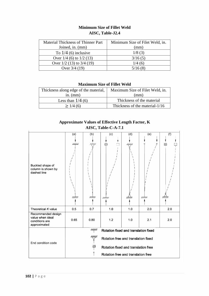
102 | P a g e
Minimum Size of Fillet Weld
AISC, Table-J2.4
Material Thickness of Thinner Part
Joined, in. (mm)
Minimum Size of Filet Weld, in.
(mm)
To 1/4 (6) inclusive 1/8 (3)
Over 1/4 (6) to 1/2 (13) 3/16 (5)
Over 1/2 (13) to 3/4 (19) 1/4 (6)
Over 3/4 (19) 5/16 (8)
Maximum Size of Fillet Weld
Thickness along edge of the material,
in. (mm)
Maximum Size of Filet Weld, in.
(mm)
Less than 1/4 (6) Thickness of the material
≥ 1/4 (6) Thickness of the material-1/16
Approximate Values of Effective Length Factor, K
AISC, Table-C-A-7.1

103 | P a g e
Available Shear Stress in Plate Girders
AISC table, 3-16 to 3-17
104 | P a g e

105 | P a g e

106 | P a g e