CBE 150A – Transport Spring Semester 2014 Shell and Tube Heat Exchangers.
36
CBE 150A – Transport Spring Semester 2014 Shell and Tube Heat Exchangers
-
Upload
gregory-ferguson -
Category
Documents
-
view
218 -
download
0
Transcript of CBE 150A – Transport Spring Semester 2014 Shell and Tube Heat Exchangers.

CBE 150A – Transport Spring Semester 2014
Shell and Tube Heat Exchangers
CBE 150A – Transport Spring Semester 2014
Goals:
By the end of today’s lecture, you should be able to: describe the common shell-and-tube HE designs draw temperature profiles for parallel and counter-current flow in a shell-and-tube HE calculate the true mean temperature difference for a shell-and-tube HE (use FG chart) make heat transfer calculations for shell-and-tube HEs describe how the inside and outside heat transfer coefficients are determined for shell-and-tube HEs use the Donohue equation to estimate ho in a multiple pass heat
exchanger make heat transfer calculations for multiple pass shell-and-tube heat exchangers

CBE 150A – Transport Spring Semester 2014
Outline:
I. Review
II. Shell-and-tube equipment
III. Rate equation and TTM
IV. Ten Minute Problem - FG for multiple pass
HE
V. Heat transfer coefficients
VI. Example Problem - Handout
CBE 150A – Transport Spring Semester 2014
I. Review
Last time, we reviewed heat transfer in double pipe (concentric pipe) heat exchangers.
We considered cases of parallel and countercurrent flow of the hot and cold fluids in the concentric pipe design.
The basic equations required in the design of a heat exchanger are the enthalpy balances on both fluid streams and a rate equation that defines the heat transfer rate.

CBE 150A – Transport Spring Semester 2014
Enthalpy balances for fluids without phase change:
(hot stream) and (cold stream) If a phase change occurs (the hot stream is condensed), then the heat of condensation (vaporization) must be accounted for:
In most applications, the heat gained by the cold stream can be assumed to equal the heat lost by the hot stream (i.e., qh = qc).
hphhh TCmq cpccc TCmq
.. condhcond mq

CBE 150A – Transport Spring Semester 2014
The rate of heat transfer for a concentric pipe heat exchanger with parallel or countercurrent flow can be written as:
or
where TTM is the true mean temperature difference.
For concentric pipe heat exchangers, the true mean temperature difference is equal to the log mean temperature difference (TLM).
TMii TULDq )( TMTUAq ii

CBE 150A – Transport Spring Semester 2014
R e c a l l , t h e o v e r a l l h e a t t r a n s f e r c o e f f i c i e n t i sw r i t t e n a s :
1
U o A o
1
U i A i
1
h i A i
x
kA LM
1
h o A o
CBE 150A – Transport Spring Semester 2014
II. Shell-and-Tube Equipment
Concentric Pipe vs. Shell & Tube Heat Exchangers:
The simple double pipe heat exchanger is inadequate for flow rates that cannot readily be handled in a few tubes. Double pipe heat exchangers are not used for required heat exchange areas in excess of 100-150 ft2. Several double pipe heat exchangers can be used in parallel, but it proves more economical to have a single shell serve for multiple tubes.
CBE 150A – Transport Spring Semester 2014
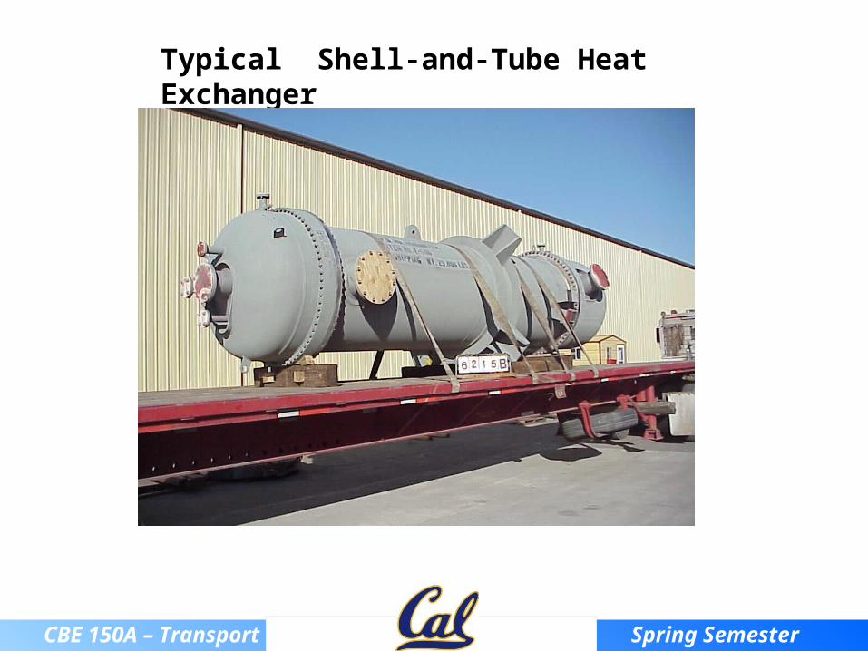
Typical Shell-and-Tube Heat Exchanger
CBE 150A – Transport Spring Semester 2014
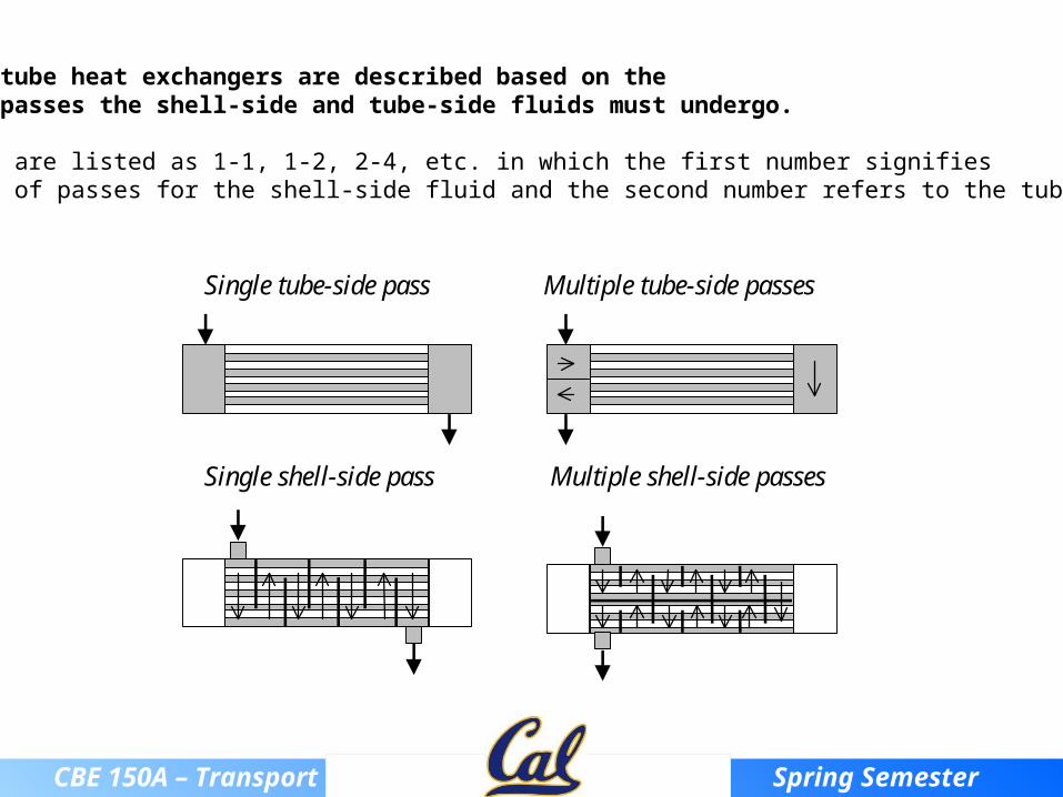
Shell-and-tube heat exchangers are described based on the number of passes the shell-side and tube-side fluids must undergo.
Exchangers are listed as 1-1, 1-2, 2-4, etc. in which the first number signifies the number of passes for the shell-side fluid and the second number refers to the tube-side fluid.
Single tube-side pass Multiple tube-side passes
Single shell-side pass Multiple shell-side passes
CBE 150A – Transport Spring Semester 2014
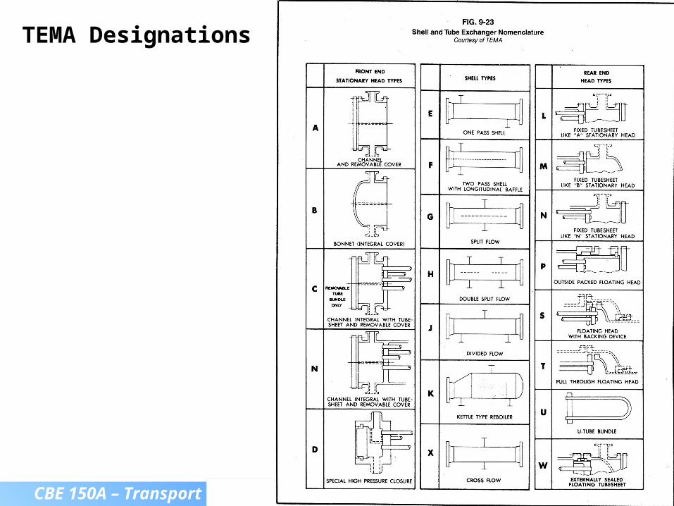
TEMA Designations
CBE 150A – Transport Spring Semester 2014
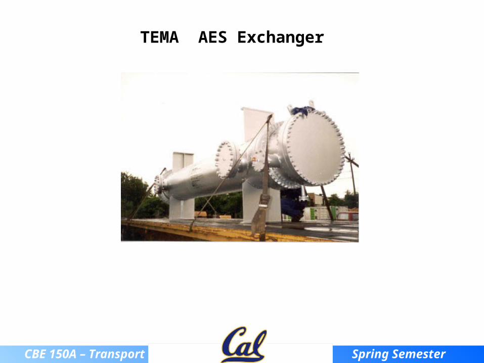
TEMA AES Exchanger
CBE 150A – Transport Spring Semester 2014
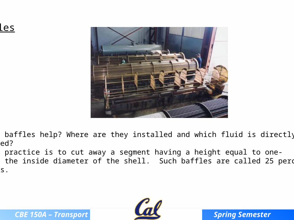
Baffles
How do baffles help? Where are they installed and which fluid is directly affected?Common practice is to cut away a segment having a height equal to one-fourth the inside diameter of the shell. Such baffles are called 25 percent baffles.

CBE 150A – Transport Spring Semester 2014
Baffle Arrangement

CBE 150A – Transport Spring Semester 2014
The RODbaffle heat exchanger design (Phillips Petroleum Co.)
CBE 150A – Transport Spring Semester 2014
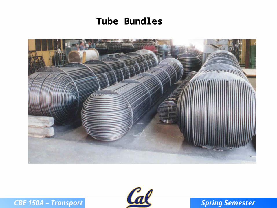
Tube Bundles

CBE 150A – Transport Spring Semester 2014
Tube sizesTube sizes
Tubes Standard tube lengths are 8, 12, 16 and 20 ft.
Tubes are drawn to definite wall thickness in terms of BWG and true outside diameter (OD), and they are available in all common metals.
CBE 150A – Transport Spring Semester 2014
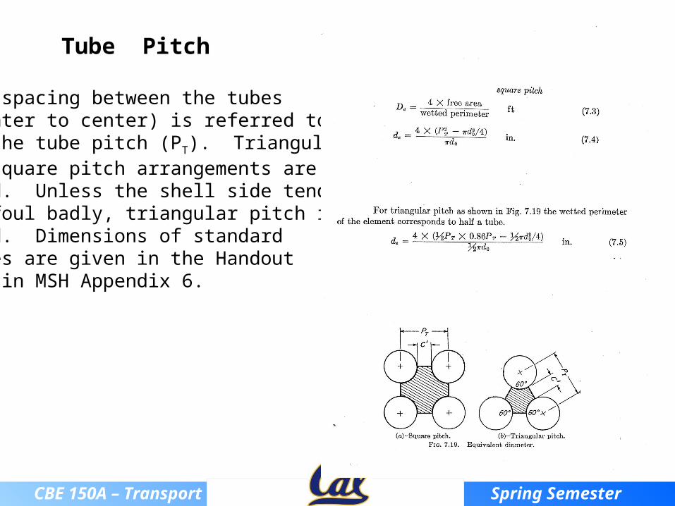
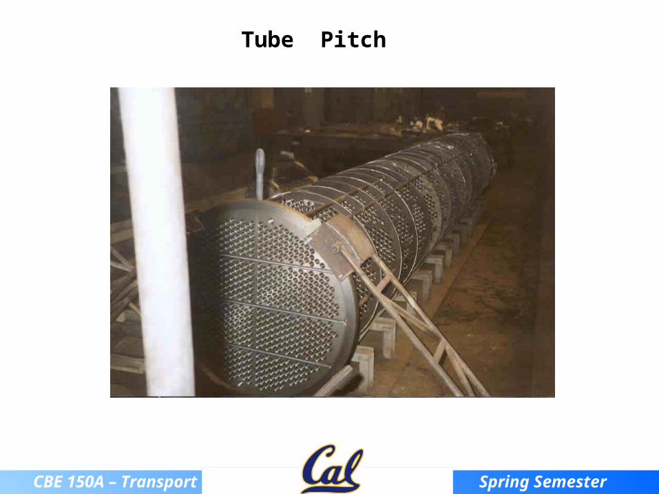
The spacing between the tubes (center to center) is referred to as the tube pitch (PT). Triangular or square pitch arrangements are used. Unless the shell side tends to foul badly, triangular pitch is Used. Dimensions of standard tubes are given in the Handout and in MSH Appendix 6.
Tube Pitch
CBE 150A – Transport Spring Semester 2014
Tube Pitch

CBE 150A – Transport Spring Semester 2014
III. Rate equation and TTM
The rate equation for a shell-and-tube heat exchanger is the same as for a concentric pipe exchanger:
However, Ui and TTM are evaluated somewhat differently for shell-and-tube exchangers. We will first discuss how to evaluate TTM and then a little later in the notes we will discuss how to evaluate Ui for shell-and-tube exchangers.In a shell-and-tube exchanger, the flow can be single or multipass. As a result, the temperature profiles for the two fluids in a shell-and-tube heat exchanger are more complex, as shown below.
TMTUAq ii
TMTUAq ii

CBE 150A – Transport Spring Semester 2014
Computation of TTM:
For the concentric pipe heat exchanger, we showed the following (parallel and countercurrent flow):
TTM =
When a fluid flows perpendicular to a heated or cooled tube bank, and if both of the fluid temperatures are varying, then the temperature conditions do not correspond to either parallel or countercurrent. Instead, this is called crossflow.
Tlm

CBE 150A – Transport Spring Semester 2014
F o r c ro s s f lo w a n d m u l t ip a s s h e a t e x c h a n g e d e s ig n s , w e m u s t in t ro d u c e a c o r re c t io n f o r th e lo g m e a n te m p e ra tu r e d i f f e re n c e ( L M T D ) :
T T M =
Z T ha T hb
T cb T ca
H Tcb Tca
T ha T ca
FG * TLM

CBE 150A – Transport Spring Semester 2014
The factor Z is the ratio of the fall in temperature of the shell side fluid to the rise in temperature of the tube side fluid.
The factor H is the heating effectiveness, or the ratio of the actual temperature rise of the tube side fluid to the maximum possible temperature rise obtainable (if the shell inlet end approach were zero, based on countercurrent flow).
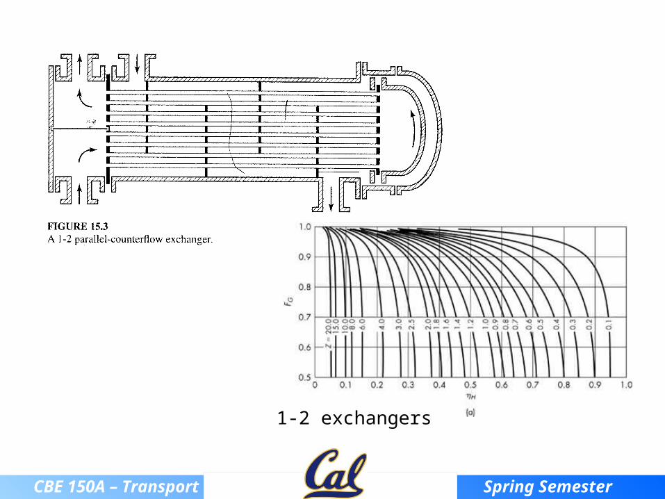
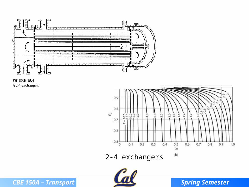
From the given values of H and Z, the factor FG can be read from the following figures:
CBE 150A – Transport Spring Semester 2014
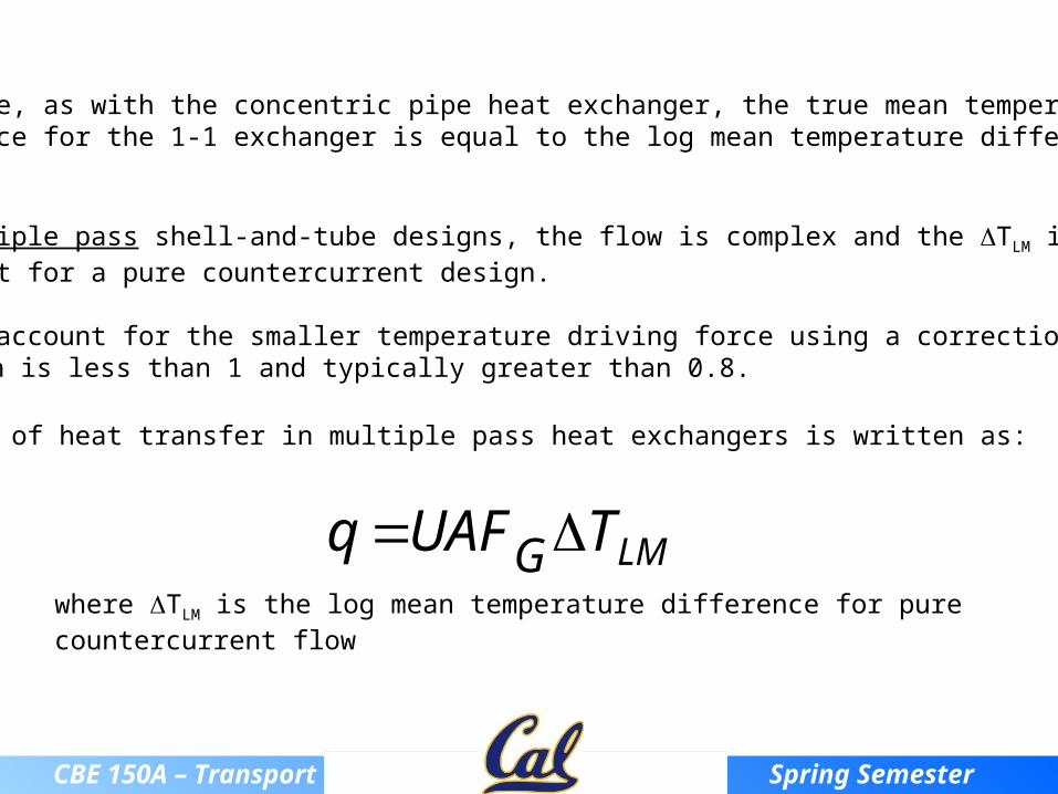
Therefore, as with the concentric pipe heat exchanger, the true mean temperature difference for the 1-1 exchanger is equal to the log mean temperature difference (TLM).
For multiple pass shell-and-tube designs, the flow is complex and the TLM is less than that for a pure countercurrent design.
We must account for the smaller temperature driving force using a correction factor, FG, which is less than 1 and typically greater than 0.8.
The rate of heat transfer in multiple pass heat exchangers is written as:
LMTUAFq Gwhere TLM is the log mean temperature difference for pure countercurrent flow
CBE 150A – Transport Spring Semester 2014
1-2 exchangers
CBE 150A – Transport Spring Semester 2014
2-4 exchangers

CBE 150A – Transport Spring Semester 2014
IV. Ten Minute Problem -- FG for multiple pass HE
For a 2-4 heat exchanger with the cold fluid inside the tubes and the following temperatures:
Tca = 85°F Tha = 200°FTcb = 125°F Thb = 100°F
(a) What is the true mean temperature difference?(answer TTM = 31.7°F)
(b) What exchanger area is required to cool 50,000 lbm/hr of product (shell-side fluid) if the overall heat transfer coefficient is 100 Btu/hr-ft2-°F and Cp for the product is 0.45 Btu/lbm-°F?(answer A = 710 ft2)

CBE 150A – Transport Spring Semester 2014
V. Heat transfer coefficients
In a shell-and-tube exchanger, the shell-side and tube-side heat transfer coefficients are of comparable importance and both must be large if a satisfactory overall coefficient is to be attained.

CBE 150A – Transport Spring Semester 2014
T u b e - s i d e c o e f f i c i e n t :
T h e h e a t t r a n s f e r c o e f f i c i e n t f o r i n s i d e t h e t u b e s ( h i ) c a n b e c a l c u l a t e d u s i n g t h e S i e d e r - T a t e e q u a t i o n f o r t u r b u l e n t f l o w i n a c o n s t a n t d i a m e t e r p i p e :
hD
k
0 . 023
DG
0 . 8C p
k
0 . 333 w
0 . 14

CBE 150A – Transport Spring Semester 2014
Shell-side coefficient: The heat transfer coefficient for the shell side cannot be calculated using the correlations discussed so far since the direction of flow is partly perpendicular to the tubes and partly parallel. An approximate equation for predicting shell-side coefficients is the Donohue equation:

CBE 150A – Transport Spring Semester 2014
The Donohue equation is based on the weighted average of the mass velocity of the shell-side fluid flowing parallel to the tubes (Gb) and the mass velocity of the shell-side fluid flowing across the tubes (Gc):
hoDo
k
0.2
DoGe
0.6 Cp
k
0.33w
0.14
where
Ge = (GbGc)
1/2
bb SmG / , Sb fbDs
2
4 Nb
Do2
4
fb = fraction of the shell cross-section occupied by the baffle window. Nb = number of tubes in baffle window m is the mass flow rate of the shell-side fluid Do = outside diameter of tubes Ds = inside diameter of the shell P = baffle spacing p = tube pitch
cc SmG / Sc PDs 1 Do
p
Gb
GbGc

CBE 150A – Transport Spring Semester 2014
Sb fbDs
2
4 Nb
Do2
4
fb = fraction of the shell cross-section occupied by the baffle window. For a 25 percent baffle cut, fb = 0.1955
Flow Area Through Baffle “Window” - Sb
Ds
Baffle Cut
Baffle Window Area
Tube Diameter Do

CBE 150A – Transport Spring Semester 2014
Flow Area Across Tube Bundle - Sc
Sc PDs 1 Do
p
P
Ds
Do
p

CBE 150A – Transport Spring Semester 2014
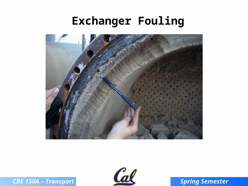
Exchanger Fouling
Electron microscope image showing fibers, dust, and other deposited material on aresidential air conditioner coil and a fouled water line in a water heater.
CBE 150A – Transport Spring Semester 2014
Exchanger Fouling
CBE 150A – Transport Spring Semester 2014
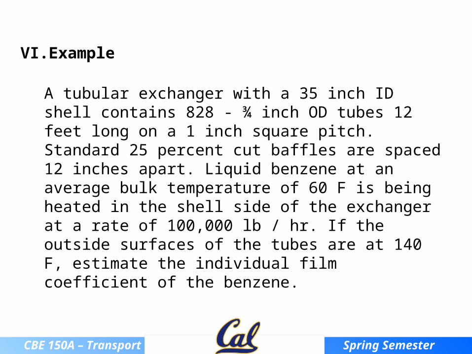
VI. Example
A tubular exchanger with a 35 inch ID shell contains 828 - ¾ inch OD tubes 12 feet long on a 1 inch square pitch. Standard 25 percent cut baffles are spaced 12 inches apart. Liquid benzene at an average bulk temperature of 60 F is being heated in the shell side of the exchanger at a rate of 100,000 lb / hr. If the outside surfaces of the tubes are at 140 F, estimate the individual film coefficient of the benzene.