Cassini Spacecraft Mission Study
17
CASSINI SPACECRAFT MISSION STUDY ANDREW B. HALES A CASSINI SPACECRAFT MISSION STUDY ANDREW B. HALES Table of Contents Table of Contents ....................................................................................................................................... 1 1. Introduction............................................................................................................................................ 2 2. Origin of the Cassini Mission ................................................................................................................ 2 3. Selection Process .................................................................................................................................... 2 4. Goal and Objectives ............................................................................................................................... 5 4.1. Observation of Titan......................................................................................................................5 4.2. Observation of the Magnetosphere ...............................................................................................6 4.3. Observation of Icy Satellites .........................................................................................................6 4.4. Observation of Saturn’s Ring System............................................................................................6 4.5. Observation of Saturn ...................................................................................................................6 5. The Cassini and Huygens Spacecraft ..................................................................................................... 7 5.1. Cassini Spacecraft Layout..............................................................................................................7 5.2. Cassini Electrical Power................................................................................................................7 5.3. Maintenance and Control...............................................................................................................9 5.3. Communications and Data Recording...........................................................................................9 5.4. Huygens Spacecraft Layout...........................................................................................................9 6. Launch.................................................................................................................................................. 10 6.1 Launch Vehicle.............................................................................................................................10 6.2 Launch Sequence..........................................................................................................................10 7. Planetary Swingbys ............................................................................................................................. 12 8. Arrival at Saturn................................................................................................................................... 13 8.1. Saturn Orbit Insertion...................................................................................................................13 8.2. Huygens Probe Insertion .............................................................................................................14 9. Orbital Tour of the Saturnian System .................................................................................................. 16 9.1 Decommissioning Cassini ............................................................................................................16 References ................................................................................................................................. ............... 17
-
Upload
andrew-ben-hales -
Category
Documents
-
view
224 -
download
0
Transcript of Cassini Spacecraft Mission Study
8/6/2019 Cassini Spacecraft Mission Study
http://slidepdf.com/reader/full/cassini-spacecraft-mission-study 1/17
1
CASSINI SPACECRAFT MISSION STUDY ANDREW B. HALES
A
CASSINI SPACECRAFT MISSION STUDYANDREW B. HALES
Table of Contents
Table of Contents ................................................................................................................................... ....1
1. Introduction ............................................................................................................................................2
2. Origin of the Cassini Mission ........................................................................................................... .....2
3. Selection Process ....................................................................................................................................2
4. Goal and Objectives ........................................................................................................................... ....5
4.1. Observation of Titan......................................................................................................................5
4.2. Observation of the Magnetosphere ...............................................................................................6
4.3. Observation of Icy Satellites .........................................................................................................6
4.4. Observation of Saturn’s Ring System............................................................................................6
4.5. Observation of Saturn ...................................................................................................................65. The Cassini and Huygens Spacecraft .....................................................................................................7
5.1. Cassini Spacecraft Layout..............................................................................................................7
5.2. Cassini Electrical Power................................................................................................................7
5.3. Maintenance and Control...............................................................................................................9
5.3. Communications and Data Recording...........................................................................................9
5.4. Huygens Spacecraft Layout...........................................................................................................9
6. Launch ..................................................................................................................................................10
6.1 Launch Vehicle.............................................................................................................................10
6.2 Launch Sequence..........................................................................................................................10
7. Planetary Swingbys .............................................................................................................................12
8. Arrival at Saturn ...................................................................................................................................13
8.1. Saturn Orbit Insertion...................................................................................................................13
8.2. Huygens Probe Insertion .............................................................................................................14
9. Orbital Tour of the Saturnian System .............................................................................................. ....16
9.1 Decommissioning Cassini ............................................................................................................16
References ............................................................................................................................................... .17
8/6/2019 Cassini Spacecraft Mission Study
http://slidepdf.com/reader/full/cassini-spacecraft-mission-study 2/17
1
CASSINI SPACECRAFT MISSION STUDY ANDREW B. HALES
A
1. Introduction
The planet Saturn is the second largest in the solar system and has been noted by virtually every
civilisation in ancient history. Saturn has the most extensive system of rings compared to any other
planet in the solar system. The prominent system of rings mostly consists of icy particles with smallamounts of rock debris and dust. The planet is so massive it has sixty-one moons as well as hundreds of
moonlets circling the planet within the rings. Some of the moons orbiting Saturn can be considered “icy
satellites” due to their high percentage composition of water. The largest moon orbiting Saturn is
Titan, which is the second largest in the galaxy and is significantly larger than the planet Mercury.
Titan is the only moon in the galaxy to posses a dense veiling atmosphere.
The Cassini Mission will perform close-up studies of Saturn, its rings, moons and magnetic
environment. The moon Titan will be of special interest because of the atmospheric and surface
characteristics it possibly shared with early planet Earth. The Spacecraft will make in situ and remote
observations under geometric and temporal conditions not available from Earth.
2. Origin of the Cassini Mission
The mission and Orbiter spacecraft is named after the French/Italian astronomer Giovanni DomenicoCassini. He discovered several of the Saturnian satellites and ring features between years 1671-1685.
The atmospheric Huygens Probe that will explore Titan is named after Dutch Astronomer Christiaan
Huygens, who discovered the moon in 1655.
The Cassini Program is a cooperative international partnership between the National Aeronautics and
Space Administration (NASA), The European Space Agency (ESA) and The Italian Space Agency
(ASI). The mission is managed by NASA’s Jet Propulsion Laboratory in Pasadena, California. This
was also where the Orbiter was developed and manufactured. Development of the Huygens Titan Probe
was carried out by the European Space Technology and Research Centre (ESTEC). Huygens batteries
and two of pieces of scientific equipment came from the U.S. ASI is contributing the orbiter’s dished
high-gain antenna and significant pieces of three science instruments. NASA’s Deep Space Network is
used for communications with Cassini during the mission. Stations are located in California, Spain and
Australia. Data from the Huygens probe will be sent to a communications complex in Darmstadt,
Germany.
3. Selection Process
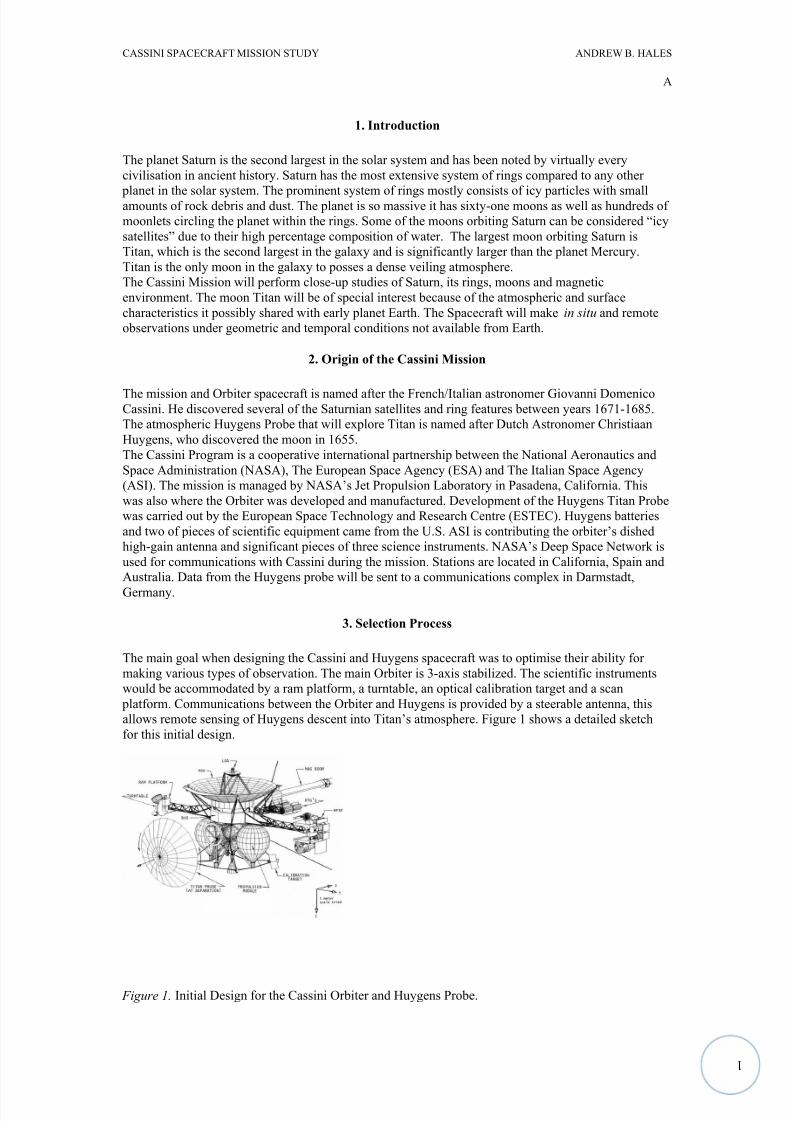
The main goal when designing the Cassini and Huygens spacecraft was to optimise their ability for
making various types of observation. The main Orbiter is 3-axis stabilized. The scientific instruments
would be accommodated by a ram platform, a turntable, an optical calibration target and a scan
platform. Communications between the Orbiter and Huygens is provided by a steerable antenna, this
allows remote sensing of Huygens descent into Titan’s atmosphere. Figure 1 shows a detailed sketch
for this initial design.
Figure 1. Initial Design for the Cassini Orbiter and Huygens Probe.
8/6/2019 Cassini Spacecraft Mission Study
http://slidepdf.com/reader/full/cassini-spacecraft-mission-study 3/17
1
CASSINI SPACECRAFT MISSION STUDY ANDREW B. HALES
A
The designs of the initial Orbiter and Probe were scrapped in the early development phase because of
control of development and operational costs. As a result engineering complexity was traded for a
greater operational complexity. At the same time some of the scientific objectives were given up such
as asteroid fly-by, Jupiter fly-by and cruising science.
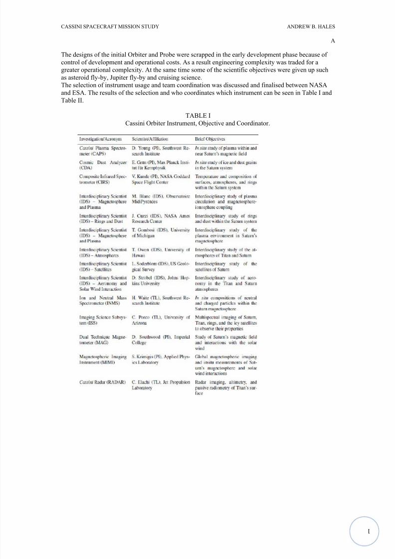
The selection of instrument usage and team coordination was discussed and finalised between NASA
and ESA. The results of the selection and who coordinates which instrument can be seen in Table I and
Table II.
TABLE I
Cassini Orbiter Instrument, Objective and Coordinator.
8/6/2019 Cassini Spacecraft Mission Study
http://slidepdf.com/reader/full/cassini-spacecraft-mission-study 4/17
1
CASSINI SPACECRAFT MISSION STUDY ANDREW B. HALES
A
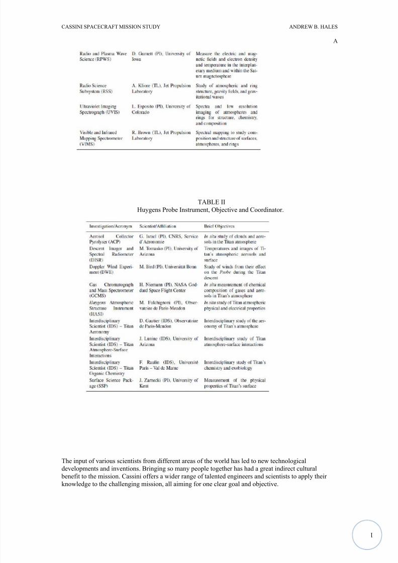
TABLE II
Huygens Probe Instrument, Objective and Coordinator.
The input of various scientists from different areas of the world has led to new technological
developments and inventions. Bringing so many people together has had a great indirect cultural
benefit to the mission. Cassini offers a wider range of talented engineers and scientists to apply their
knowledge to the challenging mission, all aiming for one clear goal and objective.
8/6/2019 Cassini Spacecraft Mission Study
http://slidepdf.com/reader/full/cassini-spacecraft-mission-study 5/17
1
CASSINI SPACECRAFT MISSION STUDY ANDREW B. HALES
A
4. Goal and Objectives
The primary goal of Cassini/Huygens is “to conduct an in-depth exploration of the Saturnian
System” (NASA, 1989).
Although many other spacecraft have explored the Saturnian system before Cassini, a greater understanding of the system, its moons, its ring and its atmosphere was needed. Voyager 1 and 2, and
Pioneer II each flew through the Saturnian system and gave very brief but eye opening observations. A
clearer more in depth study of Titan in particular was needed, as it was revealed as a new and unique
object.
Cassini/Huygens is designed to determine the present state of Saturn, the rings, Titan, icy satellites and
the magnetosphere. The specialised equipment and mission duration allows the orbiter and probe to
make the same observations at different periods of time, allowing comparison of results. This allows
interactions between different systems to by observed and understood. These interactions are very
complicated; thanks to the complexity of the instrument sets, the interactions are addressed. Many of
the spacecraft instruments need to operate simultaneously; this has a huge impact on electrical power
usage. This requirement as well as the need for a diverse collection of equipment able to operate in the
Saturnian system is the reason why the Cassini/Huygens spacecraft is one of the largest to data.
Certain objectives for the different parts of the Saturnian system was established by NASA and ESA,some of the required observations were prioritised. The objectives from the following lists are taken
from the NASA/ESA mission brief, no significance should be taken from the order of their appearance.
4.1. Observation of Titan
Titan is the major focus of the mission. It will be studied by both the Huygens Probe and the Cassini
Orbiter. The scientific objectives are to:
• Determine abundances of atmospheric constituents (including any noble gases; establish isotoperatios for abundant elements; constrain scenarios of formation and evolution of Titan and its
atmosphere.
• Observe vertical and horizontal distributions of trace gases; search for more complex organicmolecules; investigate energy sources for atmospheric chemistry; model the photochemistry of the
stratosphere; study formation and composition of aerosols;
• Measure winds and global temperatures; investigate cloud physics, general circulation and seasonal effects in Titan’s atmosphere; search for lightning discharges;
• Determine the physical state, topography and the composition of the surface; infer the internal
structure of the satellite;
• Investigate the upper atmosphere, its ionization, and its role as a source of neutral and ionized material for the magnetosphere of Saturn. While the formal set of scientific objectives is the same for
both Probe and Orbiter, several additional constraints apply with respect to the synergistic gathering
of data. ‘In the design of the Huygens measurements and Orbiter observations it is highly desirablethat the value of the whole set of data be maximized’. To strive for this synergistic effect, there are
some specific objectives that have been identified;
• ‘Each time the Orbiter will fly by Titan, it will perform a set of atmosphere and surface remote
sensing observations which will include re-observations of the atmosphere and surface along the flight path of the Probe.
• In this respect the Probe data will provide a reference set of data which will be used to ‘calibrate’ the
Orbiter observations. The Probe data will be used, together with the Orbiter data, for studying spatial and seasonal variations of the atmosphere composition and dynamics.’
(ESA, 1989)
8/6/2019 Cassini Spacecraft Mission Study
http://slidepdf.com/reader/full/cassini-spacecraft-mission-study 6/17
1
CASSINI SPACECRAFT MISSION STUDY ANDREW B. HALES
A
4.2. Observation of the Magnetosphere
Specific Cassini objectives for magnetospheric and plasma science is to:
• Determine the configuration of the nearly axially symmetric magnetic field and its relation to the
modulation of Saturn Kilometric Radiation (SKR).
• Determine current systems, composition, sources, and sinks of magnetosphere charged particles.
• Investigate wave-particle interactions and dynamics of the dayside magnetosphere and themagnetotail of Saturn and their interactions with the solar wind, the satellites and the rings.
• Study the effect of Titan’s interaction with the solar wind and magnetospheric plasma.
• Investigate interactions of Titan’s atmosphere and exosphere with the surrounding Plasma.
(ESA, 1989)
4.3. Observation of Icy Satellites
Specific Cassini objectives for icy satellite science are to:
• Determine the general characteristics and geological histories of the satellites.
• Define the mechanisms of crustal and surface modifications, both external and internal.
• Investigate the compositions and distributions of surface materials, particularly dark, organic rich
materials and low melting point condensed volatiles.
• Constrain models of the satellites’ bulk compositions and internal structures.
• Investigate interactions with the magnetosphere and ring systems and possible gas injections into the
magnetosphere. (NASA, 1989)
4.4. Observation of Saturn’s Ring System
Specific Cassini objectives for the ring science are to:
• Study configuration of the rings and dynamical processes (gravitational, viscous, erosional, and electromagnetic) responsible for ring structure.
• Map composition and size distribution of ring material.
• Investigate interrelation of rings and satellites, including imbedded satellites.
• Determine dust and meteoroid distribution in the vicinity of the rings.
• Study interactions between the rings and Saturn’s magnetosphere, ionosphere, and atmosphere.
(NASA, 1989)
4.5. Observation of Saturn
Cassini objectives for Saturn are to:
• Determine temperature field, cloud properties, and composition of the atmosphere of Saturn.• Measure the global wind field, including wave and eddy components; observe synoptic cloud features
and processes.
• Infer the internal structure and rotation of the deep atmosphere.
8/6/2019 Cassini Spacecraft Mission Study
http://slidepdf.com/reader/full/cassini-spacecraft-mission-study 7/17
1
CASSINI SPACECRAFT MISSION STUDY ANDREW B. HALES
A
• Study the diurnal variations and magnetic control of the ionosphere of Saturn.
• Provide observational constraints (gas composition, isotope ratios, heat flux, etc.) on scenarios for the formation and the evolution of Saturn.
• Investigate the sources and the morphology of Saturn lightning (Saturn Electrostatic Discharges(SED), lightning whistlers). (NASA/ESA, 1989)
5. The Cassini and Huygens Spacecraft
5.1. Cassini Spacecraft Layout
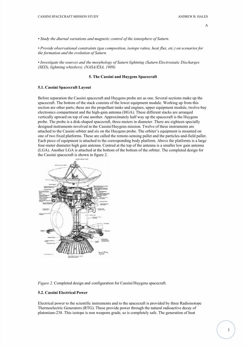
Before separation the Cassini spacecraft and Huygens probe are as one. Several sections make up the
spacecraft. The bottom of the stack consists of the lower equipment module. Working up from this
section are other parts; these are the propellant tanks and engines, upper equipment module, twelve-bay
electronics compartment and the high-gain antenna (HGA). These different stacks are arranged
vertically upward on top of one another. Approximately half way up the spacecraft is the Huygens
probe. The probe is a disk-shaped spacecraft, three-meters in diameter. There are eighteen speciallydesigned instruments involved in the Cassini/Huygens mission. Twelve of these instruments are
attached to the Cassini orbiter and six on the Huygens probe. The orbiter’s equipment is mounted on
one of two fixed platforms. These are called the remote-sensing pallet and the particles-and-field pallet.
Each piece of equipment is attached to the corresponding body platform. Above the platforms is a large
four-meter diameter high gain antenna. Centred at the top of the antenna is a smaller low gain antenna
(LGA). Another LGA is attached at the bottom of the bottom of the orbiter. The completed design for
the Cassini spacecraft is shown in figure 2.
Figure 2. Completed design and configuration for Cassini/Huygens spacecraft.
5.2. Cassini Electrical Power
Electrical power to the scientific instruments and to the spacecraft is provided by three RadioisotopeThermoelectric Generators (RTG). These provide power through the natural radioactive decay of
plutonium-238. This isotope is non weapons grade, so is completely safe. The generation of heat
8/6/2019 Cassini Spacecraft Mission Study
http://slidepdf.com/reader/full/cassini-spacecraft-mission-study 8/17
1
CASSINI SPACECRAFT MISSION STUDY ANDREW B. HALES
A
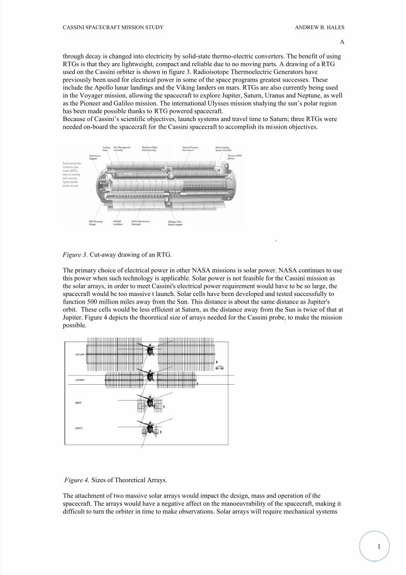
through decay is changed into electricity by solid-state thermo-electric converters. The benefit of using
RTGs is that they are lightweight, compact and reliable due to no moving parts. A drawing of a RTG
used on the Cassini orbiter is shown in figure 3. Radioisotope Thermoelectric Generators have
previously been used for electrical power in some of the space programs greatest successes. These
include the Apollo lunar landings and the Viking landers on mars. RTGs are also currently being used
in the Voyager mission, allowing the spacecraft to explore Jupiter, Saturn, Uranus and Neptune, as well
as the Pioneer and Galileo mission. The international Ulysses mission studying the sun’s polar region
has been made possible thanks to RTG powered spacecraft.
Because of Cassini’s scientific objectives, launch systems and travel time to Saturn; three RTGs were
needed on-board the spacecraft for the Cassini spacecraft to accomplish its mission objectives.
.
Figure 3. Cut-away drawing of an RTG.
The primary choice of electrical power in other NASA missions is solar power. NASA continues to use
this power when such technology is applicable. Solar power is not feasible for the Cassini mission as
the solar arrays, in order to meet Cassini's electrical power requirement would have to be so large, the
spacecraft would be too massive t launch. Solar cells have been developed and tested successfully to
function 500 million miles away from the Sun. This distance is about the same distance as Jupiter'sorbit. These cells would be less efficient at Saturn, as the distance away from the Sun is twice of that at
Jupiter. Figure 4 depicts the theoretical size of arrays needed for the Cassini probe, to make the mission
possible.
Figure 4. Sizes of Theoretical Arrays.
The attachment of two massive solar arrays would impact the design, mass and operation of the
spacecraft. The arrays would have a negative affect on the manoeuvrability of the spacecraft, making itdifficult to turn the orbiter in time to make observations. Solar arrays will require mechanical systems
8/6/2019 Cassini Spacecraft Mission Study
http://slidepdf.com/reader/full/cassini-spacecraft-mission-study 9/17
1
CASSINI SPACECRAFT MISSION STUDY ANDREW B. HALES
A
to extend themselves after launch. Mechanical failure due to the complexity of moving parts would
render the mission a failure. Large arrays greatly increase the overall weight of the spacecraft, requiring
greater thrust in order to launch orbiter and probe into orbit. RTGs are the only feasible power system
for the Cassini/Huygens mission.
5.3. Maintenance and Control
Some of scientific instruments and parts of the spacecraft are sensitive to high temperatures or low
temperatures and need to be maintained. The Cassini and Huygens protect equipment through several
means. Insulation and blankets are wrapped around or cover equipment, reflective coatings are painted
on some areas of the orbiter and probe to reflect sunlight, shade is provided by other parts of the
spacecraft, heat produced by the normal operation of some devices help keep areas of the spacecraft
warm and small radio-isotope heaters are installed to keep some instruments warm.
The Cassini spacecraft is stabilized in three axes. Thrusters with a force of 0.5N can change the attitude
of the aircraft. Attitude changes will need to be carried out frequently, so that the instruments on the
body-fixed platforms can be pointed at their desired target. The whole spacecraft must be turned and
rotated in order to point the instruments.
5.3. Communications and Data Recording
Two way communications between Cassini and Earth is carried out through the Deep Space Network
(DSN) via an X-band radio link. These communications use the orbiters high gain antenna, or one of
the low gain antenna. The high gain antenna is also used for communications between itself and
Huygens, as well as carrying out radio and radar experiments.
The primary data storage device used on the orbiter is called the Solid State Recorder (SSR). The
spacecraft is equipped with two of these, each with a capacity of 1.8 Gigabits. The SSR will store
spacecraft telemetry and attitude articulation and control (AACS), command and data subsystem (CDS)
and instrument memory-loads in separate partitions.
5.4. Huygens Spacecraft Layout
The Huygens probe system consists of the probe itself as well as the Probe Support Equipment (PSE)
which is attached to the orbiter. The PSE includes a spin eject device, which releases a strong spring
loaded mechanism that propels the probe away from the orbiter and imparts a spin about its axis. The
rotation of the probe is approximately 5rpm and separates at a relative velocity of 0.4m/s. The probe
ways 305kg and the PSE weighs 35kg. The Huygens probe is a conical shaped capsule which has a
high drag coefficient. It consists of the descent module that has an enclosed thermal protection shell.
This protects the probe from heat generation from atmospheric entry. Once the probe's parachute is
deployed, the protective shell is released allowing Huygens to safely land on the surface of Titan.
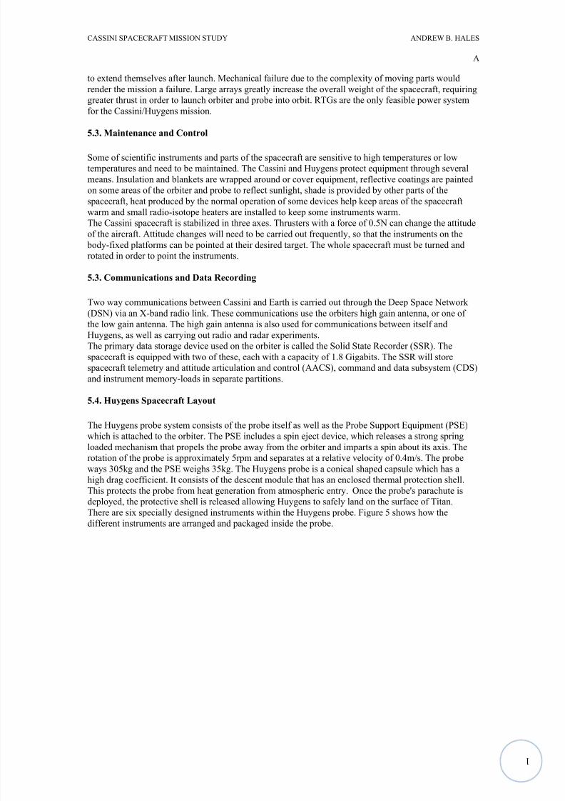
There are six specially designed instruments within the Huygens probe. Figure 5 shows how the
different instruments are arranged and packaged inside the probe.
8/6/2019 Cassini Spacecraft Mission Study
http://slidepdf.com/reader/full/cassini-spacecraft-mission-study 10/17
1
CASSINI SPACECRAFT MISSION STUDY ANDREW B. HALES
A
Figure 5. Layout of Huygens' Instruments.
6. Launch
6.1 Launch Vehicle
The launch vehicle was a Titan IVB with two Solid Rocket Motor Upgrades (SMRU) attached at the
lower stage. On the top of the propulsion stack was a Centaur rocket, above this on the uppermost stage
is the payload, or the Cassini/Huygens spacecraft. The Titan vehicle has two main stages. The SMR|Us
are anchored to the first lower stage. SMRUs are basically strap on rockets to provide extra propulsion
required for launch info orbit. They burn solid fuel, whereas the Titan uses liquid-fuel. The second
stage is the Centaur rocket, which is a versatile, high energy and cryogenic liquid fuelled. This rocket
system had two multiple start engines. The performance of the combined Titan IVB/SRMU-Centaur
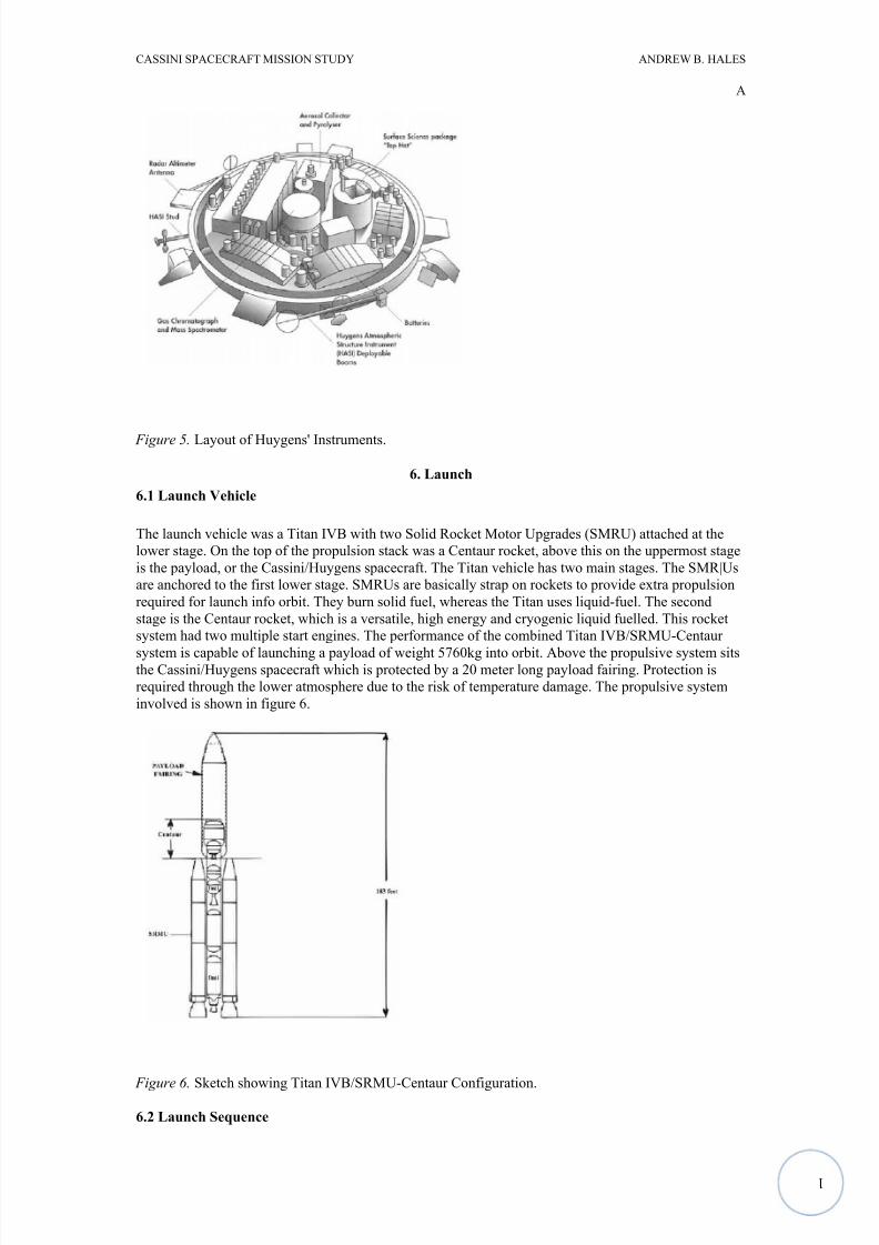
system is capable of launching a payload of weight 5760kg into orbit. Above the propulsive system sitsthe Cassini/Huygens spacecraft which is protected by a 20 meter long payload fairing. Protection is
required through the lower atmosphere due to the risk of temperature damage. The propulsive system
involved is shown in figure 6.
Figure 6. Sketch showing Titan IVB/SRMU-Centaur Configuration.
6.2 Launch Sequence
8/6/2019 Cassini Spacecraft Mission Study
http://slidepdf.com/reader/full/cassini-spacecraft-mission-study 11/17
1
CASSINI SPACECRAFT MISSION STUDY ANDREW B. HALES
A
Lift off took place at night from Cape Canaveral. The launch sequence began with the ignition of the
two SMRUs. The whole stack was lifted off the pad with the thrust produced. 10 seconds after the
ignition of SMRU the stack continued to accelerate and tilt and rotate. Rotation occurred until the
required azimuth (The horizontal angular distance from a reference direction, usually the northern point
of the horizon, to the point where a vertical circle through a celestial body intersects the horizon) was
reached. Two minutes into the launch, the first stage of Titan was ignited. The altitude was 192000 feet
approximately. A few second after the ignition of Titan, the two SMRUs were jettisoned because they
were spent. The whole system reached an altitude of 360000 feet in a further one and a half minutes
and the payload fairing was released. Five and a half minutes into the flight and 549000 feet was
reached and the first stage of Titan separated and the second stage fired. At launch plus 9 minutes,
stage two had fully burnt out and was dropped away. The Centaur then fired and boosted the remaining
rocket and spacecraft into a parking orbit and switched off its engines. Sixteen minutes after the turn
off the rockets were re-ignited for a second time. It burnt for a further 8 minutes before the Centaur was
separated from the Cassini spacecraft. Cassini/Huygens was now in an interplanetary trajectory. The
whole launch was executed perfectly; the spacecraft was now heading for swingbys of Venus, Venus
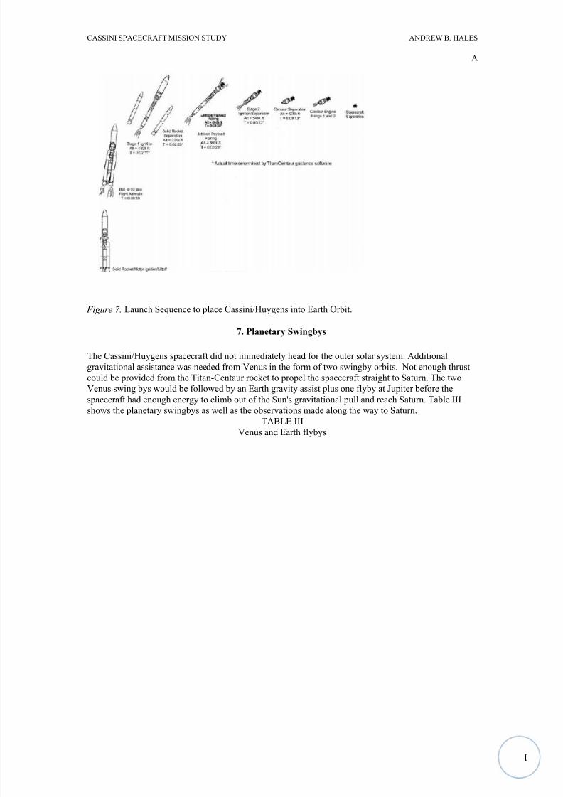
again, Earth and Jupiter, before reaching and orbiting Saturn. Figure 7 shows the launch sequence
events.
8/6/2019 Cassini Spacecraft Mission Study
http://slidepdf.com/reader/full/cassini-spacecraft-mission-study 12/17
1
CASSINI SPACECRAFT MISSION STUDY ANDREW B. HALES
A
Figure 7. Launch Sequence to place Cassini/Huygens into Earth Orbit.
7. Planetary Swingbys
The Cassini/Huygens spacecraft did not immediately head for the outer solar system. Additional
gravitational assistance was needed from Venus in the form of two swingby orbits. Not enough thrust
could be provided from the Titan-Centaur rocket to propel the spacecraft straight to Saturn. The two
Venus swing bys would be followed by an Earth gravity assist plus one flyby at Jupiter before the
spacecraft had enough energy to climb out of the Sun's gravitational pull and reach Saturn. Table III
shows the planetary swingbys as well as the observations made along the way to Saturn.
TABLE IIIVenus and Earth flybys
8/6/2019 Cassini Spacecraft Mission Study
http://slidepdf.com/reader/full/cassini-spacecraft-mission-study 13/17
1
CASSINI SPACECRAFT MISSION STUDY ANDREW B. HALES
A
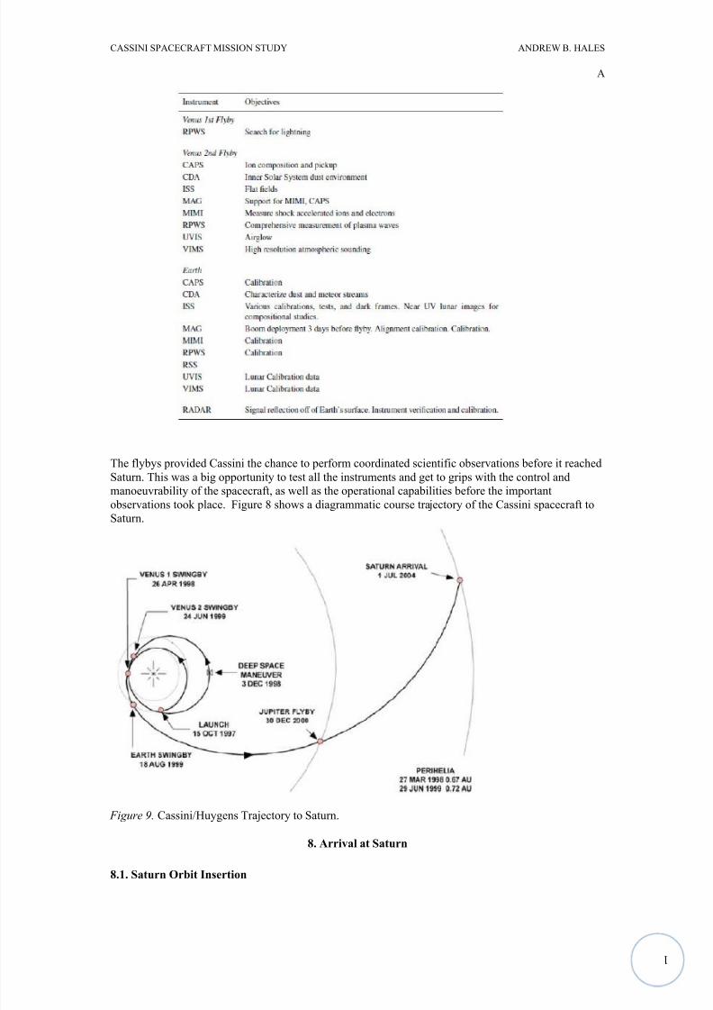
The flybys provided Cassini the chance to perform coordinated scientific observations before it reached
Saturn. This was a big opportunity to test all the instruments and get to grips with the control and
manoeuvrability of the spacecraft, as well as the operational capabilities before the important
observations took place. Figure 8 shows a diagrammatic course trajectory of the Cassini spacecraft to
Saturn.
Figure 9. Cassini/Huygens Trajectory to Saturn.
8. Arrival at Saturn
8.1. Saturn Orbit Insertion
8/6/2019 Cassini Spacecraft Mission Study
http://slidepdf.com/reader/full/cassini-spacecraft-mission-study 14/17
1
CASSINI SPACECRAFT MISSION STUDY ANDREW B. HALES
A
Before arriving at Saturn, Cassini began making synoptic observations 2 months before arrival in order
to refine the knowledge of Titan and to characterise the rings and the planet. This was done as early as
possible as soon as a few tenths of pixels came into view of Cassini's imaging instruments.
The Cassini Orbiter is inserted into Saturn orbit on the 1 July 2004. The Saturn Orbit Insertion (SOI)
burn begins at the spacecrafts closest approach to Saturn. The manoeuvres just before SOI are planned
to insure the correct trajectory for the orbit insertion manoeuvre. Any manoeuvres after the SOI are
only to course correct any errors during the entry burn. The Cassini/Huygens spacecraft is the forth to
pass through Saturn's rings, and is inserted to pass through a region known to be free of particles. The
spacecraft is designed to withstand small debris collision expected through the empty region. The SOI
manoeuvre is a 97 minute engine burn with a total increase in velocity (ΔV) of 633m/s. when the
required velocity change has been made an accelerometer will end the burn. The spacecraft is then
steered at a constant angular velocity rate. The engine gimble actuator keeps the main engine pointed
near the velocity vector; this keeps the thrust efficiency at a maximum. After the burn has ended and
sloshing in the fuel tanks has subsided, the spacecraft is rolled 60-70° to allow the ORS instruments to
be switched on to view Saturn's inner rings.
8.2. Huygens Probe Insertion
On the third orbit of Saturn, the Huygens probe is set on course by the Probe Targeting Manoeuvre tointersect Titan. The Cassini Orbiter turns to aim the probe at Titan. On Christmas day 2004, the spin
eject mechanism releases Huygens and imparts a 5rpm axial spin. Twenty-two days after release,
Huygens reaches Titan. During landing of the probe, the Orbiter fires an engine and executes the
orbiter deflection manoeuvre. This sets the course 60000 km away from Titan and at the right time to
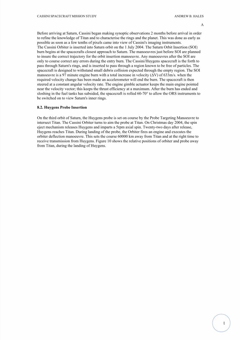
receive transmission from Huygens. Figure 10 shows the relative positions of orbiter and probe away
from Titan, during the landing of Huygens.
8/6/2019 Cassini Spacecraft Mission Study
http://slidepdf.com/reader/full/cassini-spacecraft-mission-study 15/17
1
CASSINI SPACECRAFT MISSION STUDY ANDREW B. HALES
A
Figure 10. position of Orbiter and Probe During Huygens Mission.
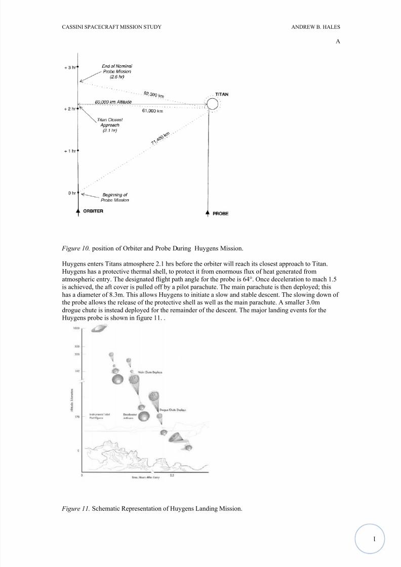
Huygens enters Titans atmosphere 2.1 hrs before the orbiter will reach its closest approach to Titan.
Huygens has a protective thermal shell, to protect it from enormous flux of heat generated from
atmospheric entry. The designated flight path angle for the probe is 64°. Once deceleration to mach 1.5
is achieved, the aft cover is pulled off by a pilot parachute. The main parachute is then deployed; this
has a diameter of 8.3m. This allows Huygens to initiate a slow and stable descent. The slowing down of the probe allows the release of the protective shell as well as the main parachute. A smaller 3.0m
drogue chute is instead deployed for the remainder of the descent. The major landing events for the
Huygens probe is shown in figure 11. .
Figure 11. Schematic Representation of Huygens Landing Mission.
8/6/2019 Cassini Spacecraft Mission Study
http://slidepdf.com/reader/full/cassini-spacecraft-mission-study 16/17
1
CASSINI SPACECRAFT MISSION STUDY ANDREW B. HALES
A
9. Orbital Tour of the Saturnian System
After Huygens is delivered to the surface of Titan, Cassini is put back into orbits that take it to the icy
satellites. From there Cassini explores the volume of the magnetosphere and to high latitudes to
observer the rings. Further flybys of Titan, provide opportunities to study and observe the moon as well
as gravitational assists to other possible ventures. The tour of Cassini/Huygens consists of 76 Saturn-centred orbits. They are navigated by using propulsive manoeuvres and 45 Titan gravity assists. Titan
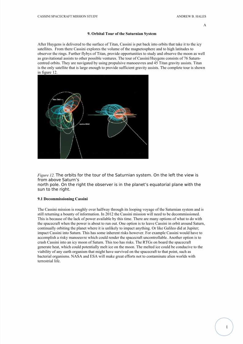
is the only satellite that is large enough to provide sufficient gravity assists. The complete tour is shown
in figure 12.
Figure 12. The orbits for the tour of the Saturnian system. On the left the view is
from above Saturn’snorth pole. On the right the observer is in the planet’s equatorial plane with thesun to the right.
9.1 Decommissioning Cassini
The Cassini mission is roughly over halfway through its looping voyage of the Saturnian system and is
still returning a bounty of information. In 2012 the Cassini mission will need to be decommissioned.
This is because of the lack of power available by this time. There are many options of what to do with
the spacecraft when the power is about to run out. One option is to leave Cassini in orbit around Saturn,
continually orbiting the planet where it is unlikely to impact anything. Or like Galileo did at Jupiter;
impact Cassini into Saturn. This has some inherent risks however. For example Cassini would have to
accomplish a risky manoeuvre which could render the spacecraft uncontrollable. Another option is to
crash Cassini into an icy moon of Saturn. This too has risks. The RTGs on board the spacecraftgenerate heat, which could potentially melt ice on the moon. The melted ice could be conducive to the
viability of any earth organism that might have survived on the spacecraft to that point, such as
bacterial organisms. NASA and ESA will make great efforts not to contaminate alien worlds with
terrestrial life.
8/6/2019 Cassini Spacecraft Mission Study
http://slidepdf.com/reader/full/cassini-spacecraft-mission-study 17/17
CASSINI SPACECRAFT MISSION STUDY ANDREW B. HALES
A
References
[1] MATSON, Dennis, et al (2002). The Cassini/Huygens Mission to the Saturnian System. [online],
last accessed 21.5.10.
[2] LEBRATON, J.P, et al (2002). The Huygens Probe: Science, Payload and Mission Overview.
[online], last accessed 21.5.10.
[3] JAFFE, Leanard (1997). Cassini/Huygens Science Instruments, Spacecraft and Mission. [online],
last accessed 21.5.10.
[4] Anon, (1995). Cassini's Earthly Benefits. [online], last accessed 21.5.10.
[5] Anon, (1996). Why the Cassini Mission Cannot Use Solar Arrays. [online], last accessed 21.5.10.
[6] POWELL, D (2006). Death of a Spacecraft: The Unknown Fate of Cassini. [online] last accessed
21.5.10 at < http://www.space.com/businesstechnology/061108_cassini_fate.html >