CASE STUDY OF PROCESS INNOVATION FOR MANUFACTURING …
6
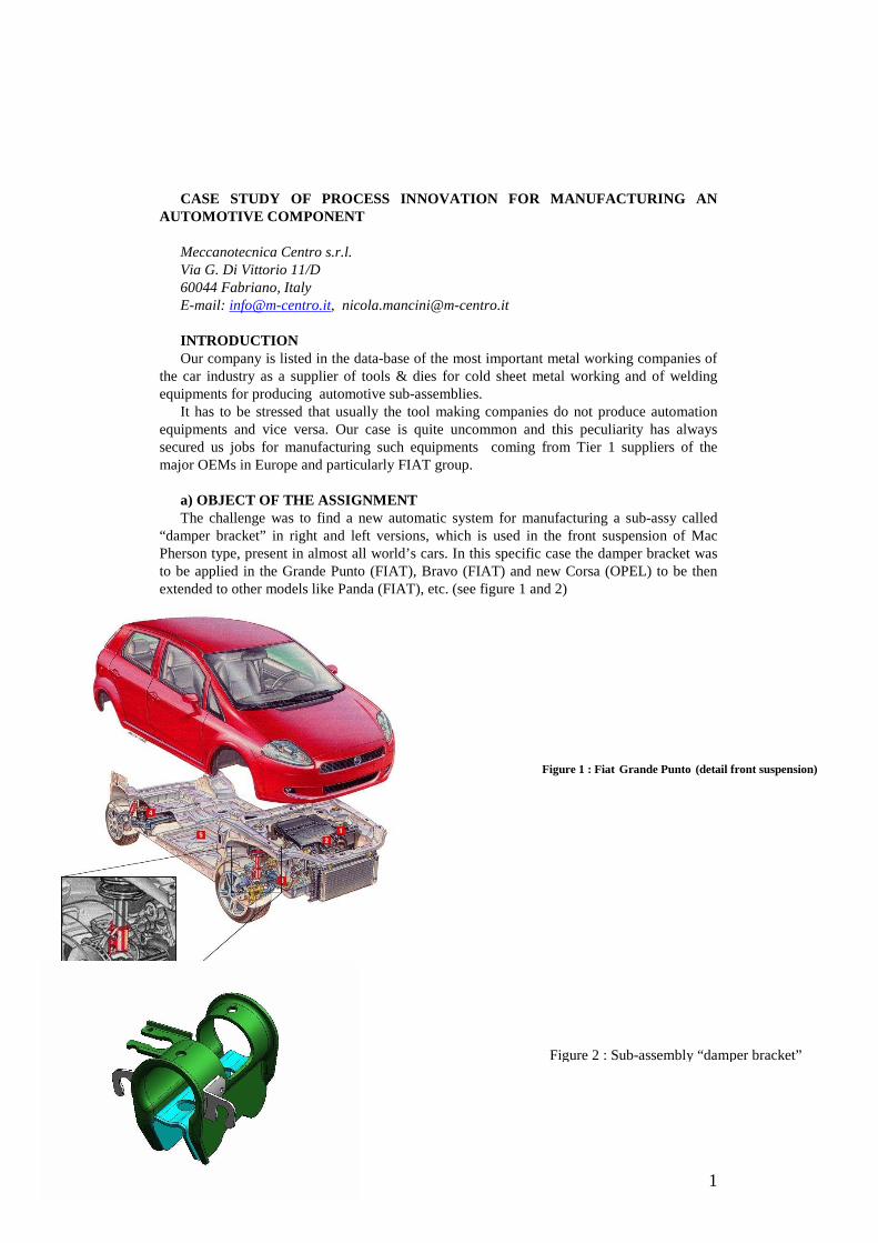
1 CASE STUDY OF PROCESS INNOVATION FOR MANUFACTURING AN AUTOMOTIVE COMPONENT Meccanotecnica Centro s.r.l. Via G. Di Vittorio 11/D 60044 Fabriano, Italy E-mail: [email protected] , [email protected] INTRODUCTION Our company is listed in the data-base of the most important metal working companies of the car industry as a supplier of tools & dies for cold sheet metal working and of welding equipments for producing automotive sub-assemblies. It has to be stressed that usually the tool making companies do not produce automation equipments and vice versa. Our case is quite uncommon and this peculiarity has always secured us jobs for manufacturing such equipments coming from Tier 1 suppliers of the major OEMs in Europe and particularly FIAT group. a) OBJECT OF THE ASSIGNMENT The challenge was to find a new automatic system for manufacturing a sub-assy called “damper bracket” in right and left versions, which is used in the front suspension of Mac Pherson type, present in almost all world’s cars. In this specific case the damper bracket was to be applied in the Grande Punto (FIAT), Bravo (FIAT) and new Corsa (OPEL) to be then extended to other models like Panda (FIAT), etc. (see figure 1 and 2) Figure 2 : Sub-assembly “damper bracket” Figure 1 : Fiat Grande Punto (detail front suspension)
Transcript of CASE STUDY OF PROCESS INNOVATION FOR MANUFACTURING …
1
CASE STUDY OF PROCESS INNOVATION FOR MANUFACTURING AN
AUTOMOTIVE COMPONENT Meccanotecnica Centro s.r.l. Via G. Di Vittorio 11/D 60044 Fabriano, Italy E-mail: [email protected], [email protected] INTRODUCTION Our company is listed in the data-base of the most important metal working companies of
the car industry as a supplier of tools & dies for cold sheet metal working and of welding equipments for producing automotive sub-assemblies.
It has to be stressed that usually the tool making companies do not produce automation equipments and vice versa. Our case is quite uncommon and this peculiarity has always secured us jobs for manufacturing such equipments coming from Tier 1 suppliers of the major OEMs in Europe and particularly FIAT group.
a) OBJECT OF THE ASSIGNMENT The challenge was to find a new automatic system for manufacturing a sub-assy called
“damper bracket” in right and left versions, which is used in the front suspension of Mac Pherson type, present in almost all world’s cars. In this specific case the damper bracket was to be applied in the Grande Punto (FIAT), Bravo (FIAT) and new Corsa (OPEL) to be then extended to other models like Panda (FIAT), etc. (see figure 1 and 2)
Figure 2 : Sub-assembly “damper bracket”
Figure 1 : Fiat Grande Punto (detail front suspension)

2
The job assignment also included the supply of the dies for producing the lose components to be assembled. The decision of putting all equipments under the responsibility of one single supplier by the client proved to be very fortunate because it allowed a considerable simplification in the production of the components to be assembled.
It should be noted that the boost for innovation originated from the huge volume of production (more than 800.000 pieces per year) so that automation would have brought a big saving in terms of labour cost.
b) DESCRIPTION OF WELDED COMPONENT AND PRODUCTION PROCESS The component - exploded diagram in figure 3 - was planned for 2 series:
� series 20 – diameter of sleeve Ø 44,70 ± 0,1 � series 40 – diameter of sleeve Ø 46,15 ± 0,1.
Figure 3 : Explosion of damper bracket The sleeve hosting the Mac Phersons’s suspension stem is the central element of the sub-
assy and is manufactured with a die, one die stamps the 20-series and another one stamps the 40-series. The ABS brackets are manufactured with two different dies (one for the left bracket and one for the right bracket), each die was conceived to stamp both series. The concept was very appreciated by the client; in fact it has allowed a big saving in terms of investment (2 dies instead of 4) and an easier handling because of the reduction of item codes.
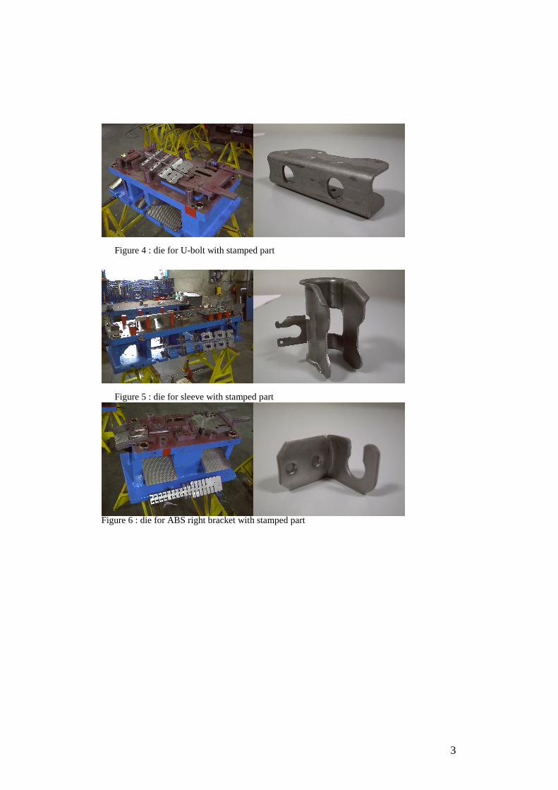
A similar die concept was applied to the U-Bolt part. It was unified for both series 20 and 40. The stamping dies were at the end 5 instead of 8, as originally indicated by the client and the codes to be handled 8 instead of 11. The figures 4,5 and 6 show some excerpts of the dies.
SLEEVE
BRACKET ABS right
U – BOLT
BRACKET ABS left
3
Figure 4 : die for U-bolt with stamped part Figure 5 : die for sleeve with stamped part
Figure 6 : die for ABS right bracket with stamped part

4
c) STUDY AND DESCRIPTION OF THE WELDING CELL It was possible to conceive the simplification of the manufacturing process first of all
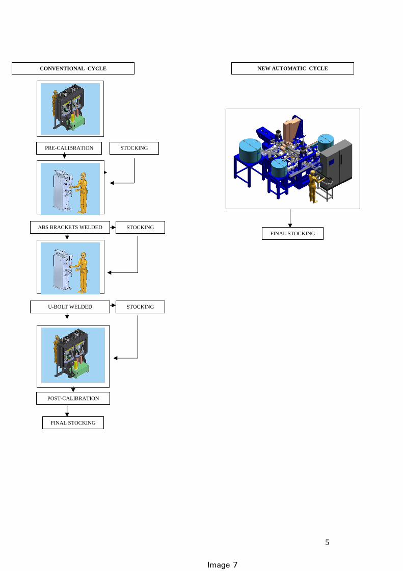
because we carried out a global study, due to the fact that we had to manufacture not only the dies but also the welding machine for assembling the single components of the damper brackets. During the study we immediately felt the necessity of reducing the number of parts to be welded so as to simplify the machine itself and therefore reduce the investment costs to an acceptable value. Again, this has been possible only because Meccanotecnica Centro not only manufactures dies but also industrial welding equipment – driven by the need of a single global method we could integrate both services. For understanding the range of the process innovation look at image 7 comparing the traditional manufacturing cycle with the automatic cycle that we worked out. The conventional cycle is made of 4 steps involving the manual picking of the lose parts by a first operator and the download of the half-finished part in a stocking area, from where a second operator manually picks the half-finished part to feed the welding machine. This type of cycle causes alienation and therefore extends the cycle time. Besides it inevitably increases the rest time for reducing the operator’s stress. This leads to a cost increase and potentially to a quality decrease because in time repetitiveness of simple actions reduces the attention level.
In our cycle the innovation consists in the automatic feeding of the ABS brackets (left and
right) and of the u-bolt by means of vibrating cups (see image 7). Only the sleeve is fed manually because its dimensions and weight would cause excessive cost if made automatically. One person monitoring the general functioning was needed anyway, so the task of feeding the sleeve was assigned to him. The output is one sub-assembly every 15 seconds; a cycle time significantly smaller than the conventional process
The working phases of the machine are:
� Calibration of the sleeve � Welding of one or both ABS brackets (right and left) depending on the model � Welding of the U-bolt � Calibration of the grade of opening of the U-bolt and of the direction of the ABS brackets � Calibration of the welded sub-assy (first of all there is the calibration of the diameter of the
sleeve which must stay under ± 0,1 tolerance) � The machine is equipped with a control device of the right quantity of required electricity
required for welding � Download of the welded piece is automatic, directly in the container. The parts that are not
conform to the set criteria are automatically discharged at bottom line. In fact the welding control detects the good part (that is welded with the right current parameters) from the not good one, that is lead out on the side of the machine.
� Statistical control on the production, that is number of produced parts and number of defect parts
5
Image 7
CONVENTIONAL CYCLE
PRE-CALIBRATION
ABS BRACKETS WELDED
U-BOLT WELDED
POST-CALIBRATION
STOCKING
STOCKING
STOCKING
FINAL STOCKING
NEW AUTOMATIC CYCLE
FINAL STOCKING

6