Case Study for GV-Hot Swap NVR System V5pd.geovision.tw/.../GV-Hot_Swap_NVR_V5_Case_Study.pdf · 1...
10
1 Case Study for GV-Hot Swap NVR System V5: Multi-Story Building with Retail Stores, Offices and Parking Lot Article ID: GV5-13-11-14-t Release Date: 11/14/2013 Table of Contents 1. Case Brief ........................................................................................................... 2 2. Suggested Installation ....................................................................................... 3 3. Purchase List for the Suggested Installation .................................................. 4 3.1 GeoVision Products................................................................................................... 4 3.2 Non-GeoVision Products ........................................................................................... 5 4. Recommendations and Limitations for GV-Hot Swap NVR System V5 ......... 7 4.1 Suggested Hard Disk Arrangement ........................................................................... 7 4.2 Recommended Hard Disk Brand .............................................................................. 8 4.3 Suggested Network Arrangement ............................................................................. 9 5. Ethernet Cable Requirements ........................................................................... 9 6. Appendix........................................................................................................... 10
Transcript of Case Study for GV-Hot Swap NVR System V5pd.geovision.tw/.../GV-Hot_Swap_NVR_V5_Case_Study.pdf · 1...

1
Case Study for GV-Hot Swap NVR System V5:
Multi-Story Building with Retail Stores, Offices and
Parking Lot
Article ID: GV5-13-11-14-t
Release Date: 11/14/2013
Table of Contents
1. Case Brief ........................................................................................................... 2
2. Suggested Installation....................................................................................... 3
3. Purchase List for the Suggested Installation .................................................. 4
3.1 GeoVision Products...................................................................................................4
3.2 Non-GeoVision Products...........................................................................................5
4. Recommendations and Limitations for GV-Hot Swap NVR System V5......... 7
4.1 Suggested Hard Disk Arrangement...........................................................................7
4.2 Recommended Hard Disk Brand ..............................................................................8
4.3 Suggested Network Arrangement .............................................................................9
5. Ethernet Cable Requirements ........................................................................... 9
6. Appendix........................................................................................................... 10

2
1. Case Brief
The client needed a surveillance solution to ensure the safety of a multi-story building. Floors
3 to 4 are parking lots, the second floor is retail area, and the first floor includes retail area and
restaurants and a security guard room. Located in the basement is the security control room
and office area for employees.
2 GV-SD220-S and 4 GV-BL2410 were installed on the 4th floors to monitor the activities in
the parking lots. The PTZ capability of GV-SD220-S makes them ideal for tracking movements
in the parking lot. The parking lot on the 3rd floor is set up the same way with 2 GV-SD220-S
and 4 GV-BL2410.
A retail store occupies the entire 2nd floor and part of the 1st floor, and the retail areas are
covered by 32 GV-BX2400. An additional 9 GV-BX2400 were mounted to record the
transactions at the 9 cash registers on the 1st floor, and each cash register has a POS system
installed with GeoVision’s POS Text Sender. Also on the ground floor are 10 GV-BL2410 to
cover the loading zone at the back door, elevator entrances, and parking lot entrances. At the
main entrance, a GV-FE4301 fisheye camera was mounted on the ceiling to monitor all
angles. In addition, 3 GV-3D People Counters and Asus Xtion Pro Live were set up to count
the number of customers entering and exiting.
In the basement, a security control room was set up to house 2 20-bay GV-Hot Swap NVR
System V5, which receive and record all 64 IP cameras installed in the building, and can send
videos to the GV-Center V2. The GV-Center V2 is located in a security guard room on the 1st
floor, and during closed hours, the security guard can receive live videos and alert messages
upon motion detection on the GV-Center V2. During business hours, the staff in the basement
office can monitor all 64 IP channels on the GV-Hot Swap NVR System V5. If the 2 GV-Hot
Swap NVR System V5 fail to record for whatever reason, the GV-Failover Server in B1 will
take over and make sure the videos are recorded properly.
Alarm buttons were mounted in the restroom stalls on floors 1 to 4, and each floor uses an
8-port GV-I/O Box to relay the alert to the GV-Hot Swap NVR System V5. When the alarm
button is pushed in the event of an emergency, the B1 and 1F security staff will be notified and
the E-Map on the GV-Hot Swap NVR System V5 allows staff to quickly locate the alarm button
pushed.

3
2. Suggested Installation

4
3. Purchase List for the Suggested Installation
3.1 GeoVision Products
Floor Products Quantity Note
GV-SD220-S 2
GV-BL2410 4
GV-I/O Box 8 ports 1
4F Parking
GV-PoE0801 Switch 1 8 PoE ports, 10/100BaseTX, PSE
plus 2-port Gigabit Uplink
GV-SD220-S 2
GV-BL2410 4
GV-I/O Box 8 ports 1
3F Parking
GV-PoE0801 Switch 1 8 PoE ports, 10/100BaseTX, PSE
plus 2-port Gigabit Uplink
GV-BX2400 20
GV-I/O Box 8 ports 1
2F Retail
GV-PoE2401 Switch 1 24 PoE ports, 2 Gigabit TP/SFP
Combo Uplink ports
GV-BX2400 21
GV-FE4301 1
GV-BL2410 10
GV-PoE2401 Switch 2 24 PoE ports, 2 Gigabit TP/SFP
Combo Uplink ports
GV-I/O Box 8 ports 1
GV-3D People Counter 3
1F Retail
GV-POS Text Sender S/W 9 Install on the 9 POS Systems
1F Security GV-Center V2 S/W 1 Install on desktop computer
GV-Hot Swap NVR System V5-
4U, 20-Bay
2
GV-POS Text Sender Dongle 1 12 ports (Install on 1 GV-Hot Swap
NVR System V5)
B1 Office &
Control
Room
GV-Failover Server (SW +
Dongle)
1 Install on desktop computer

5
3.2 Non-GeoVision Products
Floor Products Quantity Details
Network Cable
8 1. Cat 5e x 4 (GV-BL2410 to GV-PoE0801)
2. Cat 5e x 2 (GV-SD220-S to GV-PoE0801)
3. Cat 5e x 1 (GV-I/O Box to GV-PoE0801)
4. Cat 6 x 1 (GV-PoE0801 to 8 ports Gigabit
Switch)
4F Parking
Alarm Button
(Normally Open)
5 - 8
To connect with GV-I/O Box
Network Cable
8 1. Cat 5e x 4 (GV-BL2410 to GV-PoE0801)
2. Cat 5e x 2 (GV-SD220-S to GV-PoE0801)
3. Cat 5e x 1 (GV-I/O Box to GV-PoE0801)
4. Cat 6 x 1 (GV-PoE0801 to 8 ports Gigabit
Switch)
3F Parking
Alarm Button
(Normally Open)
5 - 8 To connect with GV-I/O Box
Network Cable 22 1. Cat 5e x 20 (GV-BX2400 to GV-PoE2401)
2. Cat 5e x 1 (GV-I/O Box to GV-PoE2401)
3. Cat 6 x 1 (GV-PoE2401 to 8 ports Gigabit
Switch)
2F Retail
Alarm Button
(Normally Open)
5 - 8 To connect with GV-I/O Box
Asus Xtion Pro Live 3 To connect with GV-3D People Counter 1F Retail
Network Cable 47 1. Cat 5e x 21 (GV-BX2400 to GV-PoE2401)
2. Cat 5e x 1 (GV-FE4301 to GV-PoE02401)
3. Cat 5e x 10 (GV-BL2410 to GV-PoE2401)
4. Cat 5e x 1 (GV-I/O Box to GV-PoE2401)
5. Cat 5e x 9 (POS System to GV-PoE2401)
6. Cat 5e x 3 (GV-3D People Counter to
GV-PoE2401)
7. Cat 6 x 2 (GV-PoE2401 to 8 ports Gigabit
Switch)
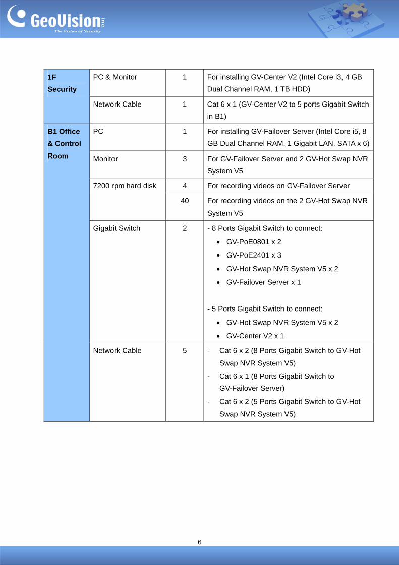
6
PC & Monitor 1 For installing GV-Center V2 (Intel Core i3, 4 GB
Dual Channel RAM, 1 TB HDD)
1F
Security
Network Cable 1 Cat 6 x 1 (GV-Center V2 to 5 ports Gigabit Switch
in B1)
PC 1 For installing GV-Failover Server (Intel Core i5, 8
GB Dual Channel RAM, 1 Gigabit LAN, SATA x 6)
Monitor 3 For GV-Failover Server and 2 GV-Hot Swap NVR
System V5
4 For recording videos on GV-Failover Server 7200 rpm hard disk
40 For recording videos on the 2 GV-Hot Swap NVR
System V5
Gigabit Switch 2 - 8 Ports Gigabit Switch to connect:
GV-PoE0801 x 2
GV-PoE2401 x 3
GV-Hot Swap NVR System V5 x 2
GV-Failover Server x 1
- 5 Ports Gigabit Switch to connect:
GV-Hot Swap NVR System V5 x 2
GV-Center V2 x 1
B1 Office
& Control
Room
Network Cable 5 - Cat 6 x 2 (8 Ports Gigabit Switch to GV-Hot
Swap NVR System V5)
- Cat 6 x 1 (8 Ports Gigabit Switch to
GV-Failover Server)
- Cat 6 x 2 (5 Ports Gigabit Switch to GV-Hot
Swap NVR System V5)

7
4. Recommendations and Limitations for GV-Hot Swap NVR System V5
4.1 Suggested Hard Disk Arrangement
The table below shows how to arrange 40 2TB hard disks for recording in two 20-bay
GV-Hot Swap NVR System V5 and the number of days you can record under
Round-the-Clock (RTC) Mode and Motion Detection Mode. Each GV-Hot Swap NVR System
V5 will record 32 channels. You can divide the 32 channels into 4 storage groups and assign 5
hard disks to each storage group. The GV-IP Cameras are set to VBR (Variable Bit Rate)
mode.
Recording Capacity Storage
Group
Camera Hard Disk
RTC Motion
Group 1
4F: GV-SD220-S x 2
4F: GV-BL2410 x 4
3F: GV-SD220-S x 2
HDD 1 ~ 5
Group 2 3F: GV-BL2410 x 4
2F: GV-BX2400 x 4 HDD 6 ~ 10
Group 3 2F: GV-BX2400 x 8 HDD 11 ~ 15
GV-Hot
Swap NVR
System V5
#1
Group 4 2F: GV-BX2400 x 8 HDD 16 ~ 20
Group 1 1F: GV-BX2400 x 8 HDD 1 ~ 5
Group 2 1F: GV-BX2400 x 8 HDD 6 ~ 10
Group 3
1F: GV-BX2400 x 5
1F: GV-FE4301 x 1
1F: GV-BL2410 x 2
HDD 11 ~ 15
GV-Hot
Swap NVR
System V5
#2
Group 4 1F: GV-BL2410 x 8 HDD 16 ~ 20
At least 19
days of
data
At least 38
days of
data
Note:
1. For Motion Detection mode, It is assumed that there are 500 motion events per day that each lasts 1 minute.
2. The data is based on calculation from the GV-IP Camera Bandwidth and Recording Size
Calculator: http://www.geovision.com.tw/english/Bandwidth.asp
3. The number of hard disks assigned for a storage group may depend on the actual
environments. Under Motion Detection Mode, You may assign more hard disks to the group
that would have more motion events.

8
4.2 Recommended Hard Disk Brand
To maintain system stability and to keep your recordings safe when using GeoVision software,
we advise you to use any of the recommended and/or the tested hard disk drives listed below.
Brand Series
Barracuda (XT Series, ES.2 Series, 7200 Series)
SV35 Series
Seagate
Constellation ES Series
Hitachi Hitachi Series
Caviar Black
Caviar Blue
Western Digital
RE Series
To find the tested hard disk models, see:
http://pd.geovision.tw/technotice/Others/Recommended_HDD.pdf

9
4.3 Suggested Network Arrangement
GV-Hot Swap NVR System V5 has two built-in Gigabit Ethernet ports. In the recommended
installation illustrated above, each of the two GV-Hot Swap NVR System V5 receives video
from 32 GV-IP Cameras installed in the building, and then transmits the 32 IP channels to
GV-Center V2. In this case, set one Gigabit Ethernet for the incoming 32 channels and one
Gigabit Ethernet port for the outgoing 32 channels.
Two Gigabit switches are installed to avoid network bottleneck. You will need to use one
Gigabit switch for the incoming 64 channels and one Gigabit switch for the outdoing 64
channels by organizing the channels into two different segments.
5 ports Gigabit Switch
GV-Hot Swap NVR System 1
8 ports Gigabit Switch
GV-Hot Swap NVR System 2
GV-Center V2
GV-Failover Server
5. Ethernet Cable Requirements
When installing, each Ethernet cable cannot exceed 100 meters. In order for the PoE
switches to deliver power without problem, it is recommended to use Cat 5 / 5e and Cat 6
cables. The high quality Ethernet cable reduces lost during power transmission. The wiring
cable types are as below.
10BaseT: 2-pair UTP/STP Cat. 3, 4, 5 cable, EIA / TIA-568 100-ohm (Max. 100 m)
100BaseTX: 2-pair UTP/STP Cat. 5 cable, EIA / TIA-568 100-ohm (Max. 100 m)
1000BaseT: 4-pair UTP/STP Cat. 6 cable, EIA / TIA-568 100-ohm (Max. 100 m)

10
6. Appendix
You can refer to the following user manuals to see how to set up the GeoVision products
required.
GV-DVR User's Manual
http://pd.geovision.tw/jasonsu/DVR/V8580/Manual/V8.5.8.UserManual(UMV858-A-EN).zip
Connecting IP Cameras to GV-Hot Swap NVR System V5: Section 2.5 IP Channel Setup
Integrating GV-POS Text Sender: Section 7.1.1 Windows-Based Direct POS Integration
GV-I/O Box 8 Ports Installation Guide
http://www.geovision.com.tw/Install_Products/GV-IO-Box-8.pdf
GV-3D People Counter User’s Manual
http://pd.geovision.tw/castaly/GV3DCounter/Manual/GV-3D People Counter User's
Manual(3DPCV101-A-EN).zip
Installing GV-3D People Counter: Section 2.1 Connecting the Device
Configuring counting conditions: Section 4.2.2 People Counter Settings
GV-Failover Server User’s Manual
http://ftp.geovision.tw/FTP/Support/RedundantServer\V1020\GV-Redundant and Failover
Server User Manual(RFSV102-A-EN).zip
Connecting GV-System: Section 3.2 Connecting GV-System to GV-Redundant Server /
GV-Failover Server
GV-Center V2 User’s Manual
http://pd.geovision.tw/jasonsu/DVR/V8580/Manual/V8.5.8.CMSManual(CSV858-A-EN).zip
Connecting to GV-System: Section 1.5 Connection to Center V2