CARRIER CORPORATION ©2017 A member of the United ... · A member of the United Technologies...
44
O O p p e e n n C C o o n n t t r r o o l l l l e e r r N N e e t t w w o o r r k k W W i i r r i i n n g g G G u u i i d d e e CARRIER CORPORATION ©2017 A member of the United Technologies Corporation family · Stock symbol UTX · Catalog No. 11-808-461-01 · 8/23/2017
Transcript of CARRIER CORPORATION ©2017 A member of the United ... · A member of the United Technologies...
OOppeenn CCoonnttrroolllleerr NNeettwwoorrkk WWiirriinngg GGuuiiddee
CARRIER CORPORATION ©2017 A member of the United Technologies Corporation family · Stock symbol UTX · Catalog No. 11-808-461-01 · 8/23/2017

Verify that you have the most current version of this document from www.hvacpartners.com or your local Carrier office.
Important changes are listed in Document revision history at the end of this document.
CARRIER CORPORATION ©2017. All rights reserved throughout the world. i-Vu is a registered trademark of Carrier Corporation. All other trademarks are the property of their respective owners.

Contents What is an i-Vu® Control System? ............................................................................................................................. 1 Using an MS/TP controller network ........................................................................................................................... 2
MS/TP network engineering guidelines ............................................................................................................ 2 MS/TP network configurations ............................................................................................................. 3 MS/TP network requirements .............................................................................................................. 4 MS/TP network segment requirements ............................................................................................... 5
MS/TP communications wiring .......................................................................................................................... 5 Avoiding noise ....................................................................................................................................... 5 MS/TP wiring specifications ................................................................................................................. 6 To wire the communication cable ........................................................................................................ 7
To optimize MS/TP network performance in the i-Vu® application ............................................................. 8 Troubleshooting an MS/TP network .................................................................................................................. 9
Locating the problem network segment ............................................................................................ 10 Using an oscilloscope to troubleshoot the network .......................................................................... 10
Using an ARCNET controller network ....................................................................................................................... 14 ARCNET network configurations and requirements..................................................................................... 14
ARCNET network configurations ......................................................................................................... 14 ARCNET network requirements .......................................................................................................... 15 ARCNET network segment requirements ........................................................................................... 16
ARCNET communications wiring ..................................................................................................................... 16 Avoiding noise ..................................................................................................................................... 16 ARCNET wiring specifications ............................................................................................................. 17 To wire the communication cable ...................................................................................................... 18
Token passing on an ARCNET network .......................................................................................................... 19 Troubleshooting an ARCNET network ............................................................................................................. 19
ARCNET reconfigurations .................................................................................................................... 19 Locating the problem .......................................................................................................................... 20 Using an oscilloscope to troubleshoot the ARCNET network ............................................................ 21
What is the BT485? ................................................................................................................................................... 25 Specifications ..................................................................................................................................................... 25 To install a BT485 .............................................................................................................................................. 26
What is a PROT485? ................................................................................................................................................. 27 Specifications ..................................................................................................................................................... 27 To mount a PROT485........................................................................................................................................ 28 To wire a PROT485 for communications ....................................................................................................... 28 Grounding the controller network ................................................................................................................... 30
What is a REP485? ................................................................................................................................................... 31 Specifications ..................................................................................................................................................... 32 Sample network configurations using MS/TP's ............................................................................................ 32 To mount a REP485 .......................................................................................................................................... 33 To wire a REP485 for power ........................................................................................................................... 34 To wire a REP485 for communications ......................................................................................................... 34 REP485 LEDs ..................................................................................................................................................... 35
Appendix: MS/TP and ARCNET wiring specifications and recommended vendors ............................................ 36 Document revision history ........................................................................................................................................ 37


Open Controller Network Carrier Proprietary and Confidential CARRIER CORPORATION ©2017 Wiring Guide All rights reserved 1
An i-Vu® Control System is a network of communicating, microprocessor-based controls for heating, ventilating, and cooling (HVAC) equipment. The system can consist of:
• Open PICs (Product Integrated Controllers)
• Open field-installed controllers (i.e., Universal Controllers)
• i-Vu® routers
• XT routers
• The i-Vu® application
Carrier Open controllers speak the native BACnet MS/TP or ARCNET protocol and can be networked together.
NOTE This document does not apply to a CCN network.
Individual BACnet MS/TP or ARCNET segments can be networked together using routers and a common IP backbone. BACnet/IP routers in an i-Vu® Control System can be i-Vu® Open or XT routers, or the i-Vu® web server which contains an integrated router. Routers reside on the IP and MS/TP or ARCNET networks and communicate over a common BACnet/IP backbone.
A thin client PC can access the i-Vu® application using a web browser and network connection. Once the i-Vu® application is installed, the system becomes an i-Vu® Control System.
What is an i-Vu® Control System?

Using an MS/TP controller network
Open Controller Network Carrier Proprietary and Confidential CARRIER CORPORATION ©2017 Wiring Guide All rights reserved 2
A Carrier Open controller network can use the BACnet MS/TP (Master-Slave/Token-Passing) protocol for communications. This section in the document contains Carrier's recommendations for configuring and wiring an MS/TP network that will provide the best network performance with Carrier controllers. However, Carrier controllers will work on any BACnet-compliant MS/TP network.
Controllers can communicate on an MS/TP network at 9600 bps, 19.2 kbps, 38.4 kbps, or 76.8 kbps.
NOTE XT controllers also support 57.6 kbps and 115.2 kbps.
MS/TP network engineering guidelines
MS/TP is a token-passing network and each device on the network can communicate only when it has the token. The time needed for the token to cycle through the network is dependent on many factors, such as baud rate, the number of controllers, and quality of communication. Ancillary devices such as repeaters, terminators, and network protection boards are often required to ensure optimum network performance. For this reason, carefully observe each of the following network wiring guidelines.
Number of controllers Each MS/TP network can support up to 60 Open controllers at a speed of 76.8 kbps. Slower networks will support less controllers (see table below). Systems in excess of 60 controllers require i-Vu® Open or XT routers.
Baud Rate
Recommended maximum number of controllers per network
76.8 kbps 60
38.4 kbps 30
19.2 kbps/9600 bps 15
Controller Addressing Each Open controller on the MS/TP network must have a unique BACnet MS/TP MAC address, which is set by the controller’s rotary address switches. Valid addresses are 1-99.
Using an MS/TP controller network

Using an MS/TP controller network
Open Controller Network Carrier Proprietary and Confidential CARRIER CORPORATION ©2017 Wiring Guide All rights reserved 3
Repeaters A REP485 repeater must be installed after every 31 controllers, after 2000 feet, or at each branch of a hybrid network. Each repeater begins a new network segment. See REP485 (page 31).
NOTES
○ A repeater counts as the last device in one segment and the first device in the next segment
○ A communication packet from one controller to another cannot pass through more than 4 repeaters.
MS/TP network configurations
An MS/TP network can be in a daisy-chain or hybrid configuration if repeaters are used as described in MS/TP network requirements (page 5). Each network segment must be in a daisy-chain configuration. See Network segment requirements (page 14, page 5).
Sample daisy-chain configuration:
Segment
C CC CC CP
TP
C CC CC CP
R TP
C CC CC CP
TP
ControllerC REP485PROT485 Earth Ground R TP
C C RT T
T C
C C C
Segment
Segment
Termination

Using an MS/TP controller network
Open Controller Network Carrier Proprietary and Confidential CARRIER CORPORATION ©2017 Wiring Guide All rights reserved 4
Sample hybrid configurations:
Segment
Segm
ent
Segment
ControllerC REP485PROT485 Earth Ground
C CC CC CP
R TT TP
C CC CC CP
RT TP
C CC CC CP
R T TP
C CC CC CP
R T TP
C CC CC CP
R T TP
R T Termination
T
P
C
C
C
C
C
MS/TP network requirements
An entire MS/TP network must have:
• Open or XT firmware and driver for each controller
• A unique MAC address for each controller on the network
• A REP485 repeater after every 31 devices or after 2000 feet (whichever is reached first), and at each branch of a hybrid network.
NOTES
○ Each repeater begins a new network segment. See Network segment requirements (page 14, page 5). A repeater counts as the last device in one segment and the first device in the next segment.
...C1 2 3 4
C C C21 3 4
C C CC29 30 31 32
C CR
... 21 3 4
C C CC29 30 31 32
C C...
R
○ A communication packet from one controller to another cannot pass through more than 4 repeaters.
• A PROT485 for surge protection at each place wire enters or exits the building and within 250 feet (76 meters) of every controller. For maximum protection, place a PROT485 within 6 feet (1.8 meters) of each controller.

Using an MS/TP controller network
Open Controller Network Carrier Proprietary and Confidential CARRIER CORPORATION ©2017 Wiring Guide All rights reserved 5
MS/TP network segment requirements
An MS/TP network can consist of multiple network segments. See MS/TP network configuration (page 3). Each segment of an MS/TP network must:
• Be wired in a daisy-chain configuration
• Be no longer than 2000 feet (610 meters)
• Have 32 or fewer devices (controllers and repeaters)
• Have one of the following:
○ The End of Net switch set to Yes on the Open controller that is at the end of the network segment. This adds bias and prevent signal distortions.
○ A BT485 at each end (unless the segment is less than 10 feet [3 meters] long) to add bias and prevent signal distortions due to echoing. See BT485 (page 25).
○ A 1/2 watt, 120 Ohm terminator at each end to prevent signal distortions.
NOTES
○ To attach a 120 Ohm terminator, turn off the controller's power, then attach the terminator to the Net + and Net – terminals.
○ If the network segment contains a third-party device that applies bias to the network, you must do one of the following: - Set the third-party device so that it does not apply bias - Replace BT485's with 120 Ohm terminators.
○ If a third-party device has its own termination resistance located at one end of the network segment, do not install a BT485 or 120 Ohm terminator at that end of the network segment..
MS/TP communications wiring
Avoiding noise
Avoid running communication wires or sensor input wires next to AC power wires or the controller's relay output wires. These can be sources of noise that can affect signal quality.
Common sources of noise are:
Spark igniters Radio transmitters Variable speed drives Electric motors (> 1hp) Generators Relays Transformers
Induction heaters Large contactors (i.e., motor starters) Video display devices Lamp dimmers Fluorescent lights Parallel runs with power lines Other electronic modules
If noise is a problem and you cannot move the wiring, use ferrite clamp-on chokes on the cabling to improve signal quality.

Using an MS/TP controller network
Open Controller Network Carrier Proprietary and Confidential CARRIER CORPORATION ©2017 Wiring Guide All rights reserved 6
MS/TP wiring specifications
Below are Carrier's recommendations for MS/TP wiring. The wire jacket and UL temperature rating specifications list two acceptable alternatives. Halar has a higher temperature rating and a tougher outer jacket than SmokeGard, and it is appropriate for use in applications where you are concerned about abrasion. Halar is also less likely to crack in extremely low temperatures.
NOTE Use the specified type of wire and cable for maximum signal integrity.
Description Single twisted pair, low capacitance, CL2P, 22 AWG (7x30), TC foam FEP, plenum rated cable
Conductor 22 or 24 AWG stranded copper (tin plated)
Insulation Foamed FEP 0.015 in. (0.381 mm) wall 0.060 in. (1.524 mm) O.D.
Color code Black/White
Twist lay 2 in. (50.8 mm) lay on pair 6 twists/foot (20 twists/meter) nominal
Shielding Aluminum/Mylar shield with 24 AWG TC drain wire
Jacket SmokeGard (SmokeGard PVC) 0.021 in. (0.5334 mm) wall 0.175 in. (4.445 mm) O.D.
Halar (E-CTFE) 0.010 in. (0.254 mm) wall 0.144 in. (3.6576 mm) O.D.
DC resistance 15.2 Ohms/1000 feet (50 Ohms/km) nominal
Capacitance 12.5 pF/ft (41 pF/meter) nominal conductor to conductor
Characteristic impedance 100 Ohms nominal
Weight 12 lb/1000 feet (17.9 kg/km)
UL temperature rating SmokeGard 167°F (75°C)
Halar -40 to 302°F (-40 to 150°C)
Voltage 300 Vac, power limited
Listing UL: NEC CL2P, or better
See MS/TP and ARCNET wring specifications and recommended vendors (page 36).

Using an MS/TP controller network
Open Controller Network Carrier Proprietary and Confidential CARRIER CORPORATION ©2017 Wiring Guide All rights reserved 7
To wire the communication cable
1 Partially cut, then bend and pull off 1" of the outer jacket of the cable(s). Do not nick the inner insulation.
Inner insulation
Outer jacket
Foil
1 in.(2.5 cm)
.25 in.(.6 cm)
2 Strip about .25 inch (.6 cm) of the inner insulation from each wire.
3 If wiring two cables to the controller, twist together the shield wires from both cables.
4 Insert the wires into the appropriate terminal block. Take care that the drain wire is electrically isolated, where exposed.
Shield
Using an MS/TP controller network
Open Controller Network Carrier Proprietary and Confidential CARRIER CORPORATION ©2017 Wiring Guide All rights reserved 8
CAUTIONS
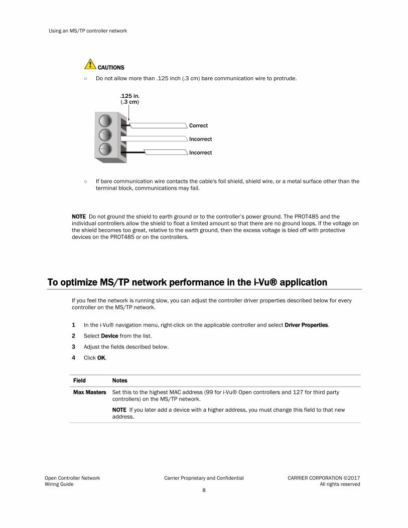
○ Do not allow more than .125 inch (.3 cm) bare communication wire to protrude.
.125 in.(.3 cm)
Correct
Incorrect
Incorrect
○ If bare communication wire contacts the cable's foil shield, shield wire, or a metal surface other than the terminal block, communications may fail.
NOTE Do not ground the shield to earth ground or to the controller’s power ground. The PROT485 and the individual controllers allow the shield to float a limited amount so that there are no ground loops. If the voltage on the shield becomes too great, relative to the earth ground, then the excess voltage is bled off with protective devices on the PROT485 or on the controllers.
To optimize MS/TP network performance in the i-Vu® application
If you feel the network is running slow, you can adjust the controller driver properties described below for every controller on the MS/TP network.
1 In the i-Vu® navigation menu, right-click on the applicable controller and select Driver Properties.
2 Select Device from the list.
3 Adjust the fields described below.
4 Click OK.
Field Notes
Max Masters Set this to the highest MAC address (99 for i-Vu® Open controllers and 127 for third party controllers) on the MS/TP network.
NOTE If you later add a device with a higher address, you must change this field to that new address.
Using an MS/TP controller network
Open Controller Network Carrier Proprietary and Confidential CARRIER CORPORATION ©2017 Wiring Guide All rights reserved 9
Field Notes
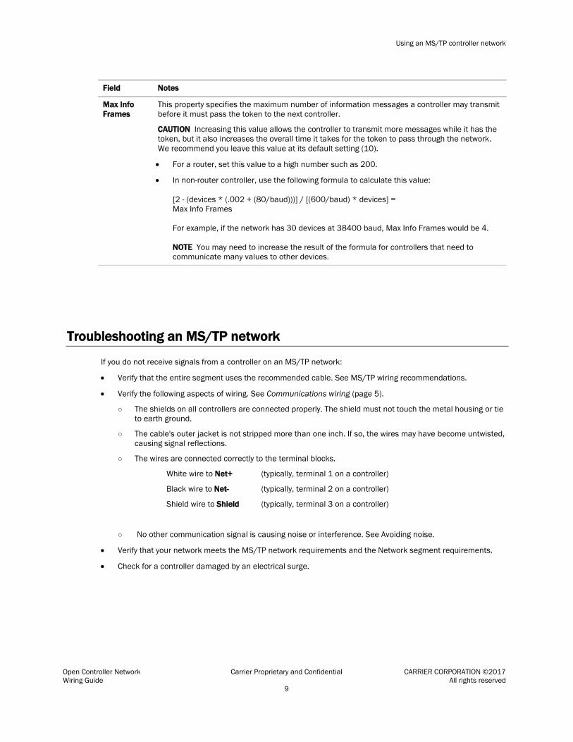
Max Info Frames
This property specifies the maximum number of information messages a controller may transmit before it must pass the token to the next controller.
CAUTION Increasing this value allows the controller to transmit more messages while it has the token, but it also increases the overall time it takes for the token to pass through the network. We recommend you leave this value at its default setting (10).
• For a router, set this value to a high number such as 200.
• In non-router controller, use the following formula to calculate this value: [2 - (devices * (.002 + (80/baud)))] / [(600/baud) * devices] = Max Info Frames For example, if the network has 30 devices at 38400 baud, Max Info Frames would be 4. NOTE You may need to increase the result of the formula for controllers that need to communicate many values to other devices.
Troubleshooting an MS/TP network
If you do not receive signals from a controller on an MS/TP network:
• Verify that the entire segment uses the recommended cable. See MS/TP wiring recommendations.
• Verify the following aspects of wiring. See Communications wiring (page 5).
○ The shields on all controllers are connected properly. The shield must not touch the metal housing or tie to earth ground.
○ The cable's outer jacket is not stripped more than one inch. If so, the wires may have become untwisted, causing signal reflections.
○ The wires are connected correctly to the terminal blocks.
White wire to Net+ (typically, terminal 1 on a controller)
Black wire to Net- (typically, terminal 2 on a controller)
Shield wire to Shield (typically, terminal 3 on a controller)
○ No other communication signal is causing noise or interference. See Avoiding noise.
• Verify that your network meets the MS/TP network requirements and the Network segment requirements.
• Check for a controller damaged by an electrical surge.

Using an MS/TP controller network
Open Controller Network Carrier Proprietary and Confidential CARRIER CORPORATION ©2017 Wiring Guide All rights reserved 10
Locating the problem network segment
The network segment most likely to cause a problem is the segment that: • Contains the most controllers • Covers the longest distance • Contains a variable speed controller, spark igniter, or other major noise source To isolate the problem, divide the questionable segment in half, and add termination at both ends of each segment using a BT485, a 120 Ohm terminator, or the XT controller's End of Net switch set to Yes. If the problems appear on one of the new segments, split this segment in half and repeat this test. Keep splitting the problem segment in half until you identify the cause
Using an oscilloscope to troubleshoot the network
To help diagnose problems with the MS/TP network, use an oscilloscope that has the following features: • 1MHz or greater bandwidth • At least 5 megasamples per second sampling rate • Battery powered (To eliminate oscilloscope's possible connection to ground.)
When capturing waveforms, use the following settings:
Property Recommended setting
Differential mode connections
The scope probe's ground is connected to the Net- connector and the probe's tip is connected to the Net+ connector
Vertical scaling 1–2 volts/division
Horizontal scaling Varies per speed
Coupling mode DC
Trigger level 0.5–1 volt (can be adjusted based on amplitude)
Trigger slope Positive or rising edge to view transition from idle
Negative or falling edge to view transition to idle.

Using an MS/TP controller network
Open Controller Network Carrier Proprietary and Confidential CARRIER CORPORATION ©2017 Wiring Guide All rights reserved 11
When troubleshooting, view a waveform capture from a trouble-free network segment, then compare it with the normal examples below. Look at several frames of the problem segment. Use the figures and descriptions below to discover a possible cause.
Waveform Notes
Normal character waveform with short cable and 2 BT485's
• A normal waveform has sharp vertical transitions at change of bit levels.
• The corners of the waveforms have near-90° transitions.
• For differential connections, the signal is symmetrical above and below the 0-volt line.
• For differential connections, the signal swings from 1–2 volts. If signal swings are <0.75 volt, check for too many terminators on the segment. If the signal swings are >2.5 volts, the segment may not have 2 terminators.

Using an MS/TP controller network
Open Controller Network Carrier Proprietary and Confidential CARRIER CORPORATION ©2017 Wiring Guide All rights reserved 12
Waveform Notes
Normal character waveform with long cable and 2 BT485's
Normal packet waveform with long cable and 2 BT485's

Using an MS/TP controller network
Open Controller Network Carrier Proprietary and Confidential CARRIER CORPORATION ©2017 Wiring Guide All rights reserved 13
Waveform Notes
Excessive capacitance
• The waveform has slow, curving transitions at the change of bit levels. This indicates that the cable may be too long or may not be the recommended type, or a non-Carrier protection device may be on the segment.
• Each negative transition should go at least 0.5 volt below the 0-volt line. With too much capacitance, this will not happen with all negative transitions.
• For differential connections, the waveform is not symmetrical above and below the 0-volt line.
Excessive bias current
• For differential connections, bias level is incorrectly greater than 0.350 volt.

Using an ARCNET controller network
Open Controller Network Carrier Proprietary and Confidential CARRIER CORPORATION ©2017 Wiring Guide All rights reserved 14
For communications on an Open controller network, Carrier can use the ARCNET (Attached Resource Computer Network) protocol which runs at 156K bps over an RS-485 cable.
ARCNET network configurations and requirements
ARCNET network configurations
An ARCNET network can be in a daisy-chain or hybrid configuration if repeaters are used as described in ARCNET network requirements. Each network segment must be in a daisy-chain configuration. See ARCNET Network segment requirements (page 16).
Sample daisy-chain configuration:
Segment
C CC CC CP
TP
C CC CC CP
R TP
C CC CC CP
TP
ControllerC REP485PROT485 Earth Ground R TP
C C RT T
T C
C C C
Segment
Segment
Termination
Using an ARCNET controller network
Using an ARCNET controller network
Open Controller Network Carrier Proprietary and Confidential CARRIER CORPORATION ©2017 Wiring Guide All rights reserved 15
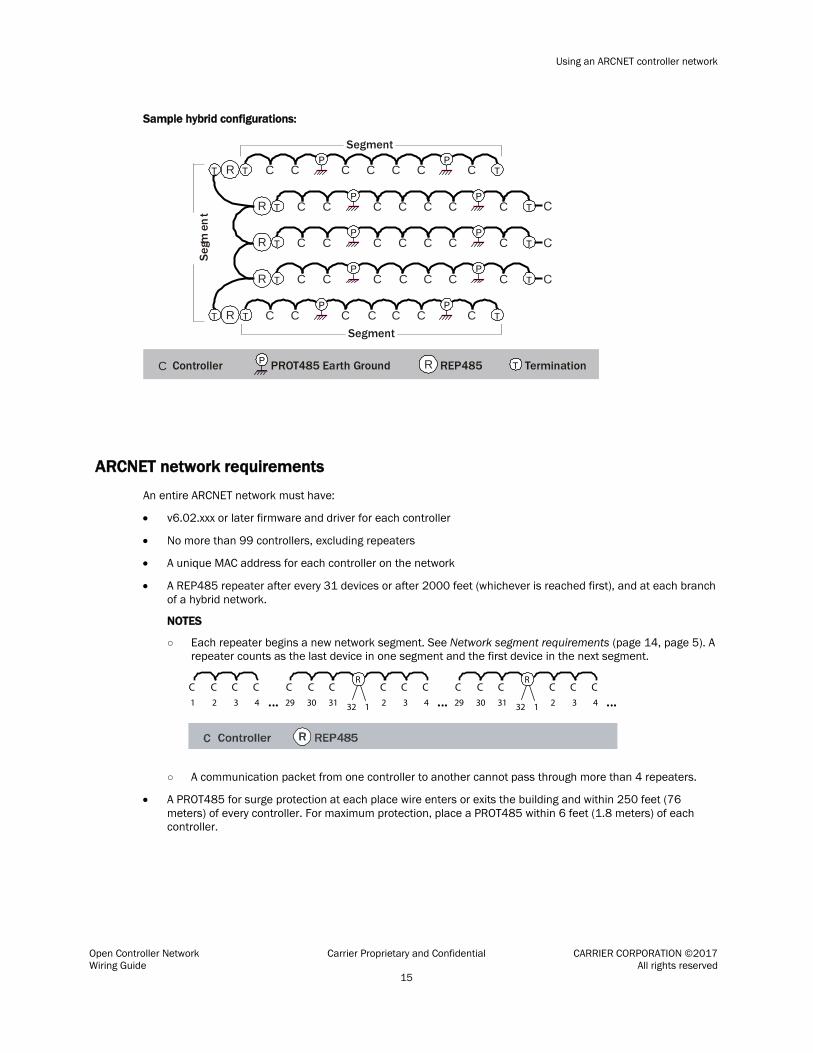
Sample hybrid configurations:
Segment
Segm
ent
Segment
ControllerC REP485PROT485 Earth Ground
C CC CC CP
R TT TP
C CC CC CP
RT TP
C CC CC CP
R T TP
C CC CC CP
R T TP
C CC CC CP
R T TP
R T Termination
T
P
C
C
C
C
C
ARCNET network requirements
An entire ARCNET network must have:
• v6.02.xxx or later firmware and driver for each controller
• No more than 99 controllers, excluding repeaters
• A unique MAC address for each controller on the network
• A REP485 repeater after every 31 devices or after 2000 feet (whichever is reached first), and at each branch of a hybrid network.
NOTES
○ Each repeater begins a new network segment. See Network segment requirements (page 14, page 5). A repeater counts as the last device in one segment and the first device in the next segment.
...C1 2 3 4
C C C21 3 4
C C CC29 30 31 32
C CR
... 21 3 4
C C CC29 30 31 32
C C...
R
○ A communication packet from one controller to another cannot pass through more than 4 repeaters.
• A PROT485 for surge protection at each place wire enters or exits the building and within 250 feet (76 meters) of every controller. For maximum protection, place a PROT485 within 6 feet (1.8 meters) of each controller.

Using an ARCNET controller network
Open Controller Network Carrier Proprietary and Confidential CARRIER CORPORATION ©2017 Wiring Guide All rights reserved 16
ARCNET network segment requirements
An ARCNET network can consist of multiple network segments. See the samples in ARCNET network configurations (page 14). Each segment of an ARCNET network must:
• Be wired in a daisy-chain configuration.
• Be no longer than 2000 feet (610 meters).
• Have 32 or fewer devices (controllers and repeaters).
• Have one of the following:
○ The End of Net switch set to Yes on the XT controller that is at the end of the network segment. This adds bias and prevent signal distortions due to echoing.
○ A BT485 at each end (unless the segment is less than 10 feet [3 meters] long) to add bias and prevent signal distortions due to echoing. See What is the BT485? (page 25).
NOTE To attach a 120 Ohm terminator, turn off the controller’s power, then attach the terminator to the Net + and Net – terminals.
ARCNET communications wiring
Carrier controllers with the appropriate firmware and drivers can communicate on a high-speed 156 kbps controller network.
Avoiding noise
Avoid running communication wires or sensor input wires next to AC power wires or the controller's relay output wires. These can be sources of noise that can affect signal quality.
Common sources of noise are:
Spark igniters Radio transmitters Variable speed drives Electric motors (> 1hp) Generators Relays Transformers
Induction heaters Large contactors (i.e., motor starters) Video display devices Lamp dimmers Fluorescent lights Parallel runs with power lines Other electronic modules
If noise is a problem and you cannot move the wiring, use ferrite clamp-on chokes on the cabling to improve signal quality.

Using an ARCNET controller network
Open Controller Network Carrier Proprietary and Confidential CARRIER CORPORATION ©2017 Wiring Guide All rights reserved 17
ARCNET wiring specifications
Below are the specifications for ARCNET wiring. The wire jacket and UL temperature rating specifications list two acceptable alternatives. Halar has a higher temperature rating and a tougher outer jacket than SmokeGard, and it is appropriate for use in applications where you are concerned about abrasion. Halar is also less likely to crack in extremely low temperatures.
NOTE Use the specified type of wire and cable for maximum signal integrity.
Description Single twisted pair, low capacitance (12pF), CL2P, 22 AWG (7x30), TC foam FEP, plenum rated cable
Conductor 22 AWG (7x30) stranded copper (tin plated) 0.030 in. (0.762 mm) O.D.
NOTE 24 AWG can be used for segments <200 ft. (6.7 m).
Insulation Foamed FEP 0.015 in. (0.381 mm) wall 0.060 in. (1.524 mm) O.D.
Color code Black/white
Twist lay 2 in. (50.8 mm) lay on pair 6 twists/foot (20 twists/meter) nominal
Shielding Aluminum/Mylar shield with 24 AWG (7x32) TC drain wire
Jacket SmokeGard (SmokeGard PVC) 0.021 in. (0.5334 mm) wall 0.175 in. (4.445 mm) O.D.
Halar (E-CTFE) 0.010 in. (0.254 mm) wall 0.144 in. (3.6576 mm) O.D.
DC resistance 15.2 Ohms/1000 feet (50 Ohms/km) nominal
Capacitance 12.5 pF/ft (41 pF/meter) nominal conductor to conductor
Characteristic impedance 100 Ohms nominal
Weight 12 lb/1000 feet (17.9 kg/km)
UL temperature rating SmokeGard 167°F (75°C)
Halar -40 to 302°F (-40 to 150°C)
Voltage 300 Vac, power limited
Listing UL: NEC CL2P, or better
See MS/TP and ARCNET wring specifications and recommended vendors (page 36).

Using an ARCNET controller network
Open Controller Network Carrier Proprietary and Confidential CARRIER CORPORATION ©2017 Wiring Guide All rights reserved 18
To wire the communication cable
1 Partially cut, then bend and pull off 1" of the outer jacket of the cable(s). Do not nick the inner insulation.
Inner insulation
Outer jacket
Foil
1 in.(2.5 cm)
.25 in.(.6 cm)
2 Strip about .25 inch (.6 cm) of the inner insulation from each wire.
3 If wiring two cables to the controller, twist together the shield wires from both cables.
4 Insert the wires into the terminal block.
Shield
CAUTIONS
○ Do not allow more than .125 inch (.3 cm) bare communication wire to protrude.
.125 in.(.3 cm)
Correct
Incorrect
Incorrect
○ If bare communication wire contacts the cable's foil shield, shield wire, or a metal surface other than the terminal block, communications may fail.

Using an ARCNET controller network
Open Controller Network Carrier Proprietary and Confidential CARRIER CORPORATION ©2017 Wiring Guide All rights reserved 19
NOTE Do not ground the shield to earth ground or to the controller’s power ground. The PROT485 and the individual controllers allow the shield to float a limited amount so that there are no ground loops. If the voltage on the shield becomes too great relative to the earth ground, then the excess voltage is bled off with protective devices on the PROT485 or on the controllers.
Token passing on an ARCNET network
On an ARCNET network, each controller's ARCNET coprocessor controls the token passing scheme. The token passes rapidly from controller to controller without intervention. Because the token passes only to controllers that exist on the network, controllers do not need to be sequentially addressed.
If a controller does not respond to its token, the controller drops from the loop and does not receive its token again until the network is reconfigured. A network reconfiguration allows controllers that were not participating in the token passing to enter their address into the token passing loop. This process takes about 3 seconds. If a controller has just been powered up or has not received the token for about 13 seconds, the controller initiates a network reconfiguration.
Each controller can send only one data packet each time it gets the token, then the controller passes the token. No controller can keep the token. The longest time a controller typically waits for its token is 0.5 seconds.
Workstations can communicate with the ARCNET network without stopping the token. The controllers can continue to communicate global points, colors, alarms, and heat/cool requests even while a workstation transfers memory to a controller.
Troubleshooting an ARCNET network
If the i-Vu® application cannot communicate with one or more controllers on an ARCNET network or if the network continually reconfigures, you have a network problem and must determine if the problem is caused by: • The network wiring • The network configuration • A particular controller • The network's environment
ARCNET reconfigurations
An ARCNET network normally reconfigures itself when a controller is added to or taken off the network. For example, turning a controller’s power off or on. If communication with controllers is intermittent or downloads are excessively slow, see if the network is continually reconfiguring. To do this, check any controller’s:
• Transmit and Receive LED’s. These turn off for 1 second each time the network reconfigures.
• Modstat to see if an unexpected number appears in the Total field shown below. ARC156 reconfigurations during the last hour (cleared upon reset): Total . . . . . . . . . . . . . . . . 15

Using an ARCNET controller network
Open Controller Network Carrier Proprietary and Confidential CARRIER CORPORATION ©2017 Wiring Guide All rights reserved 20
Locating the problem
NOTE If the network was working correctly and then began to have problems, consider any recent changes to the network as a possible source of the problem.
Follow the steps below until you locate the problem.
1 Verify that the ARCNET network uses the recommended cable. See ARCNET wiring specifications (page 16).
2 Check drawings of the completed network to verify that it meets the ARCNET network requirements (page 15) and the ARCNET network segment requirements (page 16).
3 Try to obtain a modstat for each controller.
○ If the Initiated by this node field shows a number, check the network wiring connection for that controller, the controller with the next lower MAC address, and all controllers located between these two controllers. ARC156 reconfigurations during the last hour (cleared upon reset): Total . . . . . . . . . . . . . . . . 15 Initiated by this node. . . . . . . . 15
○ If you cannot obtain a modstat for a controller, check the controller's LEDs to see if it is running correctly. (See the controller's Installation and Start-up Guide for a description of its LEDs.)
If the controller's LEDs do not indicate a problem with the controller, check the controller's network wiring connection.
To check a controller’s network wiring connection, verify that:
a) The shield wire is connected properly. The shield must not touch the metal housing or tie to earth ground.
b) The cable's outer jacket is not stripped more than one inch. If so, the wires may have become untwisted, causing noise.
c) The wires are connected correctly to the terminal blocks. Black wire to Net - White wire to Net + Shield wire to Shield
d) No external source is causing noise or interference. See Avoiding noise (page 5).
4 Isolate the problem network segment.
a) If the network has a repeater, disconnect it, then check the Transmit and Receive LED's or a modstat of a controller on each network segment to determine which segment is reconfiguring. If the network has multiple repeaters, perform this step for one repeater at a time.
b) Divide the questionable segment in half, and add termination at both ends of each segment using a BT485, a 120 Ohm terminator, or the XT controller's End of Net switch set to Yes.
c) Determine which of the new segments has the problem, then repeat step a. on that segment.
d) Continue splitting each problem segment in half until you identify the cause.
Using an ARCNET controller network
Open Controller Network Carrier Proprietary and Confidential CARRIER CORPORATION ©2017 Wiring Guide All rights reserved 21
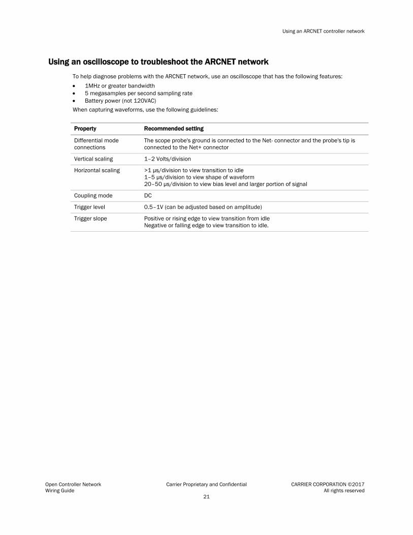
Using an oscilloscope to troubleshoot the ARCNET network
To help diagnose problems with the ARCNET network, use an oscilloscope that has the following features: • 1MHz or greater bandwidth • 5 megasamples per second sampling rate • Battery power (not 120VAC) When capturing waveforms, use the following guidelines:
Property Recommended setting
Differential mode connections
The scope probe's ground is connected to the Net- connector and the probe's tip is connected to the Net+ connector
Vertical scaling 1–2 Volts/division
Horizontal scaling >1 µs/division to view transition to idle 1–5 µs/division to view shape of waveform 20–50 µs/division to view bias level and larger portion of signal
Coupling mode DC
Trigger level 0.5–1V (can be adjusted based on amplitude)
Trigger slope Positive or rising edge to view transition from idle Negative or falling edge to view transition to idle.

Using an ARCNET controller network
Open Controller Network Carrier Proprietary and Confidential CARRIER CORPORATION ©2017 Wiring Guide All rights reserved 22
When troubleshooting, view a waveform capture from a trouble-free network segment, then compare it with the normal examples below. Look at several frames of the problem segment. Use the figures and descriptions below to discover a possible cause.
Waveform Notes
Normal character waveform with short cable and 2 BT485's
• A normal waveform has sharp vertical transitions at change of bit levels.
• The corners of the waveforms have near-90° transitions.
• For differential connections, the signal is symmetrical above and below the 0-volt line.
• For differential connections, the signal swings from 1–2 volts. If signal swings are <0.75 volt, check for too many terminators on the segment. If the signal swings are >2.5 volts, the segment may not have 2 terminators.

Using an ARCNET controller network
Open Controller Network Carrier Proprietary and Confidential CARRIER CORPORATION ©2017 Wiring Guide All rights reserved 23
Waveform Notes
Normal character waveform with long cable and 2 BT485's
Normal packet waveform with long cable and 2 BT485's

Using an ARCNET controller network
Open Controller Network Carrier Proprietary and Confidential CARRIER CORPORATION ©2017 Wiring Guide All rights reserved 24
Waveform Notes
Excessive capacitance
• The waveform has slow, curving transitions at the change of bit levels. This indicates that the cable may be too long or may not be the recommended type, or a non-Carrier protection device may be on the segment.
• Each negative transition should go at least 0.5 volt below the 0-volt line. With too much capacitance, this will not happen with all negative transitions.
• For differential connections, the waveform is not symmetrical above and below the 0-volt line.
Excessive bias current
• For differential connections, bias level is incorrectly greater than 0.350 volt.
What is the BT485?
Open Controller Network Carrier Proprietary and Confidential CARRIER CORPORATION ©2017 Wiring Guide All rights reserved 25
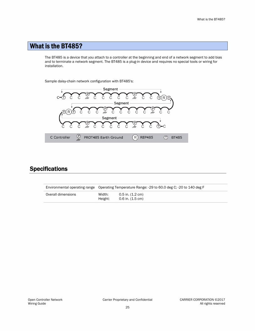
The BT485 is a device that you attach to a controller at the beginning and end of a network segment to add bias and to terminate a network segment. The BT485 is a plug-in device and requires no special tools or wiring for installation.
Sample daisy-chain network configuration with BT485's:
Specifications
Environmental operating range Operating Temperature Range: -29 to 60.0 deg C; -20 to 140 deg F
Overall dimensions Width: Height:
0.5 in. (1.2 cm) 0.6 in. (1.5 cm)
What is the BT485?
What is the BT485?
Open Controller Network Carrier Proprietary and Confidential CARRIER CORPORATION ©2017 Wiring Guide All rights reserved 26
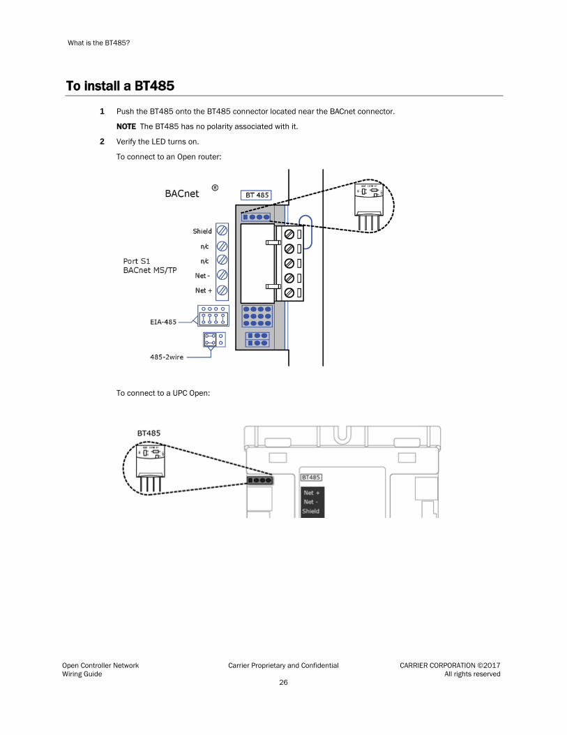
To install a BT485
1 Push the BT485 onto the BT485 connector located near the BACnet connector.
NOTE The BT485 has no polarity associated with it.
2 Verify the LED turns on.
To connect to an Open router:
To connect to a UPC Open:

What is a PROT485?
Open Controller Network Carrier Proprietary and Confidential CARRIER CORPORATION ©2017 Wiring Guide All rights reserved 27
The PROT485 is a device that protects against large electrical surges on communication networks.
Recommended placements for a PROT485:
• At each place wire enters or exits the building
• Install at least one PROT485 within 250 feet (76 meters) of every controller. For maximum protection, place a PROT485 within 6 feet (1.8 meters) of each controller.
Sample daisy-chain controller network configuration:
Segment
C CC CC CP
TP
C CC CC CP
R TP
C CC CC CP
TP
ControllerC REP485PROT485 Earth Ground R TP
C C RT T
T C
C C C
Segment
Segment
Termination
Specifications
Environmental operating range
-20 to 140°F (-29 to 60°C), 10–90% relative humidity, non-condensing
Protection The PROT485 has two replaceable 0.5 A fuses protecting the Fused connection:
F1, type 3AG, 250 Vac, 0.5 A, T (time-lag) F2, type 3AG, 250 Vac, 0.5 A, T (time-lag)
The protection element is a SIDACtor, transient voltage suppression component. This solid-state component shunts energy to ground.
Overall dimensions Width: Height:
4 in. (10.16 cm) 4 in. (10.16 cm)
Listed by CE
What is a PROT485?

What is a PROT485?
Open Controller Network Carrier Proprietary and Confidential CARRIER CORPORATION ©2017 Wiring Guide All rights reserved 28
To mount a PROT485
CAUTION If the equipment is used in a manner not specified by the manufacturer, the protection provided by the equipment may be impaired. When you handle the PROT485:
○ Do not contaminate the printed circuit board with fingerprints, moisture, or any foreign material.
○ Do not touch components or leads.
○ Handle the board by its edges.
○ Isolate from high voltage or electrostatic discharge.
○ Ensure that you are properly grounded.
Provide at least 1.5 in. (3.8 cm) clearance from each edge of the PROT485 for wiring.
1 Remove PROT485 from the included snap track.
2 Mount the snap track using self-drilling screws. Drill directly into the plastic near the edges of the snap track so that the screws will be visible when you install the PROT485. This prevents loose screws from shorting out the back of the board.
3 Mount the PROT485 on the snap track by pushing it firmly into the grooves.
To wire a PROT485 for communications
WARNING Do not apply line voltage (mains voltage) to this device's ports or terminals.
1 Check the communications wiring for shorts and grounds.
2 Connect the communication wires to the appropriate connectors as follows:
○ Use the Shared and Unfused connectors for wiring that leads to other controllers within a building.
+–
Shield
Shield
+
–
Fused:Wiring coming from outside
of building
Shared connection:Fused or unfused
Unfused:Use for
inside wiring
EARTH GROUND EARTH GROUND
To controllersinside thebuilding
Wiring leavingthe building
What is a PROT485?
Open Controller Network Carrier Proprietary and Confidential CARRIER CORPORATION ©2017 Wiring Guide All rights reserved 29
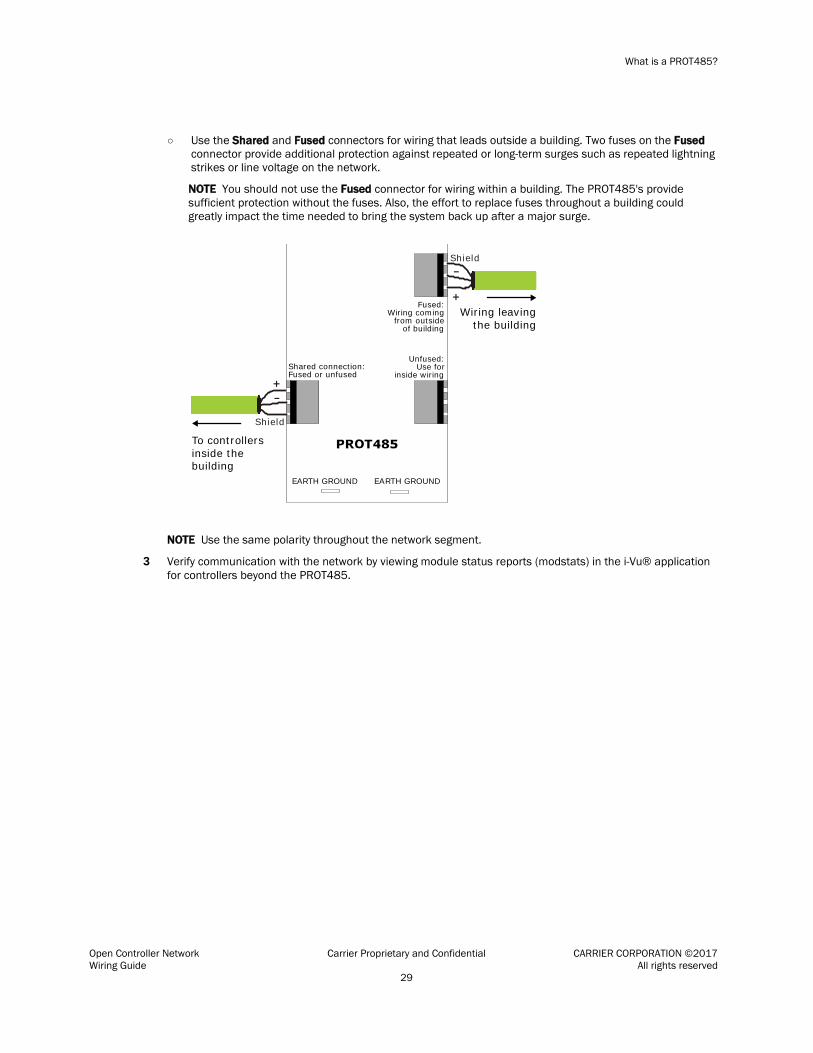
○ Use the Shared and Fused connectors for wiring that leads outside a building. Two fuses on the Fused connector provide additional protection against repeated or long-term surges such as repeated lightning strikes or line voltage on the network.
NOTE You should not use the Fused connector for wiring within a building. The PROT485's provide sufficient protection without the fuses. Also, the effort to replace fuses throughout a building could greatly impact the time needed to bring the system back up after a major surge.
+–
Shield
Shield
+
–
Fused:Wiring coming from outside
of building
Shared connection:Fused or unfused
Unfused:Use for
inside wiring
EARTH GROUND EARTH GROUND
To controllersinside thebuilding
Wiring leavingthe building
NOTE Use the same polarity throughout the network segment.
3 Verify communication with the network by viewing module status reports (modstats) in the i-Vu® application for controllers beyond the PROT485.

What is a PROT485?
Open Controller Network Carrier Proprietary and Confidential CARRIER CORPORATION ©2017 Wiring Guide All rights reserved 30
Grounding the controller network
Use 12 AWG grounding wire, no more than 6 feet (1.8 meters) long.
Connect grounding wire(s) to the PROT485's Earth Ground connectors with a 3M Corporation female spade connector part number FD114-250C or equivalent.
If the controller is within 6 feet (1.8 meters) of the PROT485, connect one ground wire to the controller and another ground wire to earth ground.
If the controller is more than 6 feet (1.8 meters) from the PROT485, connect a ground wire to earth ground.

What is a REP485?
Open Controller Network Carrier Proprietary and Confidential CARRIER CORPORATION ©2017 Wiring Guide All rights reserved 31
The REP485 is a repeater that boosts communication signals over lengthy runs of wire. It has two bidirectional, optically isolated ports that can communicate at speeds from 1200 bps to 156 kbps. You can use the REP485 on any BACnet communications network using EIA-485, like MS/TP networks. A REP485 counts as two devices, one in each of its associated network segments.
Place a REP485 after every 31 controllers, after 2000 feet (whichever is reached first), and at each branch of a hybrid network. Each repeater begins a new network segment. You can wire a maximum of four REP485's in series. See Sample network configurations using REP485's.
What is a REP485?

What is a REP485?
Open Controller Network Carrier Proprietary and Confidential CARRIER CORPORATION ©2017 Wiring Guide All rights reserved 32
Specifications
Power 24 Vac ±10%, 250 mA (6.0 VA), 50–60 Hz
Ports Net A and B are both EIA-485 (optically isolated)
Environmental operating range
0 to 130°F (-17.8 to 54.4°C), 5–95% relative humidity, non-condensing
Overall dimensions Width: Height:
4 in. (10.16 cm) 4 in. (10.16 cm)
Listed by UL-916 (PAZX), cUL-916 (PAZX7), CE
Sample network configurations using MS/TP's
Daisy-chain network configuration:
Segment
C CC CC CP
TP
C CC CC CP
R TP
C CC CC CP
TP
ControllerC REP485PROT485 Earth Ground R TP
C C RT T
T C
C C C
Segment
Segment
Termination

What is a REP485?
Open Controller Network Carrier Proprietary and Confidential CARRIER CORPORATION ©2017 Wiring Guide All rights reserved 33
Hybrid network configurations:
Segment
Segm
ent
Segment
ControllerC REP485PROT485 Earth Ground
C CC CC CP
R TT TP
C CC CC CP
RT TP
C CC CC CP
R T TP
C CC CC CP
R T TP
C CC CC CP
R T TP
R T Termination
T
P
C
C
C
C
C
To mount a REP485
CAUTION If the equipment is used in a manner not specified by the manufacturer, the protection provided by the equipment may be impaired. When you handle the REP485:
○ Do not contaminate the printed circuit board with fingerprints, moisture, or any foreign material.
○ Do not touch components or leads.
○ Handle the board by its edges.
○ Isolate from high voltage or electrostatic discharge.
○ Ensure that you are properly grounded.
Provide at least 1.5 in. (3.8 cm) clearance from each edge of the REP485 for wiring.
1 Remove REP485 from the included snap track.
2 Mount the snap track using self-drilling screws. Drill directly into the plastic near the edges of the snap track so that the screws will be visible when you install the REP485. This prevents loose screws from shorting out the back of the board.
3 Mount the REP485 on the snap track by pushing it firmly into the grooves.

What is a REP485?
Open Controller Network Carrier Proprietary and Confidential CARRIER CORPORATION ©2017 Wiring Guide All rights reserved 34
To wire a REP485 for power
CAUTIONS
• The REP485 is powered by a Class 2 power source. Take appropriate isolation measures when mounting it in a control panel where non-Class 2 circuits are present.
• Carrier Open controllers can share a power supply as long as you: • Maintain the same polarity. ○ Use the power supply only for Carrier controllers.
1 Place the REP485’s power jumper in the Off position.
2 Remove power from the 24 Vac transformer.
3 Pull the screw terminal connector from the REP485's power connector.
4 Connect the transformer wires to the screw terminal connector.
5 Apply power to the transformer.
6 Measure the voltage at the REP485’s power input terminals to verify that the voltage is within the operating range of 21.6–26.4 Vac.
7 Connect the Earth GND terminal with a piece of 12AWG wire (no longer than 2 feet [0.6 m]) to a verified earth ground connection such as a nearby metal water pipe, metal building structure, or the panel. Use female spade connector part # FD114-250C (3M Corporation) or equivalent.
8 Insert the screw terminal connector into the REP485's power connector.
9 Place the REP485’s power jumper in the On position. The Power LED lights when the REP485 has power.
To wire a REP485 for communications
WARNING Do not apply line voltage (mains voltage) to this device's ports or terminals.
NOTE If the REP485 begins or ends a network segment, add a BT485 to the side of the REP485 where the network is connected to terminate the network and add bias. See "T" on the sample network configurations (page 32).
1 Place the REP485's power jumper in the Off position.
2 Check the communications wiring for shorts and grounds.
3 Connect the communications wiring to the REP485's Network A and Network B connectors.
NOTE Use the same polarity throughout the network segment.
4 Place the REP485's power jumper in the On position.
5 Verify communication with the network by viewing Module Status reports (Modstats) in the i-Vu® interface for controllers beyond the REP485. LED2 and LED3 blink when receiving data.

What is a REP485?
Open Controller Network Carrier Proprietary and Confidential CARRIER CORPORATION ©2017 Wiring Guide All rights reserved 35
REP485 LEDs
The LED's on the REP485 show the status of certain functions.
If this LED is on... Status is...
Power The board has power
LED2 Net A is receiving data.
LED3 Net B is receiving data.
Appendix: MS/TP and ARCNET wiring specifications and recommended vendors
Open Controller Network Carrier Proprietary and Confidential CARRIER CORPORATION ©2017 Wiring Guide All rights reserved 36
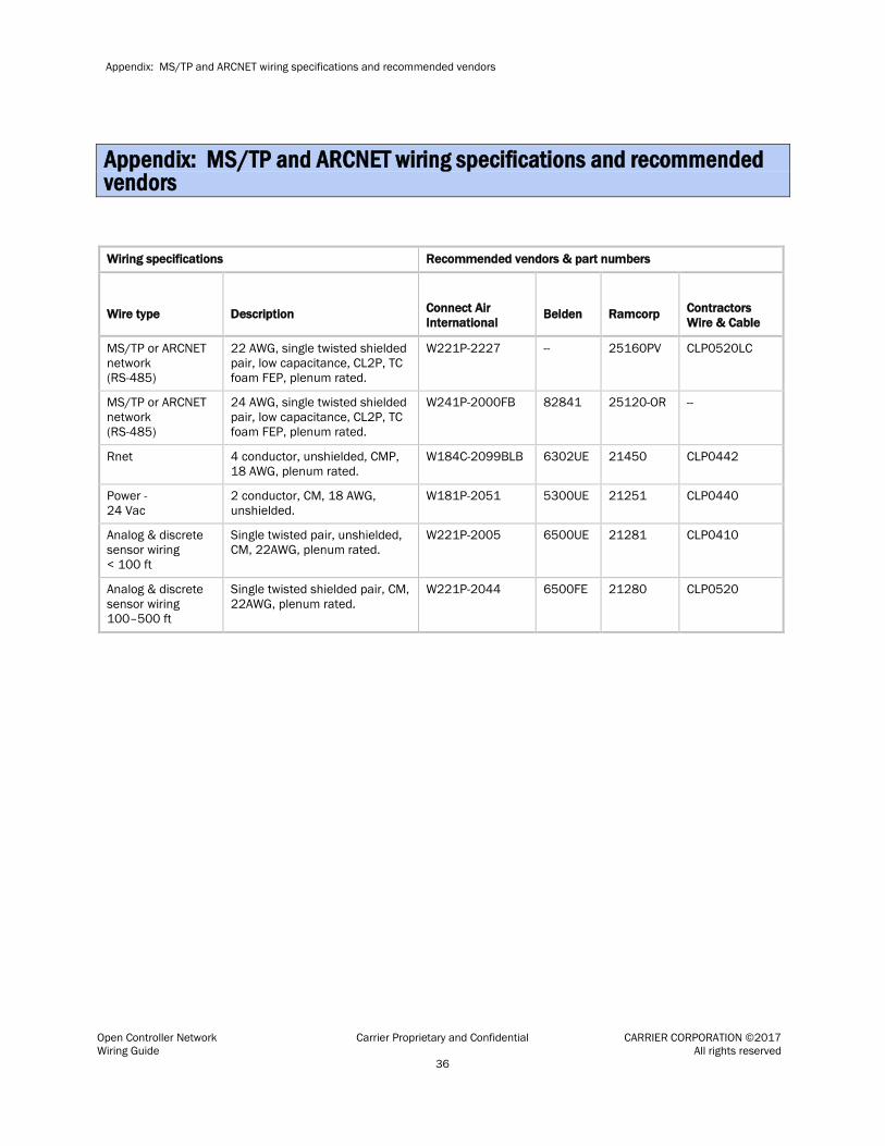
Wiring specifications Recommended vendors & part numbers
Wire type
Description
Connect Air International
Belden
Ramcorp
Contractors Wire & Cable
MS/TP or ARCNET network (RS-485)
22 AWG, single twisted shielded pair, low capacitance, CL2P, TC foam FEP, plenum rated.
W221P-2227 -- 25160PV CLP0520LC
MS/TP or ARCNET network (RS-485)
24 AWG, single twisted shielded pair, low capacitance, CL2P, TC foam FEP, plenum rated.
W241P-2000FB 82841 25120-OR --
Rnet 4 conductor, unshielded, CMP, 18 AWG, plenum rated.
W184C-2099BLB 6302UE 21450 CLP0442
Power - 24 Vac
2 conductor, CM, 18 AWG, unshielded.
W181P-2051 5300UE 21251 CLP0440
Analog & discrete sensor wiring < 100 ft
Single twisted pair, unshielded, CM, 22AWG, plenum rated.
W221P-2005 6500UE 21281 CLP0410
Analog & discrete sensor wiring 100–500 ft
Single twisted shielded pair, CM, 22AWG, plenum rated.
W221P-2044 6500FE 21280 CLP0520
Appendix: MS/TP and ARCNET wiring specifications and recommended vendors

Document revision history
Open Controller Network Carrier Proprietary and Confidential CARRIER CORPORATION ©2017 Wiring Guide All rights reserved 37
Important changes to this document are listed below. Minor changes such as typographical or formatting errors are not listed.
Date Topic Change description Code* 8/23/17 To wire a REP485 for communications Changed NOTE to say connect BT485s to REP485, not
adjacent controllers. X-O-F-TS
* For internal use only
Document revision history


CARRIER CORPORATION ©2017 A member of the United Technologies Corporation family · Stock symbol UTX · Catalog No. 11-808-461-01 · 8/23/2017