CANTILEVER REPLACEMENT - kdotapp.ksdot.org · mount on psst post with coupler and footing ... or do...
17
Pl otted By: k a r e np Pl ot L ocati on: KA478701 - T itl e S h ee t . dgn F il e: Pl ot Date: 19 - S EP- 2018 09 : 00 STATE KANSAS PROJECT NO. YEAR TOTAL SHEETS SHEET NO. DEPARTMENT OF TRANSPORTATION STATE OF KANSAS KANSAS PROJECT JOHNSON COUNTY PROJ. NO. 435-105 KA-4787-01 I-435 CANTILEVER REPLACEMENT P O P . 7118 P O P . 3554 B. N. B onn e r S p r i ng s 7 2 4 40 32 70 435 E d w a r d s v ill e 2019 435-105 KA-4787-01 Sheet No. Sheet No. Cantilever Project Location 1 1 Traffic Control Sign Structure Replacement 17 See Sheet 3 for the Sheet Index construction using existing lanes Traffic is to be carried through CADc on f o r m Ce r ti f y T h i s F il e CADconform Certify This File REVIEWED FOR GENERAL COMPLIANCE WITH PLANS AND SPECIFICATIONS ONLY DETAIL DIMENSIONS NOT CHECKED RECOMMENDED FOR APPROVAL Chief of Bureau of Structures and Geotechnical Services APPROVED Deputy Secretary and State Transportation Engineer Oct 01, 2018
Transcript of CANTILEVER REPLACEMENT - kdotapp.ksdot.org · mount on psst post with coupler and footing ... or do...
Plotte
d
By:
karenp
Plot
Locatio
n:
KA478701-Title
Sheet.dgn
File:
Plot
Date:
19-S
EP-2018 09:0
0
STATE
KANSAS
PROJECT NO. YEAR
TOTAL
SHEETSSHEET NO.
DEPARTMENT OF TRANSPORTATION
STATE OF KANSAS
KANSAS PROJECT
JOHNSON COUNTY
PROJ. NO. 435-105 KA-4787-01
I-435
CANTILEVER REPLACEMENT
POP. 7118
POP. 3554
B.N.
Bonner Springs7
2440
32
70
435
Edwardsville
2019
435-105 KA-4787-01
Sheet No.Sheet No.
Cantilever
Project Location
1
1
Traffic Control
Sign Structure Replacement
17
See Sheet 3 for the Sheet Index
construction using existing lanes
Traffic is to be carried through
CA
Dconform C
ertify T
his File
CADconform Certify This File
REVIEWED FOR GENERAL COMPLIANCEWITH PLANS AND SPECIFICATIONS ONLYDETAIL DIMENSIONS NOT CHECKED
RECOMMENDED FOR APPROVAL
Chief of Bureau of Structuresand Geotechnical Services
APPROVED
Deputy Secretary andState Transportation Engineer
Oct 01, 2018
Kansas Turnpike AuthorityKansas Turnpike Authority
KANSAS DEPARTMENT OF TRANSPORTATION
SHEETS
TOTALSHEET NO.
KANSAS
STATE YEAR
Signature Seal Sheet
PROJECT N0.
RD048
Name:
Co. Name:
Plan Section:
435-105 KA-4787-01 22019
CA
Dconform C
ertify T
his File
CADconform Certify This File
D
ESNECI
L
SASNA
K
17957
NO
SRETEP .S.M
N
ER
AK
RE
E
NIGNE LANOIS
SE
F
OR
P
Sep 19, 2018
1-17
KDOT - BSGS
Karen Peterson
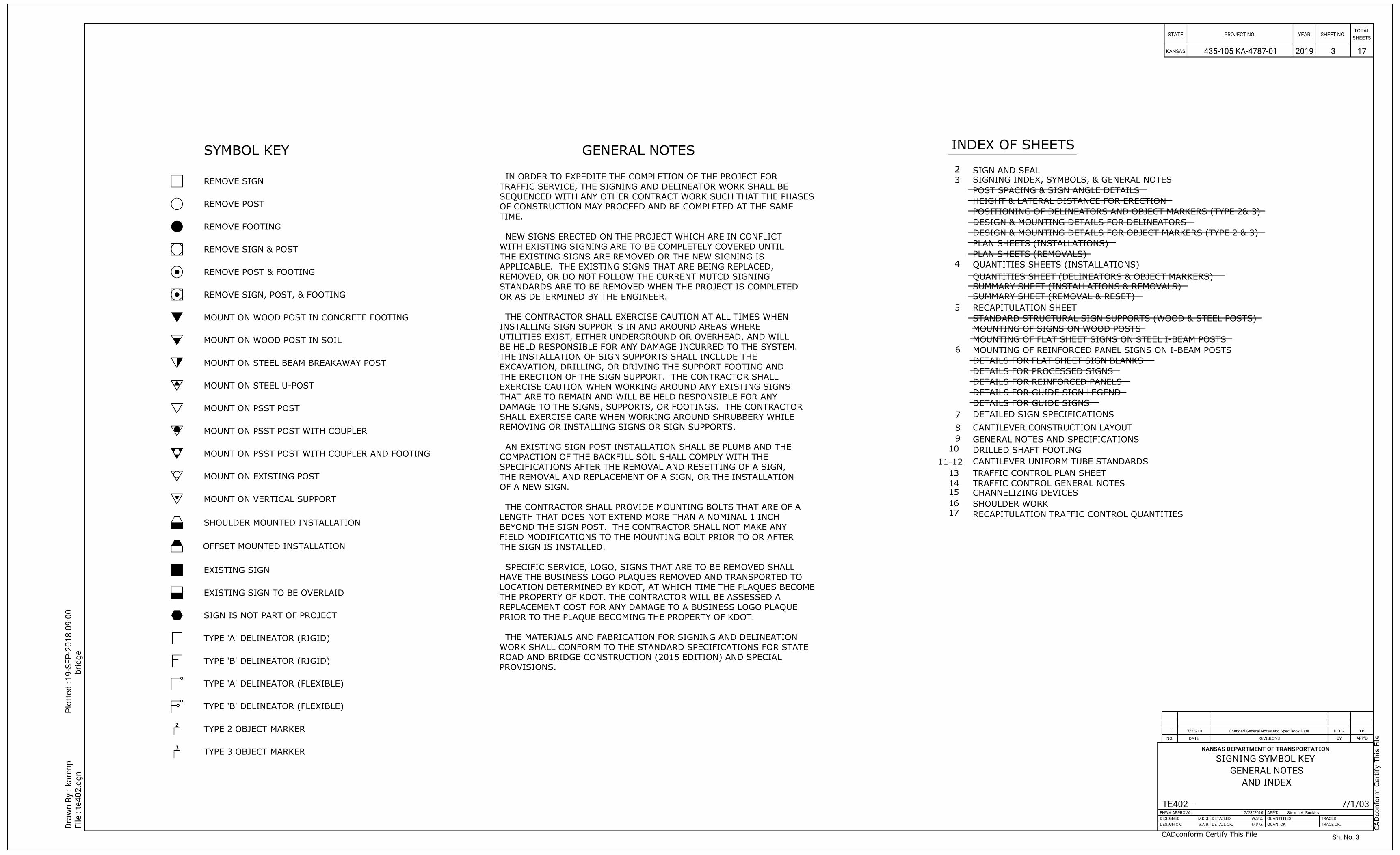
REMOVE SIGN
REMOVE POST
REMOVE FOOTING
REMOVE SIGN & POST
REMOVE POST & FOOTING
REMOVE SIGN, POST, & FOOTING
MOUNT ON WOOD POST IN CONCRETE FOOTING
MOUNT ON WOOD POST IN SOIL
MOUNT ON STEEL BEAM BREAKAWAY POST
MOUNT ON STEEL U-POST
MOUNT ON EXISTING POST
MOUNT ON VERTICAL SUPPORT
SHOULDER MOUNTED INSTALLATION
OFFSET MOUNTED INSTALLATION
EXISTING SIGN
EXISTING SIGN TO BE OVERLAID
TYPE 'A' DELINEATOR (RIGID)
SIGN IS NOT PART OF PROJECT
TYPE 'B' DELINEATOR (RIGID)
TYPE 'A' DELINEATOR (FLEXIBLE)
TYPE 'B' DELINEATOR (FLEXIBLE)
TYPE 2 OBJECT MARKER
TYPE 3 OBJECT MARKER
SYMBOL KEY
POST SPACING & SIGN ANGLE DETAILS
HEIGHT & LATERAL DISTANCE FOR ERECTION
DETAILS FOR PROCESSED SIGNS
DETAILED SIGN SPECIFICATIONS
MOUNTING OF FLAT SHEET SIGNS ON STEEL I-BEAM POSTS
SIGNING INDEX, SYMBOLS, & GENERAL NOTES
PLAN SHEETS (REMOVALS)
POSITIONING OF DELINEATORS AND OBJECT MARKERS (TYPE 2& 3)
DESIGN & MOUNTING DETAILS FOR OBJECT MARKERS (TYPE 2 & 3)
DESIGN & MOUNTING DETAILS FOR DELINEATORS
RECAPITULATION SHEET
QUANTITIES SHEETS (INSTALLATIONS)
QUANTITIES SHEET (DELINEATORS & OBJECT MARKERS)
STANDARD STRUCTURAL SIGN SUPPORTS (WOOD & STEEL POSTS)
MOUNTING OF SIGNS ON WOOD POSTS
DETAILS FOR FLAT SHEET SIGN BLANKS
DETAILS FOR GUIDE SIGN LEGEND
DETAILS FOR GUIDE SIGNS
PLAN SHEETS (INSTALLATIONS)
DETAILS FOR REINFORCED PANELS
MOUNTING OF REINFORCED PANEL SIGNS ON I-BEAM POSTS
INDEX OF SHEETSGENERAL NOTES
MOUNT ON PSST POST WITH COUPLER
MOUNT ON PSST POST WITH COUPLER AND FOOTING
MOUNT ON PSST POST
PROVISIONS.
ROAD AND BRIDGE CONSTRUCTION (2015 EDITION) AND SPECIAL
WORK SHALL CONFORM TO THE STANDARD SPECIFICATIONS FOR STATE
THE MATERIALS AND FABRICATION FOR SIGNING AND DELINEATION
PRIOR TO THE PLAQUE BECOMING THE PROPERTY OF KDOT.
REPLACEMENT COST FOR ANY DAMAGE TO A BUSINESS LOGO PLAQUE
THE PROPERTY OF KDOT. THE CONTRACTOR WILL BE ASSESSED A
LOCATION DETERMINED BY KDOT, AT WHICH TIME THE PLAQUES BECOME
HAVE THE BUSINESS LOGO PLAQUES REMOVED AND TRANSPORTED TO
SPECIFIC SERVICE, LOGO, SIGNS THAT ARE TO BE REMOVED SHALL
THE SIGN IS INSTALLED.
FIELD MODIFICATIONS TO THE MOUNTING BOLT PRIOR TO OR AFTER
BEYOND THE SIGN POST. THE CONTRACTOR SHALL NOT MAKE ANY
LENGTH THAT DOES NOT EXTEND MORE THAN A NOMINAL 1 INCH
THE CONTRACTOR SHALL PROVIDE MOUNTING BOLTS THAT ARE OF A
OF A NEW SIGN.
THE REMOVAL AND REPLACEMENT OF A SIGN, OR THE INSTALLATION
SPECIFICATIONS AFTER THE REMOVAL AND RESETTING OF A SIGN,
COMPACTION OF THE BACKFILL SOIL SHALL COMPLY WITH THE
AN EXISTING SIGN POST INSTALLATION SHALL BE PLUMB AND THE
REMOVING OR INSTALLING SIGNS OR SIGN SUPPORTS.
SHALL EXERCISE CARE WHEN WORKING AROUND SHRUBBERY WHILE
DAMAGE TO THE SIGNS, SUPPORTS, OR FOOTINGS. THE CONTRACTOR
THAT ARE TO REMAIN AND WILL BE HELD RESPONSIBLE FOR ANY
EXERCISE CAUTION WHEN WORKING AROUND ANY EXISTING SIGNS
THE ERECTION OF THE SIGN SUPPORT. THE CONTRACTOR SHALL
EXCAVATION, DRILLING, OR DRIVING THE SUPPORT FOOTING AND
THE INSTALLATION OF SIGN SUPPORTS SHALL INCLUDE THE
BE HELD RESPONSIBLE FOR ANY DAMAGE INCURRED TO THE SYSTEM.
UTILITIES EXIST, EITHER UNDERGROUND OR OVERHEAD, AND WILL
INSTALLING SIGN SUPPORTS IN AND AROUND AREAS WHERE
THE CONTRACTOR SHALL EXERCISE CAUTION AT ALL TIMES WHEN
OR AS DETERMINED BY THE ENGINEER.
STANDARDS ARE TO BE REMOVED WHEN THE PROJECT IS COMPLETED
REMOVED, OR DO NOT FOLLOW THE CURRENT MUTCD SIGNING
APPLICABLE. THE EXISTING SIGNS THAT ARE BEING REPLACED,
THE EXISTING SIGNS ARE REMOVED OR THE NEW SIGNING IS
WITH EXISTING SIGNING ARE TO BE COMPLETELY COVERED UNTIL
NEW SIGNS ERECTED ON THE PROJECT WHICH ARE IN CONFLICT
TIME.
OF CONSTRUCTION MAY PROCEED AND BE COMPLETED AT THE SAME
SEQUENCED WITH ANY OTHER CONTRACT WORK SUCH THAT THE PHASES
TRAFFIC SERVICE, THE SIGNING AND DELINEATOR WORK SHALL BE
IN ORDER TO EXPEDITE THE COMPLETION OF THE PROJECT FOR
SUMMARY SHEET (INSTALLATIONS & REMOVALS)
SUMMARY SHEET (REMOVAL & RESET)
KANSAS DEPARTMENT OF TRANSPORTATION
Dra
wn B
y :
File :
kare
np
Plotted :
te402.d
gn
19-S
EP-2
018 0
9:0
0
bridge
1 7/23/10
D.B.
D.D.G.
REVISIONS BY APP'DDATENO.
TRACED
TRACE CK.
APP'D
QUANTITIES
QUAN. CK.
DETAILED
DETAIL CK.
FHWA APPROVAL
DESIGNED
DESIGN CK.
KANSAS
STATE PROJECT NO. YEARTOTAL
SHEETSSHEET NO.
TE402 7/23/2010
D.D.G.
S.A.B. D.D.G.
W.S.B.
Steven A. Buckley
Changed General Notes and Spec Book Date
AND INDEX
GENERAL NOTES
SIGNING SYMBOL KEY
7/1/03
Sh. No.
2019435-105 KA-4787-01 3
3
CA
Dconform C
ertify T
his File
CADconform Certify This File
SIGN AND SEAL2
3
4
5
6
7
CANTILEVER CONSTRUCTION LAYOUT8
GENERAL NOTES AND SPECIFICATIONS 9
DRILLED SHAFT FOOTING10
CANTILEVER UNIFORM TUBE STANDARDS11-12
TRAFFIC CONTROL PLAN SHEET
TRAFFIC CONTROL GENERAL NOTES
CHANNELIZING DEVICES
SHOULDER WORK
RECAPITULATION TRAFFIC CONTROL QUANTITIES
13
14
15
16
17
17
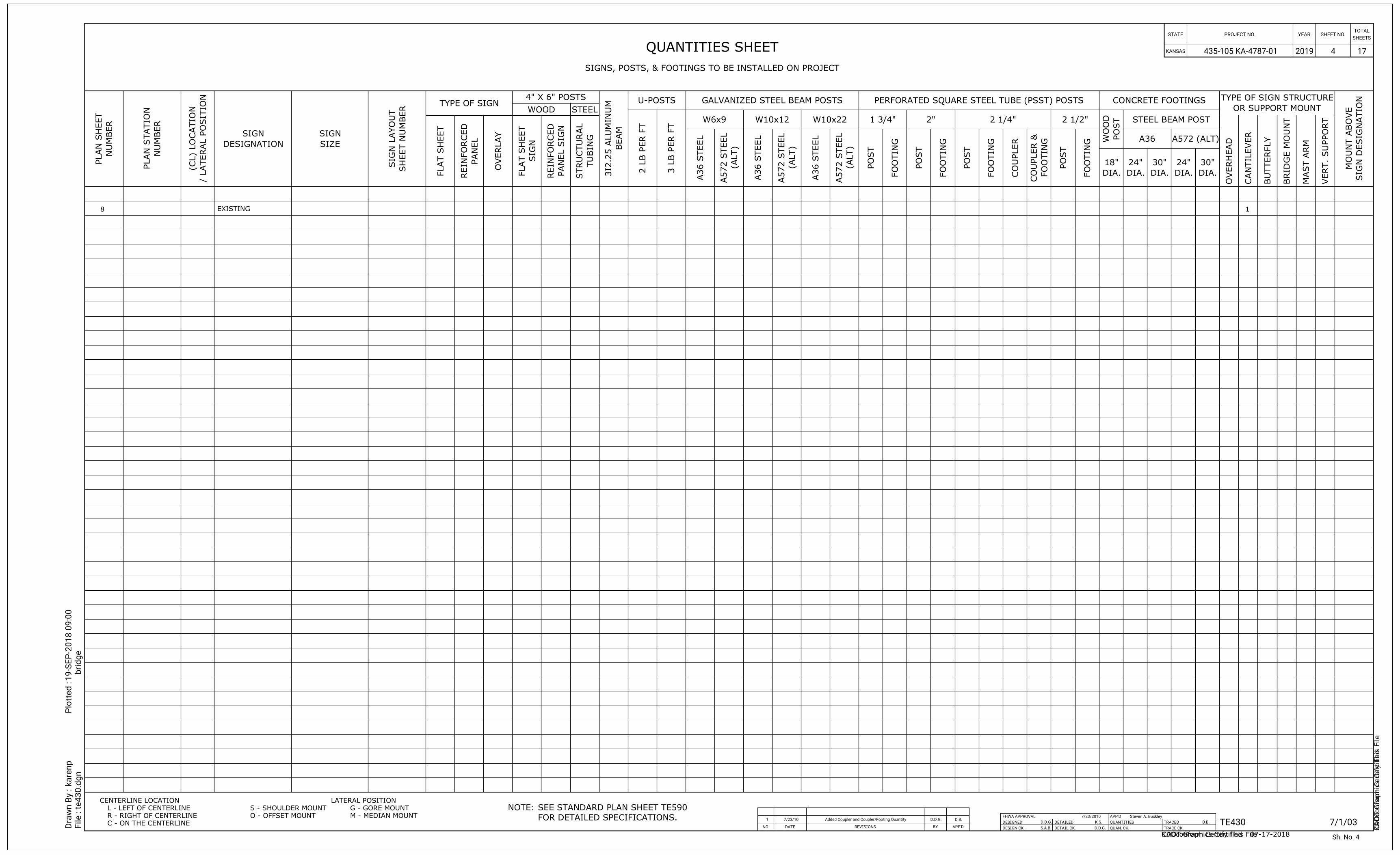
FOR DETAILED SPECIFICATIONS.
SEE STANDARD PLAN SHEET TE590NOTE:CENTERLINE LOCATION LATERAL POSITION
L - LEFT OF CENTERLINE
R - RIGHT OF CENTERLINE
C - ON THE CENTERLINE
S - SHOULDER MOUNT
O - OFFSET MOUNT
G - GORE MOUNT
M - MEDIAN MOUNT
QUANTITIES SHEET
SIGNS, POSTS, & FOOTINGS TO BE INSTALLED ON PROJECT
OV
ER
HE
AD
CA
NTILE
VE
R
BU
TT
ER
FL
Y
BRID
GE M
OU
NT
MA
ST A
RM
VE
RT.
SU
PP
OR
T
FL
AT S
HE
ET
OV
ER
LA
Y
2 L
B P
ER F
T
3 L
B P
ER F
T
A36 S
TE
EL
A36 S
TE
EL
A36 S
TE
EL
PO
ST
FO
OTIN
G
PO
ST
FO
OTIN
G
PO
ST
FO
OTIN
G
PO
ST
FO
OTIN
G
CO
UP
LE
R
4" X 6" POSTSTYPE OF SIGN
WOOD STEEL
U-POSTS GALVANIZED STEEL BEAM POSTS PERFORATED SQUARE STEEL TUBE (PSST) POSTS CONCRETE FOOTINGS
W6x9 W10x12 W10x22 1 3/4" 2" 2 1/4" 2 1/2" STEEL BEAM POST
A36
NU
MB
ER
PL
AN S
HE
ET
NU
MB
ER
PL
AN S
TA
TIO
N
/ L
AT
ER
AL P
OSITIO
N
(C
L) L
OC
ATIO
N
SH
EE
T N
UM
BE
R
SIG
N L
AY
OU
T
DESIGNATION
SIGN
SIZE
SIGN
BE
AM
3I2.2
5 A
LU
MIN
UM
SIG
N D
ESIG
NA
TIO
N
MO
UN
T A
BO
VE
PA
NE
L
REIN
FO
RC
ED
SIG
N
FL
AT S
HE
ET
PA
NE
L SIG
N
REIN
FO
RC
ED
TU
BIN
G
ST
RU
CT
UR
AL
(A
LT)
A572 S
TE
EL
(A
LT)
A572 S
TE
EL
(A
LT)
A572 S
TE
EL
DIA.
18"
DIA.
24"
DIA.
30"
DIA.
24"
DIA.
30"
PO
ST
WO
OD
A572 (ALT)
OR SUPPORT MOUNT
TYPE OF SIGN STRUCTURE
FO
OTIN
G
CO
UP
LE
R &
Sh. No. 4
KD
OT G
raphics C
ertified
KDOT Graphics Certified 07-17-2018
8 1EXISTING
2019435-105 KA-4787-01 174KANSAS
STATE PROJECT NO. YEAR SHEET NO.SHEETS
TOTAL
Dra
wn B
y :
File :
kare
np
Plotted :
te430.d
gn
19-S
EP-2
018 0
9:0
0
bridge
1 7/23/10
D.B.
D.D.G.
REVISIONS BY APP'DDATENO.
Added Coupler and Coupler/Footing Quantity
7/1/03 TE430 D.D.G.
K.S.
S.A.B.
7/23/2010
D.D.G. B.B.
Steven A. Buckley
QUANTITIES
QUAN. CK.
APP'D
TRACED
TRACE CK.
DESIGNED
DESIGN CK.
FHWA APPROVAL
DETAILED
DETAIL CK. CA
Dconform C
ertify T
his File
CADconform Certify This File
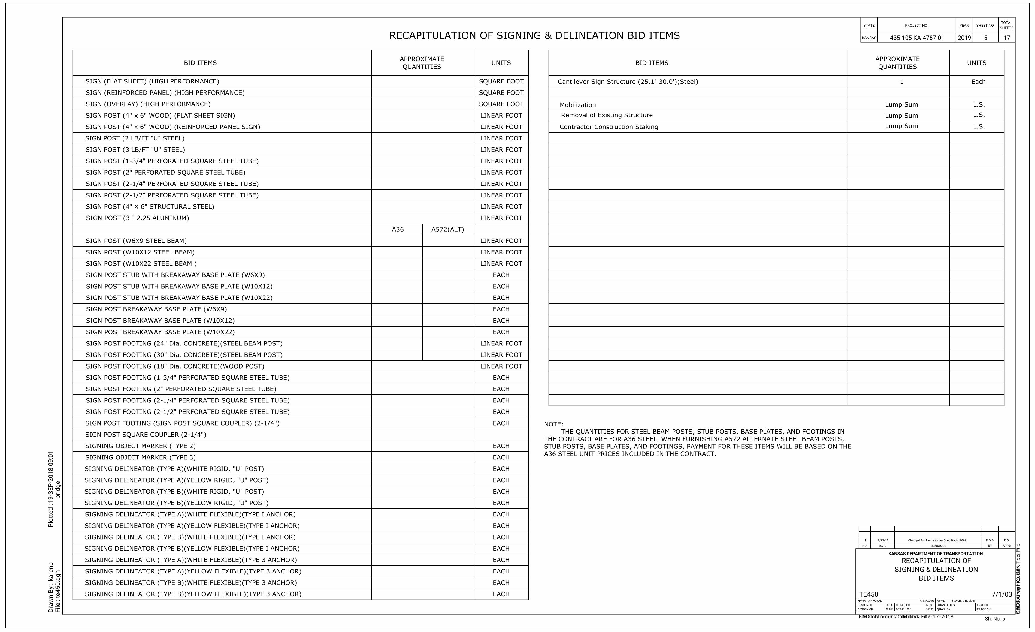
A36 STEEL UNIT PRICES INCLUDED IN THE CONTRACT.
STUB POSTS, BASE PLATES, AND FOOTINGS, PAYMENT FOR THESE ITEMS WILL BE BASED ON THE
THE CONTRACT ARE FOR A36 STEEL. WHEN FURNISHING A572 ALTERNATE STEEL BEAM POSTS,
THE QUANTITIES FOR STEEL BEAM POSTS, STUB POSTS, BASE PLATES, AND FOOTINGS IN
NOTE:
RECAPITULATION OF SIGNING & DELINEATION BID ITEMS
BID ITEMSUNITS
EACH
EACH
EACH
EACH
EACH
EACH
EACH
EACH
EACH
EACH
EACH
EACH
EACH
EACH
EACH
EACH
EACH
EACH
EACH
EACH
BID ITEMS
SIGN (FLAT SHEET) (HIGH PERFORMANCE)
SIGN (REINFORCED PANEL) (HIGH PERFORMANCE)
SIGN (OVERLAY) (HIGH PERFORMANCE)
SIGN POST (4" x 6" WOOD) (FLAT SHEET SIGN)
SIGN POST (4" x 6" WOOD) (REINFORCED PANEL SIGN)
SIGN POST (W6X9 STEEL BEAM)
SIGN POST (W10X12 STEEL BEAM)
SIGN POST (W10X22 STEEL BEAM )
SIGN POST (2 LB/FT "U" STEEL)
SIGN POST (3 LB/FT "U" STEEL)
SIGN POST (1-3/4" PERFORATED SQUARE STEEL TUBE)
SIGN POST (2" PERFORATED SQUARE STEEL TUBE)
SIGN POST (2-1/4" PERFORATED SQUARE STEEL TUBE)
SIGN POST (2-1/2" PERFORATED SQUARE STEEL TUBE)
SIGN POST (4" X 6" STRUCTURAL STEEL)
SIGN POST (3 I 2.25 ALUMINUM)
SIGN POST STUB WITH BREAKAWAY BASE PLATE (W6X9)
SIGN POST STUB WITH BREAKAWAY BASE PLATE (W10X12)
SIGN POST STUB WITH BREAKAWAY BASE PLATE (W10X22)
SIGN POST BREAKAWAY BASE PLATE (W6X9)
SIGN POST BREAKAWAY BASE PLATE (W10X12)
SIGN POST BREAKAWAY BASE PLATE (W10X22)
SIGN POST FOOTING (24" Dia. CONCRETE)(STEEL BEAM POST)
SIGN POST FOOTING (30" Dia. CONCRETE)(STEEL BEAM POST)
SIGN POST FOOTING (18" Dia. CONCRETE)(WOOD POST)
SIGN POST FOOTING (1-3/4" PERFORATED SQUARE STEEL TUBE)
SIGN POST FOOTING (2" PERFORATED SQUARE STEEL TUBE)
SIGN POST FOOTING (2-1/4" PERFORATED SQUARE STEEL TUBE)
SIGN POST FOOTING (2-1/2" PERFORATED SQUARE STEEL TUBE)
SIGNING OBJECT MARKER (TYPE 2)
SIGNING OBJECT MARKER (TYPE 3)
SIGNING DELINEATOR (TYPE A)(WHITE RIGID, "U" POST)
SIGNING DELINEATOR (TYPE A)(YELLOW RIGID, "U" POST)
SIGNING DELINEATOR (TYPE A)(WHITE FLEXIBLE)(TYPE I ANCHOR)
SIGNING DELINEATOR (TYPE A)(YELLOW FLEXIBLE)(TYPE I ANCHOR)
SIGNING DELINEATOR (TYPE A)(WHITE FLEXIBLE)(TYPE 3 ANCHOR)
SIGNING DELINEATOR (TYPE A)(YELLOW FLEXIBLE)(TYPE 3 ANCHOR)
SIGNING DELINEATOR (TYPE B)(WHITE RIGID, "U" POST)
SIGNING DELINEATOR (TYPE B)(YELLOW RIGID, "U" POST)
SIGNING DELINEATOR (TYPE B)(WHITE FLEXIBLE)(TYPE I ANCHOR)
SIGNING DELINEATOR (TYPE B)(YELLOW FLEXIBLE)(TYPE I ANCHOR)
SIGNING DELINEATOR (TYPE B)(WHITE FLEXIBLE)(TYPE 3 ANCHOR)
SIGNING DELINEATOR (TYPE B)(YELLOW FLEXIBLE)(TYPE 3 ANCHOR)
EACH
EACH
EACH
EACH
EACH
SQUARE FOOT
SQUARE FOOT
SQUARE FOOT
LINEAR FOOT
LINEAR FOOT
LINEAR FOOT
LINEAR FOOT
LINEAR FOOT
LINEAR FOOT
LINEAR FOOT
LINEAR FOOT
LINEAR FOOT
LINEAR FOOT
LINEAR FOOT
LINEAR FOOT
LINEAR FOOT
LINEAR FOOT
LINEAR FOOT
LINEAR FOOT
A36 A572(ALT)
QUANTITIES
APPROXIMATE
SIGN POST SQUARE COUPLER (2-1/4")
SIGN POST FOOTING (SIGN POST SQUARE COUPLER) (2-1/4")
QUANTITIES
APPROXIMATEUNITS
Sh. No.
2019
KANSAS DEPARTMENT OF TRANSPORTATION
Dra
wn B
y :
File :
kare
np
Plotted :
te450.d
gn
19-S
EP-2
018 0
9:0
1
bridge
1 7/23/10
D.B.
D.D.G.
REVISIONS BY APP'DDATENO.
TRACED
TRACE CK.
APP'D
QUANTITIES
QUAN. CK.
DETAILED
DETAIL CK.
FHWA APPROVAL
DESIGNED
DESIGN CK.
KANSAS
STATE PROJECT NO. YEARTOTAL
SHEETSSHEET NO.
TE450 7/23/2010
D.D.G.
S.A.B. D.D.G.
K.D.S.
Steven A. Buckley
Changed Bid Items as per Spec Book (2007)
BID ITEMS
SIGNING & DELINEATION
RECAPITULATION OF
7/1/03
435-105 KA-4787-01 5
5
KD
OT G
raphics C
ertified
KDOT Graphics Certified 07-17-2018
1 Each
Mobilization Lump Sum L.S.
17
Removal of Existing Structure Lump Sum L.S.
CA
Dconform C
ertify T
his File
CADconform Certify This File
Cantilever Sign Structure (25.1'-30.0')(Steel)
Contractor Construction Staking Lump Sum L.S.
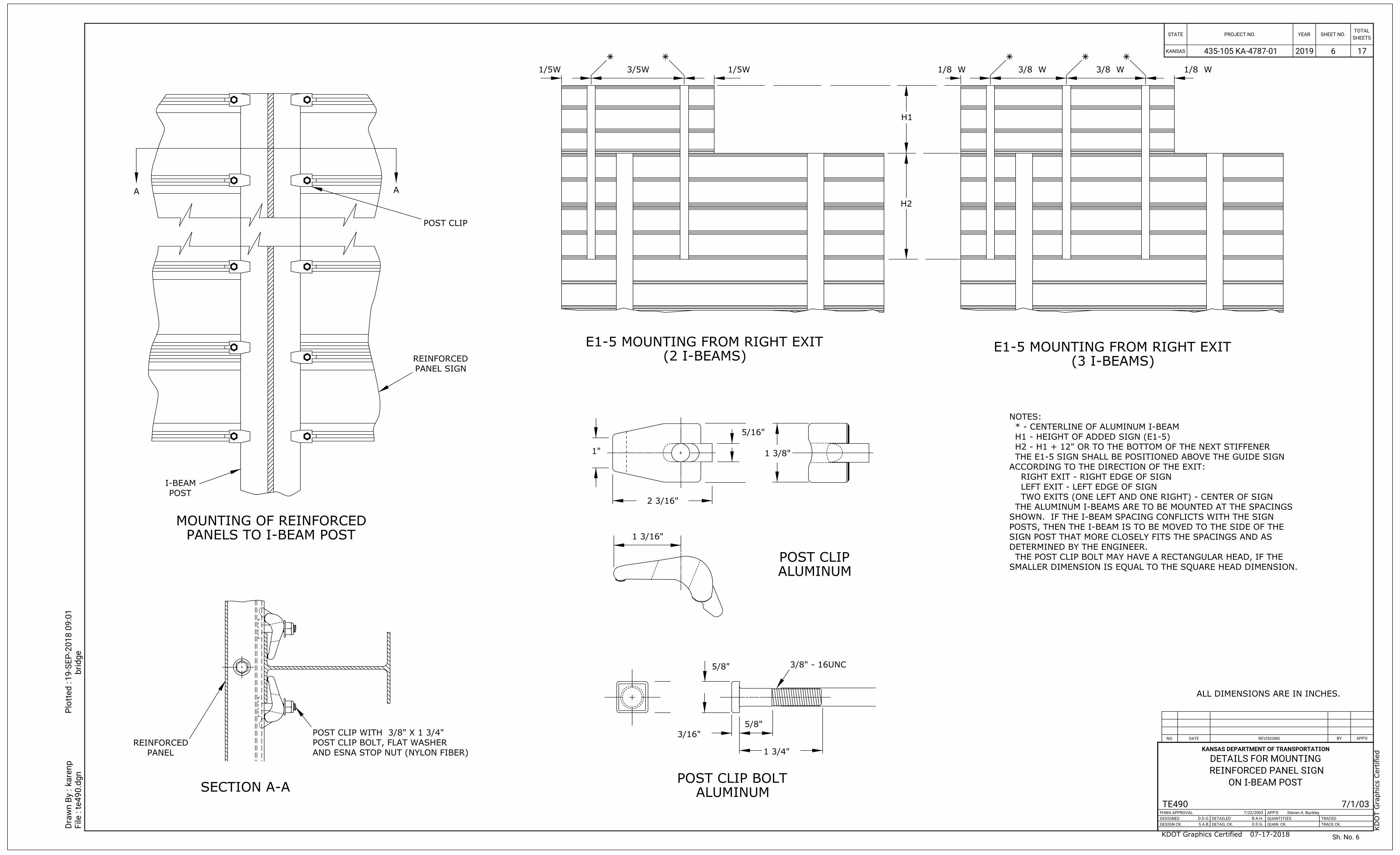
A A
POST CLIP
POST
I-BEAM
PANEL SIGN
REINFORCED
PANELS TO I-BEAM POST
MOUNTING OF REINFORCED
1"
2 3/16"
5/16"
1 3/8"
1 3/16"
3/8" - 16UNC
1 3/4"
3/16"
5/8"
5/8"
ALUMINUM
POST CLIP BOLT
ALUMINUM
POST CLIP
SMALLER DIMENSION IS EQUAL TO THE SQUARE HEAD DIMENSION.
THE POST CLIP BOLT MAY HAVE A RECTANGULAR HEAD, IF THE
DETERMINED BY THE ENGINEER.
SIGN POST THAT MORE CLOSELY FITS THE SPACINGS AND AS
POSTS, THEN THE I-BEAM IS TO BE MOVED TO THE SIDE OF THE
SHOWN. IF THE I-BEAM SPACING CONFLICTS WITH THE SIGN
THE ALUMINUM I-BEAMS ARE TO BE MOUNTED AT THE SPACINGS
TWO EXITS (ONE LEFT AND ONE RIGHT) - CENTER OF SIGN
LEFT EXIT - LEFT EDGE OF SIGN
RIGHT EXIT - RIGHT EDGE OF SIGN
ACCORDING TO THE DIRECTION OF THE EXIT:
THE E1-5 SIGN SHALL BE POSITIONED ABOVE THE GUIDE SIGN
H2 - H1 + 12" OR TO THE BOTTOM OF THE NEXT STIFFENER
H1 - HEIGHT OF ADDED SIGN (E1-5)
* - CENTERLINE OF ALUMINUM I-BEAM
NOTES:
ALL DIMENSIONS ARE IN INCHES.
(2 I-BEAMS)
E1-5 MOUNTING FROM RIGHT EXIT
(3 I-BEAMS)
E1-5 MOUNTING FROM RIGHT EXIT
SECTION A-A
AND ESNA STOP NUT (NYLON FIBER)
POST CLIP BOLT, FLAT WASHER
POST CLIP WITH 3/8" X 1 3/4"
PANEL
REINFORCED
1/5W 3/5W 1/5W
H2
H1
1/8 W 3/8 W 3/8 W 1/8 W
Sh. No.
2019 17
KANSAS DEPARTMENT OF TRANSPORTATION
Dra
wn B
y :
File :
kare
np
Plotted :
te490.d
gn
19-S
EP-2
018 0
9:0
1
bridge
REVISIONS BY APP'DDATENO.
TRACED
TRACE CK.
APP'D
QUANTITIES
QUAN. CK.
DETAILED
DETAIL CK.
FHWA APPROVAL
DESIGNED
DESIGN CK.
KANSAS
STATE PROJECT NO. YEARTOTAL
SHEETSSHEET NO.
TE490 7/22/2003
D.D.G.
S.A.B. D.D.G.
B.A.H.
Steven A. Buckley
ON I-BEAM POST
REINFORCED PANEL SIGN
DETAILS FOR MOUNTING
7/1/03
KD
OT G
raphics C
ertified
KDOT Graphics Certified 07-17-2018
435-105 KA-4787-01 6
6
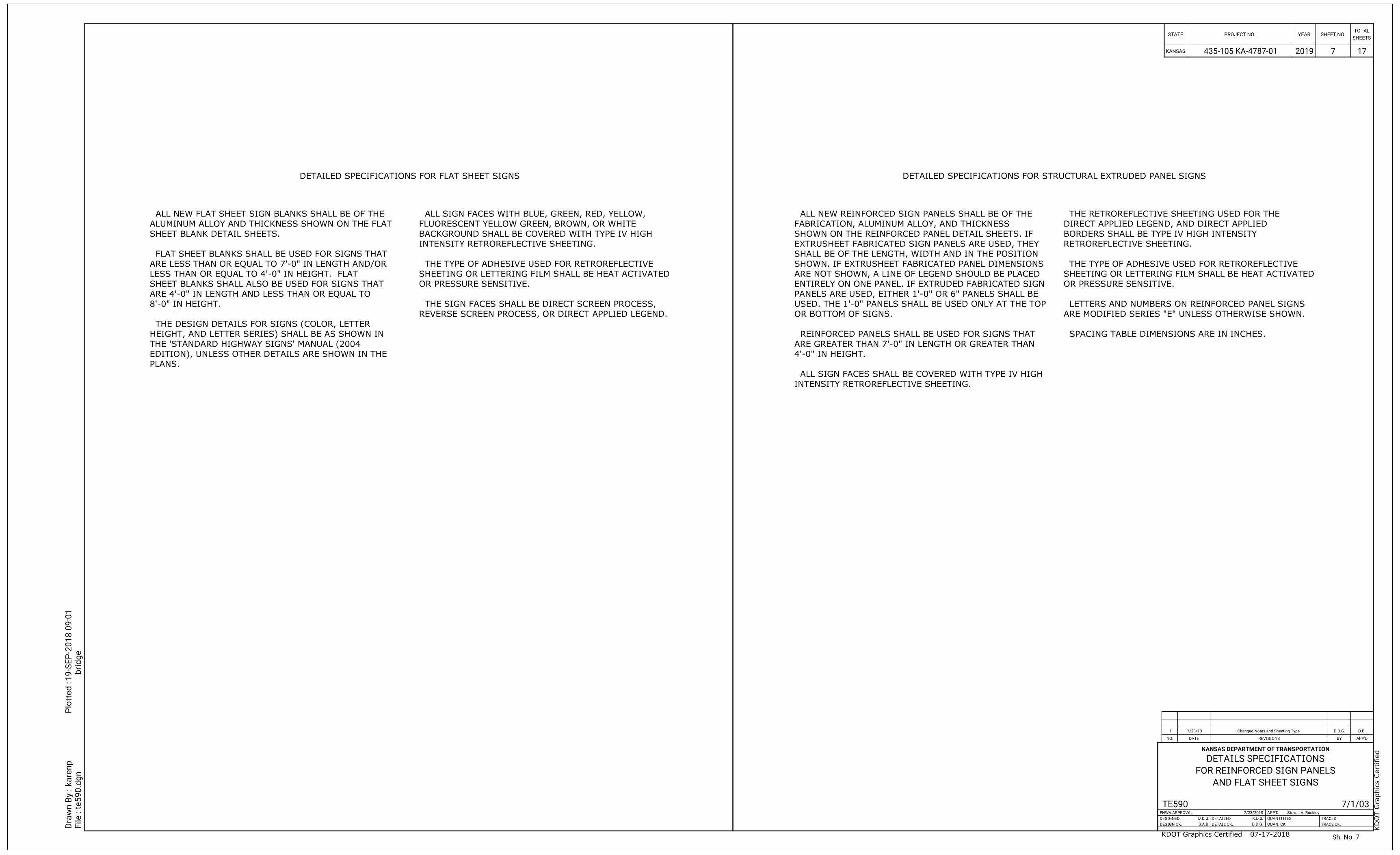
DETAILED SPECIFICATIONS FOR FLAT SHEET SIGNS DETAILED SPECIFICATIONS FOR STRUCTURAL EXTRUDED PANEL SIGNS
PLANS.
EDITION), UNLESS OTHER DETAILS ARE SHOWN IN THE
THE 'STANDARD HIGHWAY SIGNS' MANUAL (2004
HEIGHT, AND LETTER SERIES) SHALL BE AS SHOWN IN
THE DESIGN DETAILS FOR SIGNS (COLOR, LETTER
8'-0" IN HEIGHT.
ARE 4'-0" IN LENGTH AND LESS THAN OR EQUAL TO
SHEET BLANKS SHALL ALSO BE USED FOR SIGNS THAT
LESS THAN OR EQUAL TO 4'-0" IN HEIGHT. FLAT
ARE LESS THAN OR EQUAL TO 7'-0" IN LENGTH AND/OR
FLAT SHEET BLANKS SHALL BE USED FOR SIGNS THAT
SHEET BLANK DETAIL SHEETS.
ALUMINUM ALLOY AND THICKNESS SHOWN ON THE FLAT
ALL NEW FLAT SHEET SIGN BLANKS SHALL BE OF THE
REVERSE SCREEN PROCESS, OR DIRECT APPLIED LEGEND.
THE SIGN FACES SHALL BE DIRECT SCREEN PROCESS,
OR PRESSURE SENSITIVE.
SHEETING OR LETTERING FILM SHALL BE HEAT ACTIVATED
THE TYPE OF ADHESIVE USED FOR RETROREFLECTIVE
INTENSITY RETROREFLECTIVE SHEETING.
BACKGROUND SHALL BE COVERED WITH TYPE IV HIGH
FLUORESCENT YELLOW GREEN, BROWN, OR WHITE
ALL SIGN FACES WITH BLUE, GREEN, RED, YELLOW,
INTENSITY RETROREFLECTIVE SHEETING.
ALL SIGN FACES SHALL BE COVERED WITH TYPE IV HIGH
4'-0" IN HEIGHT.
ARE GREATER THAN 7'-0" IN LENGTH OR GREATER THAN
REINFORCED PANELS SHALL BE USED FOR SIGNS THAT
OR BOTTOM OF SIGNS.
USED. THE 1'-0" PANELS SHALL BE USED ONLY AT THE TOP
PANELS ARE USED, EITHER 1'-0" OR 6" PANELS SHALL BE
ENTIRELY ON ONE PANEL. IF EXTRUDED FABRICATED SIGN
ARE NOT SHOWN, A LINE OF LEGEND SHOULD BE PLACED
SHOWN. IF EXTRUSHEET FABRICATED PANEL DIMENSIONS
SHALL BE OF THE LENGTH, WIDTH AND IN THE POSITION
EXTRUSHEET FABRICATED SIGN PANELS ARE USED, THEY
SHOWN ON THE REINFORCED PANEL DETAIL SHEETS. IF
FABRICATION, ALUMINUM ALLOY, AND THICKNESS
ALL NEW REINFORCED SIGN PANELS SHALL BE OF THE
SPACING TABLE DIMENSIONS ARE IN INCHES.
ARE MODIFIED SERIES "E" UNLESS OTHERWISE SHOWN.
LETTERS AND NUMBERS ON REINFORCED PANEL SIGNS
OR PRESSURE SENSITIVE.
SHEETING OR LETTERING FILM SHALL BE HEAT ACTIVATED
THE TYPE OF ADHESIVE USED FOR RETROREFLECTIVE
RETROREFLECTIVE SHEETING.
BORDERS SHALL BE TYPE IV HIGH INTENSITY
DIRECT APPLIED LEGEND, AND DIRECT APPLIED
THE RETROREFLECTIVE SHEETING USED FOR THE
Sh. No.
2019 17
KANSAS DEPARTMENT OF TRANSPORTATION
Dra
wn B
y :
File :
kare
np
Plotted :
te590.d
gn
19-S
EP-2
018 0
9:0
1
bridge
1 7/23/10
D.B.
D.D.G.
REVISIONS BY APP'DDATENO.
TRACED
TRACE CK.
APP'D
QUANTITIES
QUAN. CK.
DETAILED
DETAIL CK.
FHWA APPROVAL
DESIGNED
DESIGN CK.
KANSAS
STATE PROJECT NO. YEARTOTAL
SHEETSSHEET NO.
TE590 7/23/2010
D.D.G.
S.A.B. D.D.G.
K.D.S.
Steven A. Buckley
Changed Notes and Sheeting Type
AND FLAT SHEET SIGNS
FOR REINFORCED SIGN PANELS
DETAILS SPECIFICATIONS
7/1/03
KD
OT G
raphics C
ertified
KDOT Graphics Certified 07-17-2018
435-105 KA-4787-01 7
7
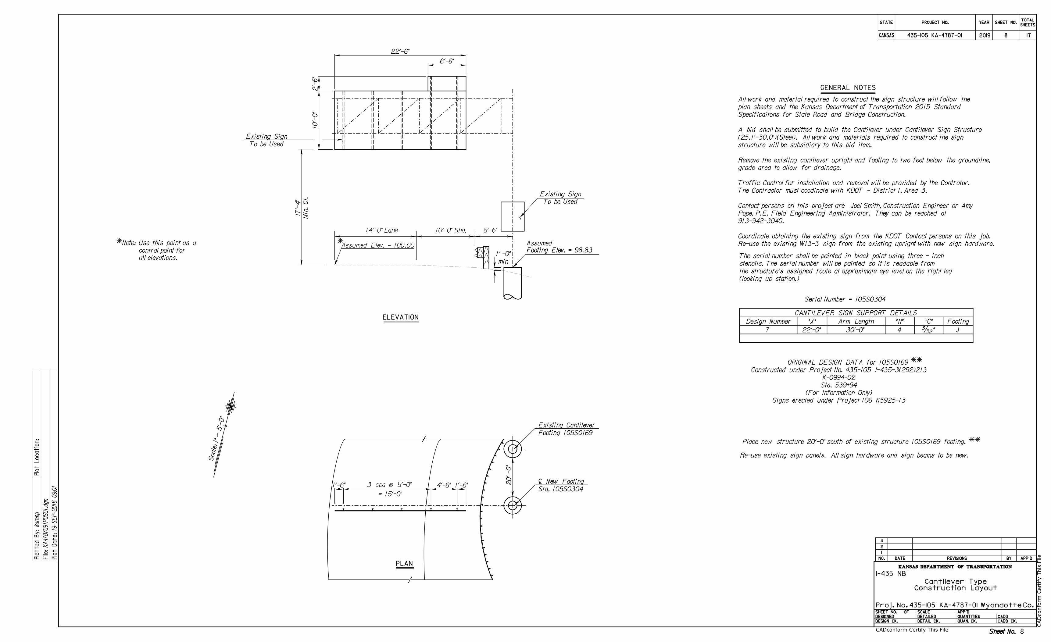
Sheet No.Sheet No.
Co.Proj. No.
2019 8
8
CANTILEVER SIGN SUPPORT DETAILS
Design Number "X" Arm Length "N" "C" Footing
7 22'-0" 30'-0" 4 J‘"
Serial Number = 105S0304Min.
Cl.
17'-
4"
6'-6"
ELEVATION
PLAN
3 spa @ 5'-0"1'-6" 4'-6" 1'-6"
I-435 NB
Construction Layout
Cantilever Type
Wyandotte435-105 KA-4787-01
435-105 KA-4787-01
KANSAS DEPARTMENT OF TRANSPORTATION
DATE REVISIONS BY APP'D
CADD
CADD CK.
SHEET NO.
DESIGNED
DESIGN CK.
SCALE
DETAILED
DETAIL CK.
APP'D
QUANTITIES
QUAN. CK.
OF
3
2
1
NO.
Plotte
d
By:
karenp
Plot
Locatio
n:
KA4787091P
OS01.d
gn
File:
Plot
Date:
19-S
EP-2018 09:0
1
STATE
KANSAS
PROJECT NO. YEAR
TOTAL
SHEETSSHEET NO.
= 15'-0"
6'-6"
22'-6"
10'-
0"
2'-
6"
Scale: 1" = 5'-
0"
(looking up station.)
the structure's assigned route at approximate eye level on the right leg
stencils. The serial number will be painted so it is readable from
The serial number shall be painted in black paint using three - inch all elevations.
control point for
ñNote: Use this point as a Assumed Elev. = 100.00Footing Elev. = Footing Elev. = 98.83
Assumed
GENERAL NOTES
min
1' -0"
20' -0"
14'-0" Lane 10'-0" Sho.
ñ
Footing 105S0169
Existing Cantilever
Sta. 105S0304
{ New Footing
Constructed under Project No. 435-105 I-435-3(292)213
K-0994-02
Sta. 539+94
(For Information Only)
Signs erected under Project 106 K5925-13
Place new structure 20'-0" south of existing structure 105S0169 footing. ññ
Re-use existing sign panels. All sign hardware and sign beams to be new.
17
ORIGINAL DESIGN DATA for 105S0169
Re-use the existing W13-3 sign from the existing upright with new sign hardware.
Coordinate obtaining the existing sign from the KDOT Contact persons on this job.
913-942-3040.
Pope, P.E. Field Engineering Administrator. They can be reached at
Contact persons on this project are Joel Smith, Construction Engineer or Amy
The Contractor must coodinate with KDOT - District 1, Area 3.
Traffic Control for installation and removal will be provided by the Contrator.
grade area to allow for drainage.
Remove the existing cantilever upright and footing to two feet below the groundline,
structure will be subsidiary to this bid item.
(25.1'-30.0')(Steel). All work and materials required to construct the sign
A bid shall be submitted to build the Cantilever under Cantilever Sign Structure
Specificaitons for State Road and Bridge Construction.
plan sheets and the Kansas Department of Transportation 2015 Standard
All work and material required to construct the sign structure will follow the
To be Used
Existing Sign
To be Used
Existing Sign
CA
Dconform C
ertify T
his File
CADconform Certify This File
ññ
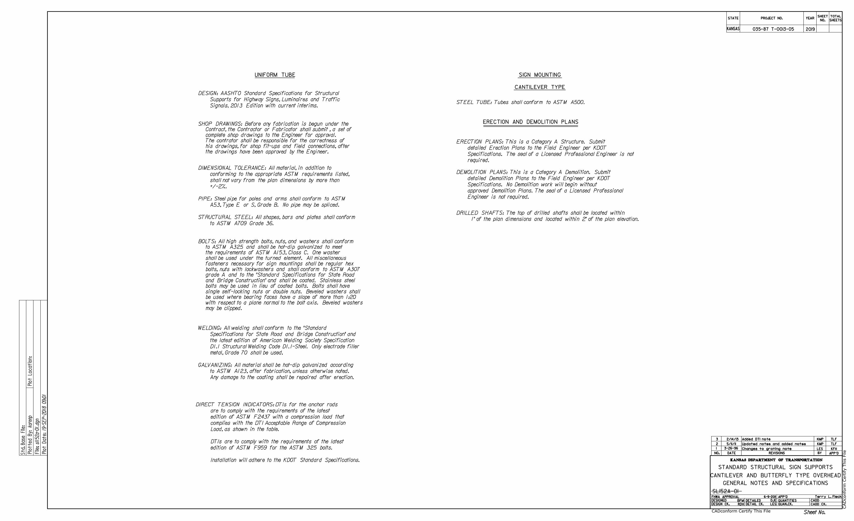
DIMENSIONAL TOLERANCE: All material, in addition to
DESIGN: AASHTO Standard Specifications for Structural
STEEL TUBE: Tubes shall conform to ASTM A500.
STRUCTURAL STEEL: All shapes, bars and plates shall conform
WELDING: All welding shall conform to the "Standard
PIPE: Steel pipe for poles and arms shall conform to ASTM
Supports for Highway Signs, Luminaires and Traffic
to ASTM A709 Grade 36.
+/-2%.
shall not vary from the plan dimensions by more than
conforming to the appropriate ASTM requirements listed,
the latest edition of American Welding Society Specification
Specifications for State Road and Bridge Construction" and
D1.1 Structural Welding Code D1.1-Steel. Only electrode filler
GALVANIZING: All material shall be hot-dip galvanized according
Any damage to the coating shall be repaired after erection.
to ASTM A123, after fabrication, unless otherwise noted.
3-26-96
LES
KFH Changes to grating note
LES
DJE BFM
RDH
STANDARD STRUCTURAL SIGN SUPPORTS
CANTILEVER TYPE
GENERAL NOTES AND SPECIFICATIONS
CANTILEVER AND BUTTERFLY TYPE OVERHEAD
SL152A-01
STATE
KANSAS
PROJECT NO. YEAR
SHEET
NO.
TOTAL
SHEETS
KANSAS DEPARTMENT OF TRANSPORTATION
DATE REVISIONS BY APP'DNO.
DESIGNED
DESIGN CK.
DETAILED
DETAIL CK.
QUANTITIES
QUAN.CK.
APP'DFHWA APPROVAL
CADD
CADD CK.
Std.
Base
File:
sl1
52a-01.d
gn
19-S
EP-2018 09:0
1
karenp
Plotte
d
By:
File:
Plot
Locatio
n:
Plot
Date:
SIGN MOUNTING
ERECTION AND DEMOLITION PLANS
metal, Grade 70 shall be used.
may be clipped.
with respect to a plane normal to the bolt axis. Beveled washers
be used where bearing faces have a slope of more than 1:20
single self-locking nuts or double nuts. Beveled washers shall
bolts may be used in lieu of coated bolts. Bolts shall have
and Bridge Construction" and shall be coated. Stainless steel
grade A and to the "Standard Specifications for State Road
bolts, nuts with lockwashers and shall conform to ASTM A307
fasteners necessary for sign mountings shall be regular hex
shall be used under the turned element. All miscellaneous
the requirements of ASTM A153, Class C. One washer
to ASTM A325 and shall be hot-dip galvanized to meet
BOLTS: All high strength bolts, nuts, and washers shall conform
A53, Type E or S, Grade B. No pipe may be spliced.
Terry L. Fleck
the drawings have been approved by the Engineer.
his drawings, for shop fit-ups and field connections, after
The contrator shall be responsible for the correctness of
complete shop drawings to the Engineer for approval.
Contract, the Contractor or Fabricator shall submit , a set of
SHOP DRAWINGS: Before any fabrication is begun under the
required.
Specifications. The seal of a Licensed Professional Engineer is not
detailed Erection Plans to the Field Engineer per KDOT
ERECTION PLANS: This is a Category A Structure. Submit
Engineer is not required.
approved Demolition Plans. The seal of a Licensed Professional
Specifications. No Demolition work will begin without
detailed Demolition Plans to the Field Engineer per KDOT
DEMOLITION PLANS: This is a Category A Demolition. Submit
1
2 TLFKMP
Signals, 2013 Edition with current interims.
Updated notes and added notes5/11/11
6-9-2011
3 2/14/13 KMP TLFAdded DTI note
Sheet No.
2019
1" of the plan dimensions and located within 2" of the plan elevation.
DRILLED SHAFTS: The top of drilled shafts shall be located within
035-87 T-0013-05
UNIFORM TUBE
CA
Dconform C
ertify T
his File
CADconform Certify This File
Installation will adhere to the KDOT Standard Specifications.
edition of ASTM F959 for the ASTM 325 bolts.
DTIs are to comply with the requirements of the latest
Load, as shown in the table.
complies with the DTI Acceptable Range of Compression
edition of ASTM F2437 with a compression load that
are to comply with the requirements of the latest
DIRECT TENSION INDICATORS: DTIs for the anchor rods
GFK
LES
LES
LRR LRR
LES
LRR
LES
CANTILEVER AND BUTTERFLY TYPE
STANDARD STRUCTURAL SIGN SUPPORTS
OPTIONAL DRILLED SHAFT FOOTING DETAILS
SL152A-03
STATE
KANSAS
PROJECT NO. YEAR
SHEET
NO.
TOTAL
SHEETS
KANSAS DEPARTMENT OF TRANSPORTATION
DATE REVISIONS BY APP'DNO.
DESIGNED
DESIGN CK.
DETAILED
DETAIL CK.
QUANTITIES
QUAN.CK.
APP'DFHWA APPROVAL
CADD
CADD CK.
Std.
Base
File:
sl1
52a-03.d
gn
19-S
EP-2018 09:0
1
karenp
Plotte
d
By:
File:
Brid
ge Desig
nPlot
Locatio
n:
Plot
Date:
Terry L. Fleck
1 5/11/11 KMP TLFUpdated notes and add DTI info
6-9-2011
Added washer to DTI2/06/13 2 KMP TLF
Sheet No.
JPJKMPAdded Note for Foundation9/06/16 3
2019035-87 T-0013-05
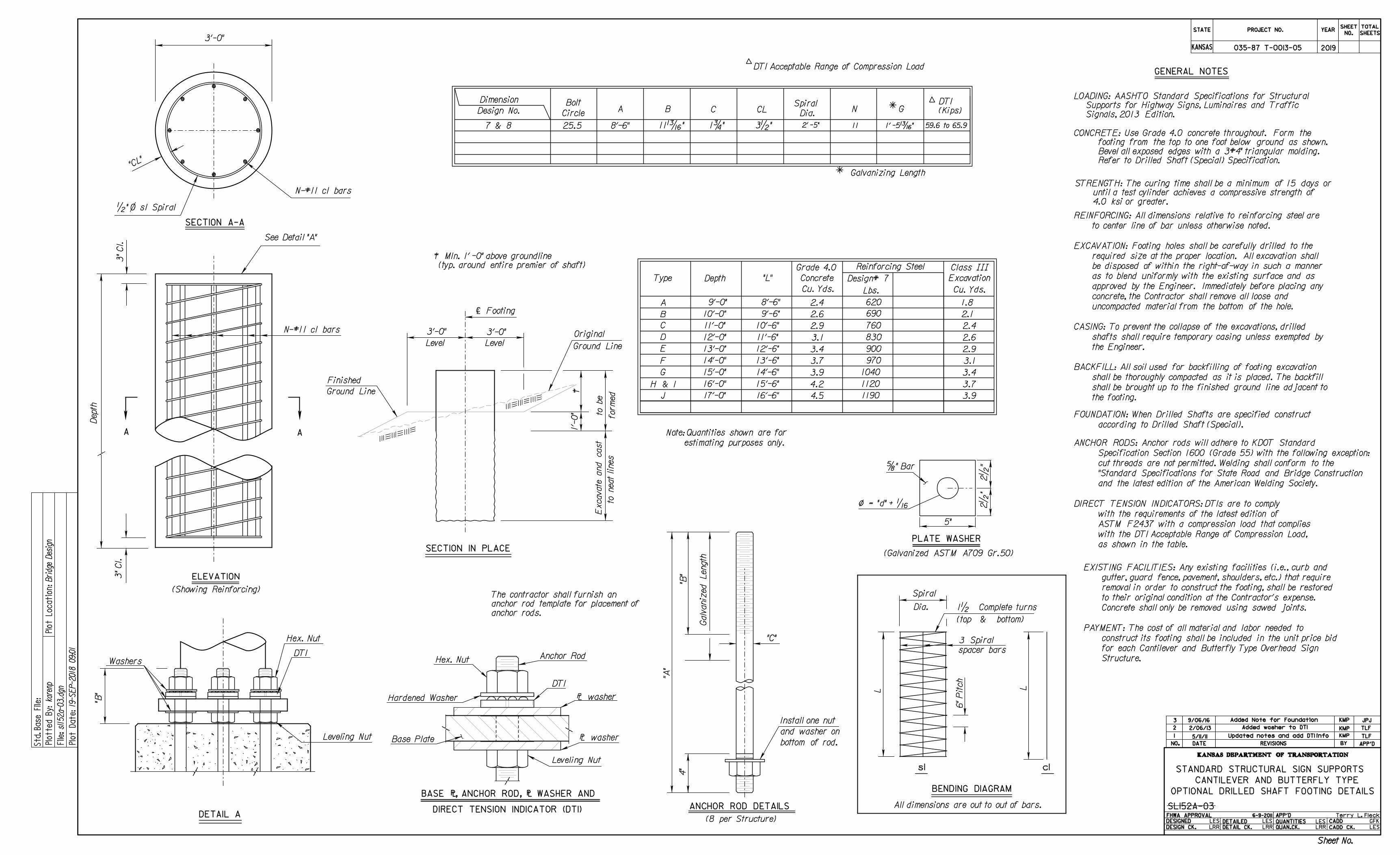
6" Pitch
3 Spiral
spacer bars
EXCAVATION: Footing holes shall be carefully drilled to the
PAYMENT: The cost of all material and labor needed to
EXISTING FACILITIES: Any existing facilities (i.e., curb and
N-#11 c1 bars
See Detail "A"
3'-0"
Depth
3"
Cl.
3"
Cl.
N-#11 c1 bars
•" s1 SpiralO
(Showing Reinforcing)
111111
111
111111
111
1'-
0" to be
for
med
Excavate and cast
to neat lines
{ Footing
3'-0" 3'-0"
Level Level
Original
Ground Line
Type Depth "L" Concrete
Reinforcing Steel Class |||
Excavation
A
B
C
D
E
F
G
H & I
J
9'-0"
10'-0"
11'-0"
12'-0"
13'-0"
14'-0"
15'-0"
16'-0"
17'-0"
8'-6"
9'-6"
10'-6"
11'-6"
12'-6"
13'-6"
14'-6"
15'-6"
16'-6"
Dimension
Design No.Bolt
CircleA B C
Spiral
Dia.N
"CL"
CL
Finished
Ground Line
Cu. Yds.Lbs.Cu. Yds.
1.8
2.1
2.4
2.6
2.9
3.1
3.4
3.7
3.9
620
690
760
830
900
970
1040
1120
1190
2.4
2.6
2.9
3.1
3.4
3.7
3.9
4.2
4.5
"C"
"A"
4"
"B"
REINFORCING: All dimensions relative to reinforcing steel are
to center line of bar unless otherwise noted.
required size at the proper location. All excavation shall
uncompacted material from the bottom of the hole.
be disposed of within the right-of-way in such a manner
approved by the Engineer. Immediately before placing any
concrete, the Contractor shall remove all loose and
BACKFILL: All soil used for backfilling of footing excavation
shall be thoroughly compacted as it is placed. The backfill
shall be brought up to the finished ground line adjacent to
the footing.
construct its footing shall be included in the unit price bid
for each Cantilever and Butterfly Type Overhead Sign
Structure.
gutter, guard fence, pavement, shoulders, etc.) that require
removal in order to construct the footing, shall be restored
to their original condition at the Contractor's expense.
Concrete shall only be removed using sawed joints.
CASING: To prevent the collapse of the excavations, drilled
shafts shall require temporary casing unless exempted by
the Engineer.
as to blend uniformly with the existing surface and as
BENDING DIAGRAM
GENERAL NOTES
SECTION A-A
ELEVATION
SECTION IN PLACE
All dimensions are out to out of bars.
L
L
Spiral
Dia.
(top & bottom)
1• Complete turns
c1s1
A A
Galvaniz
ed Length
Grade 4.0
Gñ
ñ Galvanizing Length
4.0 ksi or greater.
until a test cylinder achieves a compressive strength of
STRENGTH: The curing time shall be a minimum of 15 days or
Leveling Nut
"B"
DETAIL A
WashersDTI
Hex. Nut
according to Drilled Shaft (Special).
FOUNDATION: When Drilled Shafts are specified construct
à
(typ. around entire premier of shaft)
à MIn. 1' -0" above groundline
anchor rods.
anchor rod template for placement of
The contractor shall furnish an
bottom of rod.
and washer on
Install one nut
ANCHOR ROD DETAILS
(8 per Structure)
Signals, 2013 Edition.
Supports for Highway Signs, Luminaires and Traffic
LOADING: AASHTO Standard Specifications for Structural
Refer to Drilled Shaft (Special) Specification.
Bevel all exposed edges with a 3#4" triangular molding.
footing from the top to one foot below ground as shown.
CONCRETE: Use Grade 4.0 concrete throughout. Form the
and the latest edition of the American Welding Society.
"Standard Specifications for State Road and Bridge Construction
cut threads are not permitted. Welding shall conform to the
Specification Section 1600 (Grade 55) with the following exception:
ANCHOR RODS: Anchor rods will adhere to KDOT Standard
8'-6" 1ƒ" 11 59.6 to 65.9
DTI Acceptable Range of Compression Loadí
í
as shown in the table.
with the DTI Acceptable Range of Compression Load,
ASTM F2437 with a compression load that complies
with the requirements of the latest edition of
DIRECT TENSION INDICATORS: DTIs are to comply
estimating purposes only.
Note: Quantities shown are for
5"
PLATE WASHER
†" Bar
2•
"
(Galvanized ASTM A709 Gr.50)
2•
"
ô = "d" + ˆ
DIRECT TENSION INDICATOR (DTI)
Hex. Nut
DTI
Base Plate
Leveling Nut
Hardened Washer
BASE ð, ANCHOR ROD, ð WASHER AND
ð washer
ð washer
Anchor Rod
25.5 11Ž" 3•" 2' -5" 1' -5Ž"
Design# 7
(Kips)
DTI
7 & 8
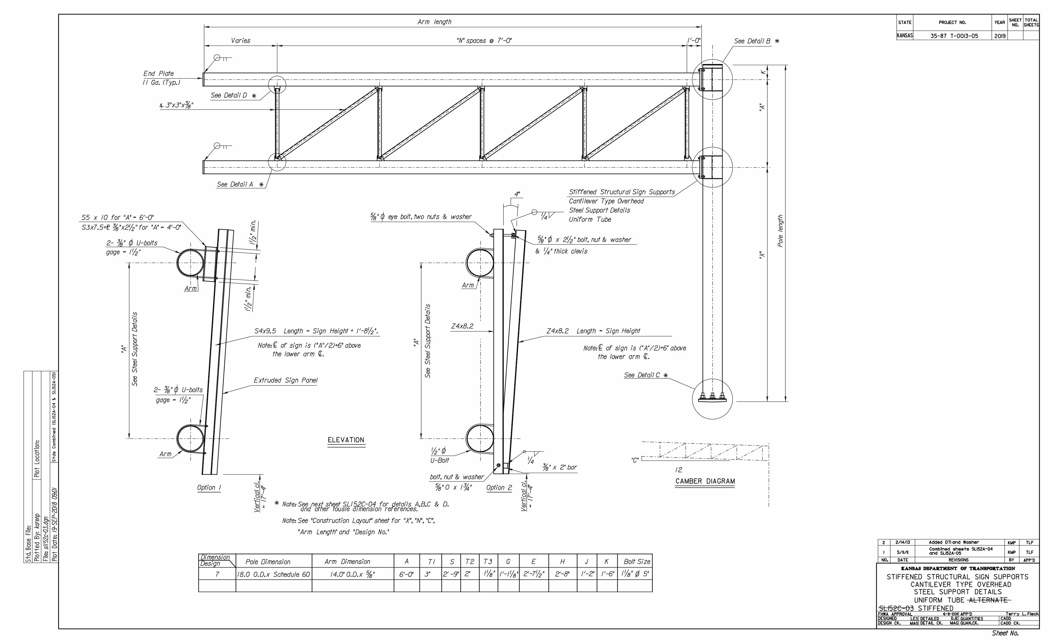
Pole Dimension Arm Dimension A T1DimensionDesign T2 T3 G E H J Bolt Size
Arm length
"N" spaces @ 7'-0" 1'-0"
"A"
"X"
Pole le
ngth
11 Ga. (Typ.)
End Plate
See Detail A
12
"C"
See Detail D
See Detail B
See Detail C
3"x3"x…"�
Varies
MAG
DJE
LES
MAG
CAMBER DIAGRAM
ELEVATION
STIFFENED STRUCTURAL SIGN SUPPORTS
CANTILEVER TYPE OVERHEAD
STEEL SUPPORT DETAILS
UNIFORM TUBE ALTERNATE
Note: See "Construction Layout" sheet for "X", "N", "C",
"Arm Length" and "Design No."
gage = 1•"
Arm
Arm
gage = 1•"
"A"
See Ste
el Support
Details
2- …" O U-bolts
2- …" O U-bolts
C
…"x2•" for "A" = 4'-0"
1•
" min.
1•
" min.
S5 x 10 for "A" = 6'-0"
S3x7.5+�
Option 1
Extruded Sign Panel
Height + 1'-8•".
Note: L of sign is ("A"/2)+6" above
Cthe lower arm L.
S4x9.5 Length = Sign
Arm
"A"
See Ste
el Support
Details
•" O
U-Bolt
…" x 2" bar
Z4x8.2
& ‚" thick clevis
‚
‚
4°
Option 2
Note: L of sign is ("A"/2)+6" aboveC
Cthe lower arm L.
Z4x8.2 Length = Sign Height
†" O x 2•" bolt, nut & washer
†" O eye bolt, two nuts & washer
STATE
KANSAS
PROJECT NO. YEAR
SHEET
NO.
TOTAL
SHEETS
KANSAS DEPARTMENT OF TRANSPORTATION
DATE REVISIONS BY APP'DNO.
DESIGNED
DESIGN CK.
DETAILED
DETAIL CK.
QUANTITIES
QUAN.CK.
APP'DFHWA APPROVAL
CADD
CADD CK.
Std.
Base
File:
sl1
52c-03.d
gn
19-S
EP-2018 09:0
1
karenp
Plotte
d
By:
File:
Plot
Locatio
n:
Plot
Date:
= 17'-
4"
Vertical cl.
= 17'-
4"
Vertical cl.
Terry L. Fleck
Stds
Co
mbin
ed (S
L15
2A-04
&
SL15
2A-05)
1 5/11/11 KMP TLFand SL152A-05
Combined sheets SL152A-04
6-9-2011
Added DTI and Washer TLFKMP2/14/132
Sheet No.
7 6'-0" 2'-8" O1'-2"3" 1„"18.0 O.D.x Schedule 60 1'-1„" 2'-7•"2" 1„" 5"
SL152C-03 STIFFENED
Uniform Tube
Steel Support Details
Cantilever Type Overhead
Stiffened Structural Sign Supports
K
and other tousle dimension references.Note: See next sheet SL152C-04 for details A,B,C & D.
2019
1'-6"
K
14.0" O.D.x †"
35-87 T-0013-05
S
2' -9"
†" O x 1ƒ"
bolt, nut & washer
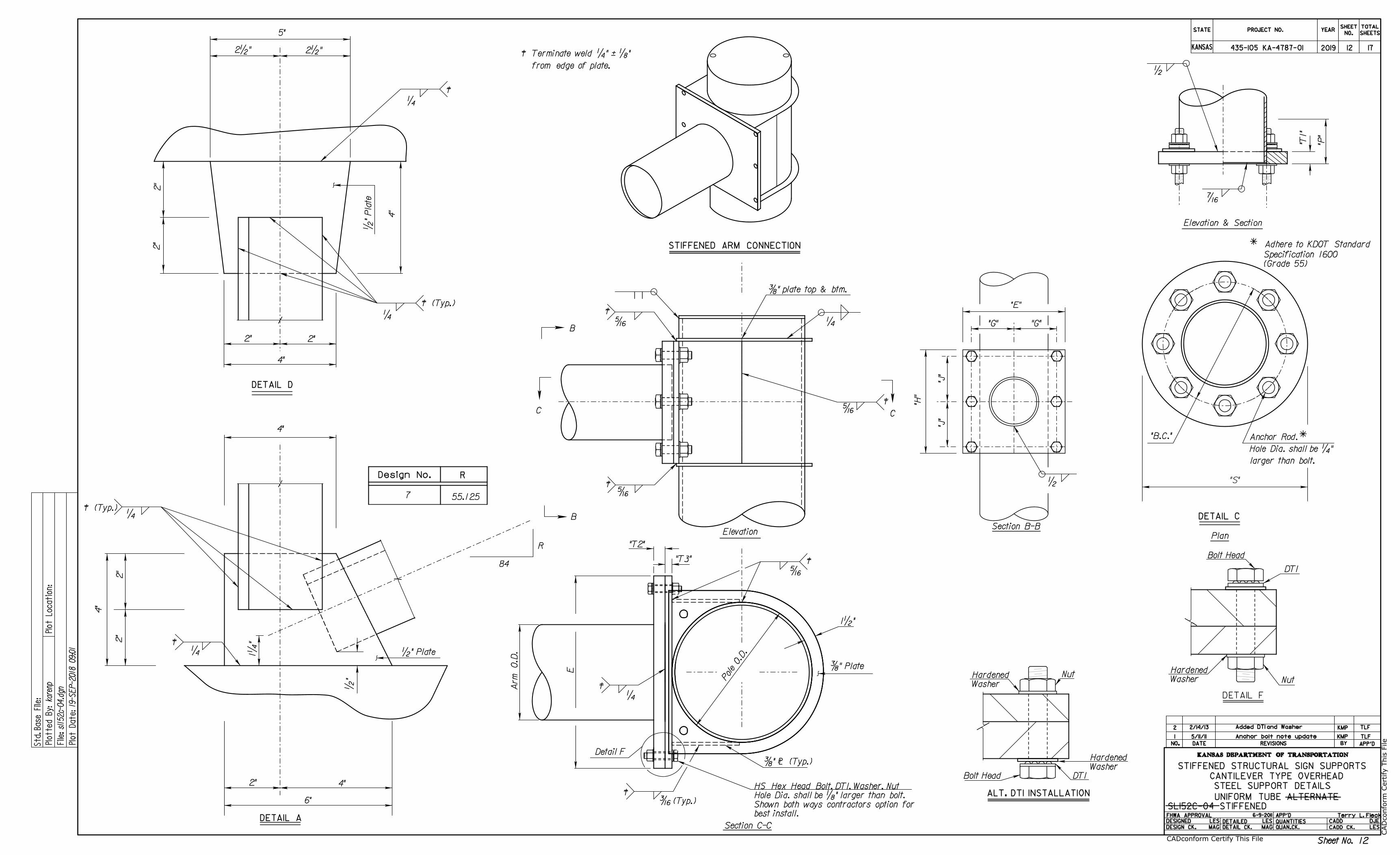
Elevation & Section
"B.C."
larger than bolt.
Hole Dia. shall be ‚"
R
DJE
LES
LES
MAG
LES
MAG
STIFFENED STRUCTURAL SIGN SUPPORTS
CANTILEVER TYPE OVERHEAD
STEEL SUPPORT DETAILS
UNIFORM TUBE ALTERNATE
DETAIL C
DETAIL D
Design No. R
STATE
KANSAS
PROJECT NO. YEARSHEET
NO.
TOTAL
SHEETS
KANSAS DEPARTMENT OF TRANSPORTATION
DATE REVISIONS BY APP'DNO.
DESIGNED
DESIGN CK.
DETAILED
DETAIL CK.
QUANTITIES
QUAN.CK.
APP'DFHWA APPROVAL
CADD
CADD CK.
Std.
Base
File:
sl1
52c-04.d
gn
19-S
EP-2018 09:0
1
karenp
Plotte
d
By:
File:
Plot
Locatio
n:
Plot
Date:
"P"
"T1"
‹
•
Terry L. Fleck
1 5/11/11 KMP TLFAnchor bolt note update
(Grade 55)
Specification 1600
ñ Adhere to KDOT Standard
6-9-2011
Added DTI and Washer TLFKMP2/14/132
Bolt Head
Nut
DTI
DETAIL F
Sheet No.
2019
7 55.125
Section C-C
Elevation
…" plate top & btm.
"T2"
"T3"
Š
Detail F
‚
…" Plate
STIFFENED ARM CONNECTION
B
B
C C
‰ (Typ.)
best install.
Shown both ways contractors option for
Hole Dia. shall be „" larger than bolt.
HS Hex Head Bolt, DTI, Washer, Nut ALT. DTI INSTALLATION
…" � (Typ.)
à
à
à
Bolt Head DTI
Nut
1•"
à
à
à
Washer
Hardened
Washer
Hardened
Pole
O.D.
E
Ar
m
O.D.
from edge of plate.
à Terminate weld ‚" á „"
Plan
Washer
Hardened
Š
Š
Š
‚
SL152C-04 STIFFENED
2"
2"
5"
2•" 2•"
•" Plate
4"
4"
2"2"
‚
à
‚
à (Typ.)
4"2"
6"
•"
1‚
"
DETAIL A
4"
•" Plate
2"
2"
‚
‚
à
84
à (Typ.)
•
"G" "G"
"J"
"H"
"J"
Section B-B
"E"
4"
Anchor Rod.ñ
435-105 KA-4787-01 1712
12
CA
Dconform C
ertify T
his File
CADconform Certify This File
"S"
KANSAS DEPARTMENT OF TRANSPORTATION
Dra
wn B
y :
File :
kare
np
Plotted :
KA478701cpl-01.d
gn
19-S
EP-2
018 0
9:0
1
bridge
APP'D
DETAILED DETAIL CK.DESIGNED DESIGN CK.
KANSAS
STATE PROJECT NO. YEARTOTAL
SHEETSSHEET NO.
Sh. No.
2019
435-105 KA-4787-01
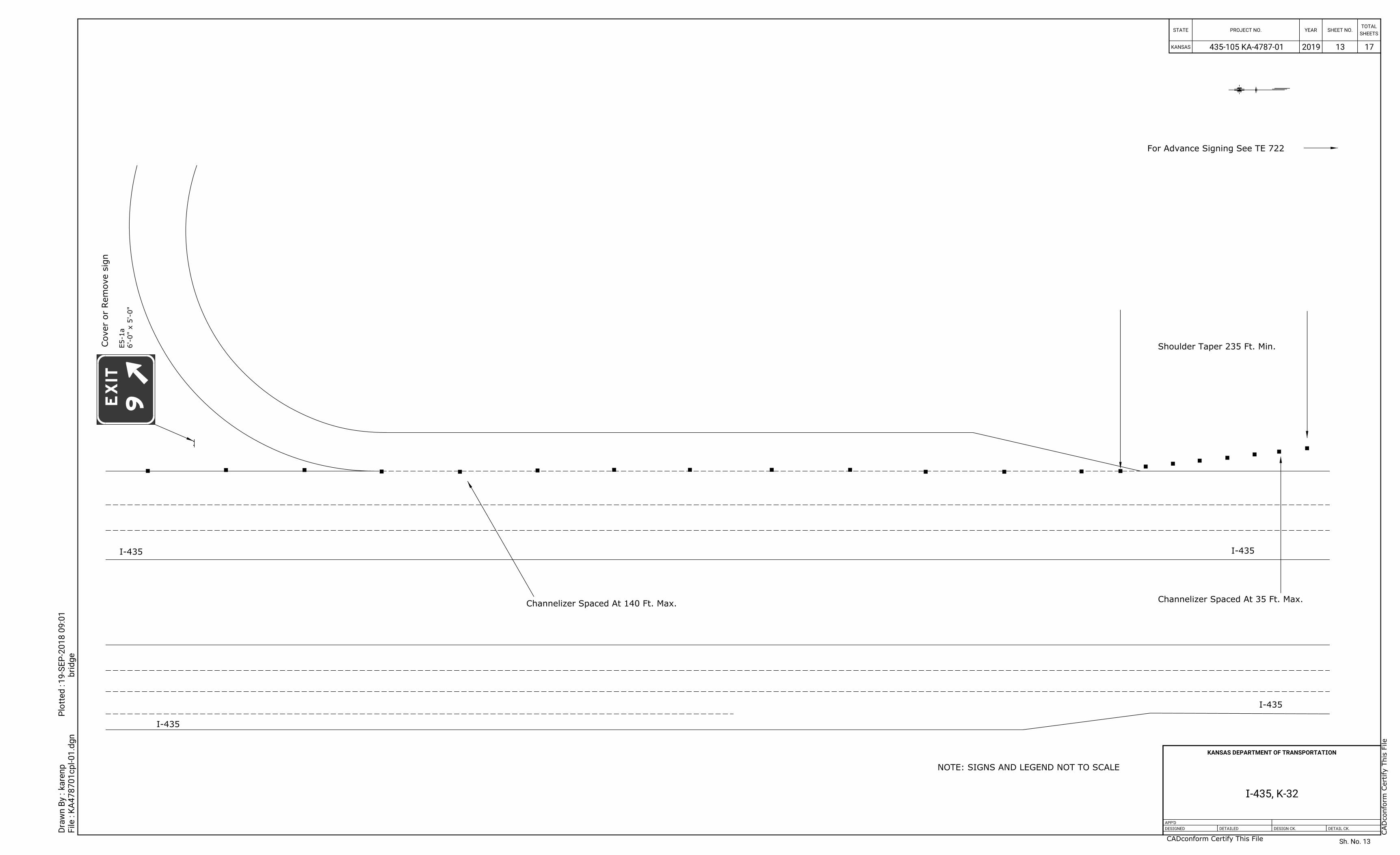
I-435, K-32
17
13
13
CA
Dconform C
ertify T
his File
CADconform Certify This File
Cover or R
em
ove sig
n
I-435 I-435
For Advance Signing See TE 722
Shoulder Taper 235 Ft. Min.
Channelizer Spaced At 140 Ft. Max.
I-435
I-435
NOTE: SIGNS AND LEGEND NOT TO SCALE
EXIT
6'-0" x 5'-0"
E5-1a
9
Channelizer Spaced At 35 Ft. Max.
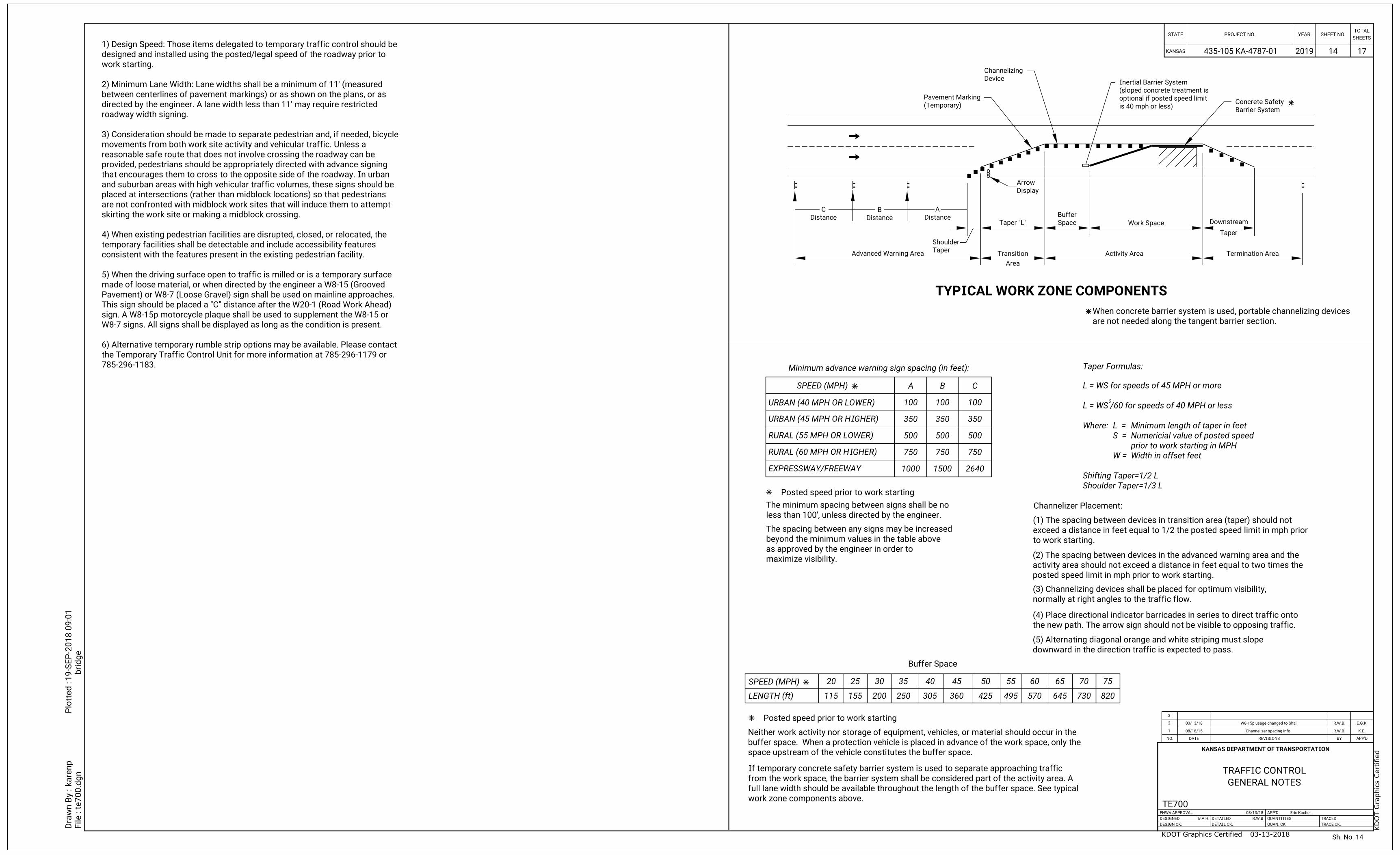
TYPICAL WORK ZONE COMPONENTS
SPEED (MPH)
LENGTH (ft)
20
115
25
155
30
200
35
250
40
305
45
360
50
425 495
55 60
570
65
645
70
730
75
820
Posted speed prior to work starting
URBAN (40 MPH OR LOWER)
URBAN (45 MPH OR HIGHER)
RURAL (55 MPH OR LOWER)
RURAL (60 MPH OR HIGHER)
EXPRESSWAY/FREEWAY 1000
750
500
350
100
A B
100
350
500
750
1500 2640
750
500
350
100
C
less than 100', unless directed by the engineer.
The minimum spacing between signs shall be no
SPEED (MPH)
Posted speed prior to work starting
Channelizer Placement:
normally at right angles to the traffic flow.
(3) Channelizing devices shall be placed for optimum visibility,
posted speed limit in mph prior to work starting.
activity area should not exceed a distance in feet equal to two times the
(2) The spacing between devices in the advanced warning area and the
the new path. The arrow sign should not be visible to opposing traffic.
(4) Place directional indicator barricades in series to direct traffic onto
downward in the direction traffic is expected to pass.
(5) Alternating diagonal orange and white striping must slope
space upstream of the vehicle constitutes the buffer space.
buffer space. When a protection vehicle is placed in advance of the work space, only the
Neither work activity nor storage of equipment, vehicles, or material should occur in the
work zone components above.
full lane width should be available throughout the length of the buffer space. See typical
from the work space, the barrier system shall be considered part of the activity area. A
If temporary concrete safety barrier system is used to separate approaching traffic
are not needed along the tangent barrier section.
When concrete barrier system is used, portable channelizing devices
to work starting.
exceed a distance in feet equal to 1/2 the posted speed limit in mph prior
(1) The spacing between devices in transition area (taper) should not
maximize visibility.
as approved by the engineer in order to
beyond the minimum values in the table above
The spacing between any signs may be increased
Shoulder Taper=1/3 L
Shifting Taper=1/2 L
Width in offset feetW =
prior to work starting in MPH
Numericial value of posted speedS =
Minimum length of taper in feetL =Where:
L = WS /60 for speeds of 40 MPH or less
L = WS for speeds of 45 MPH or more
Advanced Warning Area Transition
Area
Activity Area Termination Area
Device
Channelizing
is 40 mph or less)
optional if posted speed limit
(sloped concrete treatment is
Inertial Barrier System
Barrier System
Concrete Safety
Display
Arrow
Taper
Shoulder
Taper "L" Space
BufferDistance
A
Distance
B
Distance
C
Taper
Work Space Downstream
(Temporary)
Pavement Marking
Buffer Space
Minimum advance warning sign spacing (in feet): Taper Formulas:
*
*
2
Sh. No.
2019 1714
14
785-296-1183.
the Temporary Traffic Control Unit for more information at 785-296-1179 or
6) Alternative temporary rumble strip options may be available. Please contact
W8-7 signs. All signs shall be displayed as long as the condition is present.
sign. A W8-15p motorcycle plaque shall be used to supplement the W8-15 or
This sign should be placed a "C" distance after the W20-1 (Road Work Ahead)
Pavement) or W8-7 (Loose Gravel) sign shall be used on mainline approaches.
made of loose material, or when directed by the engineer a W8-15 (Grooved
5) When the driving surface open to traffic is milled or is a temporary surface
consistent with the features present in the existing pedestrian facility.
temporary facilities shall be detectable and include accessibility features
4) When existing pedestrian facilities are disrupted, closed, or relocated, the
skirting the work site or making a midblock crossing.
are not confronted with midblock work sites that will induce them to attempt
placed at intersections (rather than midblock locations) so that pedestrians
and suburban areas with high vehicular traffic volumes, these signs should be
that encourages them to cross to the opposite side of the roadway. In urban
provided, pedestrians should be appropriately directed with advance signing
reasonable safe route that does not involve crossing the roadway can be
movements from both work site activity and vehicular traffic. Unless a
3) Consideration should be made to separate pedestrian and, if needed, bicycle
roadway width signing.
directed by the engineer. A lane width less than 11' may require restricted
between centerlines of pavement markings) or as shown on the plans, or as
2) Minimum Lane Width: Lane widths shall be a minimum of 11' (measured
work starting.
designed and installed using the posted/legal speed of the roadway prior to
1) Design Speed: Those items delegated to temporary traffic control should be
KANSAS DEPARTMENT OF TRANSPORTATION
Dra
wn B
y :
File :
kare
np
Plotted :
te700.d
gn
19-S
EP-2
018 0
9:0
1
bridge
3
2
1 08/18/15
03/13/18
E.G.K.
K.E.
R.W.B.
R.W.B.
REVISIONS BY APP'DDATENO.
TRACED
TRACE CK.
APP'D
QUANTITIES
QUAN. CK.
DETAILED
DETAIL CK.
FHWA APPROVAL
DESIGNED
DESIGN CK.
KANSAS
STATE PROJECT NO. YEARTOTAL
SHEETSSHEET NO.
TE700 03/13/18
B.A.H.
R.W.B
Eric Kocher
W8-15p usage changed to Shall
Channelizer spacing info
GENERAL NOTES
TRAFFIC CONTROL
KD
OT G
raphics C
ertified
KDOT Graphics Certified 03-13-2018
435-105 KA-4787-01

to the traffic side for channelization.
The stripes shall slope downward
Striping as shown for up to 42".
channelization.
All stripes shall slope downward to the traffic side for
For rails less than 36" long, 4" wide stripes may be used.
the motorist into the intended lane of travel.
The direction indicator barricade shall be used in series to direct
The stripes shall slope downward in the direction traffic is to pass.
Location
Item
Portable
Fixed
No
(1,2)
(1)
(2)
No
Yes
(3) No
(1)
(2)
(3) (3) (3) (3) (3) (3)
(3)(3)(3)
Gores
Devices
Lead-in
(2)(2,3)
Direction Indicator Barricade
Vertical Panels
Conical Delineators
Drums
Type 2 Barricade
Tubular Markers
Vertical Panels
Yes
Yes Yes
Yes
Yes
Yes
Yes
Yes
Yes
Yes
Yes
Yes
Yes
Yes
Yes
Yes
Yes
Yes
Yes
YesYesYes
Cross-o
vers
Diversio
ns
Shoofly
Tangents
Tapers
Ra
mps
Head
Head to
Identifier
Object
Traffic Cones
(2) (2) (2) (2) (2) (2)
No No No
No No
No No No No
NoNo(2) (2) (2)
No No (4) (4) (4) (4) (4) (4)
(4) Daytime operations only.
(3) May be used upon the approval of the engineer.
(2) The stripes shall slope downward to the traffic side for channelization.
(1) Not allowed on centerline delineation along freeways or expressways.
No
6. Use alternating orange/white on interconnected devices.
the alternate path.
having a slope of 12:1 or flatter and having a width equal to
paths with a firm, stable, and slip resistant temporary ramp
5. Treat height differentials > 1/2" in the surfaces of alternate
4. Alternate pathways shall be firm, stable, and slip resistant.
and to provide continuous guidance through or around work.
3. Interconnect pedestrian channelizers to prevent displacement
continuous walls.
2. Hand trailing edges and detection plates are optional for
into the pathway.
1. Support device shall not project beyond the detection plate
Min.
36"Min.
24"
Min.
36"Device
Support
Edge
Hand Trailing
2" Max.
2" Max.
Plate
Detection
Height
8" Min.
38" Max.
32" Min.
Min.
36"
28" Min.
Min.
42"
36"
Approx.
White
KANSAS DEPARTMENT OF TRANSPORTATION
Dra
wn B
y :
File :
kare
np
Plotted :
te702.d
gn
19-S
EP-2
018 0
9:0
1
bridge
3
2
1
REVISIONS BY APP'DDATENO.
TRACED
TRACE CK.
APP'D
QUANTITIES
QUAN. CK.
DETAILED
DETAIL CK.
FHWA APPROVAL
DESIGNED
DESIGN CK.
KANSAS
STATE PROJECT NO. YEARTOTAL
SHEETSSHEET NO.
TE702 06/01/15
L.E.R.
R.W.B.
Kristina Ericksen
CHANNELIZING DEVICES
TRAFFIC CONTROL
VERTICAL PANEL
TUBULAR MARKER
TYPE 2 BARRICADE DIRECTION INDICATOR BARRICADEPEDESTRIAN CHANNELIZER
DRUM TRAFFIC CONE
24" Min.
8" Min.
12" Max.
6"
6"
Orange
White
45°
Orange
White
4"4"
45°
12"
36"
24"
12"
8"
4"
4"45°
Orange
White
6"
2"
4"
3" to 4"
2" Min.
2"
3"
3"
Orange
White
2" to 6"
Orange
White
6" to 8"
6" to 8"
18"
Min. Orange
6" to 8"
6" to 8"
DELINEATOR
CONICAL
Sh. No.
2019 1715
15
KD
OT G
raphics C
ertified
KDOT Graphics Certified 03-29-2018
435-105 KA-4787-01
Shoulder
Shoulder
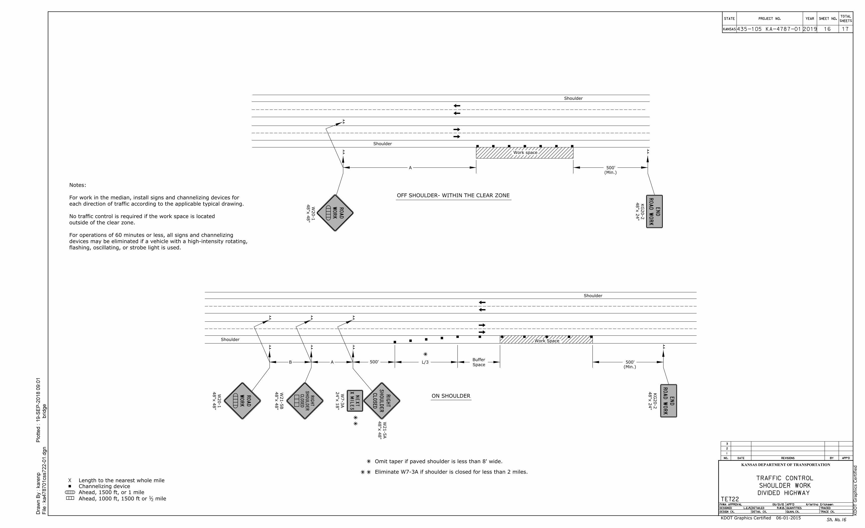
L/3B A 500'
OFF SHOULDER- WITHIN THE CLEAR ZONE
ON SHOULDER
Ahead, 1500 ft, or 1 mile
Omit taper if paved shoulder is less than 8' wide.
48"x 4
8"
W21-5
A
48"x 2
4"
KG
20-2
48"x 2
4"
KG
20-2
24"x 1
8"
W7-3
A
48"x 4
8"
W20-1
48"x 4
8"
W20-1
48"x 4
8"
W21-5
B
Shoulder
Shoulder
Work space
A 500'
500'
Channelizing device
Length to the nearest whole mile
Sh. No.
2019
(Min.)
(Min.)
flashing, oscillating, or strobe light is used.
devices may be eliminated if a vehicle with a high-intensity rotating,
For operations of 60 minutes or less, all signs and channelizing
outside of the clear zone.
No traffic control is required if the work space is located
each direction of traffic according to the applicable typical drawing.
For work in the median, install signs and channelizing devices for
Notes:
Space
Buffer
Work Space
Eliminate W7-3A if shoulder is closed for less than 2 miles.
mile21Ahead, 1000 ft, 1500 ft or
Dra
wn B
y :
File :
kare
np
Plotted :
ka478701css722-0
1.d
gn
19-S
EP-2
018 0
9:0
1
bridge
3
2
1
REVISIONS BY APP'DDATENO.
TRACED
TRACE CK.
APP'D
QUANTITIES
QUAN. CK.
DETAILED
DETAIL CK.
FHWA APPROVAL
DESIGNED
DESIGN CK.
KANSAS
STATE PROJECT NO. YEARTOTAL
SHEETSSHEET NO.
KANSAS DEPARTMENT OF TRANSPORTATION
TE722 06/01/15
L.E.R.
R.W.B.
Kristina Ericksen
DIVIDED HIGHWAY
SHOULDER WORK
TRAFFIC CONTROL
KD
OT G
raphics C
ertified
KDOT Graphics Certified 06-01-2015
435-105 KA-4787-01 1716
16
RIG
HT
SH
OULDER
CLOSED
RO
AD
WO
RK
RO
AD
WO
RK
NE
XT
XMIL
ES
RIG
HT
SH
OULDER
CLOSED
EN
D
RO
AD
WO
RK
EN
D
RO
AD
WO
RK
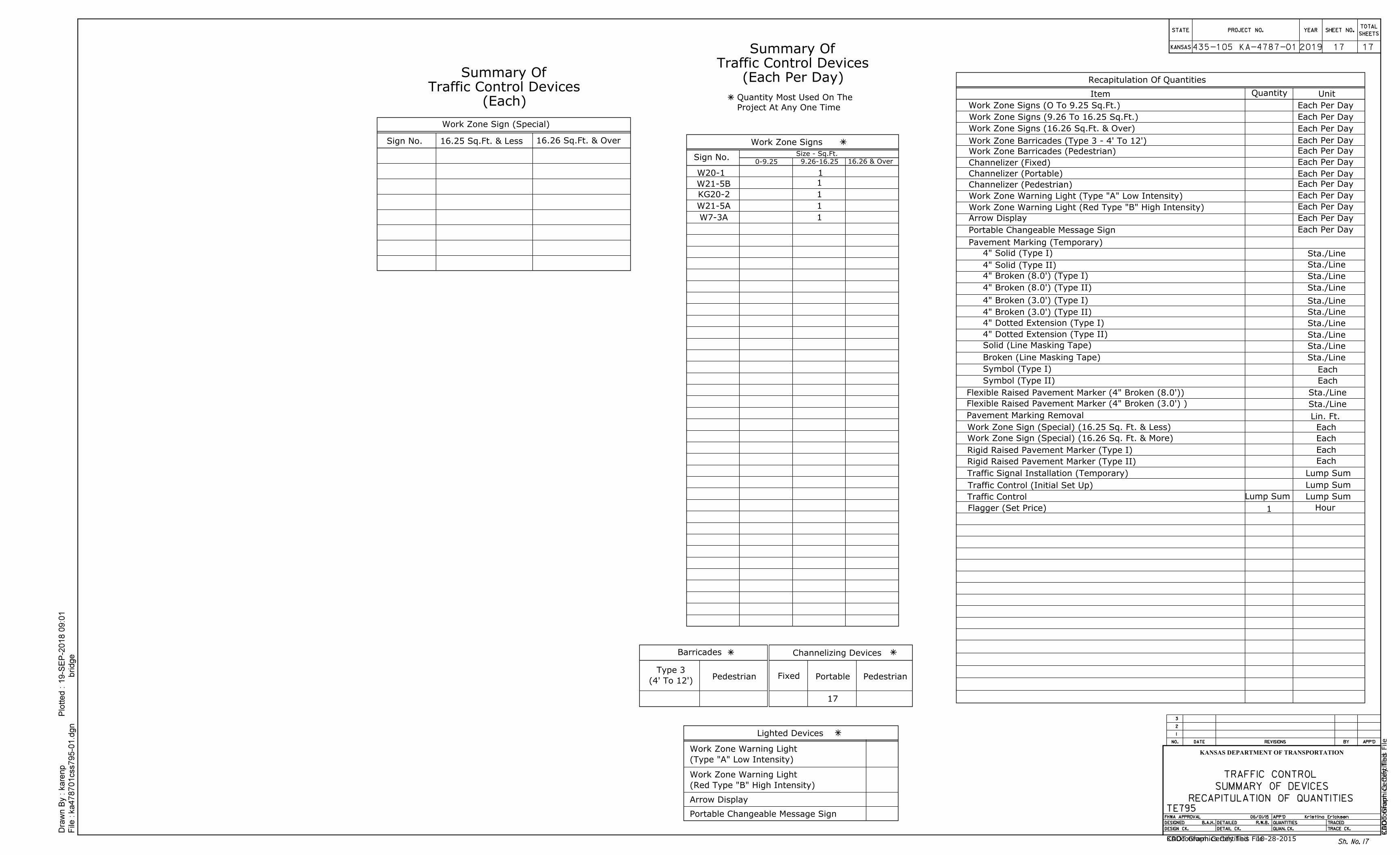
Recapitulation Of Quantities
Work Zone Sign (Special)
Work Zone Signs
Lighted Devices
0-9.25
Sign No. 16.25 Sq.Ft. & Less 16.26 Sq.Ft. & Over
Sign No.9.26-16.25 16.26 & Over
Size - Sq.Ft.
Item Quantity Unit
Work Zone Signs (O To 9.25 Sq.Ft.)
Work Zone Signs (9.26 To 16.25 Sq.Ft.)
Work Zone Signs (16.26 Sq.Ft. & Over)
Channelizer (Fixed)
Channelizer (Portable)
Work Zone Warning Light (Type "A" Low Intensity)
Work Zone Warning Light (Red Type "B" High Intensity)
Arrow Display
Portable Changeable Message Sign
Pavement Marking (Temporary)
Solid (Line Masking Tape)
Broken (Line Masking Tape)
Pavement Marking Removal
Work Zone Sign (Special) (16.25 Sq. Ft. & Less)
Work Zone Sign (Special) (16.26 Sq. Ft. & More)
Traffic Signal Installation (Temporary)
Traffic Control (Initial Set Up)
Traffic Control
Flagger (Set Price) Hour
Lump Sum
Lump Sum
Lump Sum
Each
Each
Each
Each
Lin. Ft.
Sta./Line
Sta./Line
Sta./Line
Sta./Line
Sta./Line
Sta./Line
Sta./Line
Sta./Line
Sta./Line
Sta./Line
Sta./Line
Each Per Day
Each Per Day
Each Per Day
Each Per Day
Each Per Day
Each Per Day
Each Per Day
Each Per Day
Each Per Day
Each Per Day
Arrow Display
Portable Changeable Message Sign
Channelizing Devices
Fixed Portable
Barricades
Sh. No.
2019
Lump Sum
Sta./Line
Flexible Raised Pavement Marker (4" Broken (8.0'))
Work Zone Barricades (Type 3 - 4' To 12')
Symbol (Type I)
Symbol (Type II)
Project At Any One Time
Quantity Most Used On The
(Type "A" Low Intensity)
Work Zone Warning Light
(Red Type "B" High Intensity)
Work Zone Warning Light
(4' To 12')
Type 3
Each
Each
(Each Per Day)
Traffic Control Devices
Summary Of
(Each)
Traffic Control Devices
Summary Of
4" Broken (8.0') (Type I)
4" Broken (8.0') (Type II)
4" Broken (3.0') (Type I)
4" Broken (3.0') (Type II)
4" Dotted Extension (Type I)
4" Dotted Extension (Type II)
4" Solid (Type II)
4" Solid (Type I)
Each Per DayWork Zone Barricades (Pedestrian)
Channelizer (Pedestrian) Each Per Day
Flexible Raised Pavement Marker (4" Broken (3.0') )
PedestrianPedestrian
Dra
wn B
y :
File :
kare
np
Plotted :
ka478701css795-0
1.d
gn
19-S
EP-2
018 0
9:0
1
bridge
3
2
1
REVISIONS BY APP'DDATENO.
TRACED
TRACE CK.
APP'D
QUANTITIES
QUAN. CK.
DETAILED
DETAIL CK.
FHWA APPROVAL
DESIGNED
DESIGN CK.
KANSAS
STATE PROJECT NO. YEARTOTAL
SHEETSSHEET NO.
KANSAS DEPARTMENT OF TRANSPORTATION
TE795 06/01/15
B.A.H.
R.W.B.
Kristina Ericksen
RECAPITULATION OF QUANTITIES
SUMMARY OF DEVICES
TRAFFIC CONTROL
Rigid Raised Pavement Marker (Type I)
Rigid Raised Pavement Marker (Type II)
435-105 KA-4787-01
KD
OT G
raphics C
ertified
KDOT Graphics Certified 10-28-2015
W20-1 1
W21-5B 1
KG20-2 1
W21-5A 1
W7-3A 1
17
17
17
17
CA
Dconform C
ertify T
his File
CADconform Certify This File
1