
CABLE REEL - thelema.co.kr REEL... · This back stop clutch prevents slack cable when this...
25
INSTRUCTION MANUAL DATE : 2001. 6. 15 FILE No. : cmanu05 PAGE : 1 of 25 CABLE REEL TCR - MC TYPE T.H. ELEMA ENG. CO., LTD. TEL : +82-31-498-9270-4 FAX : +82-31-498-9275
Transcript of CABLE REEL - thelema.co.kr REEL... · This back stop clutch prevents slack cable when this...
INSTRUCTION MANUAL
DATE : 2001. 6. 15 FILE No. : cmanu05 PAGE : 1 of 25
CABLE REEL TCR - MC TYPE
T.H. ELEMA ENG. CO., LTD.
TEL : +82-31-498-9270-4 FAX : +82-31-498-9275
CABLE REEL MANUL PAGE : 2 of 25
CONTENTS 1. Introduction and Features 2. Installation of Cable Reel 2.1 Reducer Installation 2.2 Reel Drum Installation 2.3 Guide Roller Installation 2.4 Wiring of Electric Motors 2.5 Reeling Drum Cable Connection and Wiring 2.6 Wining Inside of Slip Ring Housing 2.7 Checking The Position of Limit Switch Cam
3. Operation 3.1 Checking Tension of The Guide Roller 3.2 Checking Over Tension or Slack of Cable
4. Structure and Function 4.1 Magnetic Coupling Unit 4.2 Structure and Function of The Reducer 4.3 Slip Ring Box Structure
5. Adjustment 5.1 Guide Roller Tension Adjustment 5.2 Limit Switch Cam Position Adjustment 5.3 Changing The Rotating Direction of The One Way Clutch 5.4 Magnetic coupling Transmission Torque Adjustment 6. Lubrication 7. Reducer Outline View 8. Sequence Diagram
T.H. ELEMA ENG. CO., LTD. A4(210 × 297mm)
CABLE REEL MANUAL PAGE : 3 of 25
1. INTRODUCTION and FEATURES 1. 1 INTRODUCTION This cable reel is equipped with permanent magnet couplings which can be selected to accommodate for any reeling situation, therefor, ensuring a long life for the cable. No extra devices are required for electric power adjustment or power transmission which makes the cable reel compact and light. 1. 2 Features 1) Because of the compact structure of the cable reel, the area required for installation is minimal, By combined operation with multi-couplings, the tension applied to the cable can be adjusted. Therefore, applying the cable reel to long distance winding or hoisting, the life of the cable becomes longer and the operation is smoother. 2) The magnetic coupling is a non-contact type by applying the strong attractive force of permanent magnets. There is no physical contact or mechanical abrasion and therefore torque adjustment after extensive use is not required. 3) The use of 3-phase induction motors makes maintenance easy as there is no requirement for power adjustment or power transmission devices which could malfunction. Therefore, maintenance is considerably reduced. 4) The transmission torque of the coupling can be adjusted easily, and with the use of planetary reducers, the torque is large and the operation is smooth. 『 Remark』 If a one way clutch is used instead of a brake motor, the direction of the motor rotation must be maintained to prevent damage to the motor and the clutch. An arrow indicating direction of motor rotation is on the fan cover of all motors.
T.H. ELEMA ENG. CO., LTD. A4(210 × 297mm)
CABLE REEL MANUAL PAGE : 4 of 25
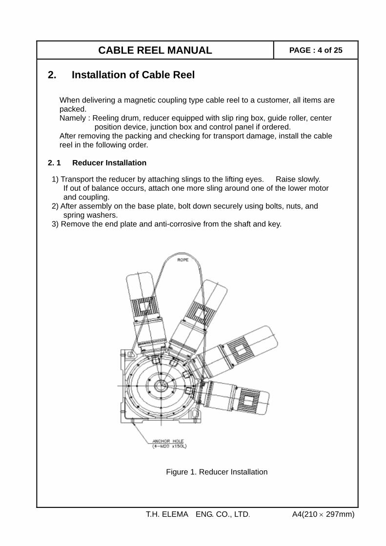
2. Installation of Cable Reel When delivering a magnetic coupling type cable reel to a customer, all items are packed. Namely : Reeling drum, reducer equipped with slip ring box, guide roller, center position device, junction box and control panel if ordered. After removing the packing and checking for transport damage, install the cable reel in the following order. 2. 1 Reducer Installation 1) Transport the reducer by attaching slings to the lifting eyes. Raise slowly. If out of balance occurs, attach one more sling around one of the lower motor and coupling. 2) After assembly on the base plate, bolt down securely using bolts, nuts, and spring washers. 3) Remove the end plate and anti-corrosive from the shaft and key.
T.H. ELEMA ENG. CO., LTD. A4(210 × 297mm)
Figure 1. Reducer Installation
CABLE REEL MANUAL PAGE : 5 of 25
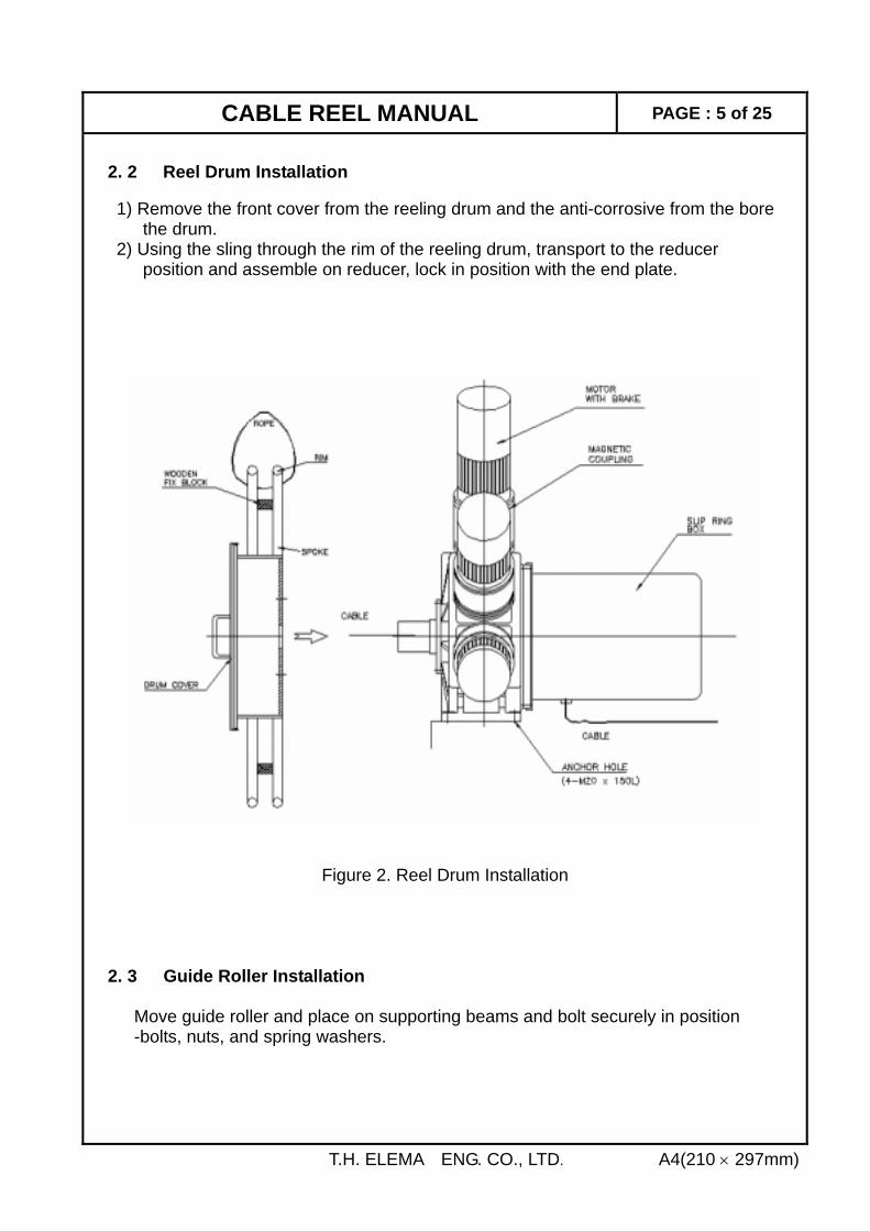
2. 2 Reel Drum Installation 1) Remove the front cover from the reeling drum and the anti-corrosive from the bore the drum. 2) Using the sling through the rim of the reeling drum, transport to the reducer position and assemble on reducer, lock in position with the end plate.
Figure 2. Reel Drum Installation 2. 3 Guide Roller Installation Move guide roller and place on supporting beams and bolt securely in position
-bolts, nuts, and spring washers.
T.H. ELEMA ENG. CO., LTD. A4(210 × 297mm)
CABLE REEL MANUAL PAGE : 6 of 25
2. 4 Wiring of Electric Motors 2. 4. 1 Motors Equipped With Brake 1) Check motor's name plate for voltage, phase and frequency against the supplied voltage. 2) Remove motor terminal cover. 3) Fit the correct size cable gland to terminal box. Fit protective tube over the cable and insert cable through cable gland. Wiring shall be done according to the sequence diagram. Tighten the cable gland and replace terminal box cover. 4) Switch on the power and check that the motors are rotating in the same direction and that the reel is rotating in accordance with the direction of the equipment or hook. If the reel is rotating in the wrong direction, switch off power, change any two phases with each other, and re-check the rotation direction again. 5) Also check whether the operation sequence is in accordance with the reeling drum rotation. 6) If the rotating direction is correct, remove the wooden block from between the spokes. 2. 4. 2 Motors Equipped with Back Stop Clutch This back stop clutch prevents slack cable when this equipment stops or when unwinding against the magnetic coupling. 1) During the assembly of the cable reel, the back stop clutch is positioned correctly for the motor rotation and cable drum winding direction. 2) If the motor is wired incorrectly and rotates in the opposite direction, the one way clutch or the motor may be damaged. So, please use the following method for wiring the motors. a. Take out the cap screws where the housing connects to the planetary gear box and remove motor and housing. b. Remove coupling retaining screw and washer and remove coupling. c. Remove motor fixing screws and remove motor. d. Connect power source to motor terminal and check rotation of motor shaft with the motor rotation arrow marked on the motor fan cover. e. Re-assemble in reverse order. If the motor direction has to be changed due to an error in the specification, the one way clutch has to be reversed. (Refer to section "One Way Clutch Direction Adjustment")
T.H. ELEMA ENG. CO., LTD. A4(210 × 297mm)
CABLE REEL MANUAL PAGE : 7 of 25
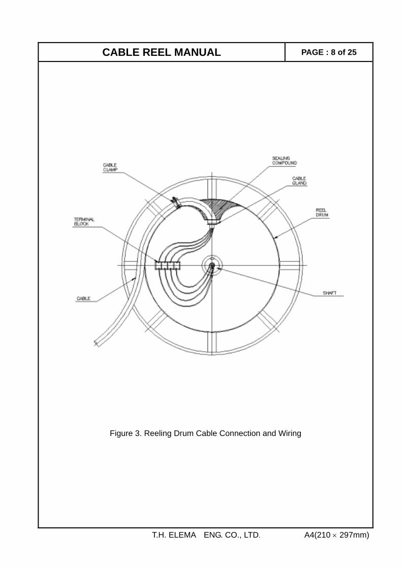
2. 5 Reeling Drum Cable Connection and Wiring Note A. Before cable connection, please read the section "Checking the Position of Limit Switch Cam". B. Check the cable specifications such as section area (mm2), number of cores, outside diameter (mm) and weight per meter length. C. Overall length of cable includes a. Length of cable for inside of drum connection. b. 2 times dead turns on reeling drum. c. Length to ground level through guide rollers. d. Winding length. e. One turn round drum and the length required for junction box connection if using center position device. 1) Take off the drum cover and unscrew the sealing part of the cable gland. 2) Remove cable clamp. 3) Remove outer cover of cable allowing sufficient length for connection to terminal block inside of cable drum (this length can be measured). Fit terminals to the ends of the cables. 4) Feed cable through the guide rollers and through the gland into the reeling drum. 5) Fit sealing part of cable gland over the cables and tighten securely. 6) Where the cable sits on the mating part of cable clamp, wrap rubber strip (thickness 2∼3mm) 2 or 3 times around the cable and then fit and fasten cable clamp securely. 7) Where the cable leads into the drum, seal with compound to keep out moisture. 8) Connect the wires to the terminal block and then fit drum front cover. Taking care that it seals properly.
T.H. ELEMA ENG. CO., LTD. A4(210 × 297mm)
CABLE REEL MANUAL PAGE : 8 of 25
Figure 3. Reeling Drum Cable Connection and Wiring
T.H. ELEMA ENG. CO., LTD. A4(210 × 297mm)
CABLE REEL MANUAL PAGE : 9 of 25
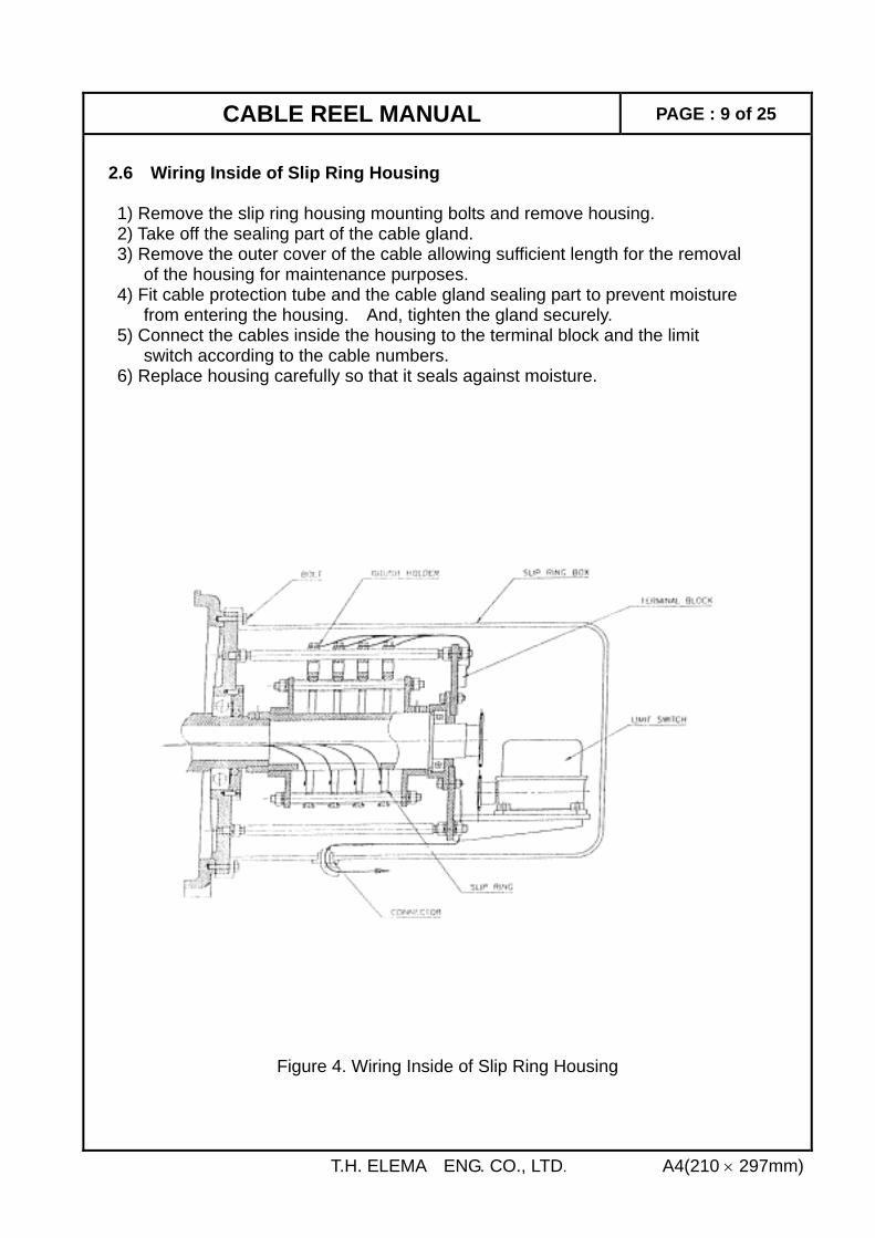
2.6 Wiring Inside of Slip Ring Housing
1) Remove the slip ring housing mounting bolts and remove housing. 2) Take off the sealing part of the cable gland. 3) Remove the outer cover of the cable allowing sufficient length for the removal of the housing for maintenance purposes. 4) Fit cable protection tube and the cable gland sealing part to prevent moisture from entering the housing. And, tighten the gland securely. 5) Connect the cables inside the housing to the terminal block and the limit switch according to the cable numbers. 6) Replace housing carefully so that it seals against moisture.
Figure 4. Wiring Inside of Slip Ring Housing
T.H. ELEMA ENG. CO., LTD. A4(210 × 297mm)
CABLE REEL MANUAL PAGE : 10 of 25
2.7 Checking The Position of Limit Switch Cam A limit switch that detects over travel and torque requirements is fitted to the rear of the slip ring shaft. 1) The limit switch cam angle is changed by the rotation of the worm shaft. The worm shaft is driven by the slip ring shaft by means of a chain and sprocket drive. 2) Take off the limit switch cover and check whether the cam position corresponds to the unwound length of the cable (Refer to drawing on p17 of 25). 3) If the cam position is incorrect, take out the snap ring from the limit switch chain and turn the sprocket until the cam is in the correct position. Replace chain and snap ring. 4) Replace the limit switch cover and then the slip ring cover. Ensure that the slip ring cover seals correctly to prevent moisture entering to the inside of the housing.
T.H. ELEMA ENG. CO., LTD. A4(210 × 297mm)
CABLE REEL MANUAL PAGE : 11 of 25
3. Operation 1) Turn on the power supply, and function the cable reel by using the equipment controls in the crane cabin. 2) Check by jog operation whether the moving direction of the equipment(or moving direction) is in accordance with the rotating direction of the reeling drum. Note : The motor only operate when reeling in the cable. 3) If the rotation direction of the cable reel drum is correct, precede over the full length of travel and check whether over tension in applied to the cable or cable slack occurs. 4) During the above operation, if over tension or cable slack occurs, stop the machine and adjust the tension of the guide rollers and reducer torque to avoid damaging the cable. 5) During operation at intermediate stop points cable slack may occur due to the differences of inertia. At this time, adjust the cable slack control timer to operate the motors for 2∼3 seconds. During the test operation, please check the following items. 3. 1 Check Tension of The Guide Rollers 1) Attached to the guide roller frame are the following limit switches. 2) When winding or un-winding so that over tension does not occur, please adjust the spring force accordingly and check the position of the limit switches and the limit switch actuators. 3) Generally at the time of starting, high tension is applied momentarily. 4) For adjustment of the guide roller tension spring, see page 17 of 26 - 5. 1 guide roller tension adjustment.
T.H. ELEMA ENG. CO., LTD. A4(210 × 297mm)
NO SIGNAL REMARKS
1 HR Cable Over-Tension Detector (Right )
2 HL Cable Over-Tension Detector (Left ) 3 LS1 Cable Direction Detector ( Right ) 4 LS2 Cable Direction Detector (Left )
CABLE REEL MANUAL PAGE : 12 of 25
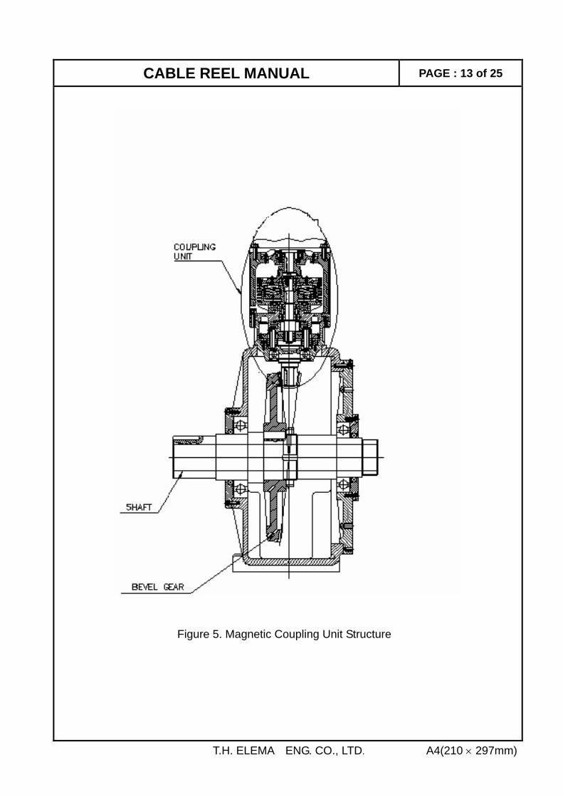
3. 2 Checking Over Tension or Slack of Cable 1) If over tension or slack occurs in the cable, first check that the limit switch cam is in the correct position with regards to the equipment position along its travel length. 2) If the cam is out of position, please adjust according to page 18 of 26 - 5. 2 limit switch cam position adjustment. After adjusting a test run over the complete length of travel should be done. 3) If the cam is in its correct position, the torque can be adjusted by the gap adjustment of the magnetic coupling. 4) First, select the coupling unit that needs to be adjusted by referring to the electric circuit diagram and the coupling test sheet. Please adjust the torque according to page 20 of 26 - 5. 4 magnetic coupling transmission torque adjustment. 4. Structure and Function 4. 1 Magnetic Coupling Unit 1) Torque is transmitted by means of strong magnetic forces re-acting with a disc which is directly connected to the motor shaft. 2) The transmission torque is adjust by varying the air gap between the disc and the permanent magnet segments. For adjustment of the transmission torque see page 20 of 26 - 5. 4 magnetic coupling transmission torque adjustment. 3) The heat that is generated during operation is dissipated by means of cooling fins on the coupling housing and top cover. 4) The motor speed is reduced and the torque is multiplied by the gear box which consists of a planetary reducer and a bevel gear main drive. The planetary gear box was designed with three sets of gears to transmit a high torque and the teeth were heat treated and ground for long life. 5) A bevel gear is fitted to the output shaft of the planetary reducer and transmits the torque to the driving shaft of the cable reel drum.
T.H. ELEMA ENG. CO., LTD. A4(210 × 297mm)
CABLE REEL MANUAL PAGE : 13 of 25
Figure 5. Magnetic Coupling Unit Structure
T.H. ELEMA ENG. CO., LTD. A4(210 × 297mm)
CABLE REEL MANUAL PAGE :14 of 25
4. 2 Structure and Function of The Reducer 1) According to the winding torque required, up to 4 sets of magnetic coupling units can be fitted to the main body of the reducer. 2) For winding in the cable, the motors are running. For un-winding, the motors are stopped. If brake motors are selected for the drive units, the cable is pulled off the reeling drum against the slip of the magnetic coupling as the crane or equipment travels. 3) If motors and back stop clutches are selected, the un-reeling of the cable is prevented by the back stop clutch when the crane or equipment stops. When the crane or equipment is travelling in the direction which pulls off the cable, the cable tension is maintained by slip of the magnetic coupling. 4) When more than 2 sets of the magnetic coupling units are fitted, the units are operated according to the allowable tension of the cable and torque required. During reeling in the cable not all the units are operated. 5) When the allowable tension of the cable is low and in the un-winding direction, the use of a brake motor will increase the working life of a cable by optimizing the cable tension by release of the brake and allowing the coupling to rotate.
T.H. ELEMA ENG. CO., LTD. A4(210 × 297mm)
CABLE REEL MANUAL PAGE : 15 of 25
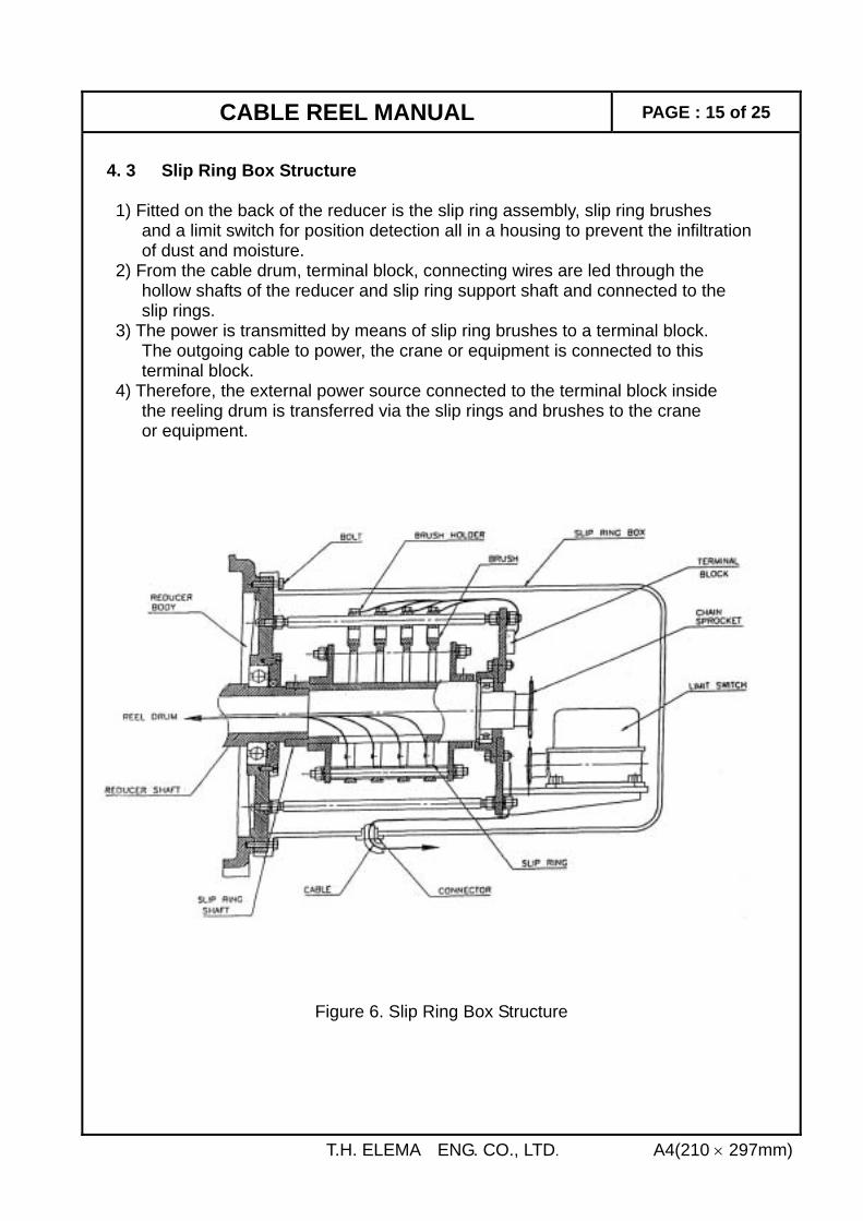
4. 3 Slip Ring Box Structure 1) Fitted on the back of the reducer is the slip ring assembly, slip ring brushes and a limit switch for position detection all in a housing to prevent the infiltration of dust and moisture. 2) From the cable drum, terminal block, connecting wires are led through the hollow shafts of the reducer and slip ring support shaft and connected to the slip rings. 3) The power is transmitted by means of slip ring brushes to a terminal block. The outgoing cable to power, the crane or equipment is connected to this terminal block. 4) Therefore, the external power source connected to the terminal block inside the reeling drum is transferred via the slip rings and brushes to the crane or equipment.
Figure 6. Slip Ring Box Structure
T.H. ELEMA ENG. CO., LTD. A4(210 × 297mm)
CABLE REEL MANUAL PAGE : 16 of 25
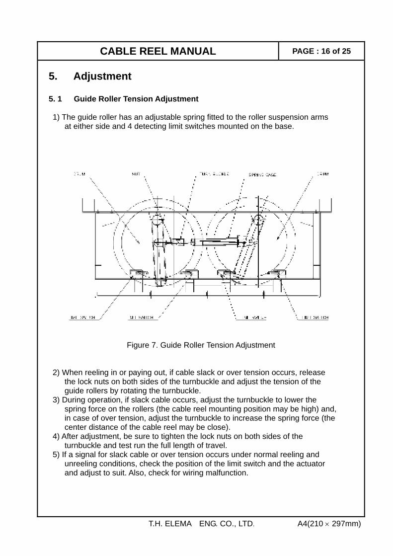
5. Adjustment 5. 1 Guide Roller Tension Adjustment 1) The guide roller has an adjustable spring fitted to the roller suspension arms at either side and 4 detecting limit switches mounted on the base.
Figure 7. Guide Roller Tension Adjustment 2) When reeling in or paying out, if cable slack or over tension occurs, release the lock nuts on both sides of the turnbuckle and adjust the tension of the guide rollers by rotating the turnbuckle. 3) During operation, if slack cable occurs, adjust the turnbuckle to lower the spring force on the rollers (the cable reel mounting position may be high) and, in case of over tension, adjust the turnbuckle to increase the spring force (the center distance of the cable reel may be close). 4) After adjustment, be sure to tighten the lock nuts on both sides of the turnbuckle and test run the full length of travel. 5) If a signal for slack cable or over tension occurs under normal reeling and unreeling conditions, check the position of the limit switch and the actuator and adjust to suit. Also, check for wiring malfunction.
T.H. ELEMA ENG. CO., LTD. A4(210 × 297mm)
CABLE REEL MANUAL PAGE : 17 of 25
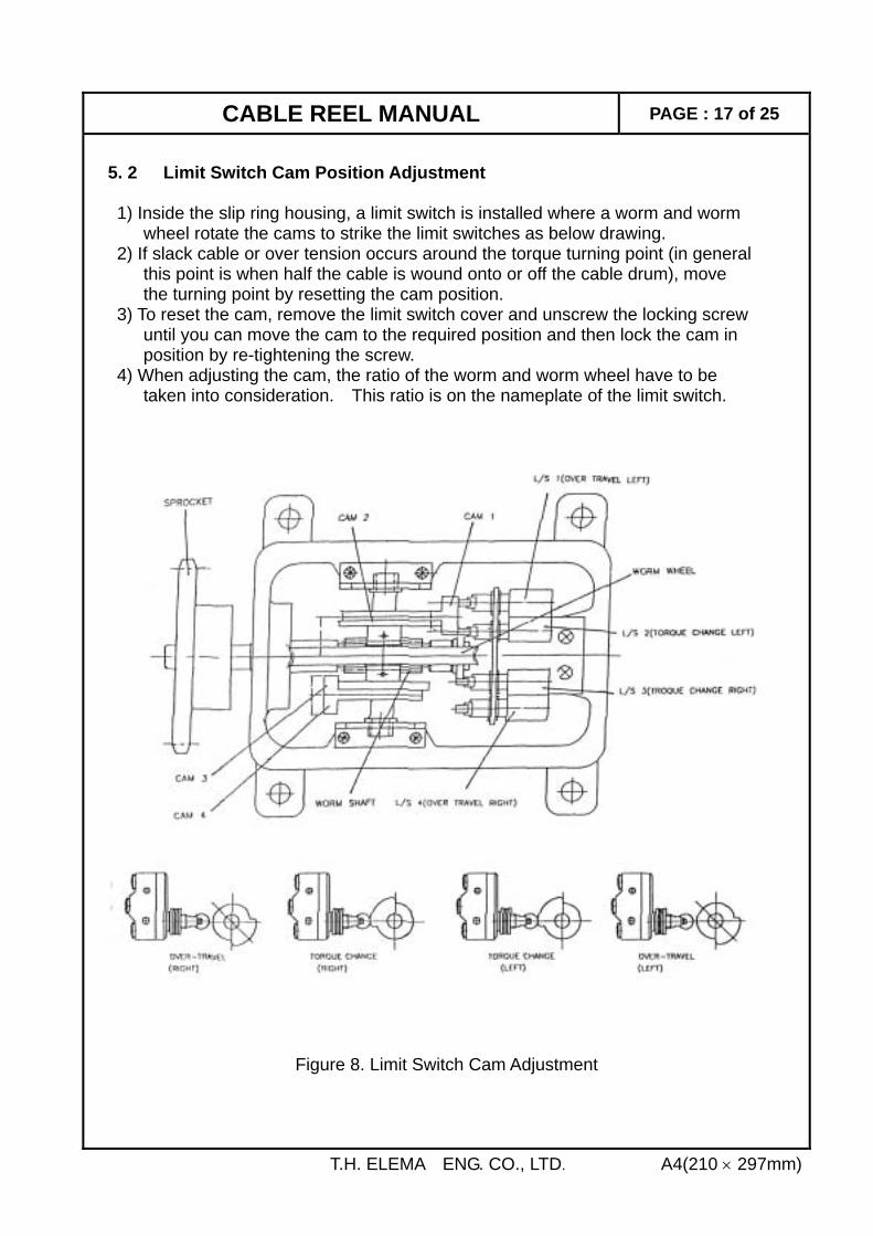
5. 2 Limit Switch Cam Position Adjustment 1) Inside the slip ring housing, a limit switch is installed where a worm and worm wheel rotate the cams to strike the limit switches as below drawing. 2) If slack cable or over tension occurs around the torque turning point (in general this point is when half the cable is wound onto or off the cable drum), move the turning point by resetting the cam position. 3) To reset the cam, remove the limit switch cover and unscrew the locking screw until you can move the cam to the required position and then lock the cam in position by re-tightening the screw. 4) When adjusting the cam, the ratio of the worm and worm wheel have to be taken into consideration. This ratio is on the nameplate of the limit switch.
Figure 8. Limit Switch Cam Adjustment
T.H. ELEMA ENG. CO., LTD. A4(210 × 297mm)
CABLE REEL MANUAL PAGE : 18 of 25
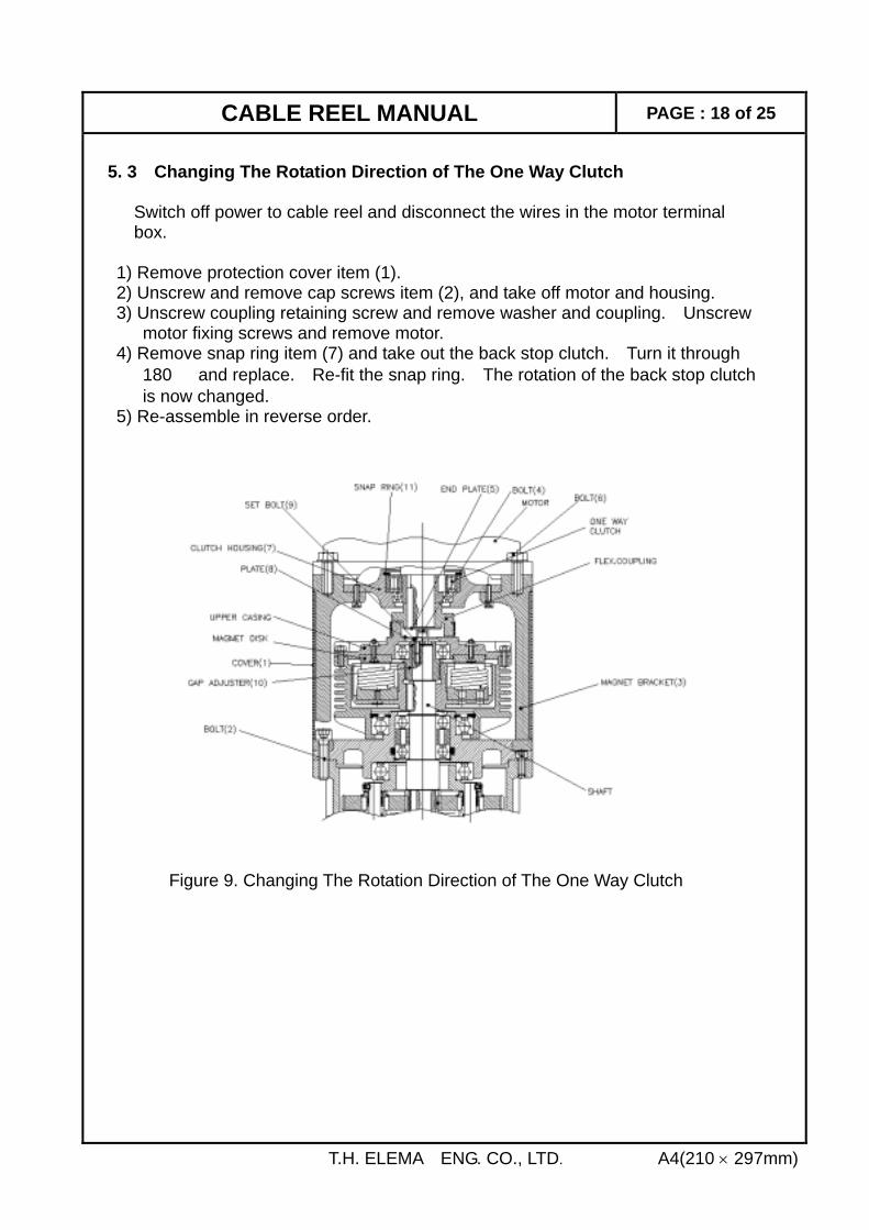
5. 3 Changing The Rotation Direction of The One Way Clutch Switch off power to cable reel and disconnect the wires in the motor terminal box. 1) Remove protection cover item (1). 2) Unscrew and remove cap screws item (2), and take off motor and housing. 3) Unscrew coupling retaining screw and remove washer and coupling. Unscrew motor fixing screws and remove motor. 4) Remove snap ring item (7) and take out the back stop clutch. Turn it through 180。 and replace. Re-fit the snap ring. The rotation of the back stop clutch is now changed. 5) Re-assemble in reverse order. Figure 9. Changing The Rotation Direction of The One Way Clutch
T.H. ELEMA ENG. CO., LTD. A4(210 × 297mm)
CABLE REEL MANUAL PAGE : 19 of 25
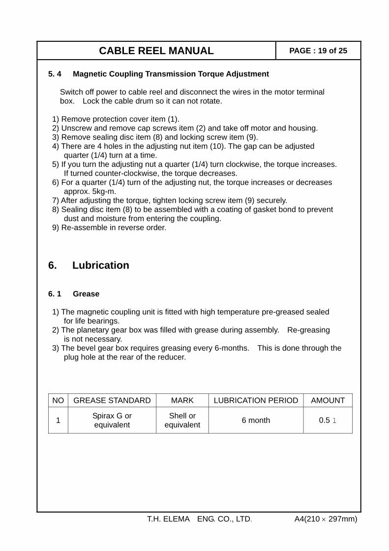
5. 4 Magnetic Coupling Transmission Torque Adjustment Switch off power to cable reel and disconnect the wires in the motor terminal box. Lock the cable drum so it can not rotate. 1) Remove protection cover item (1). 2) Unscrew and remove cap screws item (2) and take off motor and housing. 3) Remove sealing disc item (8) and locking screw item (9). 4) There are 4 holes in the adjusting nut item (10). The gap can be adjusted quarter (1/4) turn at a time. 5) If you turn the adjusting nut a quarter (1/4) turn clockwise, the torque increases. If turned counter-clockwise, the torque decreases. 6) For a quarter (1/4) turn of the adjusting nut, the torque increases or decreases approx. 5kg-m. 7) After adjusting the torque, tighten locking screw item (9) securely. 8) Sealing disc item (8) to be assembled with a coating of gasket bond to prevent dust and moisture from entering the coupling. 9) Re-assemble in reverse order. 6. Lubrication 6. 1 Grease 1) The magnetic coupling unit is fitted with high temperature pre-greased sealed for life bearings. 2) The planetary gear box was filled with grease during assembly. Re-greasing is not necessary. 3) The bevel gear box requires greasing every 6-months. This is done through the plug hole at the rear of the reducer.
T.H. ELEMA ENG. CO., LTD. A4(210 × 297mm)
NO GREASE STANDARD MARK LUBRICATION PERIOD AMOUNT
1 Spirax G or equivalent
Shell or equivalent 6 month 0.5 l
CABLE REEL MANUAL PAGE : 20 of 25
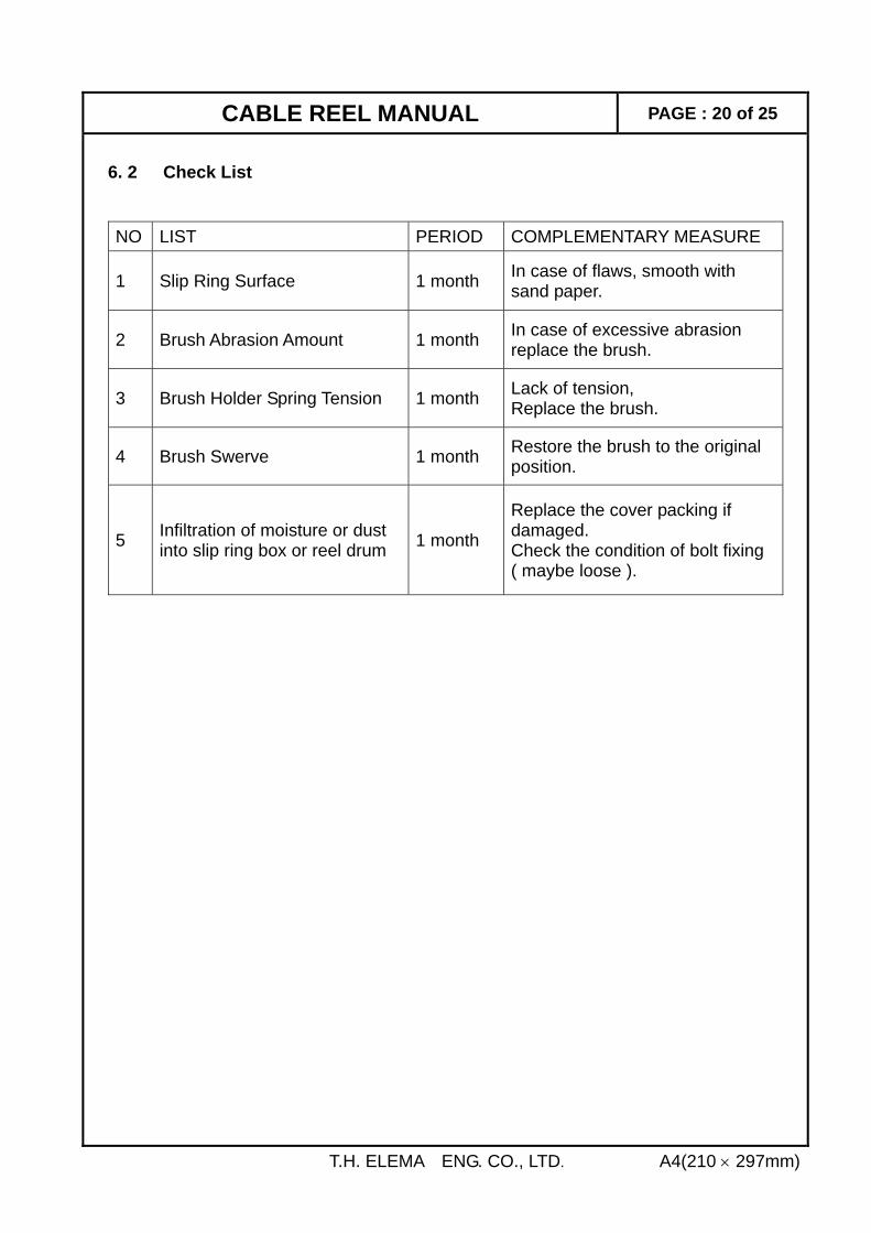
6. 2 Check List
T.H. ELEMA ENG. CO., LTD. A4(210 × 297mm)
NO LIST PERIOD COMPLEMENTARY MEASURE
1 Slip Ring Surface 1 month In case of flaws, smooth with sand paper.
2 Brush Abrasion Amount 1 month In case of excessive abrasion replace the brush.
3 Brush Holder Spring Tension 1 month Lack of tension, Replace the brush.
4 Brush Swerve 1 month Restore the brush to the original position.
5 Infiltration of moisture or dust into slip ring box or reel drum 1 month
Replace the cover packing if damaged. Check the condition of bolt fixing ( maybe loose ).
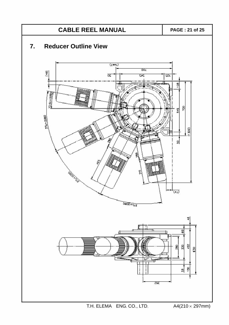
CABLE REEL MANUAL PAGE : 21 of 25
7. Reducer Outline View
T.H. ELEMA ENG. CO., LTD. A4(210 × 297mm)
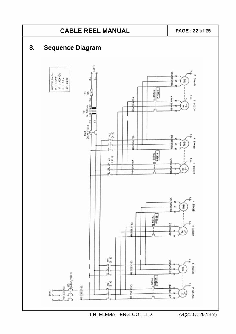
CABLE REEL MANUAL PAGE : 22 of 25
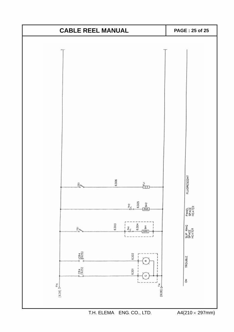
8. Sequence Diagram
T.H. ELEMA ENG. CO., LTD. A4(210 × 297mm)
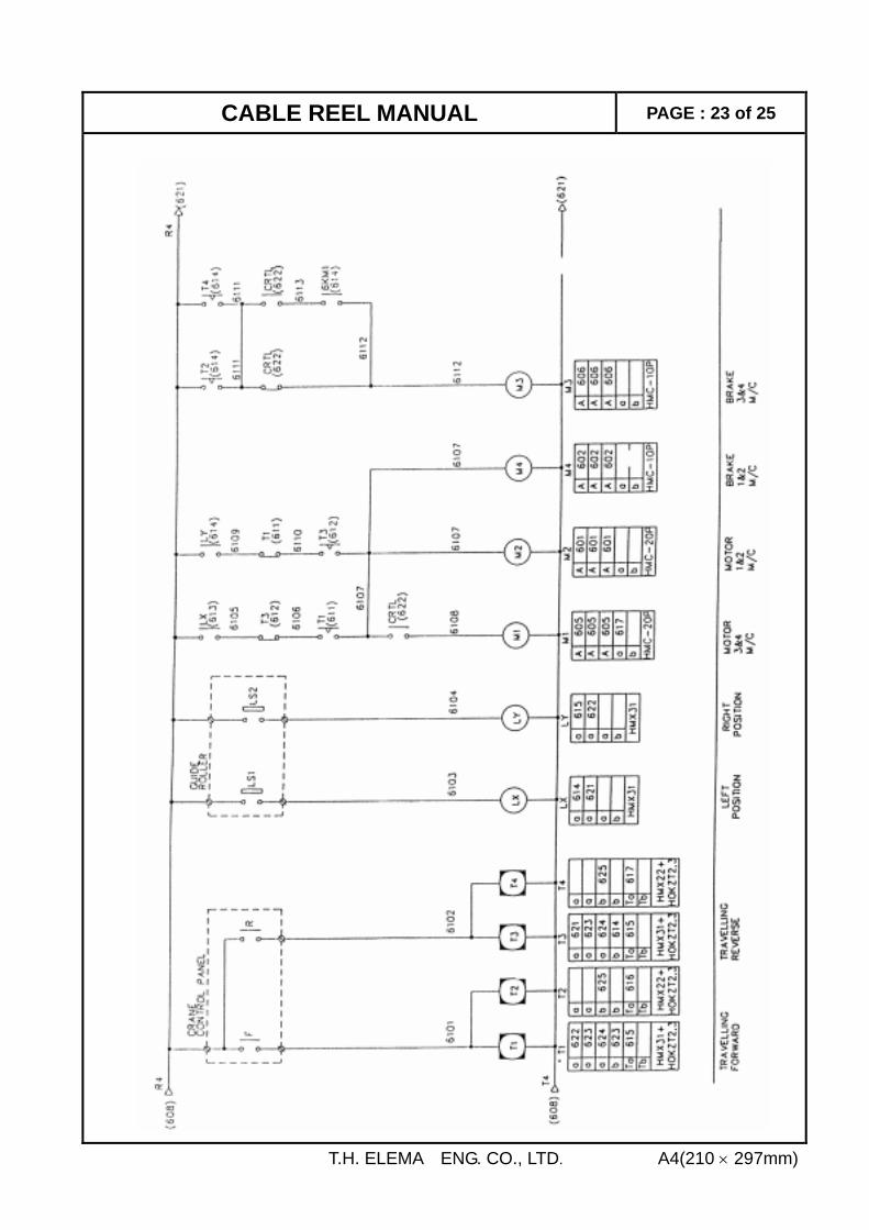
CABLE REEL MANUAL PAGE : 23 of 25
T.H. ELEMA ENG. CO., LTD. A4(210 × 297mm)
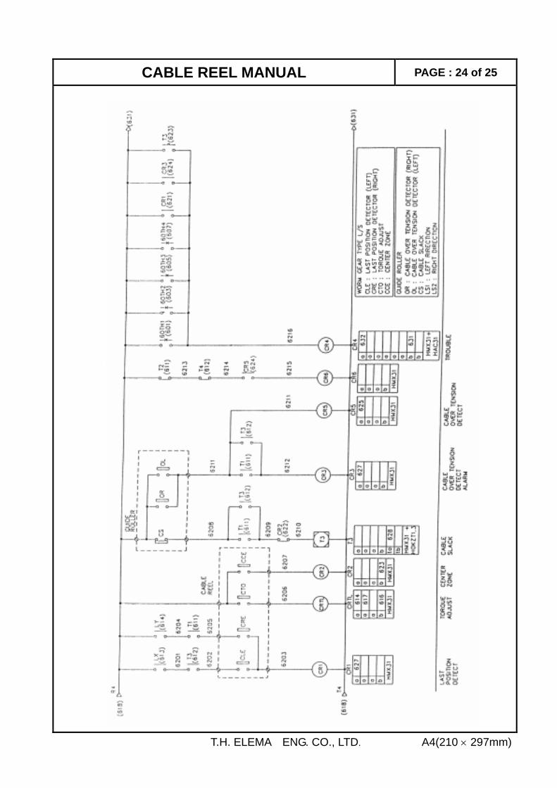
CABLE REEL MANUAL PAGE : 24 of 25
T.H. ELEMA ENG. CO., LTD. A4(210 × 297mm)
CABLE REEL MANUAL PAGE : 25 of 25
T.H. ELEMA ENG. CO., LTD. A4(210 × 297mm)