
C4 NATIONAL BUILDING CODE OF FINLAND
27
1 C4 NATIONAL BUILDING CODE OF FINLAND Thermal insulation Guidelines 2003 Ministry of the Environment Decree on thermal insulation Adopted in Helsinki on the 30th of October 2002 In accordance with the decision of the Ministry of the Environment the following is enacted on the basis of Sec- tion 13 of the Land Use and Building Act (132/1999) of 5th February 1999: One acceptable method in construction is to follow the instructions on thermal insulation in Appendix 1. The proposed instructions have been notified in accordance with Directive 98/34/EC of the European Parlia- ment and of the Council as amended by Directive 98/48/EC laying down a procedure for the provision of infor- mation in the field of technical standards and regulations, and regulations on services of the information society. This decree shall enter into force on the first of October 2003. This decree shall rescind the decision on thermal insulation (C4) by the Ministry of the Interior adopted on the 27th of October 1978. In Helsinki, on the 30th of October 2002 Minister Suvi-Anne Siimes Senior Technical Adviser Raimo Ahokas
Transcript of C4 NATIONAL BUILDING CODE OF FINLAND

1
C4 NATIONAL BUILDING CODE OF FINLAND Thermal insulation Guidelines 2003
Ministry of the Environment Decree on thermal insulation
Adopted in Helsinki on the 30th of October 2002
In accordance with the decision of the Ministry of the Environment the following is enacted on the basis of Sec-tion 13 of the Land Use and Building Act (132/1999) of 5th February 1999: One acceptable method in construction is to follow the instructions on thermal insulation in Appendix 1. The proposed instructions have been notified in accordance with Directive 98/34/EC of the European Parlia-ment and of the Council as amended by Directive 98/48/EC laying down a procedure for the provision of infor-mation in the field of technical standards and regulations, and regulations on services of the information society. This decree shall enter into force on the first of October 2003. This decree shall rescind the decision on thermal insulation (C4) by the Ministry of the Interior adopted on the 27th of October 1978. In Helsinki, on the 30th of October 2002
Minister Suvi-Anne Siimes
Senior Technical Adviser Raimo Ahokas

2
NATIONAL BUILDING CODE OF FINLAND MINISTRY OF THE ENVIRONMENT, Department of Housing and Building
Thermal insulation Guidelines 2003 Content 1 GENERAL 1.1 Scope of application 2 DETERMINATION OF THERMAL
TRANSMITTANCE
2.1 General 2.2 Calculation of thermal transmittance 2.3 Thermal bridges 2.4 Taking into account any air flows in thermal insulation 3 DESIGN OF THERMAL INSULATION AND INSULATING 3.1 Design of thermal insulation 3.2 Handling, storage and installation of thermal insulation materials 3.3 Protection from wind and air flows 4 THERMAL CONDUCTIVITY OF BUILDING MATERIALS 4.1 Values for design thermal conductivity and
4.2 Normative thermal conductivity of building materials 5 THERMAL RESISTANCES 5.1 Surface resistance 5.2 Thermal resistance of air cavity 5.3 Thermal resistance of thin material layers 5.4 Building components against the ground 6 THERMAL TRANSMITTANCE FOR WIN-
DOW, DOOR AND VENTILATION PANEL 6.1 General 6.2 Thermal transmittance for window glazing 6.3 Thermal transmittance for window frame 6.4 Thermal interaction of the frame structure and
glazing 6.5 Mean thermal transmittance for window 6.6 Thermal transmittance for door and ventilation
panel
the options
KEY TO SYMBOLS Guidelines printed in the wide column contain acceptable solutions.
Explanations in italics in the narrow column provide further
information and contain references to provisions, regulations and instructions.
C4

3
DEFINITIONS Thermal insulation material Building material used primarily or in addition to other uses essentially for thermal insulation. Thermal insulation A uniform insulation structure made of one or more thermal insulation materials for a building component. Wind barrier A material layer in a building component with the main purpose of preventing a detrimental flow of air from outside to the internal part of the structure and back. Air barrier A material layer in a building component which prevents a detrimental flow of air through the building component from one side to the other. Explanation Often a material layer in a building component, provided for some other
main purpose, acts as an air barrier. Thermal bridge A structural part in a building component made of material with high thermal conductivity in comparison to the adjacent materials where the steady-state heat flow density due to temperature difference through the surfaces of the building com-ponent is higher in comparison to the adjacent surface area. Linear thermal bridge A thermal bridge with a cross-section which continues uniformly in the direction of the surface of the building component. Point thermal bridge A thermal bridge which is local in structure and with no uniform cross-section in the direction of the surface of the building component. Thermal conductivity (λ), W/(m ⋅ K) Thermal conductivity indicates the density of heat flow in steady-state through a layer of homogenous material with a thickness of a unit of length when the temperature difference between the surfaces of the material layer is a unit of tempera-ture. Mean thermal conductivity (λ10), W/(m ⋅ K) The mean thermal conductivity indicates an arithmetic mean value of individual measurement results for thermal conduc-tivity of a material when measurements are taken at the mean temperature of 10°C. Explanation If the material is hygroscopic or if thermal conductivity of the material
changes with time, the conditions and factors prior to measurements af-fecting the moisture content or the changes to thermal conductivity by ageing must be stated.
Normative thermal conductivity (λn), W/(m ⋅ K) Normative thermal conductivity of a building material refers to a design value of thermal conductivity provided by these guidelines or type approval decisions for calculations in practical building activities. Thermal resistance (R), (m2 ⋅ K)/W Thermal resistance of a material layer of a uniform thickness or a layered structure in the thermal steady-state indicates the temperature difference between the isothermal surfaces on both sides of the structure divided by the heat flow density through the material layer. Internal and external surface resistance (Rsi and Rse), (m2 ⋅ K)/W Indicates the thermal resistance of the border layer between the surface of a building component and the internal or external environment.
4
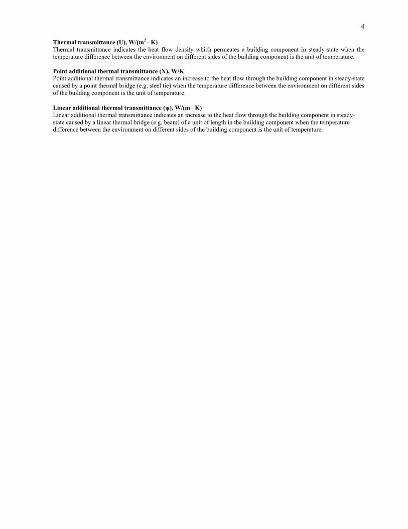
Thermal transmittance (U), W/(m2 ⋅ K) Thermal transmittance indicates the heat flow density which permeates a building component in steady-state when the temperature difference between the environment on different sides of the building component is the unit of temperature. Point additional thermal transmittance (Χ), W/K Point additional thermal transmittance indicates an increase to the heat flow through the building component in steady-state caused by a point thermal bridge (e.g. steel tie) when the temperature difference between the environment on different sides of the building component is the unit of temperature. Linear additional thermal transmittance (ψ), W/(m ⋅ K)
Linear additional thermal transmittance indicates an increase to the heat flow through the building component in steady-state caused by a linear thermal bridge (e.g. beam) of a unit of length in the building component when the temperature difference between the environment on different sides of the building component is the unit of temperature.

5
1 GENERAL 1.1 Scope of application 1.1.1 These instructions concern building components and structures of a building, abutted by the open air and
the ground, and those between different spaces of a building; determining their thermal transmittance, and design and implementation of thermal insulation. The instructions concern practical structures in ac-cordance with good building practices where the effect of minor non-ideal faults are taken into account when calculating U-values.
Explanation These instructions contain an acceptable way to ascertain compliance
with the requirements set for thermal transmittance (U) in Part C3 of the National Building Code of Finland.
The EN standards concerning calculation of thermal transmittance for the
building envelope, building components and structures, and the EN stan-dards supplementing these standards of calculation form a set of instruc-tions according to which the thermal transmittance may also be deter-mined in an acceptable way.
1.1.2 These instructions do not concern calculation of the effects of air flow directed through thermal insula-
tion; of air leaking through the building components from one side to the other; or of solar radiation on the building or of any other heat loads on the structures fluctuating as a function of time.
2 DETERMINATION OF THERMAL TRANSMITTANCE 2.1 General
These instructions provide a method of calculating thermal transmittance (U) for building components and structures. Other methods may also be accepted if these instructions cannot be applied or the re-placement method of calculation is at least as accurate as the one provided here. Test results may also be utilised when the calculation is unreasonably difficult or the input information necessary for calcula-tion is determined experimentally.
Explanation An individual measuring result of thermal transmittance is valid only for
the tested structure under measuring conditions. When the calculation of thermal transmittance is unreasonably difficult, it is, however, possible to estimate the thermal transmittance for a structure applicable to practical design on the basis of test results. Then the aim must be to take into ac-count any inaccuracies in measuring, any practical variations of the characteristics of the structure and the materials used in it, the effects of moisture content of the materials in accordance with the construction de-sign and any possible irreversible changes to thermal conductivity of building materials during the service life.
2.2 Calculation of thermal transmittance 2.2.1 Thermal transmittances (U) for building components are calculated using thermal conductivity design
values determined for building materials provided with a CE mark in accordance with the EN standards; tabulated design values for thermal conductivity stated in the EU standards; values of normative thermal
6
conductivity (λn) or any other thermal conductivity design values suitable for the building component and determined in an acceptable way. If the same material is provided with several λn-values, the value suitable for the target on the basis of footnotes is selected.
Explanation Footnotes relating to the values of normative thermal conductivity are
given in table 1 and in the type approval decisions for normative thermal conductivity of thermal insulation.
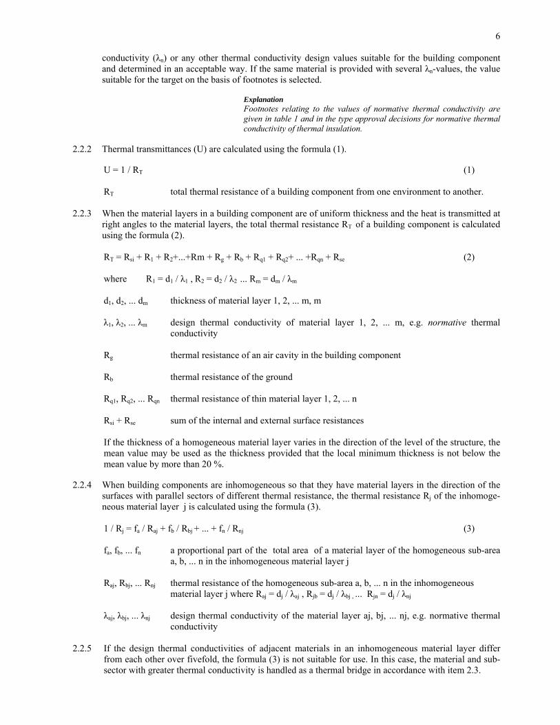
2.2.2 Thermal transmittances (U) are calculated using the formula (1). U = 1 / RT (1) RT total thermal resistance of a building component from one environment to another. 2.2.3 When the material layers in a building component are of uniform thickness and the heat is transmitted at
right angles to the material layers, the total thermal resistance RT of a building component is calculated using the formula (2).
RT = Rsi + R1 + R2+...+Rm + Rg + Rb + Rq1 + Rq2+ ... +Rqn + Rse (2)
where R1 = d1 / λ1 , R2 = d2 / λ2 ... Rm = dm / λm
d1, d2, ... dm thickness of material layer 1, 2, ... m, m
λ1, λ2, ... λm design thermal conductivity of material layer 1, 2, ... m, e.g. normative thermal
conductivity
Rg thermal resistance of an air cavity in the building component
Rb thermal resistance of the ground
Rq1, Rq2, ... Rqn thermal resistance of thin material layer 1, 2, ... n
Rsi + Rse sum of the internal and external surface resistances If the thickness of a homogeneous material layer varies in the direction of the level of the structure, the mean value may be used as the thickness provided that the local minimum thickness is not below the mean value by more than 20 %.
2.2.4 When building components are inhomogeneous so that they have material layers in the direction of the
surfaces with parallel sectors of different thermal resistance, the thermal resistance Rj of the inhomoge-neous material layer j is calculated using the formula (3).
1 / Rj = fa / Raj + fb / Rbj + ... + fn / Rnj (3) fa, fb, ... fn a proportional part of the total area of a material layer of the homogeneous sub-area
a, b, ... n in the inhomogeneous material layer j Raj, Rbj, ... Rnj thermal resistance of the homogeneous sub-area a, b, ... n in the inhomogeneous
material layer j where Raj = dj / λaj , Rjb = dj / λbj , ... Rjn = dj / λnj
λaj, λbj, ... λnj design thermal conductivity of the material layer aj, bj, ... nj, e.g. normative thermal
conductivity
2.2.5 If the design thermal conductivities of adjacent materials in an inhomogeneous material layer differ from each other over fivefold, the formula (3) is not suitable for use. In this case, the material and sub-sector with greater thermal conductivity is handled as a thermal bridge in accordance with item 2.3.

7
2.2.6 The total thermal resistance RT of building components containing inhomogeneous layers is calculated using the formula (4) and the thermal transmittance U using the formula (1).
RT = Rsi + R1 + R2+...+Rn + ΣR + Rse (4) R1, R2, ... Rn thermal resistance of the inhomogeneous material layer 1, 2, ... n calculated using the
formula (3) ΣR the sum of thermal resistances of homogeneous material layers, air cavity, thin material layers and the ground Rsi + Rse the sum of the internal and external surface resistances
Explanation The RT-value calculated using the formula (4) is the lower approximate
value.
2.3 Thermal bridges 2.3.1 Regularly repeated thermal bridges in the structure when they are characteristic to it are taken into ac-
count when ascertaining conformity of the thermal transmittances. This concerns, for instance, ties, brackets and supporting struttings and frames which are typical to the structure in the entire area of the envelope represented by it.
2.3.2 When calculating thermal transmittances, there is no need to take into account any individual thermal
bridges in the building envelope, made for various reasons. An individual thermal bridge may be formed by a junction between the base floor or ceiling and the external wall; a balcony support; a col-umn cutting through the base floor; a component for building service technology and any other such like separately designed and implemented single component in the structure.
Explanation The temperature of the structure at the point of a thermal bridge is differ-
ent in respect of the surrounding structure. The result of this could be a local decrease in thermal comfort, the surface getting dirty and, at its worst, moisture condensing on the inside surface of the structure or deeper in the structure. In respect of all thermal bridges, the structures are designed in such a way that there are no moisture problems, referred to, and that the thermal conditions in accordance with Part D2 of the Na-tional Building Code is achieved in the occupied zone.
. 2.3.3 When the design thermal conductivity of the thermal bridge material is different from the corresponding
design value of the adjacent material over fivefold, the increase ∆UΨΧ of the thermal transmittance for building components due thermal bridges is calculated using the formula (6).
∆UΨΧ = ΣΨk (lk / A) + ΣΧj (nj / A) (6)
Ψk linear additional thermal transmittance of a linear thermal bridge k in the building component,
similar with each other, W/(m · K) Xj point additional thermal transmittance of a point thermal bridge j in the building component,
similar with each other, W/K lk total length of similar linear thermal bridges in the building component, m
nj number of similar point thermal bridges in the building component
A area of the building component, m2

8
Additional thermal transmittance of linear and point thermal bridges (Ψk, Xj) is calculated using a method of calculation appropriate for the purpose or is determined by experiment.
2.3.4 For instance, metal braces and ties cause thermal bridges. It may be assumed that the thermal transmit-
tance U of building components increases by 0.006 W/(m2 · K) when using 4 stainless steel ties of 4 mm diameter per m2 and by 0.05 W/(m2 · K) when using 4 copper ties of 4 mm diameter per m2.
2.4 Taking into account any air flows in thermal insulation 2.4.1 If the effect of air flows in small cracks, air gaps and air permeable insulation material of thermal insula-
tion, is not taken into account in the value for design thermal conductivity, the effect of air flows which increases the heat loss is separately assessed and taken into account as an increase in the thermal trans-mittance for building components.
Explanation The EN standard concerning calculation of thermal transmittance re-
quires that the effects of imperfection of thermal insulation are taken into account when calculating thermal transmittance.
Normative thermal conductivity (λn) of thermal insulation material takes
into account the effect of slight air flows in thermal insulation. 2.4.2 The size of the increase (∆Ug) added to the thermal transmittance (U) in order to take into account the
effect of air flows in thermal insulation, depends on the installation method of thermal insulation, pro-tection of the insulation and air permeability of the insulation material. When assessing the size of the increase, it is based on reliable examination or investigation.
3 DESIGN OF THERMAL INSULATION AND INSULATING 3.1 Design of thermal insulation 3.1.1 Thermal insulation materials should be suitable for their use and in accordance with the requirements
imposed. They should retain their characteristics for the service life of the structure. In respect of realisa-tion of the requirements, the designs provide sufficient information on the thermal insulation materials used, on the structure of thermal insulation and dimensions and, if necessary, on the details of carrying out the insulation works.
3.1.2 During both the construction stage and the use of the structures, the loads directed at thermal insulation
materials are taken into account when selecting and protecting the insulation materials. Any possible permanent unavoidable but acceptable changes to the characteristics of thermal insulation are taken into account when dimensioning the insulation.
3.1.3 Values of design thermal conductivity determined in accordance with the EN standards are used as de-
sign values for thermal insulation materials provided with a CE mark. The values for normative thermal conductivity (λn), suitable for the structure under review on the basis of their description of installation and protection methods, or any other suitable values for design thermal conductivity, determined in an acceptable way, are used as design values for other insulation materials. The designs are drawn up in sufficient detail so that they show the method of installation and protection required by the selection of λn-values.
3.1.4 The designs itemise the intended thermal insulation materials or advise of the characteristics required
from insulation materials. When designing spaces for thermal insulation in the structures, the aim is for solutions where insulation may be carried out using working methods suitable for the chosen insulation material. In difficult cases, the working method is provided. The expected settlement of mineral or wood

9
fibre insulation installed into open insulation space of upper floor by dry blowing is taken into account by making the insulation thickness blown correspondingly greater than planned.
3.2 Handling, storage and installation of thermal insulation materials 3.2.1 At the building site, the compliance with the design of thermal insulation materials is checked and the
insulation materials are protected from getting wet and damaged. The quality of insulation materials, dif-ferent from the design or insufficiently identifiable, should be ascertained as equivalent to the design, before use.
3.2.2 Before installation of thermal insulation materials, the insulation spaces of the structures are checked
and any possible defects are mended. During installation, special care is taken so that the insulation ma-terial fills the space provided for it as perfectly as possible. The joints in insulation installed in several layers are overlapped. Possible errors and defects are mended using the same or corresponding insula-tion material.
3.2.3 Insulation work should be timed in such a way that the structures protecting thermal insulation are com-
pleted or they are made without delay after insulation. If necessary, temporary protection is used. Com-pleted insulation must not be loaded damagingly nor pressed thinner than designed. Installation of fibre insulation blown into the open insulation space of upper floor is completed when the structures protect-ing from wind and rain are sufficiently complete and the works that require walking in the insulated area are finished. The insulation thickness blown is checked with measurements and is compared with the de-sign taking into account the allowance for settlement. If necessary, the insulated area is subsequently provided with walkways.
3.3 Protection from wind and air flows 3.3.1 If application of values for design thermal conductivity of thermal insulation materials require protection
against wind and the structure has no layer made for any other purpose, also functioning as wind barrier, the thermal insulation is protected by a separate wind barrier. The air permeance for wind barrier may be 10 ⋅ 10-6 m3/(m2 · s · Pa) at the most.
3.3.2 Wind barrier refers to a layer attached to thermal insulation and entirely covering it. This must not have
any open gaps or holes running to thermal insulation. Particular attention is paid to air tightness of the joints in wind barrier, in lower edge of the walls and corners and in jambs of lead-ins of window and door openings etc.
3.3.3 Joints and edges of wind barrier made of sheets are fitted, if possible, against the rigid surface. Fixings
and their distances are chosen in such a way that the joints will not open after installation. Joints in thin wind barriers made of board etc. are sealed, for instance, by overlapping and compressing between the rigid surfaces. This or a corresponding method, which guarantees tightness, is also applied to the edges and corners of wind barrier.
3 3.4 It is often appropriate to lift the upper edge of wind barrier for external walls over the upper surface of
the thermal insulation of the upper floor to protect the edges of the insulation. If there is a large ventilat-ing air gap (height ≥ 200 mm) above horizontal or slightly pitched upper floor and this is surrounded by eaves structure throttling the ventilating air flow (e.g. conventional gap boarding), the continuous wind barrier may be omitted when the conditions of value for the design thermal conductivity of thermal insu-lation material so allows. However, it is advisable to fix wind directing strips, controlling the ventilating air flows, to the eaves edges if the air flow may hamper functioning of thermal insulation or if the insu-lation material is moving in the wind.
3.3.5 To prevent uncontrolled air leakages through the structure from one side to the other, at least one layer
functioning as an air barrier is needed in the structure. Often, this is on the warm side of thermal insula-tion. Unless the structure has a separate air barrier it is necessary that air tightness of at least one layer attached to thermal insulation is sufficient in order to function as such.
10
3.3.6 Air tightness of an air barrier is designed and implemented as sufficient, so that when the ventilation system is used in accordance with the design, the system is able to keep the interior of the building, as a general rule, under negative pressure in respect of outdoors, and the thermal conditions in accordance with Part D2 of the National Building Code is achieved in the occupied zone.
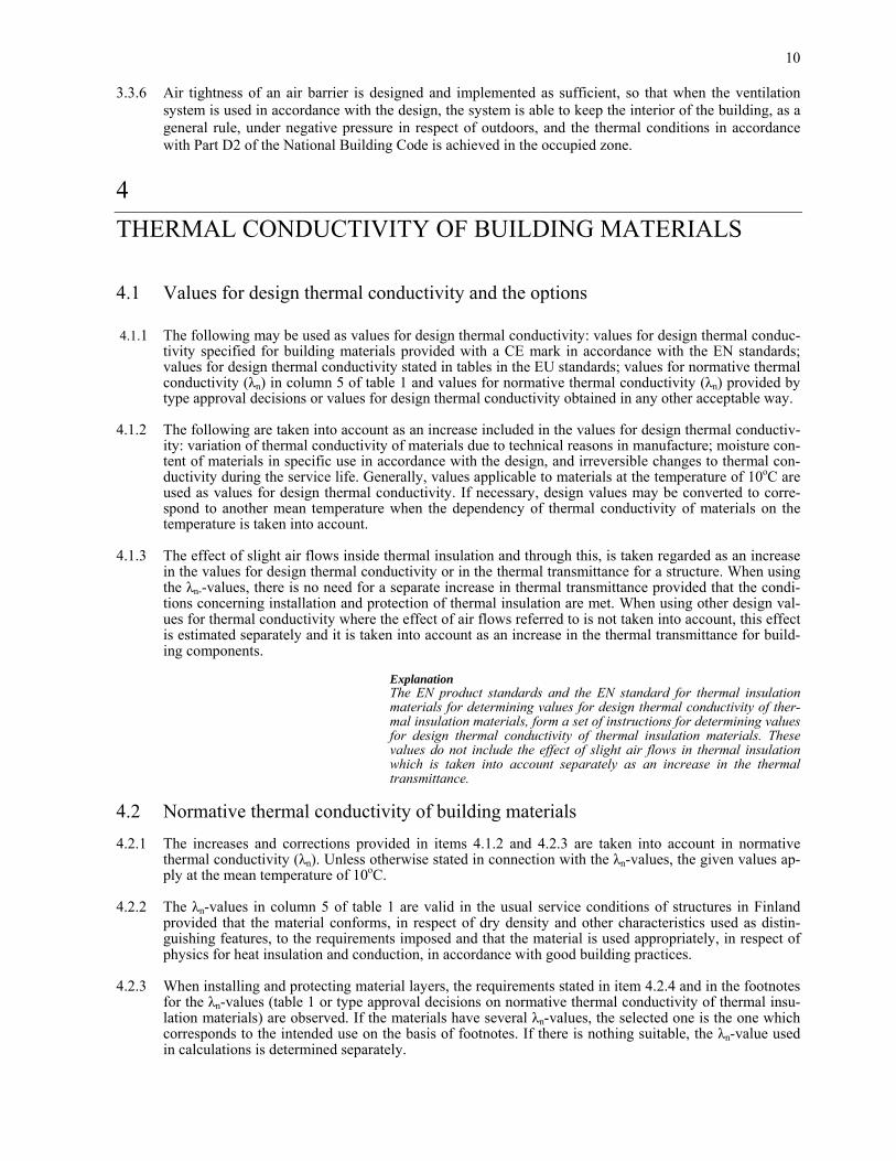
4 THERMAL CONDUCTIVITY OF BUILDING MATERIALS 4.1 Values for design thermal conductivity and the options 4.1.1 The following may be used as values for design thermal conductivity: values for design thermal conduc-
tivity specified for building materials provided with a CE mark in accordance with the EN standards; values for design thermal conductivity stated in tables in the EU standards; values for normative thermal conductivity (λn) in column 5 of table 1 and values for normative thermal conductivity (λn) provided by type approval decisions or values for design thermal conductivity obtained in any other acceptable way.
4.1.2 The following are taken into account as an increase included in the values for design thermal conductiv-
ity: variation of thermal conductivity of materials due to technical reasons in manufacture; moisture con-tent of materials in specific use in accordance with the design, and irreversible changes to thermal con-ductivity during the service life. Generally, values applicable to materials at the temperature of 10oC are used as values for design thermal conductivity. If necessary, design values may be converted to corre-spond to another mean temperature when the dependency of thermal conductivity of materials on the temperature is taken into account.
4.1.3 The effect of slight air flows inside thermal insulation and through this, is taken regarded as an increase
in the values for design thermal conductivity or in the thermal transmittance for a structure. When using the λn--values, there is no need for a separate increase in thermal transmittance provided that the condi-tions concerning installation and protection of thermal insulation are met. When using other design val-ues for thermal conductivity where the effect of air flows referred to is not taken into account, this effect is estimated separately and it is taken into account as an increase in the thermal transmittance for build-ing components.
Explanation The EN product standards and the EN standard for thermal insulation
materials for determining values for design thermal conductivity of ther-mal insulation materials, form a set of instructions for determining values for design thermal conductivity of thermal insulation materials. These values do not include the effect of slight air flows in thermal insulation which is taken into account separately as an increase in the thermal transmittance.
4.2 Normative thermal conductivity of building materials 4.2.1 The increases and corrections provided in items 4.1.2 and 4.2.3 are taken into account in normative
thermal conductivity (λn). Unless otherwise stated in connection with the λn-values, the given values ap-ply at the mean temperature of 10oC.
4.2.2 The λn-values in column 5 of table 1 are valid in the usual service conditions of structures in Finland
provided that the material conforms, in respect of dry density and other characteristics used as distin-guishing features, to the requirements imposed and that the material is used appropriately, in respect of physics for heat insulation and conduction, in accordance with good building practices.
4.2.3 When installing and protecting material layers, the requirements stated in item 4.2.4 and in the footnotes
for the λn-values (table 1 or type approval decisions on normative thermal conductivity of thermal insu-lation materials) are observed. If the materials have several λn-values, the selected one is the one which corresponds to the intended use on the basis of footnotes. If there is nothing suitable, the λn-value used in calculations is determined separately.

11
4.2.4 In table 1, the λn-values provided for thermal insulation materials concern products with no valid type approval of λn-values. In respect of the requirements for the method of installation and protection of thermal insulation materials, the footnote 1) in table 1 refers to the following requirements which may be deviated from in situations subject to other footnotes in table 1.
• one surface of insulation (usually the inner surface) is always attached to a tight surface in respect
of air flows (e.g. concrete, brickwork, tight board, plastic membrane, insulation paper • one surface of vertical and sloped insulations (slope with respect to the horizontal > 30 o) has wind
barrier [air permeance ≤ 10 ⋅ 10-6 m3/(m2 ⋅ s ⋅ Pa) unless otherwise allowed for in the conditions for normative thermal conductivity of thermal insulation materials] such as a building board with nail fixings or building paper with pressed and overlapped joints
• there is a wide air cavity, provided with an eaves or border structure throttling the air flow, above the upper floor insulation with a maximum slope of 30o with respect to the horizontal. The height of this cavity is in all areas a minimum of 200 mm (however, right at the eaves borders, a mini-mum of 50 mm)
• there is an air cavity in all areas underneath the insulation in the base floor with crawl space. All the edges of this cavity are protected by a uniform foundation wall provided with ventilation holes or a corresponding protective structure
• there is a drainage layer preventing capillary rise of moisture, underneath the thermal insulation of the permanently dry base floor against the ground in the heated space
4.2.5 If the mean moisture content of the material is higher than the value given in column 4 of table 1, the λn-
value is correspondingly increased on the basis of a separate research. 4.2.6 The λn-values of materials do not normally include thermal transmittance through other structural ele-
ments and materials (support structures, jointing compounds, ties, fixtures etc.) permeating through a material layer or abutted to it nor the effect of thinning of a material layer (settlement, external pressure etc.) unless stated in the footnotes of table 1. The said factors are taken into account when calculating thermal transmittances.
4.2.7 The dry density in table 1 refers to the maximum permitted mean dry density of a material or the limits
between which the mean dry density may vary. In respect of masonry walls, the column of dry density indicates the dry density of a masonry block. A gross density is used as a dry density of a perforated brick, i.e. mass divided with volume without taking into account a deduction for the holes.
4.2.8 The moisture content (wn) refers to a mean moisture content accumulated in the material during the use
in accordance with the design. Its effect is taken into account in the λn-value.

12
TABLE 1. NORMATIVE THERMAL CONDUCTIVITY OF BUILDING MATERIALS. 1 2 3 4 5 6 Material Dry density Thermal Moisture Normative Footnote conductivity content thermal conductivity ρ λ10 wn λn kg/m3 W/(m ⋅ K) % of dry W/(m ⋅ K) weight THERMAL INSULATION MATERIALS cork board (expanded) 150 0.035 3 0.045 1) 3 0.050 2) 200 0.040 3 0.050 1) 3 0.055 2) wood wool board 150�350 0.070 8 0.080 3) 8 0.10 4) wood fibre board, bituminous 350 0.055 10 0.065 5) wood fibre board, porous 300 0.045 10 0.055 5) mineral wool board 10�300 0.045 0.5 0.055 1) and mat 8) 0.5 0.060 2) 0.070 6) 0.10 7) cellular plastic board, expanded polystyrene 30�60 0.033 2 0.041 1) 2 0.045 2) 0.050 6) 0.060 7) 17�29.9 0.037 2 0.045 1) 2 0.050 2) 0.055 6) 0.065 7) 13�16.9 0.041 2 0.050 1) 2 0.055 2) 0.065 6) cellular plastic board, extruded polystyrene propellant CFC 12 x) 22�45 0.030 2 0.037 1) 2 0.041 2) or 6) 0.045 7) 0.050 9) other propellant 22�45 0.037 2 0.045 1) 2 0.050 2) or 6) 0.055 7) 0.060 9) 1) Insulation is protected in accordance with the requirements described in 4.2.4 2) One side of insulation is attached to a tight surface and the other side has an air cavity or space other than the air cav-
ity of the upper floor or the base floor with crawl space, referred to in 4.2.4.
13
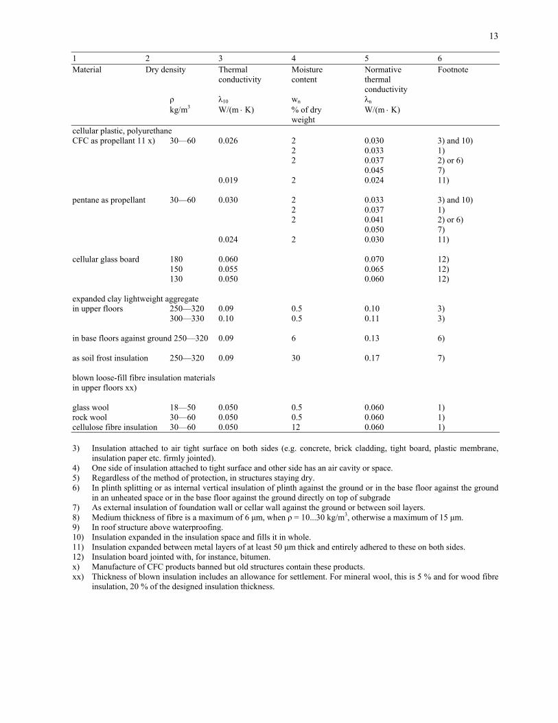
1 2 3 4 5 6 Material Dry density Thermal Moisture Normative Footnote conductivity content thermal conductivity ρ λ10 wn λn kg/m3 W/(m ⋅ K) % of dry W/(m ⋅ K) weight cellular plastic, polyurethane CFC as propellant 11 x) 30�60 0.026 2 0.030 3) and 10) 2 0.033 1) 2 0.037 2) or 6) 0.045 7) 0.019 2 0.024 11) pentane as propellant 30�60 0.030 2 0.033 3) and 10) 2 0.037 1) 2 0.041 2) or 6) 0.050 7) 0.024 2 0.030 11) cellular glass board 180 0.060 0.070 12) 150 0.055 0.065 12) 130 0.050 0.060 12) expanded clay lightweight aggregate in upper floors 250�320 0.09 0.5 0.10 3) 300�330 0.10 0.5 0.11 3) in base floors against ground 250�320 0.09 6 0.13 6) as soil frost insulation 250�320 0.09 30 0.17 7) blown loose-fill fibre insulation materials in upper floors xx) glass wool 18�50 0.050 0.5 0.060 1) rock wool 30�60 0.050 0.5 0.060 1) cellulose fibre insulation 30�60 0.050 12 0.060 1) 3) Insulation attached to air tight surface on both sides (e.g. concrete, brick cladding, tight board, plastic membrane,
insulation paper etc. firmly jointed). 4) One side of insulation attached to tight surface and other side has an air cavity or space. 5) Regardless of the method of protection, in structures staying dry. 6) In plinth splitting or as internal vertical insulation of plinth against the ground or in the base floor against the ground
in an unheated space or in the base floor against the ground directly on top of subgrade 7) As external insulation of foundation wall or cellar wall against the ground or between soil layers. 8) Medium thickness of fibre is a maximum of 6 µm, when ρ = 10...30 kg/m3, otherwise a maximum of 15 µm. 9) In roof structure above waterproofing. 10) Insulation expanded in the insulation space and fills it in whole. 11) Insulation expanded between metal layers of at least 50 µm thick and entirely adhered to these on both sides. 12) Insulation board jointed with, for instance, bitumen. x) Manufacture of CFC products banned but old structures contain these products. xx) Thickness of blown insulation includes an allowance for settlement. For mineral wool, this is 5 % and for wood fibre
insulation, 20 % of the designed insulation thickness.

14
1 2 3 4 5 6 Material Dry density Thermal Moisture Normative Footnote conductivity content thermal conductivity ρ λ10 wn λn kg/m3 W/(m ⋅ K) % of dry W/(m ⋅ K) weight AERATED CONCRETE as elements in upper floor above 400 0.095 4 0.10 dry rooms 450 0.11 4 0.12 500 0.12 4 0.135 600 0.15 4 0.175 in base floor against 450 0.11 4 0.12 unheated space 500 0.12 4 0.135 600 0.15 4 0.175 in external wall 400 0.095 6 0.105 above ground 450 0.11 6 0.125 500 0.12 6 0.14 with external lining in 400 0.095 4 0.10 14) external wall above ground 450 0.11 4 0.12 14) 500 0.12 4 0.135 14) in external wall below 500 0.12 10 0.16 13) ground as blocks with thin and glued joints indoors and with 400 0.11 4 0.12 14) external lining outdoors 450 0.12 4 0.13 14) 500 0.13 4 0.145 14) 600 0.16 4 0.185 14) above ground 400 0.11 6 0.125 15) 450 0.12 6 0.135 15) 500 0.13 6 0.15 15) below ground 500 0.13 10 0.17 13) 600 0.16 10 0.20 13) 13) Concerns bitumen coated cellar walls when the cellar is heated and well ventilated. If the cellar walls are provided
with a material layer which stops capillary absorption but allows diffusion (e.g. mineral wood or a board forming an air cavity), thermal conductivity in column 5 may be deducted by 0.02 W/(m ⋅ K).
14) Lining refers to a panel facing outside a well ventilated air cavity. 15) Concerns plastered walls, not exposed to driving rain. Unless the walls exposed to driving rain are protected from
water penetration, the λn-value must be increased from the given value by 4 % for aerated concrete and 2.5 % for lightweight-aggregate concrete per each increase of a percentage of moisture content.

15
1 2 3 4 5 6 Material Dry density Thermal Moisture Normative Footnote conductivity content thermal conductivity ρ λ10 wn λn kg/m3 W/(m ⋅ K) % of dry W/(m ⋅ K) weight LIGHTWEIGHT-AGGREGATE CONCRETE as elements above ground 800 0.22 4 0.24 15) 650 0.18 4 0.20 15) below ground 800 0.22 10 0.29 16) 650 0.18 10 0.23 16) lightweight aggregate blocks as blockwork joints of 10 mm external walls filled joints 650 0.22 4 0.24 15) open joints 650 0.18 4 0.20 15) cellar walls or foundation wall filled joints 650 0.22 7 0.25 open joints 650 0.18 7 0.21 dense lightweight-aggregate concrete 1600 0.60 3 0.70 cast-in-situ 1400 0.48 3 0.55 15) or as elements 1200 0.39 3 0.45 16) 1000 0.30 3 0.35 insulations of cast lightweight-aggregate concrete in upper and base floor 600 0.16 2 0.17 500 0.12 2 0.13 400 0.10 2 0.11 against the ground 600 0.16 6 0.19 500 0.12 6 0.15 400 0.10 6 0.12 SAWDUST CONCRETE in dry space 1300 0.35 1 0.45 FILLERS 17) lightweight concrete chippings 400 4 0.15 cinder stone 700 3 0.25 18) cutter chips, 80 12 0.14 loose 120 12 0.08 compacted 250 0.5 0.12 18) blast-furnace slag, 150 0.5 0.10 18) granulated sawdust, loose 120 12 0.12 compacted 200 12 0.08 cellular plastic chips of polystyrene 10�20 2 0.08 16) Concerns external insulation of concrete foundation wall.

16
1 2 3 4 5 6 Material Dry density Thermal Moisture Normative Footnote conductivity content thermal conductivity ρ λ10 wn λn kg/m3 W/(m ⋅ K) % of dry W/(m ⋅ K) weight BUILDING BOARDS fibrous cement board 1800 0.40 2 0.60 800 0.13 4 0.19 600 0.12 4 0.18 gypsum board 800 0.20 0.21 900 0.22 0.23 wood gypsum board 1200 0.24 0.25 cement chipboard 1100 0.21 7 0.23 chipboard 600 0.13 9 0.14 wood fibre board hard 1000 0.12 8 0.13 semi-hard 800 0.10 0.11 plywood birch plywood 700 0.15 8 0.16 mixed plywood 600 0.13 8 0.14 spruce plywood 500 0.12 8 0.13 MISCALLANEOUS BUILDING MATERIALS asphalt 2200 0.7 concrete 2000 2 1.2 2300 2 1.7 perforated concrete blocks as blockwork 1400 0.42 3 0.55 non-perforated concrete blocks as blockwork 2000 0.70 2 1.2 bitumen 1000 0.13 calcium silicate blocks as blockwork 1900 0.70 3 0.95 plaster mortars cement mortar 2000 0.70 2 1.2 gauged mortar 1800 0.65 2 1.0 lime mortar 1700 0.50 2 0.90 burnt bricks as brickwork perforated bricks 1500 0.50 1 0.60 1300 0.45 1 0.50 1700 0.60 1 0.70 non-perforated bricks 1500 0.55 1 0.65 1300 0.50 1 0.60 17) Thermal conductivity provided only applies to fillers in dry spaces. If the material is in contact with the ground,
thermal conductivity is determined on the basis of the corresponding higher water content. 18) When using fillers as insulation of the upper floor without an air tight layer above, 0.02 W/(m ⋅ K) must be added to
the λn-value.

17
1 2 3 4 5 6 Material Dry density Thermal Moisture Normative Footnote conductivity content thermal conductivity ρ λ10 wn λn kg/m3 W/(m ⋅ K) % of dry W/(m ⋅ K) weight timber, pine, spruce 450 0.10 14 0.12 metals copper (pure) 8900 370 aluminium (pure) 2700 220 duralumin (3 - 5 % of copper) 2700 160 brass 8400 120 zinc 7100 110 tin 7300 65 iron, steel 7900 50 lead 11300 35 stainless steel 7900 17
plastics acrylic 1050 0.20 polycarbonate 1200 0.21 PTFE 2200 0.23 PVC, rigid 1390 0.18 PVC, 40 % plasticizer 1200 0.14 polyethylene HD 980 0.40 polyethylene LD 920 0.32 polystyrene 1050 0.18 polyacetate 1410 0.30 phenolic resin 1600 0.5 polypropylene 910 0.22 EPDM 1150 0.20 PMMA (acrylate) 1180 0.18 polyurethane 1200 0.25 polyamide 1130 0.25 epoxy resin 1200 0.23 silicone 1200 0.30 rubbers polyisobutylene 920 0.13 butylene 1200 0.24 polysulfide 0.19 neoprene 1240 0.23 glass 2500 1.0 sealing and insulating compounds nylon 1140 0.23 urethane (liquid) 0.36 silicone foam 0.12 vinyl (flexible) 0.12 polyethylene foam 36 0.06 earth materials clay or silt 1500 1.5 sand, gravel, moraine 2000 2.0

18
1 2 3 4 5 6 Material Dry density Thermal Moisture Normative Footnote conductivity content thermal conductivity ρ λ10 wn λn kg/m3 W/(m ⋅ K) % of dry W/(m ⋅ K) weight types of rock basalt 2800 3.5 limestone 2300 2.5 granite 2700 2.8 sandstone 2300 2.0 natural pumice 400 0.08 water, 10oC 0.6 ice, 0oC 2.2 ice, -10oC 2.5 snow, soft 200 0.12 snow, compacted 500 0.70
5 THERMAL RESISTANCES 5.1 Surface resistance 5.1.1 The values given in table 2 are used as surface resistances for building components abutting to the out-
side. TABLE 2. INTERNAL AND EXTERNAL SURFACE RESISTANCE Rsi AND Rse. Internal surface resistance External surface resistance Rsi, (m2 ⋅ K)/W Rse, (m2 ⋅ K)/W
Direction of the heat flow horizontal upwards downwards horizontal upwards downwards 0.13 0.10 0.17 0.04 0.04 0.04 Intermediate values 0o � 90o are obtained by linear interpolation. 5.2 Thermal resistance of air cavity 5.2.1 Unventilated air cavity is a closed air gap in a building component with no opening for airflow coming
from the outside. 5.2.2 Air cavity with no thermal insulation in its external part of the structure and with small openings from
the outside, may be taken into account as unventilated air cavity in respect of its thermal resistance. In this case, the openings may not be located in such a way that they allow a ventilating air flow through air cavity from one side to the other. In addition, it is understood that the combined size of the openings does not exceed the following limit values.
• 5 cm2/m per unit of length of vertical air cavity in a vertical structure • 5 cm2/m2 per unit of area of horizontal air cavity
5.2.3 The values given in table 3 are used as thermal resistance of unventilated air cavity.

19
TABLE 3. THERMAL RESISTANCE Rg OF UNVENTILATED AIR CAVITY Emissivity of Thickness of Thermal resistance Rg, (m2 ⋅ K)/W abutting air cavity ___________________________________________________________ surfaces. dg mm Direction of heat flow horizontal upwards downwards usual case: 5 0.11 0.11 0.11 non-reflective 10 0.15 0.15 0.15 surfaces 20 0.17 0.16 0.18 ε > 0.8 50�100 0.18 0.16 0.21 one surface 5 0.17 0.17 0.17 reflective 10 0.27 0.23 0.29 20 0.36 0.25 0.43 ε < 0.2 50�100 0.34 0.27 0.61 The values given lower in table 3 only apply if the reflective surface stays clean all the time and its emissivity remains under 0.2. 5.2.4 Ventilated air cavity is an air gap in a building component with ventilating airflow through it from one
edge of a building component to the other. Ventilated air cavity is either slightly ventilating or well ven-tilating depending on the size of the openings leading to the air gap.
5.2.5 Air cavity is slightly ventilating when the area of the opening abutting to the open air is within the fol-
lowing limits:
• more than 5 cm2/m but a maximum of 15 cm2/m per unit of length of vertical air cavity in a verti-cal structure
• more than 5 cm2/m2 but a maximum of 15 cm2/m2 per unit of area of horizontal air cavity
5.2.6 A half of thermal resistance of corresponding unventilated air cavity given in table 3 may be taken into account as thermal resistance of slightly ventilating air cavity. If thermal resistance of a structure from the air cavity to the environment outside is greater than 0.15 (m2 · K)/W, the value of 0.15 (m2 · K)/W is used in calculations for this part of the structure.
5.2.7 The combined size of the openings leading to well ventilated air cavity is greater than 15 cm2/m (vertical
structures) or 15 cm2/m2 (horizontal structures). 5.2.8 If a structure has a well ventilated air cavity, its thermal resistance or that of the part of the building
component outside the air cavity may not be taken into account when calculating the total thermal resis-tance of a structure. In this case, the values for internal surface resistance (Rsi) in table 2 may be used as a surface resistance of the surface of the internal part of the structure abutting the air cavity.
5.2.9 Thermal resistance of air cavity ventilated mechanically must not be taken into account in calculations
unless the effect that the air cavity and the material layer outside it have on the structure, is clarified separately.
5.2.10 The effect of ventilation on the total thermal resistance of a structure may be determined on the basis of
a separate investigation when the instructions given here are not well suited (e.g. ventilation grooves ) or the method used gives a more accurate result compared to the instructions.
5.2.11 With a roof structure where there is an air space left between a thermally insulated, generally horizontal
upper floor and a sloping roof, the air space may be regarded as a thermally homogeneous cavity with thermal resistance in accordance with table 4.

20
TABLE 4. THERMAL RESISTANCE Rg OF THE ROOF AIR SPACE Type of roof structure Thermal resistance Ru, (m2 ⋅K)/W 1. tiled roof, felt roof in sections or equivalent, with 0.2 roofing underlay or a corresponding material layer 2. as in 1, but the lower surface of the roofing underlay is a low emissivity surface such as an aluminium layer 0.3 3. continuous roofing of flexible sheets of bitumen or corresponding 0.3 roofing without gaps Explanation Values in table 4 concern ventilated air space and a roof structure above
it. The values do not include the external surface resistance (Rse). 5.3 Thermal resistance of thin material layers 5.3.1 Thin, comparatively air tight material layers include, for instance, plastic membranes, building papers,
felt and cardboard layers with the maximum air permeance of 10 ⋅ 10-6 m3/(m2 ⋅ s ⋅ Pa). Their thermal re-sistance is given in table 5.
TABLE 5. THERMAL RESISTANCE Rq OF THIN MATERIAL LAYER Location of a material layer Thermal resistance Rq,(m2 ⋅ K)/W One surface against a rigid surface, 0.02 e.g. against a wall in timber boarding*) Between rigid surfaces*) 0.04 *) Thermal resistance includes both the thermal resistance of a material layer and the thermal resistance of a thin air
cavity formed between this and the rigid surface, the layer of timber boarding etc. 5.4 Building components against the ground 5.4.1 The building components against the ground should be well functioning in respect of heat and moisture
physical properties in such a way that the desired level of insulation is achieved, and moisture, frost heaving and coldness of the surfaces do not cause any harm. When designing and implementing, the shape of the ground surface, the characteristics of the soil, the level of ground water and running of sur-face waters are taken into account.
5.4.2 The temperature of the inner surface of a structure near the junction of the external wall and the floor
against the ground must not fall too low in respect of comfort. Thermal insulation of the outside wall, base floor and foundation wall is located, in respect of each other, in such a way that no detrimental thermal bridge exsists in the junction of the structures.
5.4.3 If the depth of the foundation of a heated building on frost-susceptible ground is left above the natural,
frost-free depth, the foundations are protected with frost insulation. The insulation material used and the location and thermal resistance of insulation are chosen with the object that the building will function for its service life in accordance with the design.
5.4.4 Unless more detailed calculations or tests are carried out, the total thermal resistance of the building
components against the ground is calculated in accordance with items 5.4.5 .... 5.4.11.

21
5.4.5 It is assumed that the base floor and the cellar wall are divided into edge and inner zones in accordance with figures 1 and 2. The values in table 6 are used as the thermal resistance (Rb) of the ground. The val-ues include the external surface resistance (Rse). It is required then that the foundations and the base floor are permanently dried using appropriate solutions for drainage and conveyance of surface water. Also, the inspection pipes and wells of the drainage system should be covered with an air tight cover, a layer of earth, a layer of insulation etc. to prevent access of outside air and frost heaving.
5.4.6 When calculating the thermal resistance of a floor against the ground and an external cellar wall, the
thermal resistance of the ground may be taken into account. In this case, the values for thermal resis-tance in table 6 are used unless more detailed calculations or tests regarding heat flow under the building are carried out.
5.4.7 The values given in columns 3 and 4 of table 6 are used as the thermal resistance of the ground under the
base floor against the ground. Correspondingly, the values given in columns 5 and 6 of table 6 are used as the thermal resistance of the ground outside the cellar wall.
5.4.8 The values in table 6 may be used if the bottom surface of the floor structure is a maximum of 300 mm
above the adjacent ground surface level and the thickness of the earth layer under the drainage layer is a minimum of 1 m.
Explanation The surface of a structure against the top surface of the drainage layer is
regarded as the bottom surface of the floor structure.
5.4.9 When calculating the thermal resistance of a floor structure and the ground, it is assumed that the ground begins below the drainage layer, however, a maximum of 200 mm below the bottom surface of a floor structure.
5.4.10 Thermal resistance of a drainage layer of gravel or shingles with a minimum thickness of 200 mm is
0.2 (m2 ⋅ K)/W. 5.4.11 If the cellar floor is situated a minimum of 1 m below the ground surface level, the values given for an
inner zone in column 4 of table 6 may be used as thermal resistance Rb. For the cellar floor situated higher, the same values, as those in item 5.4.5 for the floor on the ground surface level, are used.
Figure 1. Division of the base floor against the ground into zones reuna-alue = edge zone; sisäalue = inner zone

22
Figure 3. Division of the part of a wall against the ground into zones reuna-alue = edge zone; sisäalue = inner zone TABLE 6. THERMAL RESISTANCE Rb OF THE GROUND WHEN THE FOUNDATIONS AND BASE FLOOR ARE PERMANENTLY DRIED.
Thermal resistance Rb of the ground m2K/W Ground below base floor
Ground adjacent to foundation wall
Type of soil
Normative thermal conductivity λn W/m K
edge zone
inner zone
edge zone
inner zone
1 2 3 4 5 6 Clay Sand and gravel, drained Silt and fine sand Sand and gravel, not drained Moraine Rock
1.4 2.3 3.5
0.8 0.50 0.30
3.20 2.00 1.20
0.40 0.25 0.15
1.60 1.00 0.60
6 THERMAL TRANSMITTANCE FOR WINDOW, DOOR AND VENTILATION PANEL 6.1 General 6.1.1 In respect of the object of design, conformity with the regulations regarding each type of window, door
and ventilation panel with a different structure is ascertained separately (Building Regulations, Part C3). The mean U-value for the most commonly used window, door or ventilation panel size in respect of the object is calculated or measured in accordance with the structural types. No U-value is necessary for structures of other sizes. There is no need to take into account the hinges, handles and other fittings of windows, doors or ventilation panels with the calculations.

23
Explanation Glazing of a window refers to the transparent area formed by material
layers of glass or similar. A window frame refers to the fixed frame struc-ture abutting to the jambs of a window opening and to the movable case-ment frame with hinges. In a non-opening window, glazing is usually in-stalled directly to the fixed frame structure in which case there is no movable casement frame in the structure.
The level area (projected area) abutted by the inner edges of the frame,
installation aperture or installation shaft is regarded as the area of the glazing of a dome-shaped window.
The door and the ventilation panel generally consist of a frame with one
or two hinged opening door panels or opening ventilation panel. A door panel may include an opaque part with a carcass and frame structure and a glazing. The opening ventilation panel usually consists of an opaque part with a carcass and frame structure.
The EN standard also includes a method of calculating thermal transmit-
tances for windows and doors. 6.1.2 To attest the conformity with the requirements concerning a window structure, it is sufficient to show
that the requirements in Part C3 of the Building Regulations are met as calculated in accordance with the outer measurements of the frame in a window structure of at least 1.4 m².
6.2 Thermal transmittance for window glazing 6.2.1 Thermal transmittance Ug for window glazing is calculated using formula (7). 1
Ug = --------------------------------- (7) λj Rsi + Rse + Σ ── + Σ Rsj
j dj j
Rsi + Rse sum of the internal and external surface resistances (table 2). λj thermal conductivity of glass or a transparent material layer j, W/(m ⋅ K) dj thickness of glass or a transparent material layer j, m Rsj thermal resistance of the gap j between the glass layers, (m2 ⋅ K)/W
6.2.2 The thermal resistance of the air gap of a horizontal window is obtained by deducting 20 % from the
values given in table 7. Intermediate values 0o � 90o are obtained by linear interpolation. 6.2.3 Only washable coatings with low emissivity are used for washable surfaces. Explanation The gaps between the glass layers in the glazing of a window may be
filled with air or they may have some other filler gas. The surfaces abutting to the gap may include conventional glass surfaces with the emissivity of 0.837, or one of the surfaces is coated with a coating of low emissivity. Thermal resistance of different gaps between glass are given in table 7.
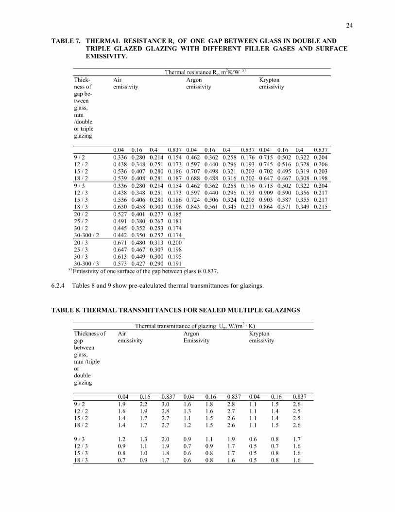
24
TABLE 7. THERMAL RESISTANCE Rs OF ONE GAP BETWEEN GLASS IN DOUBLE AND TRIPLE GLAZED GLAZING WITH DIFFERENT FILLER GASES AND SURFACE EMISSIVITY.
Thermal resistance Rs, m2K/W x)
Thick-ness of gap be-tween glass, mm /double or triple glazing
Air emissivity
Argon emissivity
Krypton emissivity
0.04 0.16 0.4 0.837 0.04 0.16 0.4 0.837 0.04 0.16 0.4 0.837 9 / 2 0.336 0.280 0.214 0.154 0.462 0.362 0.258 0.176 0.715 0.502 0.322 0.204 12 / 2 0.438 0.348 0.251 0.173 0.597 0.440 0.296 0.193 0.745 0.516 0.328 0.206 15 / 2 0.536 0.407 0.280 0.186 0.707 0.498 0.321 0.203 0.702 0.495 0.319 0.203 18 / 2 0.539 0.408 0.281 0.187 0.688 0.488 0.316 0.202 0.647 0.467 0.308 0.198 9 / 3 0.336 0.280 0.214 0.154 0.462 0.362 0.258 0.176 0.715 0.502 0.322 0.204 12 / 3 0.438 0.348 0.251 0.173 0.597 0.440 0.296 0.193 0.909 0.590 0.356 0.217 15 / 3 0.536 0.406 0.280 0.186 0.724 0.506 0.324 0.205 0.903 0.587 0.355 0.217 18 / 3 0.630 0.458 0.303 0.196 0.843 0.561 0.345 0.213 0.864 0.571 0.349 0.215 20 / 2 0.527 0.401 0.277 0.185 25 / 2 0.491 0.380 0.267 0.181 30 / 2 0.445 0.352 0.253 0.174 30-300 / 2 0.442 0.350 0.252 0.174 20 / 3 0.671 0.480 0.313 0.200 25 / 3 0.647 0.467 0.307 0.198 30 / 3 0.613 0.449 0.300 0.195 30-300 / 3 0.573 0.427 0.290 0.191
x) Emissivity of one surface of the gap between glass is 0.837. 6.2.4 Tables 8 and 9 show pre-calculated thermal transmittances for glazings. TABLE 8. THERMAL TRANSMITTANCES FOR SEALED MULTIPLE GLAZINGS
Thermal transmittance of glazing Ug, W/(m2 · K) Thickness of gap between glass, mm /triple or double glazing
Air emissivity
Argon Emissivity
Krypton emissivity
0.04 0.16 0.837 0.04 0.16 0.837 0.04 0.16 0.837 9 / 2 1.9 2.2 3.0 1.6 1.8 2.8 1.1 1.5 2.6 12 / 2 1.6 1.9 2.8 1.3 1.6 2.7 1.1 1.4 2.5 15 / 2 1.4 1.7 2.7 1.1 1.5 2.6 1.1 1.4 2.5 18 / 2 1.4 1.7 2.7 1.2 1.5 2.6 1.1 1.5 2.6 9 / 3 1.2 1.3 2.0 0.9 1.1 1.9 0.6 0.8 1.7 12 / 3 0.9 1.1 1.9 0.7 0.9 1.7 0.5 0.7 1.6 15 / 3 0.8 1.0 1.8 0.6 0.8 1.7 0.5 0.8 1.6 18 / 3 0.7 0.9 1.7 0.6 0.8 1.6 0.5 0.8 1.6

25
TABLE 9. THERMAL TRANSMITTANCES FOR GLAZINGS OF COMPOSITE WINDOWS WITH A SINGLE GLASS PANE AND A SEALED 2-GLASS UNIT
Thickness of Thermal transmittance for glazing, Ug, W/(m2 · K) gap between glass, mm Douple glazed unit /
Air emissivity
Argon emissivity
Krypton emissivity
Separate glass 0.04 0.16 0.4 0.837 0.04 0.16 0.4 0.837 0.04 0.16 0.4 0.8379 / 20-125 1.4 1.5 1.7 1.9 1.2 1.3 1.6 1.8 0.9 1.1 1.4 1.7 12 / 20-125 1.2 1.4 1.6 1.8 1.0 1.2 1.5 1.8 0.9 1.1 1.4 1.7 15 / 20-125 1.1 1.3 1.5 1.8 0.9 1.1 1.4 1.7 0.9 1.1 1.4 1.7 18 / 20-125 1.0 1.2 1.5 1.8 0.9 1.1 1.4 1.7 0.9 1.1 1.4 1.7
Explanation A composite window refers to a window with a glazing which has both
sealed multiple glazed units and separate glass. 6.3 Thermal transmittance for window frame 6.3.1 Thermal transmittance for a conventional timber window frame (Uf) is calculated using the formula (8).
1 Uf = ──────────────── (8)
β ⋅ d Rsi + Rse + ──────
λn d mean thickness of frame and casement parts, m λn normative thermal conductivity of frame and casement material β correction coefficient which takes into account the 2- or 3-dimensional heat flow in reality,
0.7 Rsi + Rse sum of surface resistances (table 2). 6.4 Thermal interaction of the frame structure and glazing 6.4.1 The increased heat loss, characteristic to the junction of glazing and the frame structure on the edges of
glazing is taken into account as a linear additional conductance (ψg) of a junction structure. Unless more detailed calculations are carried out, the values in table 10 may be used as the values for linear addi-tional conductance due to a metal edge strip of sealed glass. The value of linear additional conductance of the junction of separate glass installed in a timber or plastic casement is 0 W/(m ⋅ K).

26
TABLE 10. LINEAR ADDITIONAL CONDUCTANCE Ψg DUE TO METAL EDGE STRIP OF SEALED GLAZING UNIT
Additional conductance Ψg, W/(m ⋅ K)
Frame material Double or triple glazing, no low emissivity coating, gas or air gap
Triple glazing, low emis-sivity coating in the other gap
Double glazing with low emissivity coating, triple glazing with two low emissivity coatings, gas or air gap
Wood or plastic 0.04 0.05 0.06 Metal frame with thermal break
0.06 - 0.08
Metal frame without thermal break
0 - 0.02
6.5 Mean thermal transmittance for window 6.5.1 Mean thermal transmittance for window (Uw) is calculated using formula (9). The numerical value ob-
tained is indicated with two significant figures. Ag Ug + Af Uf + lg ψg Uw = ────────────── (9) Ag + Af Ag area of the glazing, m2 Ug thermal transmittance for the glazing, W/(m2 ⋅ K) Af projected area of the frame and casement part on the glazing level of the window, m2. Uf thermal transmittance for the frame and casement part, W/(m2 ⋅ K) lg length of linear thermal bridge formed on the edge of the opening, m ψg linear additional conductance on the edge of the glazing, W/(m ⋅ K). 6.6 Thermal transmittance for door and ventilation panel 6.6.1 Mean thermal transmittance (Up) for the opaque part of a door panel and for the opening part of a venti-
lation panel is calculated in accordance with items 2.2 and 2.3. If the same door opening has two door panels and an air gap between them, the value in accordance with table 3 is used as thermal resistance of the air gap. In this case a seal in the gap between at least one door panel and the frame is required.
6.6.2 Thermal transmittance (Uf) for the frame part is calculated in accordance with item 6.3. Thermal trans-
mittance for the possible window glazing in a door is calculated in accordance with item 6.2. Linear ad-ditional conductance for the edges of the glazing in the door panel is calculated in accordance with item 6.4.
6.6.3 If the same door opening has two door panels with windows, the windows are regarded as one window
structure in the calculations and the value in accordance with table 3 is used as thermal resistance of the air gap between them provided that at least one door panel is provided with seals.
6.6.4 If the opaque part of a door panel or the ventilation panel has thermal bridges, the effect of linear and
point thermal bridges is taken into account in the mean thermal transmittance (Up) for the opaque part and the ventilation panel in accordance with item 2.3.
6.6.5 Mean thermal transmittance (UD) for a door and ventilation panel is calculated using the formula (10).

27
Ag Ug + Ap Up + Af Uf + lg ψg UD = ──────────────────── (10) Ag + Ap + Af Ag area of a glazing, m2 Ug U-value for a glazing, W/(m2 ⋅ K) Ap area of the opaque part of a door panel, m2 Up mean thermal transmittance for the opaque part of a door panel, W/(m2 ⋅ K) Af projected area of the frame to the door panel level, m2 Uf thermal transmittance for the frame, W/(m2 ⋅ K) lg length of the linear thermal bridge formed on the edge of a glazing, m ψg linear additional conductance on the edge of a glazing, W/(m ⋅ K)