C3 Corvette - Custom FedBizOpps Postings...
13
C3 Corvette Headlight Vacuum System Functional Diagrams & Components Updated: June 28, 2011 (Update log on last page) The purpose of this paper is to illustrate the NORMAL functions and associated vacuum and atmospheric pressure states of the vacuum operated headlight extension and retraction system in C3 Corvettes. A brief troubleshooting guide, a hose connections diagram, and links to relay and repair procedures are included. Copyright © 2011, Business Data Services, All Rights Reserved
Transcript of C3 Corvette - Custom FedBizOpps Postings...
C3 Corvette
Headlight Vacuum System Functional Diagrams & Components
Updated: June 28, 2011 (Update log on last page)
The purpose of this paper is to illustrate the NORMAL functions and associated vacuum and atmospheric pressure states of the vacuum operated headlight extension and retraction system in C3 Corvettes. A brief troubleshooting guide, a hose connections diagram, and links to relay and repair procedures are included.
Copyright © 2011, Business Data Services, All Rights Reserved
2
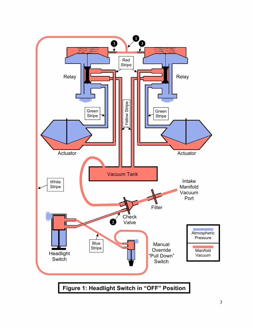
Figure 1: Shows the system state after engine start (and vacuum has accumulated) with headlight switch “OFF” and Manual Override “Pull Down” Switch in the “UP” position. Note that in the relays, vacuum “pulls” the diaphragms and dog bone valves upward against the springs. This action ports vacuum from the tank to the rear of each actuator. Thus our headlights are, in fact, held down by vacuum (or pushed down by atmos-pheric pressure) when our headlights are switched off.
3
Intake Manifold Vacuum Port
Headlight Switch
Manual Override “Pull Down” Switch
Check Valve
Filter
Vacuum Tank
Actuator Actuator
Relay Relay
Figure 1: Headlight Switch in “OFF” Position
Atmospheric Pressure
Manifold Vacuum
Yellow Stripe
Red Stripe
Green Stripe
White Stripe
Blue Stripe
Green Stripe
1
2
3 3
4
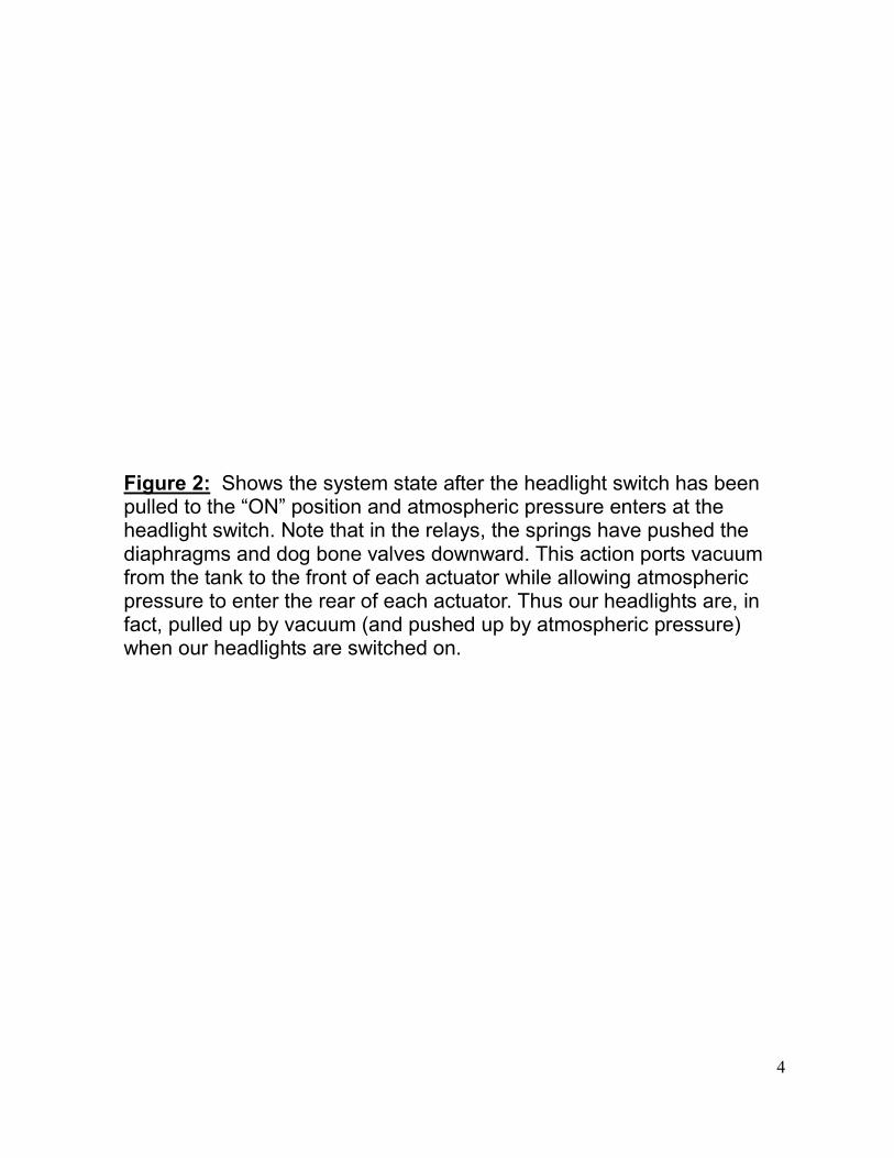
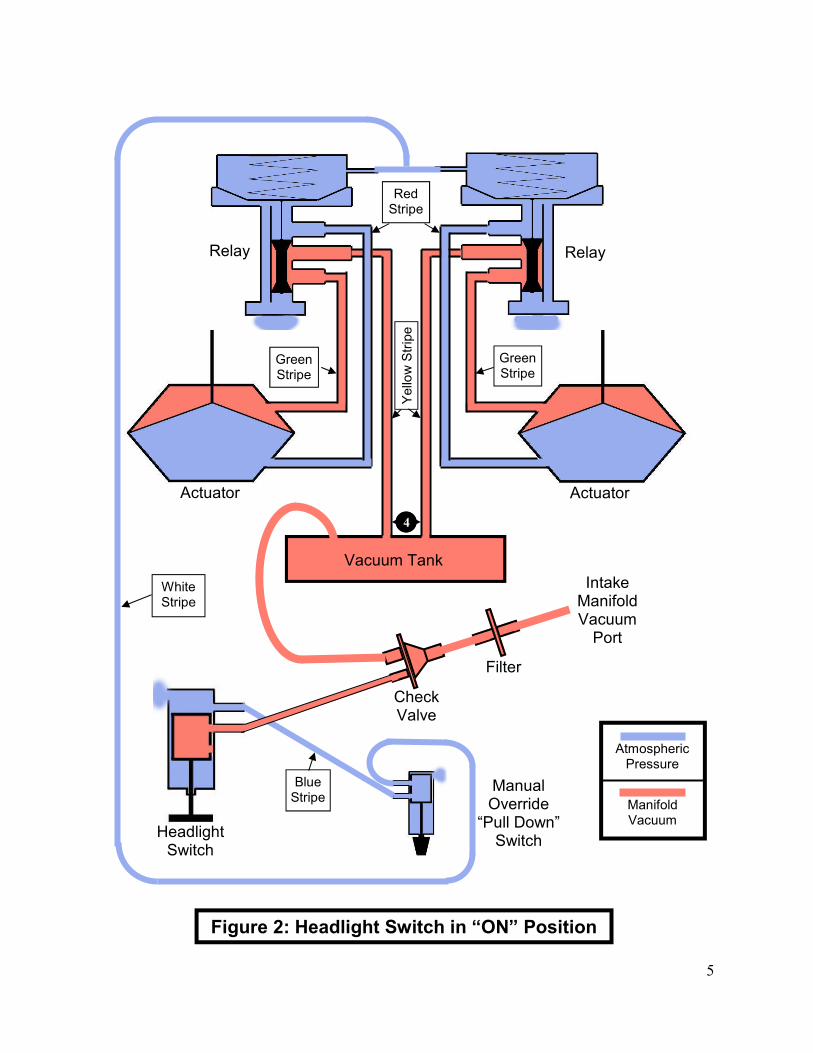
Figure 2: Shows the system state after the headlight switch has been pulled to the “ON” position and atmospheric pressure enters at the headlight switch. Note that in the relays, the springs have pushed the diaphragms and dog bone valves downward. This action ports vacuum from the tank to the front of each actuator while allowing atmospheric pressure to enter the rear of each actuator. Thus our headlights are, in fact, pulled up by vacuum (and pushed up by atmospheric pressure) when our headlights are switched on.
5
Intake Manifold Vacuum Port
Headlight Switch
Manual Override “Pull Down” Switch
Check Valve
Filter
Vacuum Tank
Actuator
Relay Relay
Figure 2: Headlight Switch in “ON” Position
Actuator
Atmospheric Pressure
Manifold Vacuum
Red Stripe
Green Stripe
White Stripe
Blue Stripe
Green Stripe
Yellow Stripe
4
6
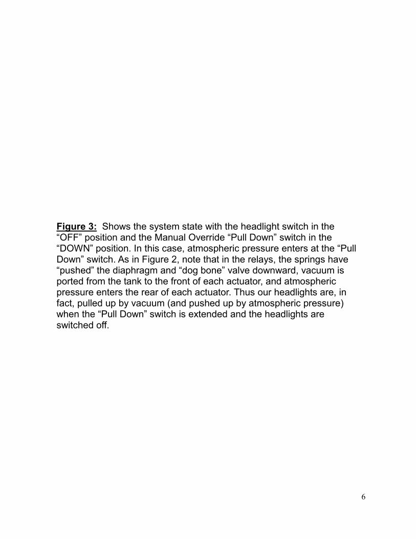
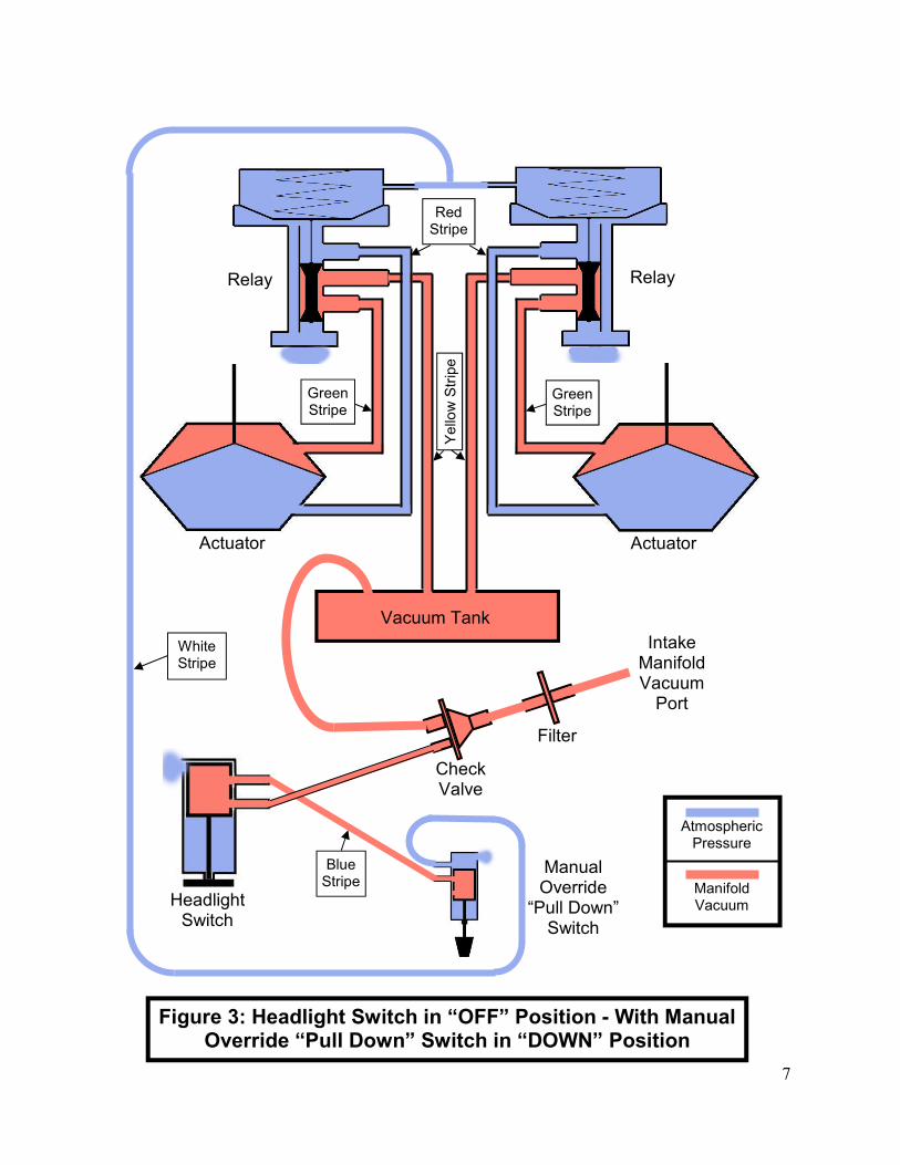
Figure 3: Shows the system state with the headlight switch in the “OFF” position and the Manual Override “Pull Down” switch in the “DOWN” position. In this case, atmospheric pressure enters at the “Pull Down” switch. As in Figure 2, note that in the relays, the springs have “pushed” the diaphragm and “dog bone” valve downward, vacuum is ported from the tank to the front of each actuator, and atmospheric pressure enters the rear of each actuator. Thus our headlights are, in fact, pulled up by vacuum (and pushed up by atmospheric pressure) when the “Pull Down” switch is extended and the headlights are switched off.
7
Intake Manifold Vacuum Port
Headlight Switch
Manual Override “Pull Down” Switch
Check Valve
Filter
Vacuum Tank
Actuator
Relay Relay
Figure 3: Headlight Switch in “OFF” Position - With Manual Override “Pull Down” Switch in “DOWN” Position
Actuator
Atmospheric Pressure
Manifold Vacuum
Yellow Stripe
Red Stripe
Green Stripe
White Stripe
Blue Stripe
Green Stripe
8
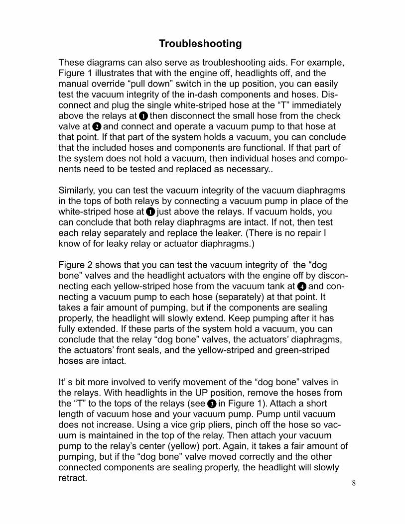
Troubleshooting
These diagrams can also serve as troubleshooting aids. For example, Figure 1 illustrates that with the engine off, headlights off, and the manual override “pull down” switch in the up position, you can easily test the vacuum integrity of the in-dash components and hoses. Dis-connect and plug the single white-striped hose at the “T” immediately above the relays at then disconnect the small hose from the check valve at and connect and operate a vacuum pump to that hose at that point. If that part of the system holds a vacuum, you can conclude that the included hoses and components are functional. If that part of the system does not hold a vacuum, then individual hoses and compo-nents need to be tested and replaced as necessary.. Similarly, you can test the vacuum integrity of the vacuum diaphragms in the tops of both relays by connecting a vacuum pump in place of the white-striped hose at just above the relays. If vacuum holds, you can conclude that both relay diaphragms are intact. If not, then test each relay separately and replace the leaker. (There is no repair I know of for leaky relay or actuator diaphragms.) Figure 2 shows that you can test the vacuum integrity of the “dog bone” valves and the headlight actuators with the engine off by discon-necting each yellow-striped hose from the vacuum tank at and con-necting a vacuum pump to each hose (separately) at that point. It takes a fair amount of pumping, but if the components are sealing properly, the headlight will slowly extend. Keep pumping after it has fully extended. If these parts of the system hold a vacuum, you can conclude that the relay “dog bone” valves, the actuators’ diaphragms, the actuators’ front seals, and the yellow-striped and green-striped hoses are intact. It’ s bit more involved to verify movement of the “dog bone” valves in the relays. With headlights in the UP position, remove the hoses from the “T” to the tops of the relays (see in Figure 1). Attach a short length of vacuum hose and your vacuum pump. Pump until vacuum does not increase. Using a vice grip pliers, pinch off the hose so vac-uum is maintained in the top of the relay. Then attach your vacuum pump to the relay’s center (yellow) port. Again, it takes a fair amount of pumping, but if the “dog bone” valve moved correctly and the other connected components are sealing properly, the headlight will slowly retract.
1
2
1
4
3
9
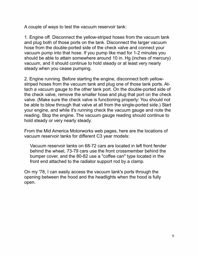
A couple of ways to test the vacuum reservoir tank: 1. Engine off. Disconnect the yellow-striped hoses from the vacuum tank and plug both of those ports on the tank. Disconnect the larger vacuum hose from the double-ported side of the check valve and connect your vacuum pump into that hose. If you pump like mad for 1-2 minutes you should be able to attain somewhere around 10 in. Hg (inches of mercury) vacuum, and it should continue to hold steady or at least very nearly steady when you cease pumping. 2. Engine running. Before starting the engine, disconnect both yellow-striped hoses from the vacuum tank and plug one of those tank ports. At-tach a vacuum gauge to the other tank port. On the double-ported side of the check valve, remove the smaller hose and plug that port on the check valve. (Make sure the check valve is functioning properly: You should not be able to blow through that valve at all from the single-ported side.) Start your engine, and while it's running check the vacuum gauge and note the reading. Stop the engine. The vacuum gauge reading should continue to hold steady or very nearly steady. From the Mid America Motorworks web pages, here are the locations of vacuum reservoir tanks for different C3 year models:
Vacuum reservoir tanks on 68-72 cars are located in left front fender behind the wheel, 73-79 cars use the front crossmember behind the bumper cover, and the 80-82 use a "coffee can" type located in the front end attached to the radiator support rod by a clamp.
On my '78, I can easily access the vacuum tank's ports through the opening between the hood and the headlights when the hood is fully open.
10
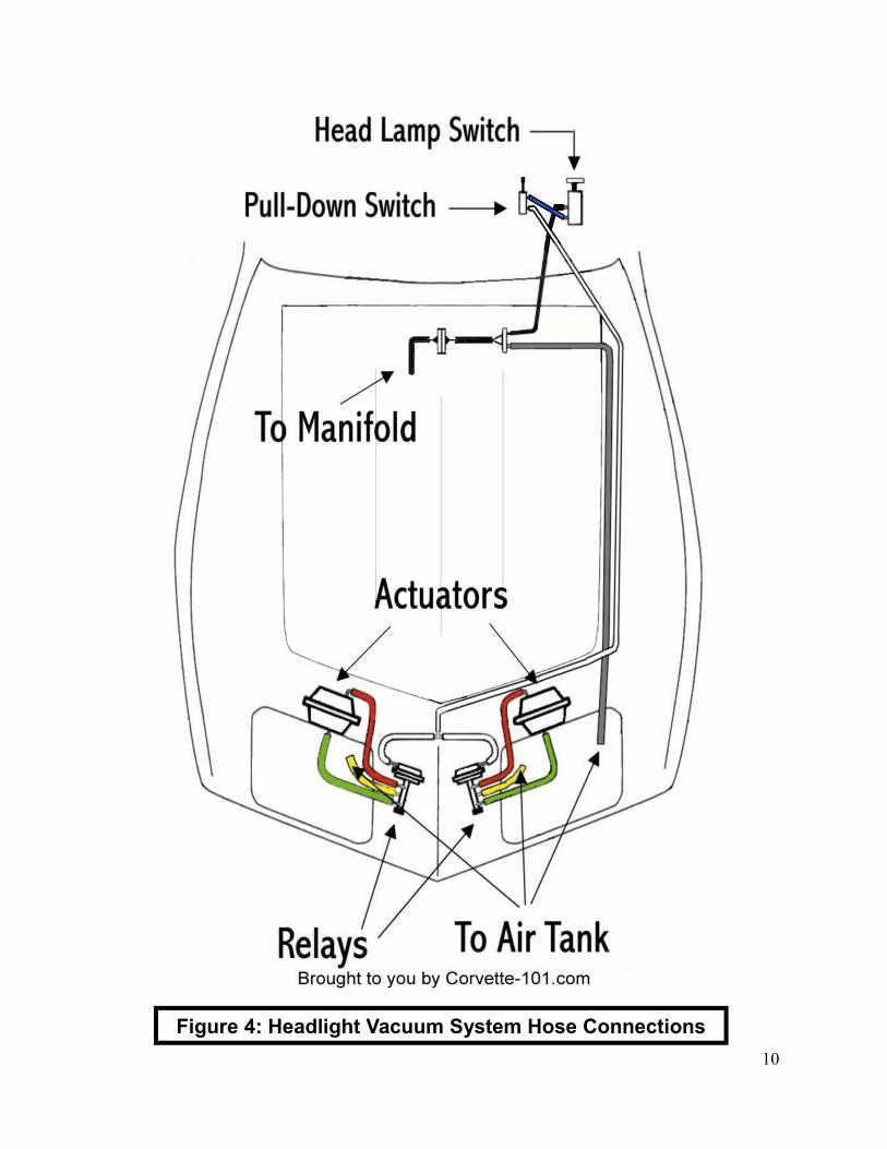
Figure 4: Headlight Vacuum System Hose Connections
11
An excellent guide for troubleshooting and testing individual headlight vacuum system components is located on Corvette-101.com *. The ex-cellent system hose connection diagram from that web site is shown in Figure 4. Corvette-101.com includes a relay repair procedure for the “dog bone” valves. Another repair method I used successfully for these valves can be found HERE *. The Willcox Corvette web site has good diagrams and photos of vac-uum components and hose connections in a .pdf file located HERE *. You'll find a good corvettemagazine.com article with lots of photos and narrative showing how to remove the actuators and replace their seals HERE. From the hard-knocks school a final tip: If your headlight vacuum sys-tem functions properly EXCEPT that one or both headlights pop up when you are heavy on the throttle for a long period, you should sus-pect the check valve. Our ‘Vette was doing that quite faithfully as we climbed our local mountain passes. When everything else checked out OK, I pulled the check valve. When I could easily blow air through it from the single port (manifold vacuum) side, I knew it was bad. All’s well since I replaced it. ———————————————————————————————- * If you click on these links and find they don’t work, here they are: Corvette-101 Vacuum pages - http://www.corvette-101.com/vacuum.htm “Dog Bone” relay valve repair - http://forums.corvetteforum.com/c3-tech-performance/1968120-vacuum-relay-valves.html Willcox Corvette Headlamp Vacuum Hose Schematics http://willcoxcorvette.com/instructions/Headlamp_Vacuum_Hose_Schematics_68-82_updated_080509.pdf Headlight actuator removal and repair procedure:

12
http://www.corvettemagazine.com/body/corvette-headlight-repair-make-them-both-open.html (Just cut & paste ‘em in your web browser’s URL address bar.)
13
Update Log
December 6, 2010: Original Issue December 11, 2010: Added Vacuum Reservoir Tank test methods and tank locations description, added link to Willcox Corvette “Headlamp Vacuum Hose Schematics 68-82”. January 9, 2011: Added link to Corvette Magazine web site article on re-moval and repair of C3 headlight actuators. January 10, 2011: Changed link to a correct Corvette Magazine web site article on removal and repair of C3 headlight actuators. February, 17, 2011: Changed reference to the vacuum hose connection diagram on the Corvette-101.com web site to reflect that the diagram posted there has been corrected. It is now the same as shown on page 10 of this document. March 8, 2011: Added Copyright © notice on cover page. June 28, 2011: Added atmospheric pressure (little blue clouds) at ports on relays, headlight switch, and bypass “pull down” switch to clarify locations and functions of these openings.