Installation Instructions for: CORVETTE SUPERCHARGER ... · PDF fileInstallation Instructions...
60
Installation Instructions for: CORVETTE SUPERCHARGER SYSTEM 2005-2007 C6 LS2 CORVETTE Step-by-step instructions for installing the best in supercharger systems. ATTENTION! Your MAGNUSON SUPERCHARGER kit is sensitive to corrosion! Take care of if by using 50/50 anti-freeze with de-ionized water. * PREMIUM FUEL REQUIRED * * PREMIUM FUEL REQUIRED *
-
Upload
nguyenhanh -
Category
Documents
-
view
237 -
download
3
Transcript of Installation Instructions for: CORVETTE SUPERCHARGER ... · PDF fileInstallation Instructions...

Installation Instructions for:CORVETTE SUPERCHARGER SYSTEM
2005-2007 C6 LS2 CORVETTE
Step-by-step instructions for installing the best in supercharger systems.
ATTENTION!Your MAGNUSON SUPERCHARGER kit
is sensitive to corrosion! Take care of if by using 50/50
anti-freeze with de-ionized water.
* PREMIUM FUEL REQUIRED ** PREMIUM FUEL REQUIRED *

SUPERCHARGER INSTALLATION MANUALMagnuson Products SuperCharger KitGM 6.0 Liter Engine2005-2007 C6 Corvette LS2
Please take a few moments to review this manual thoroughly before you begin work:
A quick parts check to make certain your kit is complete (see shipper parts list in this manual). If you discover shipping damage or shortage, please call our offi ce immediately. Take a look at ex-actly what you are going to need in terms of tools, time, and experience.Review our limited warranty with care.When unpacking the supercharger kit DO NOT lift the supercharger assembly by the black plastic bypass actuator. This is pre-set from the factory and can be altered if used as a lifting point!Caution: Relieve the fuel system pressure before servicing fuel system components in order to reduce the risk of fi re and personal injury. After relieving the system pressure, a small amount of fuel may be released when servicing the fuel lines or connections. In order to reduce the risk of personal injury, cover the regulator and fuel line fi tting with a shop towel before disconnecting. This will catch any fuel that may leak out. Place the towel in an approved container when the job is complete.
Use only premium fuel, 91 octane or better.Use only premium fuel, 91 octane or better.Magnuson Products SuperCharger systems are manufactured to produce about 20 RWHP per pound of boost at sea level. High altitudes will produce different numbers.
Our Magnuson SuperCharger kits are designed for engines in good mechanical condition only. Instal-lation on high mileage or damaged engines is not recommended and may result in engine failure, in which we are not responsible. Magnuson Products LLC is not responsible for the engine or conse-quential damages.
Magnuson Products supercharger kits are designed for use on stock vehicles. To that end, the al-Magnuson Products supercharger kits are designed for use on stock vehicles. To that end, the al-teration or modifi cation of the fuel system, drive train, engine, and/or supercharger outside of stock teration or modifi cation of the fuel system, drive train, engine, and/or supercharger outside of stock parameters in any way can result in engine damage or failure for which Magnuson Products is NOT parameters in any way can result in engine damage or failure for which Magnuson Products is NOT responsible and will void Magnuson Products warranty and CARB certifi cation. Aftermarket engine responsible and will void Magnuson Products warranty and CARB certifi cation. Aftermarket engine recalibration devices that modify fuel and spark curve (including, but not limited to programmers) are recalibration devices that modify fuel and spark curve (including, but not limited to programmers) are not recommended and may cause engine damage or failure Use of non-Magnuson Products approved not recommended and may cause engine damage or failure. Use of non-Magnuson Products approved programming will void all warrantiesprogramming will void all warranties.
A new GM fuel fi lter is recommended at the time of supercharger installation.Stock spark plugs and stock plug gap is recommendedDrives belt = Gates #K061058Air Filter = K&N #33-2111

Tools RequiredMetric wrench set1/4” - 3/8” and 1/2” drive metric socket set (standard & deep)3/8” and 1/2” drive Foot pound and inch pound torque wrenchesBelt tensioner wrenchPhillips and fl at head screwdrivers1/2” breaker barFuel line quick disconnect tools (included in kit)Small or angles 3/8 drill motorDrain panHose cuttersHose clamp pliersSafety glassesTorque angle meter1/2” impact gunSmall drift punchHammerHarmonic balancer modifi cation kit (included in kit)Compressed airBlow gunMetric Allen socket set 3/8 driveMetric Torque socket set 3/8 drive18mm metric line wrenchPower steering oil suction tool or turkey baster.
Magna Charger has joint ventured with RK Sports, Lingenfelter Performance Engineering, and Ken Grody Performance in the development of aftermarket hoods that will clear the supercharger system. It is our goal to add all new hood suppliers to the list as they become available.

Stock ClipStock Clip
Hood BoltsHood Bolts
1. Raise the vehicle on a automotive hoist using the factory recommended lift points. Refer to the owners manual or shop guide for these locations.
2. Remove the stock hood by disconnecting the hood lamp electrical connector, un-clipping the small gas charged hood shocks and removing the four bolts with a 13mm socket wrench. The stock hood will NOT be reused. Contact Magnuson for recommended hood solutions.
3. With a cool engine drain the coolant into a clean drain pan for reuse later. Remove the ra-diator cap to vent the system. (Be careful not to remove the radiator cap if the engine is still hot.)
4. With a 10mm wrench disconnect the (-) nega-tive battery cable. Make sure the cable is far enough away from the battery that it does not ac-cidentally touch the battery and make connection during the installation.
NegativeNegative

6. Remove the six push-lock fasteners securing the rear splash panel.
5. Remove the front right wheel with a 17mm wrench.
7. Remove the Push-lock fasteners by gently prying up on the center of the fastener and then removing the fastener completely.
8. Remove the bolts that secure the bottom of the splash panel using a 10mm socket wrench.
Remove 6 Remove 6 Push-lock Push-lock fastenersfasteners
Push-lock Push-lock fastenerfastener

9. Removing the inner fender panel will expose the vehicles operating computer.
10. There are three computer connectors, Grey, Black, and Blue. Remove the connectors by fi rst removing the Red locking key, then pushing in on the Black cover and pushing the Grey latch down.
11. Remove the computer connectors carefully by pulling straight out.
12. Note: If your vehicle has a automatic trans-mission, you will also need to remove the trans-mission control computer located on the back side of the mounting bracket.
LatchedLatched
KeyKeyLatchLatch
UnlatchedUnlatched
RemoveRemove
Mounting Mounting bracketbracket

13. Here are the shipping materials supplied to quickly return the vehicle computers to Magnuson Products Inc.
14. Place the computers into the plastic bag sup-plied and then wrap it in the packing sheet and seal the box.
15. Completely fi ll out the pre-paid shipping form supplied and then remove the adhesive label on the third page, placing it on the top of the box. Take the box to your nearest UPS offi ce to be re-turned to Magnuson Products Inc. Magnuson will then re-program the computer and quickly return it to you via UPS.
16. Remove the pressure in the fuel tank by re-moving and then replacing the fuel fi ller cap.

17. Remove the engine oil fi ller cap, then remove the engine/coil covers by pulling up fi rmly on them. The covers will not be reused.
18. Replace the engine oil fi ller cap.
19. Remove the Mass Air Flow meter (MAF) connector by pulling up on the grey release trig-ger and squeezing the connector.
20. Remove the PCV inlet tube from the air fi lter bellows by pushing up on the release lever. Next pull the tube free from the valve cover barb. The tube will not be reused.
Push to releasePush to release

21. Remove the air fi lter cover by pulling out on the ends and lifting the cover free.
22. Remove the air fi lter hood clips on both air fi lter elements .
23. Remove both air fi lter elements and hoods.
24. Loosen the air fi lter bellows clamp with a 6mm nut driver or a straight blade screwdriver.
Pull OutPull Out

25. Lift straight up on the plastic air tube to de-tach it from the two locating pegs.
26. Remove the air fi lter assembly complete with the MAF and bellows from the vehicle.
27. Using a 10mm socket wrench, remove the two bolts on each side of the radiator cover.
28. Remove the radiator cover and set it aside for a modifi cation in a later step.

29. Un-clip the coolant hoses from the fan shroud.
30. Use a small straight blade screwdriver to open the two harness clamps and release the wiring harness on the fan shroud.
31. Locate the cooling fans electrical connec-tor under the wiring harness located on the fan shroud. Squeeze the connector fi rmly and pull the connector free as shown.
32. The fan shroud is held to the radiator by two bolts located near the bottom of the radiator on the drivers side (shown) and near the top on the passenger side. Remove the two bolts with a 10mm socket wrench. The fan and shroud as-sembly will be removed in a later step.
Coolant hose clipsCoolant hose clips
LatchedLatched
Fan electrical connectorFan electrical connector

33. Disconnect the EVAP intake tube on intake manifold by pushing in on the white release trig-ger and pulling the connector free.
34. Release the other end of the tube at the bot-tom of the EVAP solenoid by pushing in on the release trigger.
35. Remove the tube completely and set it aside as it will be re-used in a later step.
36. Release the vent tube at the top of the EVAP solenoid by pushing in on the release trigger.
Push in on triggerPush in on trigger
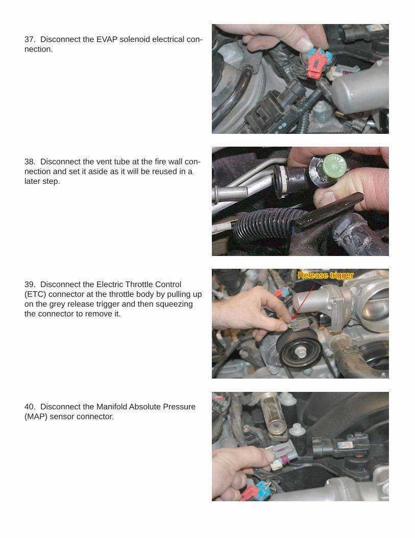
37. Disconnect the EVAP solenoid electrical con-nection.
38. Disconnect the vent tube at the fi re wall con-nection and set it aside as it will be reused in a later step.
39. Disconnect the Electric Throttle Control (ETC) connector at the throttle body by pulling up on the grey release trigger and then squeezing the connector to remove it.
40. Disconnect the Manifold Absolute Pressure (MAP) sensor connector.
Release triggerRelease trigger

41. Use a shop knife to cut the tape that secures the wiring harness to the fuel rails in four loca-tions.
42. Disconnect the eight fuel injector connectors by pressing in on the release triggers and pulling the connectors free.
43. Use a 13mm socket wrench to remove the nut that secures the battery cable on the back of the alternator.
44. Pull up on the anchors that secure the bat-tery cable to the intake manifold in two locations.

45. Free the battery cable from the intake mani-fold and lay it aside.
46. Remove the power brake check valve and hose from the brake booster grommet by pulling it out fi rmly.
47. On the passenger side of the intake manifold behind the throttle body, remove the PCV hose.
Intake BoltsIntake Bolts
48. With a 8mm socket wrench remove the ten intake manifold bolts.
Brake check valveBrake check valve

49. Carefully remove the intake manifold and set it aside.
50. Using a vacuum cleaner, remove any dirt or debris from the intake port area. (Be careful not to get any debris in the intake ports.)
51. Cover the intake manifold ports with tape or clean rags to keep dirt and objects from entering the engine.
52. From under the vehicle, remove the four bolts that secure the sway bar brackets to the chassis with a 13mm socket wrench
Sway bar bracketSway bar bracket

53. Remove the nuts that secure the sway bar end links to the lower A-arms on both sides of the vehicle. Use a 18mm socket on the outside and a 18mm open-end wrench on the inside.
54. After removing the sway bolts, brackets and end link nuts, remove the sway bar and set it aside.
55. Remove the fan assembly by pushing up on the fan shroud to Un-clip it from the radiator and then pull the assembly out from the vehicle com-pletely.
56. Using a 19mm socket wrench, loosen the four front sub-frame nuts shown.
End link nutEnd link nut
Push up then pull Push up then pull downdown
ClipClip
Sub-frame nutsSub-frame nuts

57. Loosen the four front sub-frame nuts until the bottom of the nut is even with the end of the threads on the bolt. The gap between the washer and the sub-frame should be approximately ½”.
58. Remove the two motor mount nuts with a 19mm socket wrench
59. Using a suitable pry bar, pry down the sub-frame at the front two mounting points. Tempo-rally push a metal or wooden wedge approxi-mately 3/8” thick between the frame and sub frame at these points.
60. Using a fl oor jack and a sturdy piece of wood between the jack and the bottom of the oil pan, gently raise the engine.
1/2” Gap1/2” Gap
Remove motor Remove motor mount nutsmount nuts
FrameFrame
Sub-frameSub-frame
WedgeWedge

61. When raising the engine with the fl oor jack, take care to watch the clearance between the back of the engine and the fi re wall, so as not to damage any of the components on the fi re wall.
62. Using a 17mm wrench, remove the power steering line attached to the top of the steering rack. Use a shop towel to catch any fl uid lost.
63. The following steps may be preformed from above or below on the vehicle. For clarity they are shown from below. Remove the front har-monic balancer bolt using a 24mm impact socket and a ½” impact wrench.
We recommend safety glasses during all steps. Please be sure to wear them during these steps.
64. Install the drill guide using the supplied bolt and tighten to 30 ft-lbs with a 24mm socket and torque wrench.
Watch clearanceWatch clearance

66. Using compressed air, blow the drill shavings out of the holes.
67. Install the supplied reamer into drill. Using a small amount of oil, ream holes until reamer bot-toms out in the holes.
68. Using a 24mm socket, remove the large bolt and the drill guide from the engine.
65. Using a small or angled 3/8” drill and the supplied drill bit, insert the drill into the guide holes and drill to the second step of the drill bit. (Make sure that you drill all the way to the second step.)

69. Use compressed air to blow out the holes.
70. Insert the two supplied hardened roll pins into the drilled holes. The use of a small hammer and punch may be necessary to tap the pins in. (Make sure that the pins are in far enough that they do not touch the balancer bolt.)
71. Install the new supplied factory GM harmonic balancer bolt.
72. Using a 24mm socket tighten the new har-monic balancer bolt according to General Motors specifi cations. Tighten to 50 Nm (37 ft-lbs) then tighten an additional 140 degrees using a torque angle meter.

73. With the crankshaft modifi cations complete, replace the power steering line previously re-moved and tighten the fi tting securely.
74. Replace the sway bar by installing it in its original position and replacing the sway bar brackets and reconnect the end links.
75. Reinstall the fan assembly. Use care not to damage the radiator core and clip the fan as-sembly back into place. Install the two bolts that held it into place and reconnect the fan electrical connection. Clip the wiring harness and coolant lines back into their original locations on the fan shroud.
76. Remove the wedges from between the frame and sub frame. Tighten the sub frame and motor mount nuts securely.

77. Torque the sub-frame, sway bar connections and motor mounts to the torque values below:Torque Specifi cations:
Engine sub-frame nuts 80 ft-lbsMotor mount nuts 60 ft-lbsSway bar to frame 45 ft-lbsSway bar link nuts 55 ft-lbsWheel lug nuts 110 ft-lbs
78. Remove the eight Push-lock fasteners that secure the front splash panel as shown.
79. Remove the four bolts that secure the spoiler with a 7mm socket wrench.
80. Remove the front splash panel.
Remove 8 Remove 8 Push-lock Push-lock fastenersfasteners

81. Remove the brake cooling duct, it will pull out.
82. Unbolt the horn assembly with a 13mm wrench
83. Squeeze the electrical connector on the horn assembly to disconnect it.
84. Use a 10mm wrench to remove the nut that secures the bottom edge of the nose cover.
Nose cover nutNose cover nut

85. This is the intercooler coolant pump and its mounting clamp. Note: The plastic caps on the inlet and out should be removed before the hose connections are made.
86. The pump will mount in this location beside the horn mounting point on the nose sub-frame.
87. The small panel the pump will mount on has a hole in it near the front edge. Pass the bolt for the mounting clamp through this hole.
88. Secure the clamp bolt on the bottom of the panel with the nut and washer supplied. Tighten them with a 10mm wrench
Mounting clampMounting clamp
Inter cooler coolant pumpInter cooler coolant pump
PumpPump
BoltBolt
Clamp nut and washerClamp nut and washer

89. Start the Heat exchanger installation by ap-plying the adhesive backed foam strip to the back side of the heat exchanger top and bottom tanks. The back side of the heat exchanger is the side without the two hose connections.
90. Apply a small piece of the foam strip to the Heat Exchanger Retaining Bracket.
91. Install the brass Coolant Air-bleed Valve into the top of the heat exchanger with a 11mm wrench.
92. Using a 1” hole saw, make a hole in the top of the radiator shroud on the passenger (right) side. This will create a access hole for the cool-ant air-bleed valve.
Air-bleed valveAir-bleed valve
1.00” Hole 1.00” Hole sawsaw
3.00”3.00”
1.25”1.25”
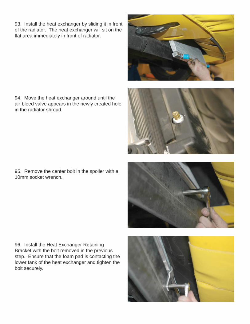
93. Install the heat exchanger by sliding it in front of the radiator. The heat exchanger will sit on the fl at area immediately in front of radiator.
94. Move the heat exchanger around until the air-bleed valve appears in the newly created hole in the radiator shroud.
95. Remove the center bolt in the spoiler with a 10mm socket wrench.
96. Install the Heat Exchanger RetainingBracket with the bolt removed in the previous step. Ensure that the foam pad is contacting the lower tank of the heat exchanger and tighten the bolt securely.

97. Using the 1” hole saw again, create one or two holes in the right hand splash panel below the radiator. This is where the coolant lines will pass through to the heat exchanger.
98. Install the intercooler cap onto the reservoir and then place the reservoir on top of the vehicle battery. Note: The locations of the inlet and outlet barbs.
99. Using the length of 3/4” hose supplied, install one end on the outlet barb of the reservoir and route it under the fuse relay center and along the frame down to the coolant pump. The complete routing of all the hose is shown.
100. Cut the hose to length and connect the hose to the inlet barb of the pump. Secure both ends of the hose with the spring clamps supplied. OutletOutlet
PumpPumpInletInlet
OutletOutletCoolant hose Coolant hose to pumpto pump
RESERVOIRRESERVOIR
OutletOutlet
InletInlet
2 X 1.00” Holes2 X 1.00” Holes
Hose to water manifoldHose to water manifold

101. Connect one end of the remaining length of hose to the pump outlet an loop it over the top of the pump. Continue the hose out through the new hole in the splash panel to the left hose barb on the bottom of the heat exchanger. Secure the hose on the pump with the spring clamp supplied.
102. Cut the hose to length and then install the 90 degree “elbow” fi tting into the end of the hose. Cut a three inch length of hose from the remain-ing hose and connect it to the elbow fi tting. Final-ly connect the 3” length to the driver side barb of the heat exchanger. Secure all connections with the spring clamps supplied.
103. On the right barb of the heat exchanger make another connection like the one in the previous step. Route the remaining hose through the hole in the splash panel and up along the frame rail to the fi re wall area. The fi nal hose connections will be made in a later step.
104. Remove the accessory serpentine belt by rotating the tensioner bolt with a 15mm wrench. Release the slack and then pull the belt off the tensioner pulley.
OutletOutlet
To heat To heat exchangerexchanger
Left barbLeft barb
3”3”
“Elbow” fi tting“Elbow” fi tting
Hose from pumpHose from pump

105. Remove the stock tensioner assembly by removing the two mounting bolts with a 15mm wrench.
106. Install the new tensioner assembly in place of the stock unit with the original bolts and torque them to 40 ft-lbs.
107. Remove the coolant hose from the vent pipe, then, remove the vent pipe with a 10mm socket wrench. Ensure that the O-ring gaskets under the vent pipe blocks do not stick to the cyl-inder heads. If so, remove them as new gaskets are supplied.
108. Install the new O-ring gaskets on the vent pipe blocks using some of the supplied lubricant to hold them in place.

109. Install the new vent pipe with the original bolts and torque them with a torque wrench and 10mm socket to 106 in-lbs
110. Remove the electrical connector from the Oil pressure sensor.
111. Use a 1-1/16” socket wrench to remove the oil pressure sensor from the engine valley cover.
112. Use a 12mm socket wrench to remove the ten bolts that secure the engine valley cover.

113. The gasket will be reused, the original valley cover will not. Inspect the gasket for any damage and then re-install, note that it will only fi t correctly in one position.
114. From the bottom of the original valley cover, remove the eight O-rings with a small straight blade screwdriver. Install the O-rings into the grooves in the bottom of the new valley cover.
115. Install the new valley cover and fl athead bolts supplied with a 5mm Allen socket and torque wrench. Torque the bolts to 15 ft-lbs. Insert the six O-rings supplied in the recesses in the valley cover.
116. Install the oil pressure sensor into the new valley cover and torque it to 22 Ft-Lbs. Re-con-nect the oil pressure connector.
O-ringsO-rings

117. Remove the upper radiator hose from the water pump housing by squeezing the spring clamp and pulling the hose free.
118. Using a power steering oil suction tool or turkey baster, remove the fl uid from the power steering (PS) reservoir and put into a disposable container. (Old fl uid can be disposed of an a oil recycling center.)
119. Using a 15mm wrench, remove the two bolts that secure the PS fl uid reservoir to the alternator bracket.
120. Remove the mounting bracket from the res-ervoir then remove the large hose from the bot-tom of the PS reservoir by squeezing the clamp with a pair of pliers. Use a shop towel to catch any residual fl uid.
Mounting Mounting BeltsBelts
Fluid hoseFluid hose

121. Remove the small hose from the bottom of the reservoir and set it aside for re-mounting in a later step.
122. Using the length of 5/8” hose supplied, install the hose connector in the end of it and secure it with the #10 clamp supplied.
123. Install the 5/8” hose with the connector into the end of the large PS hose to the pump. Se-cure the connector with the original spring clamp.
124. Pass the 5/8’ PS hose through the center of the new serpentine drive belt.
Hose connectorHose connector
Hose connectorHose connector
5/8” hose5/8” hose

125. Re-install the mounting bolts back into the alternator bracket and tighten to 50 Nm (37 ft-lbs).
126. Remove the wiring harness anchor from the front of the right (passenger side) cylinder head.
127. Install the new PS reservoir mounting bracket using the new bolts supplied. Tighten the bolts securely and torque them with a 15mm socket and torque wrench.
128. Connect the length of 3/8” hose to the smaller barb on the bottom of the PS reservoir. Secure the hose with the #4 clamp supplied.
Mounting BoltsMounting Bolts

129. Slide the PS reservoir into place on the new mounting bracket.
130. Route the 5/8” PS hose along the fan shroud, following the same path as the coolant lines.
131. Connect the 5/8” PS hose to the large barb on the bottom of the PS reservoir and secure it with a #10 clamp supplied. Replace the upper radiator hose into its original position.
132. Locate the small hose removed from the PS reservoir and follow it down to where it connects to a hard line. Cut the clamp securing the hose to the hard line and remove the hose.
5/8” PS 5/8” PS hosehose
Cut ClampCut Clamp

133. Route the new hose from the small barb on the PS reservoir along the same path as the 5/8” hose and trim it to length. Connect the hose se-curely to the hard line with the #4 clamp supplied. Using only GM recommended fl uid, fi ll the power steering reservoir to the full cold mark. (Recheck the level after start up and after turning the steer-ing wheel lock to lock a few times.)
134. Using a pair of pliers to squeeze the stock spring clamp, rotate the coolant line shown where it meets the water pump housing. Rotate the hose so that it will not contact the tensioner mounting bolt and release the clap to hold it the new position.
135. Remove the hose and clamp from the cool-ant vent “T” fi tting.
136. Connect the new 1/4” coolant hose to the coolant vent “T” fi tting with the #4 clamp supplied. Tighten the clamp securely and route the hose along the same path as the PS hoses to the barb on the coolant vent pipe. Replace the radiator cover previously removed.
Clearance between Clearance between hose and bolthose and bolt
Rotate hose hereRotate hose here
Coolant vent hoseCoolant vent hose
New hose to coolant New hose to coolant vent pipevent pipe
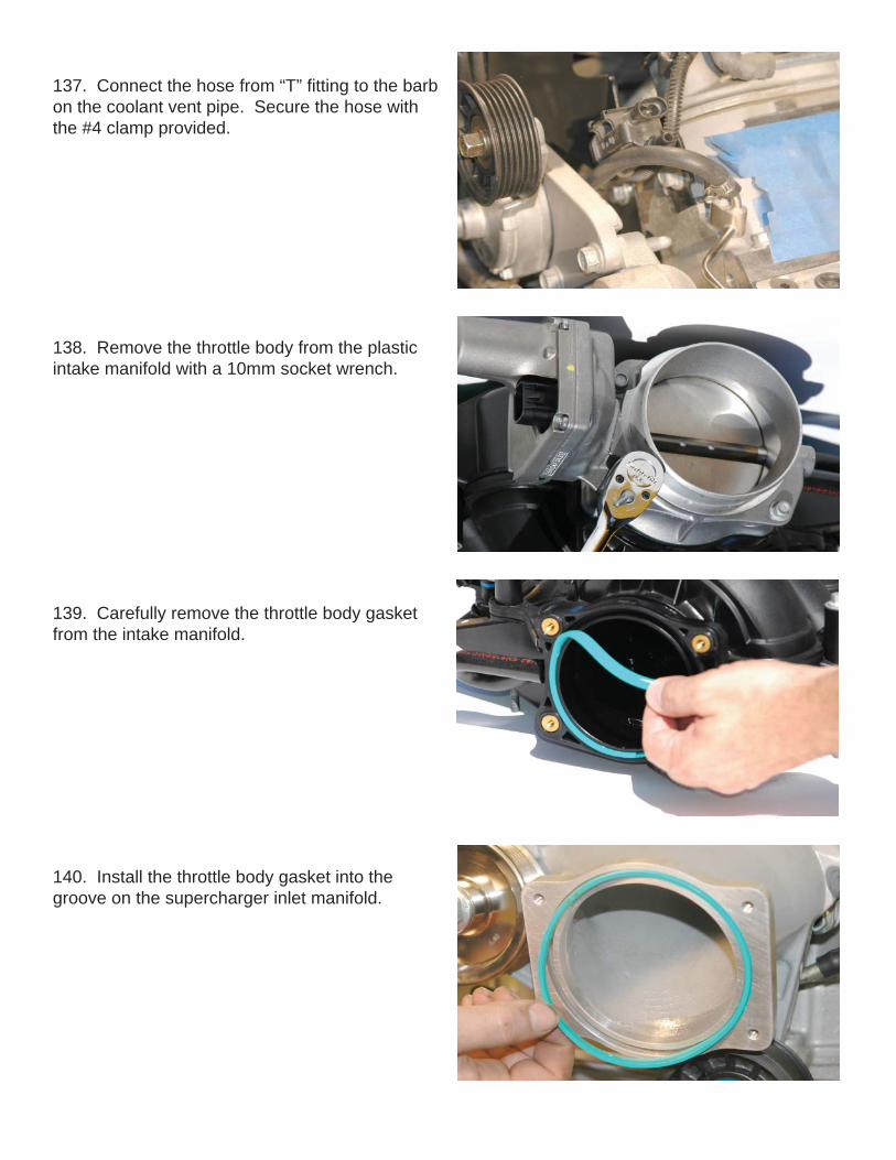
137. Connect the hose from “T” fi tting to the barb on the coolant vent pipe. Secure the hose with the #4 clamp provided.
138. Remove the throttle body from the plastic intake manifold with a 10mm socket wrench.
139. Carefully remove the throttle body gasket from the intake manifold.
140. Install the throttle body gasket into the groove on the supercharger inlet manifold.

141. Install the throttle body onto the inlet mani-fold using the original bolts. Tighten the bolts with a 10mm socket and torque wrench to 106 In-Lbs (12Nm).
142. Remove the Manifold Absolute Pressure (MAP) sensor from the stock intake manifold by tilting the sensor forward and lifting it free. En-sure that the orange rubber seal is not missing or damaged as it and the sensor will be re-used.
143. Apply a small amount of the grease sup-plied to the MAP sensor seal and install the sensor in its new location at the right rear of the supercharger manifold.
144. Install the MAP sensor in its new location using the supplied bracket and the button head Allen screw with a 4mm Allen wrench.

145. Install the two intake manifold gaskets sup-plied onto the recesses in the manifold face.
146. Install the fuel manifold O-ring into the recess on the fuel rail with some of the grease supplied.
147. Next install the fuel manifold to the fuel rail using the supplied Allen bolts. Tighten and torque the bolts with a 4mm Allen socket and torque wrench.
148. Spray silicone or some mild soap and water solution on the cylinder head surface to lubricate. This makes the intake manifold slide around a little to help line up the holes. (Do not use any-thing that will damage the intake gaskets, petro-leum based products, etc.)
Fill holesFill holes
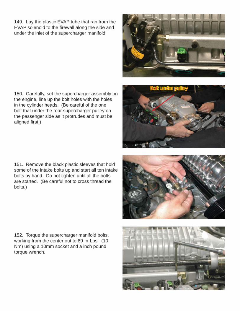
150. Carefully, set the supercharger assembly on the engine, line up the bolt holes with the holes in the cylinder heads. (Be careful of the one bolt that under the rear supercharger pulley on the passenger side as it protrudes and must be aligned fi rst.)
151. Remove the black plastic sleeves that hold some of the intake bolts up and start all ten intake bolts by hand. Do not tighten until all the bolts are started. (Be careful not to cross thread the bolts.)
152. Torque the supercharger manifold bolts, working from the center out to 89 In-Lbs. (10 Nm) using a 10mm socket and a inch pound torque wrench.
149. Lay the plastic EVAP tube that ran from the EVAP solenoid to the fi rewall along the side and under the inlet of the supercharger manifold.
Bolt under pulleyBolt under pulley

153. Install the new supplied supercharger and accessory fan belt with a 15mm tensioner wrench, using the new supplied belt routing dia-gram below.
155. Connect the hose from the heat exchanger to the driver side water manifold barb. Using the remaining length of hose, connect one end to the passenger side barb and the other end to the inlet barb on the intercooler reservoir. Secure all connections with the spring clamps supplied.
154.
Belt Routing Diagram
156. This is a plumbing diagram for the intercool-er system. Note: The fi nal connections for the intercooler will be made in a later step.
From heat From heat exchangerexchanger
To ReservoirTo Reservoir
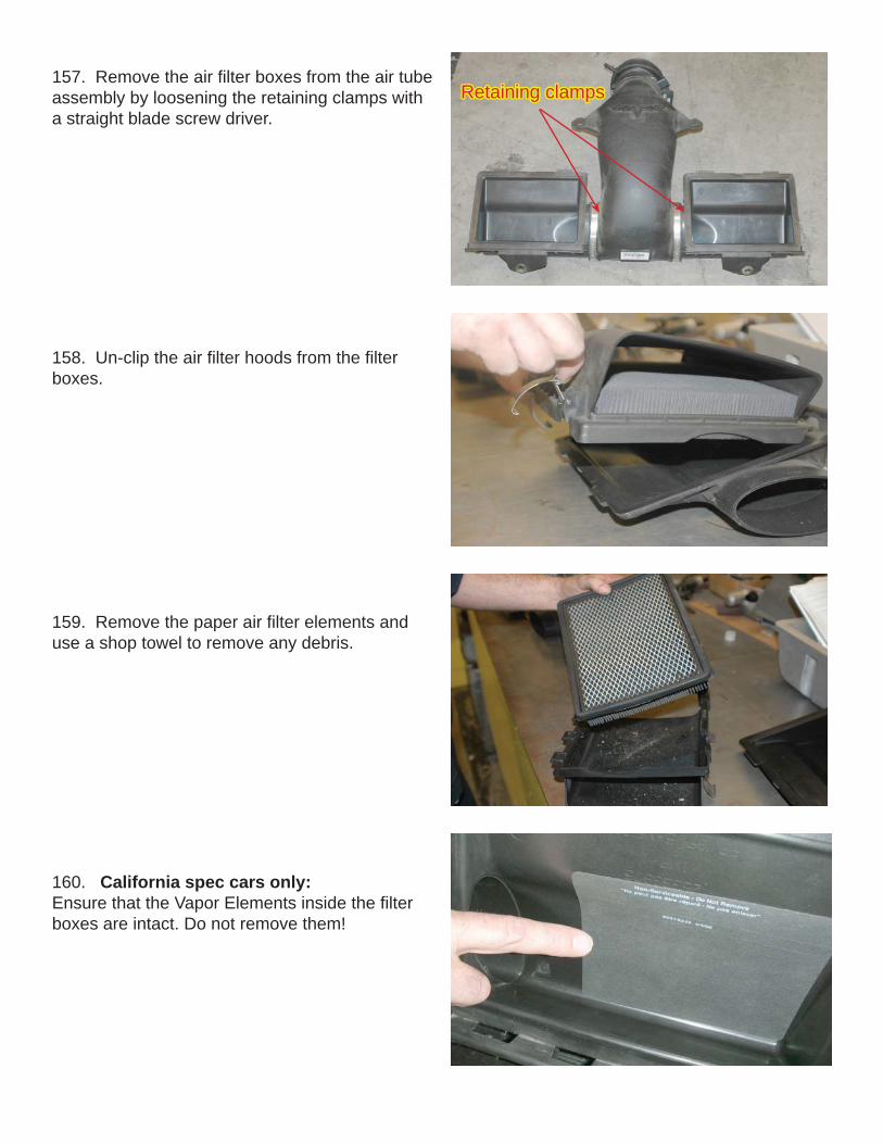
157. Remove the air fi lter boxes from the air tube assembly by loosening the retaining clamps with a straight blade screw driver.
Retaining clampsRetaining clamps
159. Remove the paper air fi lter elements and use a shop towel to remove any debris.
158. Un-clip the air fi lter hoods from the fi lter boxes.
160. California spec cars only:Ensure that the Vapor Elements inside the fi lter boxes are intact. Do not remove them!

162. Install the new air fi lter elements and re-clip the hoods onto the fi lter boxes.
163. Here is a dismantled view of the new inlet assembly. Note: The new lower air tube and gaskets.
161. California spec cars only:Re-install the paper air fi lter elements if they are clean, If they need replacement use only original GM parts (not supplied). Do not use the K&N elements supplied.
164. Install the gaskets onto the inlets of the lower air tube assembly as shown

165. Slide the air boxes into the gaskets on the lower air tube and secure them there using the original clamps.
166. Install a gasket onto the Mass Air Flow meter (MAF) and note where the “Tooth” contacts the gasket.
167. To allow the gasket to seal better around the MAF, mark then cut with a shop knife a notch in the gasket 7/16” (11mm) wide by 1/4” (6mm) deep in the inside edge using the tooth as a guide.
168. Here is the upper air tube assembly with our modifi ed gasket for the MAF. Note: You will re-use all of the original hose clamps.
GasketGasket
ToothTooth
1/4”1/4”
7/16”7/16”
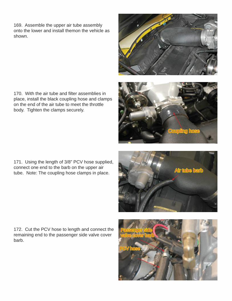
169. Assemble the upper air tube assembly onto the lower and install themon the vehicle as shown.
170. With the air tube and fi lter assemblies in place, install the black coupling hose and clamps on the end of the air tube to meet the throttle body. Tighten the clamps securely.
171. Using the length of 3/8” PCV hose supplied, connect one end to the barb on the upper air tube. Note: The coupling hose clamps in place.
Coupling hoseCoupling hose
Air tube barbAir tube barb
172. Cut the PCV hose to length and connect the remaining end to the passenger side valve cover barb.
Passenger side Passenger side valve cover barbvalve cover barb
PCV hosePCV hose

173. Locate the original EVAP line that con-nected the solenoid to the inlet manifold. Using a shop knife, cut the plastic tubing where it meets the end fi ttings.
174. Remove the end fi ttings from the plastic tubing.
175. Using a 18” length of the 5/16” hose pro-vided, insert the EVAP end fi ttings into the end of the hose and secure them with the #4 clamps provided.
176. Connect the end of the new EVAP line with the right-angle “elbow” fi tting to the lower barb of the EVAP solenoid.
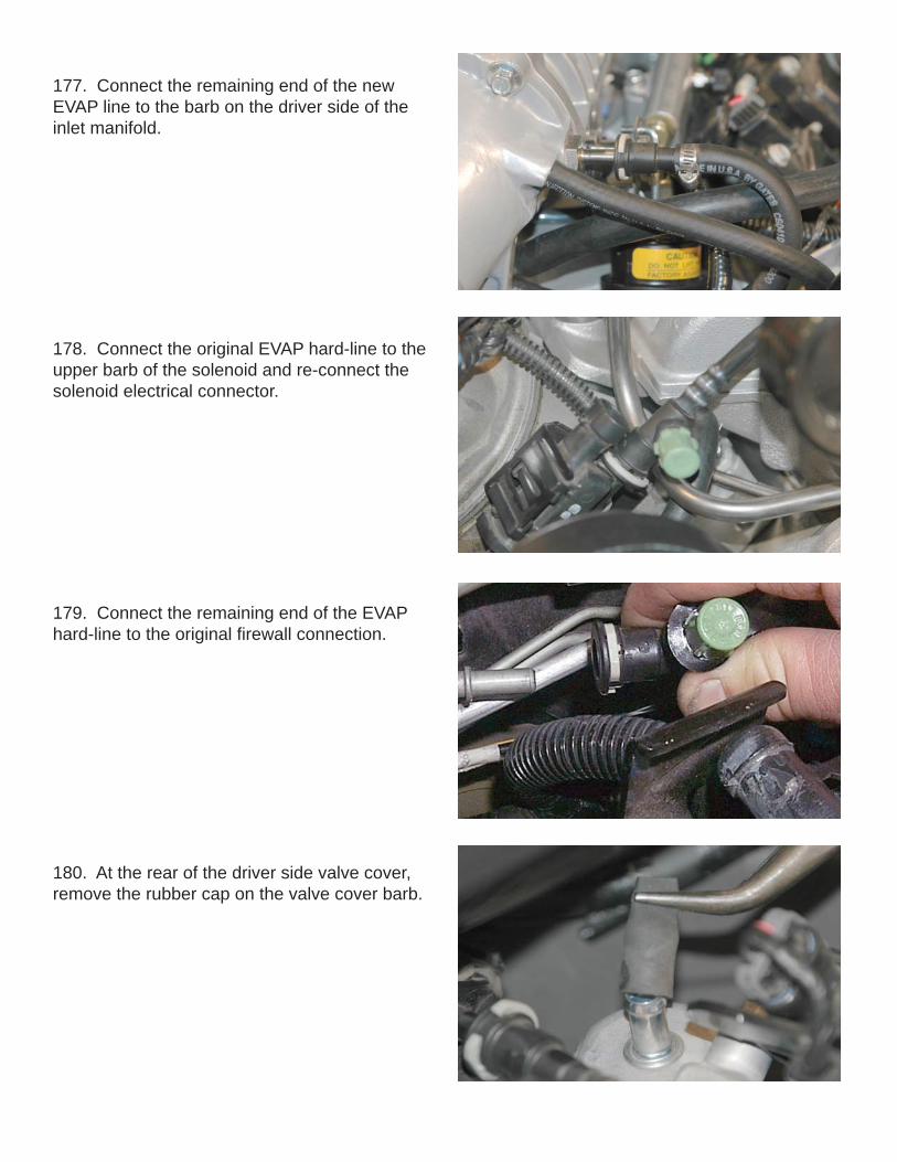
177. Connect the remaining end of the new EVAP line to the barb on the driver side of the inlet manifold.
178. Connect the original EVAP hard-line to the upper barb of the solenoid and re-connect the solenoid electrical connector.
179. Connect the remaining end of the EVAP hard-line to the original fi rewall connection.
180. At the rear of the driver side valve cover, remove the rubber cap on the valve cover barb.

181. Assemble the PCV outlet hose by cutting a 2” length and attaching one end to the 90 degree “Elbow” fi tting. Attach the other end to the barb on the driver side valve cover. From the remain-ing length cut a 38” length and connect one end to the remaining barb on the elbow fi tting. 3/8” PCV Hose3/8” PCV Hose
To PCV valveTo PCV valve
ElbowElbow
182. Connect the remaining end of the PCV hose to the 3/8” hose barb located on the bottom of the bearing support for the supercharger drive shaft.
183. Connect the vehicle fuel line to the barb on the fuel manifold by pushing it on fi rmly.
184. Secure the fuel line by re-installing the safety clip.

185. Insert the new brake vacuum check valve into the end of the 11/32” vacuum hose supplied.
186. Install the check valve and hose assembly into the grommet on the power brake booster.
187. Cut the power brake hose to length and connect the remaining end of the hose to the barb on the driver side of the inlet manifold.
Connect brake Connect brake hose herehose here
188. Here is the electrical wiring and hardware for the vehicle. On the left is the Intercooler wiring and relay. On the right is the Fuel Pump Booster with its wiring and hardware.

189. Open the Fuse/Relay center cover. Re-move the positive (B+) battery cable connections by removing the securing nut with a 12mm socket wrench. Using a 7mm socket wrench, unscrew the four captured bolts in the top of the Fuse/relay center. These bolts cannot be removed, when you can feel the bolts spinning and no longer in their threads press the bolts down as this will disconnect the four wiring blocks from the bottom of the Fuse/Relay center. Detach the fuse relay center from it’s base by gently prying open the four retaining clips. Pull up fi rmly on the fuse relay center to expose the four wiring blocks located in the base.
ClipsClips
190. The four wiring blocks are different colors, light-grey, white, dark-grey and black. Lift the DARK GREY block from the base.
191. Gently remove the wire cover from the bot-tom of the DARK GREY wiring block by prying up on the clips that retain the cover on each end. This will expose the wire connections on the bot-tom of the block.
Pry clips Pry clips upup
192. Here is the DARK GREY wiring block with the bottom cover removed showing the wiring. Note: The wire connections are lettered across the top and numbered down the side. Locate the GREY wire in the A7 location. This is the wire we will be making connections to.
A B C D E FA B C D E F11223344556677
A7A7

193. Locate the GREY wire in the A7 location, cut the wire approximately 1-1/2” from the block and strip the insulation back 1/4” from both ends. Locate the YELLOW wire from the Intercooler heat exchanger relay wiring and cut the female spade connector of the end of it. Strip the insula-tion back 1/4” and connect the end of this wire AND the end of the RED wire with the 20Amp fuse inline from the Fuel Pump Booster harness to the end of the GREY wire on the dark grey wir-ing block with a blue crimp/shrink connector.
194. Install the crimp/shrink connector by insert-ing the stripped wire ends into the crimp/shrink connector and crimp them securely. Using a heat gun or a blow-dryer set on high, shrink the plastic covering of the connector until the plastic cover-ing has shrunk tightly around the wires. Crimp-ing the connector alone is not enough to insure a permanent connection; you must shrink the plastic covering!
195. Connect the other RED wire from the Fuel Pump Booster harness to the remaining end of the Grey wire going into the wiring harness with a Blue crimp/shrink connector as installed before.
196. Route the black wires with the ring connec-tors from both the Fuel Pump Booster harness and the intercooler relay down to the ground ter-minal located directly below the Fuse/Relay cen-ter base on the frame rail. Remove the nut of the ground terminal with a 10mm wrench. Place the ring connectors of the black wires on the ground terminal and re-install the nut securely.
Ground TerminalGround Terminal
Intercooler lead Booster Pump lead with 20A inline fuse
Booster Pump lead with 20A inline fuse
Intercooler lead
Booster Pump Lead

197. Route the grouped black & red wires of the intercooler relay harness (covered with split-loom) and pump connector from the relay forward along the same path as the factory harness, to the pump and plug the pump connector in the pump base. Secure the split-loom along the way as necessary with the Ty-wraps supplied.
198. Once the electrical connections are made, re-connect the wiring blocks to the bottom of the Fuse/Relay center by carefully tightening the four bolts with a 7mm socket wrench. Pass the new wires out of the base along the harness from the dark grey wiring block. Snap the fuse relay cen-ter back into its original location on the base.
199. Replace the positive battery cable on the (B+) terminal. Install the ring connector of the larger red wires from intercooler relay on the B+ terminal. Reinstall the nut and tighten it securely with a 12mm wrench. Replace the Fuse/Relay center cover.
B+ TerminalB+ Terminal
200. Mount the Fuel Pump Booster to the pas-senger side wall above the wheel well adjacent to the Fuse center using the provided screws.

202. Using the hose supplied, connect one end of the hose to the pressure port and then route the other end to the Fuel Pump Booster module. Secure the hose out of the way of the rotating parts at the rear of the blower with the Ty-wraps supplied.
203. Connect the remaining end of the hose to the Fuel Pump Booster vacuum barb located on the side of the unit. Secure the hose out of the way with the Ty-wraps supplied.
204. Here are the various hose connection for the supercharger.
201. On the driver side (left) rear of the su-percharger manifold, locate the pressure port capped with a small, rubber cap and remove the cap.
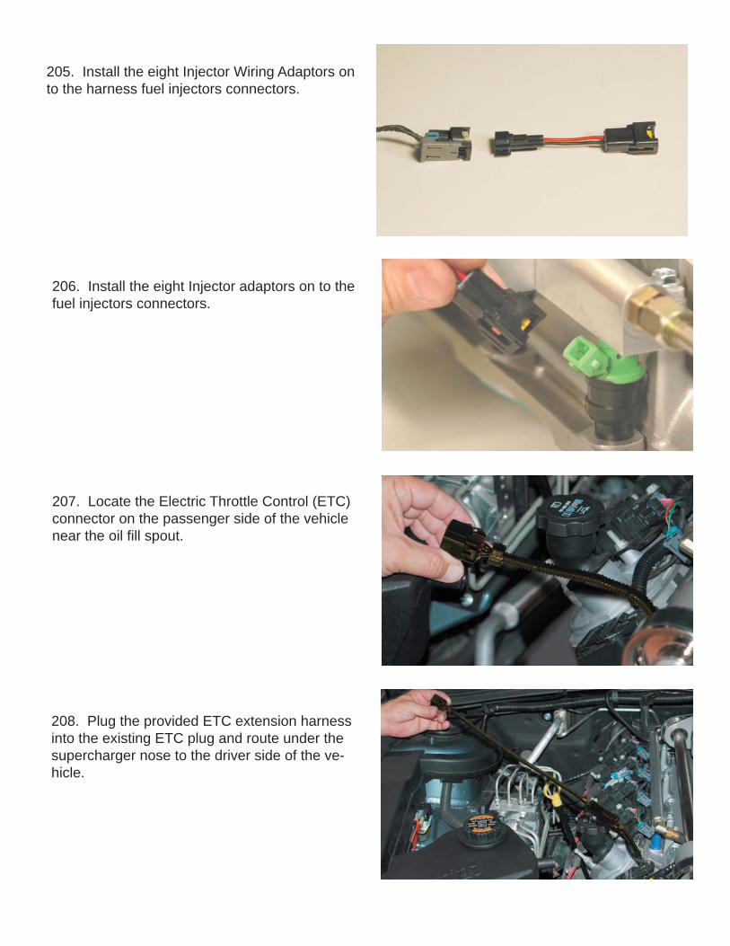
205. Install the eight Injector Wiring Adaptors on to the harness fuel injectors connectors.
206. Install the eight Injector adaptors on to the fuel injectors connectors.
207. Locate the Electric Throttle Control (ETC) connector on the passenger side of the vehicle near the oil fi ll spout.
208. Plug the provided ETC extension harness into the existing ETC plug and route under the supercharger nose to the driver side of the ve-hicle.

209. Install the ETC connector onto the throttle body.
210. Locate the Manifold (ETC) connector and peel back the tape and split-loom to expose the wires. Cut the wires approximately three inches from the connector.
211. Install the new MAP harness to the original wires using the crimp/shrink connectors supplied. The new harness wires are all white, so care must be take so the new white wires are in the same positions as the colored wires on the origi-nal connector. Strip about ¼” of insulation from the ends of all the wires. Crimp the connectors on and shrink the insulation so that it contracts around the wires completely.
212. Connect the extended MAP connect to the MAP sensor on the back of the supercharger manifold.

213. Locate the MAF sensor connector and peel back the tape and split loom to expose the wires. Approximately 3” from the connector cut all the wires.
MAF ConnectorMAF Connector
214. Pull the wires out of the tape from the wiring harness. Connect the Tan wires from the har-ness to the new supplied Intake Air Temperature (IAT) harness with the crimp/shrink connectors. Either TAN wire can be connected to either white wire of the IAT harness. Note: The two tan wires on the MAF connector will no longer be used.
215. Extend the remaining three wires of the MAF harness using the supplied color coded wire and crimp/shrink connectors to connect to the MAF connector. (Note that the two tan wires on the MAF connector will no longer be used.) Cover the extended harness and the new IAT branch with the split loom supplied.
IAT HarnessIAT Harness
Tan wiresTan wires
Extended MAF Extended MAF HarnessHarness
IAT ConnectorIAT Connector
216. Route the IAT harness under the fuel rail and plug the IAT connector into the IAT sensor.
IAT SensorIAT Sensor

218. Re-install the computer on the mounting bracket using the original fastener and a 10mm socket wrench. Note: If your vehicle has a auto-matic transmission, you will also need to re-install the transmission control computer located on the back side of the mounting bracket.
219. Replace the computer connectors in their original positions, making sure to lock them in place by pushing the grey levers towards the har-ness. Secure the connectors by inserting the red lock keys in position.
217. Route the extended MAF harness to the MAF and connect it.
220. Replace the brake duct, front and rear splash panels and spoiler in the passenger side wheel well. Re-install the road wheel and torque the lug nuts to 110 Ft-Lbs.

221. Fill the radiator reservoir with a 50:50 mix-ture of purifi ed water and GM approved engine coolant only. After the initial start up and the en-gine has come to operating temperature, recheck the fl uid level in the reservoir and all the hose connections.
222. Temporarily lift the intercooler reservoir out of the way to re-connect the battery ground terminal.
223. Fill the intercooler reservoir with a 50:50 mixture of purifi ed water and GM approved en-gine coolant only. The intercooler system will hold approximately 6 quarts of liquid. Fill the res-ervoir until the fl uid level comes to about one and a quarter inch from the top edge of the fi ller neck.
224. Using a straight blade screwdriver. Open the bleed valve to let any trapped air escape form the intercooler system. Some coolant will be lost when bleeding the system. Add coolant as nec-essary to the reservoir and continue to bleed the system until you can get a steady stream of cool-ant from the valve for over one minute. Check the intercooler reservoir level and re-open the bleed valve as needed.

After the initial test drive gradually work the vehicle to wide open throttle runs, listen for any engine detonation (pinging). If engine detona-tion is present let up on the throttle immediately. Most detonation is caused by octane gasoline still in the tank. Premium fuel must be used.
Please enjoy you “Magna Charged” performance responsibly.
225. Start the vehicle for 5 seconds and shut off, once again check for fuel leaks and supercharger belt alignment. Check radiator and intercooler reservoir levels. Test drive vehicle for the fi rst few miles under normal driving conditions, listen for any noises, vibrations, engine miss fi re or anything that does not seem normal. The super-charger does have a slight whining noise under boost conditions, which is normal. After the initial start up and the engine has come to operating temperature, recheck the coolant level in the intercooler reservoir and open the valve again to bleed any residual air trapped in the system. Check all the hose connections.
Use only premium fuel, 91 octane or better.Use only premium fuel, 91 octane or better.
MAGNACHARGER TURBOS SUPERCHARGERS KITS