
C2Sim: C2 and Simulation Systems that have been Implemented Educational Notes/STO-EN... · C2Sim:...
10
STO-EN-MSG-141 9 - 1 C2Sim: C2 and Simulation Systems that have been Implemented Mr. Adam Brook QinetiQ Cody Technology Park Ively Road, Farnborough Hampshire, GU14 0LX UNITED KINGDOM [email protected] ABSTRACT This paper is one of a coordinated set prepared for a NATO Modelling and Simulation Group Lecture Series in Command and Control – Simulation Interoperability (C2Sim). This paper provides examples of C2 and simulation systems that have been implemented using C2Sim standards (C-BML and MSDL) and discusses some of the technical approaches used to achieve interoperable systems. 1.0 INTRODUCTION This paper reprises examples of C2 and simulation systems that have been implemented using C2Sim standards (C-BML and MSDL). The work covered relates specifically to the UK systems discussed in other papers in this set of lectures but in many cases will apply equally well to other countries’ national systems. It also looks at some of the implementational aspects and gives a number of observations drawn from experiences of their use. 2.0 EXAMPLE FEDERATIONS The earlier papers in this series looked at specific national and coalition C2Sim developments, including 1 : • FRA-GBR: Support to Anglo-French Interoperability Readiness (SAFIR) • C2: SIR, SICF, BCIP 5.4 • M&S: APLET, SWORD, JSAF • FRA-DEU COMELEC Co-operation Programme • C2: SICF, FIS-H, C2LG-GUI • M&S: SWORD, KORA • MSG 085 and Earlier Experimentation • C2: SICF, ICC, 9LANDBMS, SITAWARE, ESRI COP Viewer, JADOCS, ISIS, CAPES, C2PC, JCHAT, TALOS, C2LG-GUI, BattleView • M&S: APLET, JSAF, OneSAF, TALOS-SIM, VBS2, VR-Forces This gives at least sixteen C2 systems and eight simulations. It is neither definitive nor exhaustive, not including the various robotic systems and experimental prototypes, but indicative of the range of systems used and investigated. Over time lessons identified and learned from these events have been used to enhance 1 Where known, acronyms are expanded at the end of this document.
Transcript of C2Sim: C2 and Simulation Systems that have been Implemented Educational Notes/STO-EN... · C2Sim:...

STO-EN-MSG-141 9 - 1
C2Sim: C2 and Simulation Systems that have been Implemented
Mr. Adam Brook QinetiQ
Cody Technology Park Ively Road, Farnborough Hampshire, GU14 0LX UNITED KINGDOM
ABSTRACT This paper is one of a coordinated set prepared for a NATO Modelling and Simulation Group Lecture Series in Command and Control – Simulation Interoperability (C2Sim). This paper provides examples of C2 and simulation systems that have been implemented using C2Sim standards (C-BML and MSDL) and discusses some of the technical approaches used to achieve interoperable systems.
1.0 INTRODUCTION
This paper reprises examples of C2 and simulation systems that have been implemented using C2Sim standards (C-BML and MSDL). The work covered relates specifically to the UK systems discussed in other papers in this set of lectures but in many cases will apply equally well to other countries’ national systems. It also looks at some of the implementational aspects and gives a number of observations drawn from experiences of their use.
2.0 EXAMPLE FEDERATIONS
The earlier papers in this series looked at specific national and coalition C2Sim developments, including1:
• FRA-GBR: Support to Anglo-French Interoperability Readiness (SAFIR)
• C2: SIR, SICF, BCIP 5.4
• M&S: APLET, SWORD, JSAF
• FRA-DEU COMELEC Co-operation Programme
• C2: SICF, FIS-H, C2LG-GUI
• M&S: SWORD, KORA
• MSG 085 and Earlier Experimentation
• C2: SICF, ICC, 9LANDBMS, SITAWARE, ESRI COP Viewer, JADOCS, ISIS, CAPES, C2PC, JCHAT, TALOS, C2LG-GUI, BattleView
• M&S: APLET, JSAF, OneSAF, TALOS-SIM, VBS2, VR-Forces
This gives at least sixteen C2 systems and eight simulations. It is neither definitive nor exhaustive, not including the various robotic systems and experimental prototypes, but indicative of the range of systems used and investigated. Over time lessons identified and learned from these events have been used to enhance
1 Where known, acronyms are expanded at the end of this document.

C2Sim: C2 and Simulation Systems that have been Implemented
9 - 2 STO-EN-MSG-141
the capabilities of the systems used, the supporting C2Sim standards, MSDL and C-BML and the necessary processes needed to create new configurations.
3.0 ACHIEVING C2SIM INTEROPERABILITY
This section describes some of the technical aspects which need to be considered to achieve interoperability in a C2Sim system with particular reference to the UK. The UK has taken a number of legacy systems to form interoperable systems, informing C2Sim research activities: looking at the utility of such systems; supporting the development of new approaches to training, mission rehearsal, doctrinal development; and so forth. This is all encapsulated in the concept of a C2Sim Test-bed. This test-bed provides an architecture capable of being adapted or extended for new use cases. Other nations have also developed national architectures and some of these have been referred to in other lectures in this series, e.g. the French Expertise et Logiciels pour les Liens d’Interopérabilité Permanents des Simulations et de leur Environnement (ELLIPSE) system [1]; the German-developed C2LG-GUI, web services and KORA simulation extensions and the work of the USA Simulation to Mission Command Interoperability (SIMCI) programme.
3.1 Architecture Models The UK C2Sim test-bed has been recorded in a [UK] Ministry of Defence Architectural Framework [2] (MODAF) model. Similar frameworks are available in the USA and NATO: DODAF and NAF. The UK MODAF model currently includes:
• Operational views (high and low-level operations, roles of participant players, initialisation and execution phases);
• System views (systems participating, linkages and main data flows); • Technical views (processes and standards referenced).
Figure 1 shows one of the MODAF System Views of the UK C2Sim test-bed architecture, in this case as configured for MSG-085 experimentation and connected to other NATO systems. The architectural framework provides a way of organising and linking use cases, requirements, ideas and concepts, information, processes, system and services specifications, etc. This approach can be particularly useful in a collaborative environment.
Figure 1: MODAF System View of UK C2Sim Test-bed.

C2Sim: C2 and Simulation Systems that have been Implemented
STO-EN-MSG-141 9 - 3
3.2 Systems Engineering The related but more detailed systems engineering aspects may be developed and recorded using the Unified Modelling Language (UML) [3]. The UML model allows the system components to be defined at the different levels of application and may also be used to link user and system requirements with their component and sub-component designs.
Figure 2 shows a UML diagram, in this case developed for Defence Research & Development Canada (DRDC), with system components for C-BML tasking and reporting through a common C-BML messaging web-service middleware (Scripted Battle Management Language (SBML) or Coalition Battle Management Services (CBMS)). This particular framework had its origin in the UK as an experimental prototype, was refined in Canada and has been extended again in the UK to bring in more C2 and simulation systems.
JSAF BML INTERFACE 2.0 ARCHITECTURE
SYSTEM TO BML TASKING
BML TO SYSTEM REPORTING SYSTEM TO BML REPORTING
BML TO SYSTEM TASKING
BML Server
BmlServ erIF
«interface»IBmlServ erWrapper
Bml2SysTaskTranslator
SysTasker
SysReportReceiv er
SysReport2BmlTranslator
:BmlParser
:BmlMsgSender
:BmlMsgReceiv er
:BmlMsgReceiv er
:BmlParser
SysTaskReceiv er
SysTask2BmlTranslator:BmlMsgSender
Bml2SysReportTranslator
SysReportDispatcher
:External Component
:External Component
:External Component
:External Component
«flow»
«flow»
«flow»
«flow»
«flow»
«flow»
«flow»
«flow»«flow»
«flow»
«flow»
«flow»
«flow»
«flow»
«flow»
«flow»
«flow»
«flow»
Can connect to SBML or CBMS Server
Red components are system specific
TASKING
REPORTING
Yellow components are templates for message
translators and wrappers
Green components are common to all C-BML
servers
Figure 2: System View of C2Sim Test-bed.
At this point some of the specific systems used in the UK C2Sim test-bed will be discussed further.
3.3 Specific Systems
3.3.1 ICC
The NATO Integrated Command and Control system (ICC) is one of a number of Functional Area C2 tools used in NATO (see [4] for full list). ICC supports air C2 planning and operations at Joint Force Command (JFC), Air Component Command (ACC) and Combined Air Operations Centre (CAOC) levels. It may also be integrated with a number of other NATO C2 tools. The software is client/server system supported by an underlying Oracle relational database. The application consists of a number of components of which the principal ones are: for preparing Airspace Control Means (ACMs), Airspace Coordination Orders (ACOs) and Air Tasking Orders (ATOs); and displaying a Common Operational Picture (COP) or Recognised Air/Surface Picture (RAP/RSP).
ICC may be used in conjunction with pre-planned and time-sensitive targeting tools, Joint Targeting System (JTS) and Flexible Advanced C2 Services for Time-Sensitive Targeting (FAST). It may also be used with Intelligence, Surveillance, Target Acquisition, and Reconnaissance (ISTAR) systems including the NATO Coalition Shared Database (CSD).
Figure 3 shows the ICC mission planning interface used to prepare ATOs.

C2Sim: C2 and Simulation Systems that have been Implemented
9 - 4 STO-EN-MSG-141
TaskOrg2D Map
MissionEditor
MissionTote & ATO
Resources
ACMs
Figure 3: ICC Mission Planning Interface.
3.3.2 NIRIS
The Networked Interoperable Real-time Information Services (NIRIS) provide a number of capabilities designed for use with operational information systems but equally of use in the C2Sim domain. Of these the Network Port Manager (NPM) and Trackstore Synchronisation Server (TSS) are used in the test-bed. The NPM provides basic network connectivity and the TSS creates tracks from operational messages in a number of standard formats, LINK-11, LINK-16, Over The Horizon-Gold (OTH-G), NATO Friendly Force Identification (NFFI), etc, received using the NPM services. The track store may be realised by ICC as a COP, RAP or RSP with real-time tracks shown on an ICC map using APP6-A symbology.
3.3.3 JSAF
JSAF is the Joint Semi-Automated Force simulation. It is a Computer Generated Force (CGF) model which operates at the entity and unit level. The JSAF architecture provides:
• Physics-based models for platforms: aircraft, ships, vehicles, etc;
• Components: mobility, sensor, weapon, communication, etc;
• Natural environment: topography and feature, atmospheric and ocean, illumination;
• Organisational representations: unit and equipment hierarchies, allegiance;
• Behavioural models for explicit, implicit and reactive behaviours;
• Overlays and graphics;
• Graphical User Interface (GUI) components; and
• Run-time services: DIS/HLA simulation interfaces, schedulers, event handlers, status look-up, etc.
JSAF is usually run as a networked, distributed real-time simulation. JSAF can be modified for C2-Sim because it can be initialised with structured data and has accessible, non-scripted behavioural models. Its Federation Object Model (FOM) supports: tasking interactions, tasking state, tasking and background parameters and behaviour status.
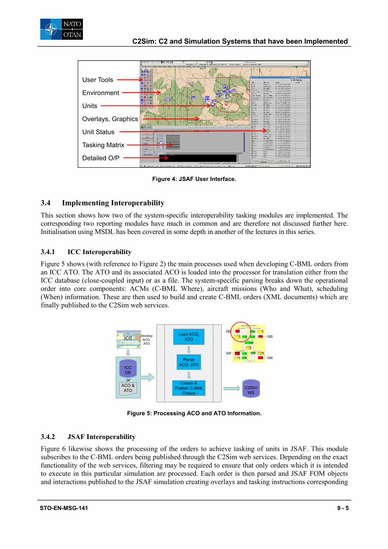
Figure 4 shows the JSAF simulation interface with some of the salient details highlighted.
C2Sim: C2 and Simulation Systems that have been Implemented
STO-EN-MSG-141 9 - 5
User Tools
Units
Unit Status
Tasking Matrix
Environment
Overlays, Graphics
Detailed O/P
Figure 4: JSAF User Interface.
3.4 Implementing Interoperability This section shows how two of the system-specific interoperability tasking modules are implemented. The corresponding two reporting modules have much in common and are therefore not discussed further here. Initialisation using MSDL has been covered in some depth in another of the lectures in this series.
3.4.1 ICC Interoperability
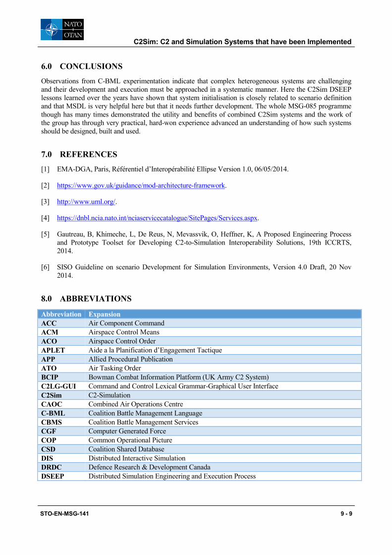
Figure 5 shows (with reference to Figure 2) the main processes used when developing C-BML orders from an ICC ATO. The ATO and its associated ACO is loaded into the processor for translation either from the ICC database (close-coupled input) or as a file. The system-specific parsing breaks down the operational order into core components: ACMs (C-BML Where), aircraft missions (Who and What), scheduling (When) information. These are then used to build and create C-BML orders (XML documents) which are finally published to the C2Sim web services.
C2Sim WS
ICC
ICC DB
ACO & ATO
Parse ACO, ATO
Create & Publish C-BML
Orders
Load ACO, ATO
or
Develop ACO, ATO
Figure 5: Processing ACO and ATO Information.
3.4.2 JSAF Interoperability
Figure 6 likewise shows the processing of the orders to achieve tasking of units in JSAF. This module subscribes to the C-BML orders being published through the C2Sim web services. Depending on the exact functionality of the web services, filtering may be required to ensure that only orders which it is intended to execute in this particular simulation are processed. Each order is then parsed and JSAF FOM objects and interactions published to the JSAF simulation creating overlays and tasking instructions corresponding

C2Sim: C2 and Simulation Systems that have been Implemented
9 - 6 STO-EN-MSG-141
to the ACMs referred to in the ATO’s associated ACO and the missions in the ATO. At this point the simulation is ready to execute the order.
Internal format with permanent
or transient storage
C2Sim WS
Parse C-BMLCreate & Publish
Overlays and Tactical Graphics
Populate, Schedule and Publish Tasking
Interaction
Subscribe(Filter if
necessary)
JSAF
Figure 6: JSAF Processing C-BML for JSAF Tasking.
3.4.3 Some C-BML Challenges
This system connects a C2 application, ICC, with a simulation, JSAF, using C-BML as an intermediate enabler. This is basically a three stage process: create order in ICC, process intermediate C-BML and execute in simulation. At each stage there is a change between the representation of what is fundamentally the same information and thus a potential for ambiguity and information mismatch. To minimise any adverse effects at these translation points it is important that the C-BML is adequately and unambiguously defined. This definition process is currently the focus of one of the main efforts of the SISO C2Sim Product Development Group.
4.0 REPORTING
4.1 Some Observations on Reports in C2Sim Systems C2Sim systems use the simulations to create various types of report which are sent to the C2 domain. Here they may be further processed (for example, aggregated), forwarded (doubtless adding extra delay) or displayed to the user as appropriate. It must be remembered that simulation provides Ground Truth and that anything else, however accurate is Perceived Truth. This is due to a number of factors such as: latency, sampling frequency, sensor errors, identification errors, etc, all of which increase inaccuracy.
4.2 Displaying Reports C-BML reports may be categorised in two sets:
• Positions, Tracks, Event locations – These should all be displayed graphically on a map display; and
• Other status, e.g. Logistics, Mission reports, Acknowledgements – These are all better displayed in a written list.
A C2 display, say of a COP, is merely an extension of the operator’s memory, albeit a very useful one.
Experience shows the need to get display symbology correct. Military users expect to see consistent symbology across different systems, particularly coalition systems which may use different operational message sets. MSDL is very helpful here as it can include APP-6 symbol codes for units/equipment. Mapping to operational message sets is important, not all use APP-6 codes, e.g. OTH-Gold.

C2Sim: C2 and Simulation Systems that have been Implemented
STO-EN-MSG-141 9 - 7
4.3 Overloading C2 Systems with Reports Overloading C2 systems and middleware with reports is a potential difficulty. If this is the case then it may be necessary to throttle, filter or sieve reports, possibly on both or either side of server.
4.4 Time-Stamping Reports Time-stamping of reports is also a challenge and needs to be addressed in the federation agreements. For example, an operational scenario may be set to occur on a particular date and the message time stamps should correspond. Another case to consider is when a simulation is running in faster-than-real-time mode and generating reports. This will create time stamps dated in advance of the C2 system; some legacy C2 systems will reject messages with out-of-bounds time stamps. Re-running logged C-BML reports may also be difficult with some C2 systems.
5.0 SUPPORTING APPROACHES
A number of supporting activities should be considered when creating a C2Sim system. The development of recognised processes adapted to the needs of developing C2Sim systems is borne of the practical experience of groups such as MSG-085 and the various national and coalition activities.
5.1 DSEEP Overlay for C2Sim The C2Sim Distributed Simulation Engineering and Execution Process (DSEEP), Figure 7, was developed by MSG-085 [5] to help capture the systems engineering processes required to support a C2Sim federation, particularly the System Design Agreements. Originally DSEEP, an enhancement of the SISO Federation Development and Execution Process (FEDEP), was applied only to the design and development of High Level Architecture (HLA) federations but soon was being used in a number of other similar, but non-HLA areas. The recommendation of MSG-085 is to use a C2Sim DSEEP Overlay when developing complex C2Sim federations.
C2SIMXML
Schema
ScenarioDocumentation
C2SIM Federation
RequirementsXML Schema Extensions ?
Extensions required
Figure 7: DSEEP Overlay for C2Sim.

C2Sim: C2 and Simulation Systems that have been Implemented
9 - 8 STO-EN-MSG-141
5.2 SISO Guideline on Scenario Development
Operational Scenario
Conceptual Scenario
Executable Scenario
User M&S Experts Operator
RefineRefine
Figure 8: GSD Relationship Between Operational and Executable Scenarios.
The SISO Guideline on Scenario Development (GSD) [6] breaks down the development of an a scenario into three separate phases, the operational, conceptual and executable. Within each of these phases consideration needs to be given to defining the initial state, the course of events and the termination conditions.
The GSD formalises four maturity levels for the specifications each of the different development phases and indicates appropriate standards and tools which are appropriate to use at each level and phase. C2Sim standards, C-BML and MSDL are considered very appropriate for the highest formal scenario maturity level specification, especially for the operational and executable scenarios.
5.3 M&S and C2Sim as Services NATO MSG-136 research programme is investigating the use of cloud-based computing systems to support Modelling and Simulation as a Service (MSaaS). In such systems clients access Services, Platforms and Infrastructure ‘in a cloud environment’. A question which needs to be asked is: “ What is require to extend this to include C2Sim as a Service?” The C2Sim community has built up considerable experience using software services to support its aims and these are discussed in greater detail in other lectures in this series. However, it is worth functionality considering just what would be required to provide C2Sim services in such an environment. The following list is indicative of the services which should be supported:
• Initialisation, development, validation, storing, merging and distribution
• Exchange of C2Sim messages – push/pull, pub/sub, unicast, multicast, broadcast,
• Addressing, Routing, Acknowledgement, Error-handling
• Logging, replay and analysis of C2Sim messages
• Augmentation of C2Sim messages
• Translation of C2Sim messages
• Exercise Management:
• Coordination/monitoring of participants – which sites/players are joined, their capabilities, status, etc.
• Coordination/monitoring of applications – which applications are joined, etc.
• Security – which data is it possible to exchange and with whom?
• Time management
• Federation agreements
C2Sim: C2 and Simulation Systems that have been Implemented
STO-EN-MSG-141 9 - 9
6.0 CONCLUSIONS
Observations from C-BML experimentation indicate that complex heterogeneous systems are challenging and their development and execution must be approached in a systematic manner. Here the C2Sim DSEEP lessons learned over the years have shown that system initialisation is closely related to scenario definition and that MSDL is very helpful here but that it needs further development. The whole MSG-085 programme though has many times demonstrated the utility and benefits of combined C2Sim systems and the work of the group has through very practical, hard-won experience advanced an understanding of how such systems should be designed, built and used.
7.0 REFERENCES
[1] EMA-DGA, Paris, Référentiel d’Interopérabilité Ellipse Version 1.0, 06/05/2014.
[2] https://www.gov.uk/guidance/mod-architecture-framework.
[3] http://www.uml.org/.
[4] https://dnbl.ncia.nato.int/nciaservicecatalogue/SitePages/Services.aspx.
[5] Gautreau, B, Khimeche, L, De Reus, N, Mevassvik, O, Heffner, K, A Proposed Engineering Process and Prototype Toolset for Developing C2-to-Simulation Interoperability Solutions, 19th ICCRTS, 2014.
[6] SISO Guideline on scenario Development for Simulation Environments, Version 4.0 Draft, 20 Nov 2014.
8.0 ABBREVIATIONS
Abbreviation Expansion ACC Air Component Command ACM Airspace Control Means ACO Airspace Control Order APLET Aide a la Planification d’Engagement Tactique APP Allied Procedural Publication ATO Air Tasking Order BCIP Bowman Combat Information Platform (UK Army C2 System) C2LG-GUI Command and Control Lexical Grammar-Graphical User Interface C2Sim C2-Simulation CAOC Combined Air Operations Centre C-BML Coalition Battle Management Language CBMS Coalition Battle Management Services CGF Computer Generated Force COP Common Operational Picture CSD Coalition Shared Database DIS Distributed Interactive Simulation DRDC Defence Research & Development Canada DSEEP Distributed Simulation Engineering and Execution Process

C2Sim: C2 and Simulation Systems that have been Implemented
9 - 10 STO-EN-MSG-141
Abbreviation Expansion ELLIPSE Expertise et Logiciels pour les Liens d’Interopérabilité Permanents des Simulations et de leur
Environnement FAST [NATO] Flexible Advanced C2 Services for Time-Sensitive Targeting FEDEP Federation Development and Execution Process FIS-H FüInfoSysH (German Army C2 System) FOM Federation Object Model GSD [SISO] Guideline on Scenario Development GUI Graphical User Interface HLA High Level Language ICC [NATO] Integrated Command and Control ISTAR Intelligence, Surveillance, Target Acquisition, and Reconnaissance JFC Joint Force Command JSAF Joint Semi-Automated Force JTS [NATO] Joint Targeting System
FAST – Flexible Advanced C2 Services for Time-Sensitive Targeting KORA Korpsrahmen Simulationsmodell zur Offizierausbildung MODAF [UK] Ministry of Defence Architectural Framework MSaaS Modelling and Simulation as a Service MSDL Military Scenario Definition Language NFFI NATO Friendly Force Identification NIRIS Networked Interoperable Real-time Information Services NPM Network Port Manager (NIRIS) OTH-G Over The Horizon-Gold RAP Recognised Air Picture RSP Recognised Surface Picture SBML Scripted Battle Management Language SICF Système d’Information pour le Commandement des Forces SIMCI Simulation to Mission Command Interoperability SIR Système d’Information Régimentaire SISO Simulation Interoperability Standards Organisation TSS Trackstore Synchronisation Server (NIRIS) UML Unified Modelling Language VBS2 Virtual Battle Space 2


