by Dean Williams - VINH QUANG RC MODELSIn this case, my usual preference for a styrofoam vegie box...
9
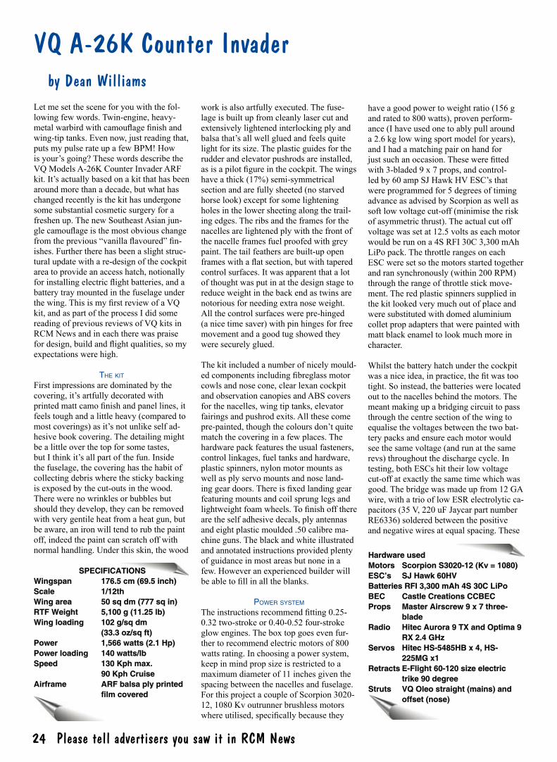
24 Radio Control Model News Issue 100 February 2010 Please tell advertisers you saw it in RCM News 24 SPECIFICATIONS Wingspan 176.5 cm (69.5 inch) Scale 1/12th Wing area 50 sq dm (777 sq in) RTF Weight 5,100 g (11.25 lb) Wing loading 102 g/sq dm (33.3 oz/sq ft) Power 1,566 watts (2.1 Hp) Power loading 140 watts/lb Speed 130 Kph max. 90 Kph Cruise Airframe ARF balsa ply printed film covered VQ A-26K Counter Invader by Dean Williams Let me set the scene for you with the fol- lowing few words. Twin-engine, heavy- metal warbird with camouflage finish and wing-tip tanks. Even now, just reading that, puts my pulse rate up a few BPM! How is your’s going? These words describe the VQ Models A-26K Counter Invader ARF kit. It’s actually based on a kit that has been around more than a decade, but what has changed recently is the kit has undergone some substantial cosmetic surgery for a freshen up. The new Southeast Asian jun- gle camouflage is the most obvious change from the previous “vanilla flavoured” fin- ishes. Further there has been a slight struc- tural update with a re-design of the cockpit area to provide an access hatch, notionally for installing electric flight batteries, and a battery tray mounted in the fuselage under the wing. This is my first review of a VQ kit, and as part of the process I did some reading of previous reviews of VQ kits in RCM News and in each there was praise for design, build and flight qualities, so my expectations were high. THE KIT First impressions are dominated by the covering, it’s artfully decorated with printed matt camo finish and panel lines, it feels tough and a little heavy (compared to most coverings) as it’s not unlike self ad- hesive book covering. The detailing might be a little over the top for some tastes, but I think it’s all part of the fun. Inside the fuselage, the covering has the habit of collecting debris where the sticky backing is exposed by the cut-outs in the wood. There were no wrinkles or bubbles but should they develop, they can be removed with very gentile heat from a heat gun, but be aware, an iron will tend to rub the paint off, indeed the paint can scratch off with normal handling. Under this skin, the wood work is also artfully executed. The fuse- lage is built up from cleanly laser cut and extensively lightened interlocking ply and balsa that’s all well glued and feels quite light for its size. The plastic guides for the rudder and elevator pushrods are installed, as is a pilot figure in the cockpit. The wings have a thick (17%) semi-symmetrical section and are fully sheeted (no starved horse look) except for some lightening holes in the lower sheeting along the trail- ing edges. The ribs and the frames for the nacelles are lightened ply with the front of the nacelle frames fuel proofed with grey paint. The tail feathers are built-up open frames with a flat section, but with tapered control surfaces. It was apparent that a lot of thought was put in at the design stage to reduce weight in the back end as twins are notorious for needing extra nose weight. All the control surfaces were pre-hinged (a nice time saver) with pin hinges for free movement and a good tug showed they were securely glued. The kit included a number of nicely mould- ed components including fibreglass motor cowls and nose cone, clear lexan cockpit and observation canopies and ABS covers for the nacelles, wing tip tanks, elevator fairings and pushrod exits. All these come pre-painted, though the colours don’t quite match the covering in a few places. The hardware pack features the usual fasteners, control linkages, fuel tanks and hardware, plastic spinners, nylon motor mounts as well as ply servo mounts and nose land- ing gear doors. There is fixed landing gear featuring mounts and coil sprung legs and lightweight foam wheels. To finish off there are the self adhesive decals, ply antennas and eight plastic moulded .50 calibre ma- chine guns. The black and white illustrated and annotated instructions provided plenty of guidance in most areas but none in a few. However an experienced builder will be able to fill in all the blanks. POWER SYSTEM The instructions recommend fitting 0.25- 0.32 two-stroke or 0.40-0.52 four-stroke glow engines. The box top goes even fur- ther to recommend electric motors of 800 watts rating. In choosing a power system, keep in mind prop size is restricted to a maximum diameter of 11 inches given the spacing between the nacelles and fuselage. For this project a couple of Scorpion 3020- 12, 1080 Kv outrunner brushless motors where utilised, specifically because they have a good power to weight ratio (156 g and rated to 800 watts), proven perform- ance (I have used one to ably pull around a 2.6 kg low wing sport model for years), and I had a matching pair on hand for just such an occasion. These were fitted with 3-bladed 9 x 7 props, and control- led by 60 amp SJ Hawk HV ESC’s that were programmed for 5 degrees of timing advance as advised by Scorpion as well as soft low voltage cut-off (minimise the risk of asymmetric thrust). The actual cut off voltage was set at 12.5 volts as each motor would be run on a 4S RFI 30C 3,300 mAh LiPo pack. The throttle ranges on each ESC were set so the motors started together and ran synchronously (within 200 RPM) through the range of throttle stick move- ment. The red plastic spinners supplied in the kit looked very much out of place and were substituted with domed aluminium collet prop adapters that were painted with matt black enamel to look much more in character. Whilst the battery hatch under the cockpit was a nice idea, in practice, the fit was too tight. So instead, the batteries were located out to the nacelles behind the motors. The meant making up a bridging circuit to pass through the centre section of the wing to equalise the voltages between the two bat- tery packs and ensure each motor would see the same voltage (and run at the same revs) throughout the discharge cycle. In testing, both ESCs hit their low voltage cut-off at exactly the same time which was good. The bridge was made up from 12 GA wire, with a trio of low ESR electrolytic ca- pacitors (35 V, 220 uF Jaycar part number RE6336) soldered between the positive and negative wires at equal spacing. These Hardware used Motors Scorpion S3020-12 (Kv = 1080) ESC’s SJ Hawk 60HV Batteries RFI 3,300 mAh 4S 30C LiPo BEC Castle Creations CCBEC Props Master Airscrew 9 x 7 three- blade Radio Hitec Aurora 9 TX and Optima 9 RX 2.4 GHz Servos Hitec HS-5485HB x 4, HS- 225MG x1 Retracts E-Flight 60-120 size electric trike 90 degree Struts VQ Oleo straight (mains) and offset (nose)
Transcript of by Dean Williams - VINH QUANG RC MODELSIn this case, my usual preference for a styrofoam vegie box...
24 RadioControlModelNewsIssue100February2010Please tell advertisers you saw it in RCM News 24
SPECIFICATIONSWingspan 176.5cm(69.5inch)Scale 1/12thWingarea 50sqdm(777sqin)RTFWeight 5,100g(11.25lb)Wingloading 102g/sqdm (33.3oz/sqft)Power 1,566watts(2.1Hp)Powerloading 140watts/lbSpeed 130Kphmax. 90KphCruiseAirframe ARFbalsaplyprinted filmcovered
VQ A-26K Counter Invader by Dean Williams Letmesetthesceneforyouwiththefol-lowingfewwords.Twin-engine,heavy-metal warbird with camouflage finish and wing-tiptanks.Evennow,justreadingthat,putsmypulserateupafewBPM!Howisyour’sgoing?ThesewordsdescribetheVQModelsA-26KCounterInvaderARFkit.It’sactuallybasedonakitthathasbeenaroundmorethanadecade,butwhathaschangedrecentlyisthekithasundergonesomesubstantialcosmeticsurgeryforafreshenup.ThenewSoutheastAsianjun-gle camouflage is the most obvious change from the previous “vanilla flavoured” fin-ishes.Furthertherehasbeenaslightstruc-turalupdatewithare-designofthecockpitareatoprovideanaccesshatch,notionallyfor installing electric flight batteries, and a batterytraymountedinthefuselageunderthe wing. This is my first review of a VQ kit,andaspartoftheprocessIdidsomereadingofpreviousreviewsofVQkitsinRCMNewsandineachtherewaspraisefor design, build and flight qualities, so my expectationswerehigh.
The kiT Firstimpressionsaredominatedbythecovering,it’sartfullydecoratedwithprinted matt camo finish and panel lines, it feelstoughandalittleheavy(comparedtomostcoverings)asit’snotunlikeselfad-hesivebookcovering.Thedetailingmightbealittleoverthetopforsometastes,butIthinkit’sallpartofthefun.Insidethefuselage,thecoveringhasthehabitofcollectingdebriswherethestickybackingisexposedbythecut-outsinthewood.Therewerenowrinklesorbubblesbutshouldtheydevelop,theycanberemovedwithverygentileheatfromaheatgun,butbeaware,anironwilltendtorubthepaintoff,indeedthepaintcanscratchoffwithnormalhandling.Underthisskin,thewood
workisalsoartfullyexecuted.Thefuse-lageisbuiltupfromcleanlylasercutandextensivelylightenedinterlockingplyandbalsa that’s all well glued and feels quite lightforitssize.Theplasticguidesfortherudderandelevatorpushrodsareinstalled,as is a pilot figure in the cockpit. The wings haveathick(17%)semi-symmetricalsectionandarefullysheeted(nostarvedhorselook)exceptforsomelighteningholesinthelowersheetingalongthetrail-ingedges.Theribsandtheframesforthenacellesarelightenedplywiththefrontofthenacelleframesfuelproofedwithgreypaint.Thetailfeathersarebuilt-upopenframes with a flat section, but with tapered controlsurfaces.Itwasapparentthatalotofthoughtwasputinatthedesignstagetoreduceweightinthebackendastwinsarenotoriousforneedingextranoseweight.Allthecontrolsurfaceswerepre-hinged(anicetimesaver)withpinhingesforfreemovementandagoodtugshowedtheyweresecurelyglued.
Thekitincludedanumberofnicelymould-ed components including fibreglass motor cowlsandnosecone,clearlexancockpitandobservationcanopiesandABScoversforthenacelles,wingtiptanks,elevatorfairingsandpushrodexits.Allthesecomepre-painted, though the colours don’t quite matchthecoveringinafewplaces.Thehardwarepackfeaturestheusualfasteners,controllinkages,fueltanksandhardware,plasticspinners,nylonmotormountsaswellasplyservomountsandnoseland-ing gear doors. There is fixed landing gear featuringmountsandcoilsprunglegsandlightweight foam wheels. To finish off there aretheselfadhesivedecals,plyantennasandeightplasticmoulded.50calibrema-chineguns.Theblackandwhiteillustratedandannotatedinstructionsprovidedplentyofguidanceinmostareasbutnoneinafew.Howeveranexperiencedbuilderwillbe able to fill in all the blanks.
Power sysTem
The instructions recommend fitting 0.25-0.32two-strokeor0.40-0.52four-strokeglowengines.Theboxtopgoesevenfur-thertorecommendelectricmotorsof800wattsrating.Inchoosingapowersystem,keepinmindpropsizeisrestrictedtoamaximumdiameterof11inchesgiventhespacingbetweenthenacellesandfuselage.ForthisprojectacoupleofScorpion3020-12,1080Kvoutrunnerbrushlessmotorswhere utilised, specifically because they
haveagoodpowertoweightratio(156gandratedto800watts),provenperform-ance(Ihaveusedonetoablypullarounda2.6kglowwingsportmodelforyears),andIhadamatchingpaironhandforjust such an occasion. These were fitted with3-bladed9x7props,andcontrol-ledby60ampSJHawkHVESC’sthatwereprogrammedfor5degreesoftimingadvanceasadvisedbyScorpionaswellassoftlowvoltagecut-off(minimisetheriskofasymmetricthrust).Theactualcutoffvoltagewassetat12.5voltsaseachmotorwouldberunona4SRFI30C3,300mAhLiPopack.ThethrottlerangesoneachESCweresetsothemotorsstartedtogetherandransynchronously(within200RPM)throughtherangeofthrottlestickmove-ment.Theredplasticspinnerssuppliedinthekitlookedverymuchoutofplaceandweresubstitutedwithdomedaluminiumcolletpropadaptersthatwerepaintedwithmattblackenameltolookmuchmoreincharacter.
Whilstthebatteryhatchunderthecockpitwas a nice idea, in practice, the fit was too tight.Soinstead,thebatterieswerelocatedouttothenacellesbehindthemotors.Themeantmakingupabridgingcircuittopassthroughthecentresectionofthewingtoequalise the voltages between the two bat-terypacksandensureeachmotorwouldseethesamevoltage(andrunatthesamerevs)throughoutthedischargecycle.Intesting,bothESCshittheirlowvoltagecut-offatexactlythesametimewhichwasgood.Thebridgewasmadeupfrom12GAwire,withatriooflowESRelectrolyticca-pacitors(35V,220uFJaycarpartnumberRE6336)solderedbetweenthepositiveand negative wires at equal spacing. These
HardwareusedMotors ScorpionS3020-12(Kv=1080)ESC’s SJHawk60HVBatteriesRFI3,300mAh4S30CLiPoBEC CastleCreationsCCBECProps MasterAirscrew9x7three- blade Radio HitecAurora9TXandOptima9 RX2.4GHzServos HitecHS-5485HBx4,HS- 225MGx1RetractsE-Flight60-120sizeelectric trike90degreeStruts VQOleostraight(mains)and offset(nose)

Australia’slargestcirculatingR/CModelMagazine 25Australia’s widest read R/C flying magazine, RCM News Issue 119 May - June 2013 25
suppressvoltagespikesinducedalongthisextra45cmofwiring.Suchspikeshavethepotentialtooverloadanddestroythespeedcontrollers.Notgood.
Thiswiringwasalsousedtoprovideameans of getting power from the flight batteriestoaCastleCreationsCC-BECmountedinthefuselagetothensupplypowertotheradiogear.AnEC3plugsetwaswiredclosetooneendofthebridgesoeachdrivecanbeisolateduntiltheyareconnectedto(anddisconnectedfrom)theirrespectivebatteries.Thisistostoponeoftheexposed(male)Deansplugsgoingliveintheprocess.Onthebench,30secondsintoafullthrottlerunfromafullcharge,themotorswouldspinthe3-bladedpropsat12,800RPMon14.6voltsandeachpull54ampsfor788Wattsperside.Agoodoutcomethatwasprettydarnclosetothequoted performance requirement.
oTher biTs required
Additional items required include a 4-chan-nelradiosystemasabareminimumbutmorechannelswilldoabetterjobofit.Standard servos fit all around, the number willdependonpowersystem(6forfuelor4forelectric)andanadditionalmini-servocanbeemployedforindependentnosewheelsteering(metalgearrecommended).Afewextensionleadswillalsobeneeded.Retractsareoptional(butstronglyencour-aged),eitherairorelectrictosuita5Kgmodel.
Given the size and configuration of the model,acradletorestitinwhilstworkingonit(particularlyinthelatterstagesofcon-struction) and assembly at the field is good idea.Inthiscase,myusualpreferenceforastyrofoamvegieboxwasn’tgoingtocutitsoatimber(pine)cradlewasknockedup.
ItwasdesignedtoholdtheInvaderonitsbellyformountingthewingsandcheckingretractfunctionsandonitsbackforbatteryswaps.ItcanbepeggeddownsoitwillalsorestraintheInvaderatfullthrottle.
The build
To start, the first step of the building phase wasdeferred,thiswasthejoiningofthewings. Keeping them separate makes fit-tingallthehardwaremucheasier,startingwiththeaileronservos.Thesewereeasilymountedontherailsattachedtotheirre-spectivehatchcovers.Theserailswereonlybuttgluedtothecoversatthefactorywith
noadditionalbracing,soforextrahold,therailsweresecuredwithsmallscrews.Eachservoneededa30cmextensionleadandtheleadsweredrawnthroughthewingwith the handy factory fitted draw strings. Fittingthecontrolhornsandlinkagesfol-lowedstandardprocedure,exceptZbendswereemployedinsteadoftheadjustablekeepersontheservoarms,providingareli-ableandlowmaintenancesubstitute.
Whenmountingthemotors,theinstruc-tionsrecommendadistanceof104mmbetween the firewall and the front face of thepropadaptertoclearthecowls,thoughIfound100mmtobeplenty.Thismeantusingstandoffs(notsupplied)tomountthemotors.TheradialmountsoftheScor-pionmotorsaren’tverymeatysowerenotsuitabletobedirectlymountedtothestand-offs.Instead,supplementarymountsweresimplycutfrom6mmplyusinga
Powerful but light Scorpion motors
and SJ Hawk ESC’s provided
plenty of urge on 4S LiPo’s. Two
systems bridged at the battery
leads ensure the battery voltages
are balanced throughout
the flight. The bridge featured
electrolytic capacitors and , wiring to tap power off the
system for the radio via a Deans
micro connector
The Scorpions were screwed to 6
mm ply mounts, which were in turn bolted to
the firewalls on standoffs. A hole
was cut in the firewall to let
cooling air into the battery bay

26 RadioControlModelNewsIssue100February2010Please tell advertisers you saw it in RCM News 26
holesaw.Themotorswereattachedtothese,andtheseinturnwereboltedtothefirewalls using 3/16 mushroom head bolts, nylocnuts,aluminiumstandoffsandplentyofwasherstopreventcrushingtheply.Therewasnorightordownthrustbuiltintothe firewalls, and whilst a little bit of me wantedtoputatleastadashofdownthrustin,Ididresisttheurge.
SomecreativethinkingwasneededonhowtomountandaccesstheESCandLiPo behind the firewall. The former was easy,bothcouldbeheldtothesidesofthe
tankbaywithVelcro,withanadditionalVelcrostraptoholdtheLiPo.Gettingeasyaccessforbatterychangesmeantcuttingandformingahatchfromthelowernacellecovering.Themouldingsweretoughenoughtoholdtheirshapewhenthe14x7cmhatcheswerecutfreewithcarefulstrokesofasharpscalpel.Theopeningswerelineddowneachlongsidewiththinplyforthehatchestoseat,whilstshortlengthsofbambooskewerwereepoxiedtothefrontofthehatchtoholditdown.Com-merciallyavailablespringloadedlatcheswereusedtoholdtherearofthecovers
withtheaidofaplyplategluedtotherearoftheopeninganddrilledtoarrestthelatchpin.
Sothetwopowersystemscouldbecon-nectedbythebridgingcircuit,holesweredrilledthroughtheinnersidesofthetankbaysothewiringcouldpassthroughtheribopeningsinfrontofthemainspar.AholewascutinthelowerwingsheetingsothewiretoconnecttheBECcouldpassthroughintothefuselage.Alargeholewasalso cut in each firewall to let cooling air intothebatterybay,thewarmairwouldescapeoutthelandinggearopenings.
E-flight 60-120 sized 90 degree electric tri-cycleretractswerechosentoliftanddropthewheels,andprovidedformuchsim-plerinstallationandmaintenancethanairretracts.TheseweredressedupwithaVQModelsoffsetsprungoleostrutonthenosegearandVQModelsstraightoleostrutson
With plenty of room available, the standard sized radio gear was easily installed in the fuselage under the wing. The Castle BEC
sits on the redundant flight battery tray
Fuel tank bay directly behind the firewall provided plenty of room to house the LiPo battery and ESC
Above right; mounting rails were spaced for
standard size aileron servos and small screws were
used to provide extra grip as the
rails were only butt glued to the covers
Spaghetti anyone? The extension leads exited the centre of the lower wing
skin through neat grommets. Each was labelled and later colour coded with tape
to avoid mixing them up when connecting them to the receiver. Power was fed to an
external BEC from the wiring running through the wing centre section that
linked the two flight batteries
VQ A-26 Counter Invader

Australia’slargestcirculatingR/CModelMagazine 27Australia’s widest read R/C flying magazine, RCM News Issue 119 May - June 2013 27
themains.Fittingthestrutswasveryeasy,onlythemainsneededtobedrilledouttoacceptthe5mmmountingpinswhichwerecutfromthewirestrutssuppliedwiththeretracts.Thehubsofthekitwheelsalsoneededdrillingouttoaccepttheaxles,andspacerswereneededontheaxlestokeepthewheelsfromrubbingonthestruts.Flatspotsweregroundonthemountingpinsandaxleswheretheywereheldwithgrubscrews,andthegrubscrewswereheldwiththreadlocker.Themainsneededtobeorientedwiththescissorarmsforwardofthestruts(notscale)sothestrutretainingscrewwouldnotjamontheretractmotorwhenthelegswereretracted.
Before fitting the retracts, their mounts were beefed up to cope with rough field op-erations.Themountingrailsforthemainswerebracedwith12x20mmpinestock,whilstaplateof6mmplywasaddedtothenosegearmount.Theretractswerethenscrewed in place, the final positioning of themainswasdeterminedbytheopeninginthelowernacellecovers.However,theopeningsstillneededsomescalpelworktoenlargedthemslightlytoprovideclearanceforthestrutsandwheelsduringoperation.Therearenodoorstohidethemainswhenretracted which is quick, but not entirely neat.
Fittingthefancystrutmeanttheopeninginthefuselageforthenosegearneededlengtheningtoclearthewheelasitretract-ed,thiswasfairlybasicwoodwork.Thisalsomeantnewlongergeardoorsneededtobemadeupfrom6mmply.Theinstruc-tionsmakenomentionofhowthesedoorsaretobehingedoroperated.TheapproachtakentoopenthedoorsusedasetofDubrocontrolhorns,mountedontheinsideattherearofthedoorssotheyoverhungthehingeline.Thesewerejoinedwitharubberbandtensionedsotherewasenoughspringtopullandholdthedoorsopen,whilstnotsomuchtensionthattheretractcould
After – the main landing gear rails
were braced using 12 x 20 mm pine
stock
Before – the stock mounting rails for the main landing
gear looked a little light-weight for a 5
Kg model
The main retracts, struts and wheels
fitted nicely within the nacelle formers
with very little work
The opening for the nose gear in the fuselage belly needed lengthening rearward by about 15 mm to accommodate the VQ nose gear strut. The retract mount was also beefed up
A mini Hitec metal gear servo was used for nose wheel steering and was neatly mounted in the nose on the supplied
plywood frame.
VQ A-26 Counter Invader

28 RadioControlModelNewsIssue100February2010Please tell advertisers you saw it in RCM News 28
notpullthedoorsfullyclosed.Topullthedoorsclosed,adrawstringwasthreadedthroughthescissormechanismofthestrutandfastenedtotheinsideofthedoorsusingthebackingplatesfromthecontrolhorns.Becausethebackingplateswereclampedontothedrawstring,itwaspos-sible to make fine adjustments to the length ofthestringtogettheclosurejustright.Thebackingplateswerepositionedsothestringwasloosewhenthegearwasdown.Thedoorswerehingedwithpinhinges,hingetapewastriedbutthetensionoftherubberbandkeptpeelingthedoorsoff.
Withallthehardwareinstalled,thewingswerejoinedusingthesupplieddihedralbraceandplentyofPVAglueandaftercur-ingthejointwasneatenedupwiththepro-videdstripofcovering.Thewingmountstothefuselagewithapairofnylonwingboltsattherearandatabatthefrontthatslipsintoaslotinaplyfuselageformer.Theslotneededopeningupabitsothewingwouldseatneatlyinitssaddle.Theamountofwoodrestrainingthefrontofthewingseemedalittlelighton.However,
SpecialthankstoArkRCforsupplyingtheScorpionmotors.www.arkrc.com.au
throughuglyholesinitsspine.Foraneaterfinish, the cover was modified to be remov-ableandheldwithdowelpegsattherearandascrewatthefront,accessedthroughtheremovablecockpit.
Thewingwasusedatthereferenceforsettingthetailplanehalveswhichneatlygluedintotheirrespectiveslotsinthefuse-lage,formersinsidethefuselagehelpedsetthe dihedral in the “horizontal” stabilisers and these were locked down with the fin. Standarddigitalservos(HitecHS-5485HB)fitted neatly into their respective mounts forelevatorandruddercontrolandtheirpushrodguidesweretrimmedandsecuredwith5-minuteepoxy.Fittingthecontrollinkagesagainfollowedstandardproce-dure,withtheadjustablekeepersbeingsubstitutedwithZbendsontheservoarms.
as most of the flying and landing loads are directly on the wing, it should be adequate. Thefuselageoverwingcoverwasmeanttobegluedtothewing.Thiswouldmeanthewingboltswouldneedtobeaccessed
A simple but effective mechanism to pull the nose gear doors open. The control horns are located low enough so the rubber band tied between them pulls the doors open, not closed. The availability of different holes in the control horns to tie the band means the tension can be finetuned between closed an open
A draw string looped through the nose gear strut and clamped with control horn backing plates allows the doors to be pulled closed at the gear retracts. Clamping the string means its length can easily be adjusted in small increments to get the closure just right
Rather than glue the over wing fairing on, it was made removable with pegs at the rear and a screw at the front. This provided much easier access to the wing bolts and without cutting holes in the fairing to access the bolts, a neater look overall was achieved
VQ A-26 Counter Invader

Australia’slargestcirculatingR/CModelMagazine 29Australia’s widest read R/C flying magazine, RCM News Issue 119 May - June 2013 29
Theelevatorsoperateviaaspitpushrodthatutilisesa3-wayconnectorwhereafteradjustment,threadlockerwasusedonthegrubscrews.NosewheelsteeringwashandledbyananalogueHitecminimetalgearedservo(HS-225MG)thatwaslocatedontheprovidedplywoodmountinthenose,drivingthesteeringarmviaashortpushrod.Thiswasoperatedoffitsownchannelthatwasmixedtotherud-der,allowingittobeindependentlyandeasilyadjustedfortrimandthrowanddeactivatedwhenthegearwasretractedsotherewerenoissueswithbindingonthesteeringmechanism.AHitecOptima92.4GhzreceiverwasmountedwithVelcrolowinthefuselagejustforwardofthetailservos.Only6-channelswereusedastheESCs,aileronsandretractswherepairedupthroughYleads.TheYleadswerelabelledandcolourcodedwithtapetoavoidamix
upwhenattachingthemtothewiringinthewing.Thepositive(red)wiresontheESCYleadwerecutandinsulatedtodisengagetheirBECfunctionasthesecan’tberuninparallel.TherewasplentyofroomtoVel-
cromounttheCastleCreationsCC-BEContheredundantbatterytrayandthiswasprogrammedtofeed6voltstothereceiver.
The fibreglass fuselage nose cone featured
The moulded nacelle covers fitted easily and the paint
job matched the covering pretty well,
although the panel lines were embossed rather than “inked”
like the covering
VQ A-26 Counter Invader

30 RadioControlModelNewsIssue100February2010Please tell advertisers you saw it in RCM News 30
embossedpanellinesandtheseweregivena bit more definition with a fine pointed felttippentobettermatchthecovering.Toinstallthe0.50Cal.gunbarrels,asectionof 4 mm balsa was first epoxied into the noseconeasasupport,leavingclearancefortheservotray.Thereweredimplesinthenosemouldingtoshowwheretodrillthebarrelholes,andtheseweredrilledoutonadrillpress(alsodrillingthroughthebalsasupport)toensurethebarrelswouldmount evenly and square. The barrels were thencuttolengthandepoxiedintothenose
cone.Thenoseconeinturnwasmountedtothefuselageandheldwith4screws.
Theenginenacellecoverswereofferedup to the wings and fitted with only minor trimmingaroundtheleadingandtrailingedges.Thesewereheldwithmultitudesofthesuppliedsmallscrews.Therearconesweregluedonandtherewasaslightmis-alignment in the paint finish between these andthecovers.Themountingblocksforthemotorcowlsneededtrimmingandoncethecowlswerecorrectlylocatedrelative
tothepropadapter,theyweredrilledandsecuredwithscrews.Thewingtiptanksfitted neatly and were glued on with canopy glueafterstrippingthecoveringtoexposethebarewoodalongtheglueline.
Finishing oFF
Themouldedfairingstocompletethetailplanesandpushrodexitsweregluedinplaceandtheseandtheplasticcontrolhornfittings were given a lick of paint to blend themintothecovering.ThiswasdoneusingRevellmattenamelNo69forthedarkgreen,HumbrolmattenamelNo80forthelightgreenandRevellmattenamelNo9forthemattanthracite(black),thelatterwasalittletoomatt.Asemi-mattmighthavebeenbetter.Thedecalsstuckwell but they had a glossy finish in con-trast to the matt finish of the covering and
The nacelle mouldings were thick enough to cut and make hatches for access to the flight batteries. Sprung latches at the
rear provided quick and easy access
The cockpit hatch was held at the rear by tabs and
strong magnets at the front for easy and quick access.
However, it wasn’t needed for battery access. It was nice
to see a pilot figure installed at the
factory
Eight, 0.50 cal machine guns provided in the kit looked good. Shame only the
Some 4 mm balsa sheet glued into the nose cone provided support for the machine gun barrels which were glued with 5 minute epoxy
A simple pine cradle was made so it could be held stable while the wing was installed, retracts cycled and flipped inverted to install
the battery packs
VQ A-26 Counter Invader

Australia’slargestcirculatingR/CModelMagazine 31Australia’s widest read R/C flying magazine, RCM News Issue 119 May - June 2013 31
fibreglass pieces. The ply antenna arrays meant for the spine were not fitted as they could quickly be broken off during normal handling.
Withtheairframeassembledandallthegearonboard,thebalancewascheckedinwheels up configuration. Lateral balance as fine, but to my surprise it was nose heavy
so40gofleadwasgluedintothetailandthisbroughtthebalancebacktospot-ontherecommendedpointof110mmfromtheleadingedgeatthefuselage.Duetothegearretracingaftthiswascheckedwiththegearretracted.(Us non-electric afficiana-dos, “petrol heads”, should check with tanks empty. ED)PeopleChecked with gear up or down? Ed)Thismadetheready
to fly weight 5.1 Kg, exactly as specified ontheboxtop,sothatwassatisfying.Thecontrolsweresetupbythebook(13mmeachwayonelevatorandaileronsand20mmeachwayonrudder)with30%expo.Higher rates (about 150% of the specified rates)weresetwith45%expo.
ThebuildwasalittlemoredemandingandalotmoretimeconsumingthantheaverageARFmodel,butthisisnotyouraverageARFandthebuildermustexpecttoputinmore time and effort to assemble and fit itout.ThepayoffisthatsatisfyingfeelofcompletingamodelthatwillstandoutandattractmoreattentionthanyouraverageARF.
Flying
Thinkingaboutit,theairframeisreallyjustahighwingmodelwithabitofdihedral,largetailsurfacesandatricycleundercar-riage.Soundsalotlikeabasictrainer,exceptperhapsforthehighwingloading,retracts and twin-engine stuff! At the field, the cradle makes fitting the wing easy and changing the batteries goes quickly and smoothly. I will say that the first outing was,ambitioustosaytheleast.ThewindwastoostrongandwhilsttheInvaderwascontrollable,thelandingprovedchalleng-inganddamagewasdonetothelandinggear and retracts, requiring a new retract
VQ A-26 Counter Invader

32 RadioControlModelNewsIssue100February2010Please tell advertisers you saw it in RCM News 32
unitandstruts.Despitethis,allthewoodworksurvivedintact.Liveandlearn.
The next outing was quite a contrast, no betterconditionsfortestinganewmodelcouldbeaskedfor,brightsunshine,andlightwindstraightdownthestrip.Intowindtake-offsneededverylittleruddercorrectionandelevatorinputwasonlyrequired when it looked like it was ready tounstuckafterabouta30to40metrerun.Thismakesforanicelightworkloadtostartwith.It’shappytoclimboutsteeplybutthatdoesn’tlookrightsoagentileclimbisusuallyexecutedatnotmuchoverhalfthrottle.(Steep climb after takeoff is not recommended technique when flying a twin. Even electrics. Ed)
The trims only required minor tweaking andtherewasverylittlepitchchangeinresponsetochangesinthrottle,sononeedto fiddle with down thrust. The controls feltgoodonlow(therecommended)rateswithplentyofauthorityandnotwitchiness.Rollswereabout1persecondandalittlebarrelly,whilstitwillpullagoodsizedloopatfullthrottle,withagentilepullout(seecommentaboutwingattachment).Inverted flight needed very little elevator inputtokeepthenoseup.Itdoesneeda
steepbankandagooddoseofelevatortobringitaroundinaturn,whichlooksveryfighter-esque. It’s responsive to rudder and willreadilydroptheinsidewing,sotoachieve flat turns it needs a good dose of oppositecontrol.
Itcutsastrikingandsomewhatmenacingshapeintheair,particularlyasitbanksovertoshowoffthataggressiveplanform.Therewerenoproblemswithorientation,thesandycolouredpatchonitsbackpar-ticularlycontrastswiththeblackunderside,thewingtiptanksalsohelp.Itssignaturemanoeuvre is a low level strafing run to un-leashtheawesomehittingpowerofthosenose mounted machine guns. It felt quite slipperythroughtheair,fromtheHitecGPSandallowingforwind,cruisespeedwasabout90Kphandtopspeedwasabout130Kph.Withpoweroffitentersaniceshallow,butfastglideslope.Surprisingly,itdidn’tseemtohavethatlockedinfeelasdespiteitsweight,itgotbumpedaboutabitinthethermallyair.Aswithmostwarbirds,landingisaboutelevatorandthrottlemanagement.Infairconditions,it’snottoohardtoachieveanice flare and gentile touchdown as there wasplentyofstabilityandelevatorauthor-ity. It does carry quite some momentum, so
touchingdownwithplentyofroomatendofthestripisagoodplan,asisbeingeasyonrudderuntilthespeedbleedsoff.Ifalandingapproachisnotshapinguptoowellit’sbettertoexecuteago-aroundratherthandumpitinasitwon’tlikethat.Afteraconstantdietoftaildraggersoflate,Ihadforgottenhowpleasantthegroundhandlingofatricycleundercartwas.Flightsweretypicallyabout7-minutesofmostlycruis-ingwithsomehooningandthisusedabout2,700mAhofthe3,300mAhpacks,whichleavesagoodsafetymargin.Afteratypicalflight, the power system components were just10to15degreesCaboveambient,nostress there. Whilst flight testing had a bad start,whatfollowedwasadelightthankstowhatfeltlikeaverywellsortedairframe.
ConClusion
Iamverygladthiskithasstayedinpro-duction long enough for electric flight tech-nologytodeveloptoastagewheretheycanbecombinedwitheaseandwithoutcompromise.Ican’tseewhyanyonewouldnowgoglowonthiskit,theelectricver-siondeliversplentyofperformancewithoutthemessandstressofrunningtwinfuel.
Thebiggestimprovementthisupgradedeliversisallaboutthenewlookwhichisstrikingonthegroundandintheair.Whilstitneededafewsmalltweaks,structurallyitcomesacrossverywellandassemblyprogresses quite smoothly. When it comes to flying, this kit has all the basics spot on right from the start which is great for confi-dence and enjoyment. The build and flying arenotforthebeginnerornovice,butifyouhavehadagoodfeedoffastsingleenginewarbidsandwantanewchallengeandanewlook,thisisagreatoptionforachangeup. DeanWilliams
TheVQA26InvaderisdistributedtohobbyshopsbyTheHobbySpecialists.www.thehobbyspecialists.com.au
Static photos taken by Dean Williams, flying photos taken by Ricky Price. Pilot was Dean Williams
VQ A-26 Counter Invader