Dow - Building Solutions - SIG Insulation Floors with Styrofoam... · Dow - Building Solutions...
23
Dow - Building Solutions Insulating floors with STYROFOAM Uniclass L68151:P7111 EPIC F841:X722 CI/SfB (27) Rn7 (M2) May 2006
Transcript of Dow - Building Solutions - SIG Insulation Floors with Styrofoam... · Dow - Building Solutions...

Dow - Building Solutions
Insulating floors with STYROFOAM
Uniclass
L68151:P7111
EPIC
F841:X722
CI/SfB(27) Rn7 (M2)
May 2006
35S T Y R O F O A M S o l u t i o n s
Insulating floors: basic principles
This section describes the thermal insulation of floors using
STYROFOAM™ extruded polystyrene insulation from Dow.
It covers the principles, design considerations and
installation methods for groundbearing and suspended
floors in new build and renovation projects.
STYROFOAM Solutions
The STYROFOAM Solution for insulating
groundbearing and suspended floors in new build and
renovation is FLOORMATE™ which includes the
products: FLOORMATE 200-X, STYROFOAM SP-X,
FLOORMATE 500-X and FLOORMATE 700-A.
Insulating floors
Floors are classified as:
››› ground floors, in contact directly, or indirectly with
ground.
››› exposed floors, forming lowest part of structure over
un-enclosed airspace (e.g. balcony).
››› semi-exposed floors, lowest part of a structure over an
enclosed but unheated space (e.g. a floor over a
garage).
››› intermediate floors, having heated space above and
below.
Ground floors may be groundbearing (figure 28) or
suspended (figure 29): all other floors are, by definition,
suspended.
The ground absorbs heat from floors close to or in contact
with it, with high soil moisture content increasing the rate
of loss. Those effects, when combined with the natural
temperature gradient in buildings, can lead to
uncomfortable internal environments, condensation at
wall/floor junctions and higher than predicted energy
usage. Exposed and semi-exposed floors, suffer heat loss to
air, in the same wayother building elements.
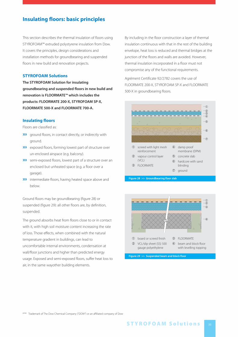
Figure 28 >> Groundbearing floor slab
➀ screed with light mesh
reinforcement
➁ vapour control layer
(VCL)
➂ FLOORMATE
➃ damp proof
membrane (DPM)
➄ concrete slab
➅ hardcore with sand
blinding
➆ ground
➃➂➁
➀
➄
➅
➆
Figure 29 >> Suspended beam and block floor
➀ board or screed finish
➁ VCL/slip sheet (SS) 500
gauge polyethylene
➂ FLOORMATE
➃ beam and block floor
with levelling topping
➃
➂➁➀
By including in the floor construction a layer of thermal
insulation continuous with that in the rest of the building
envelope, heat loss is reduced and thermal bridges at the
junction of the floors and walls are avoided. However,
thermal insulation incorporated in a floor must not
compromise any of the functional requirements.
Agrément Certificate 92/2782 covers the use of
FLOORMATE 200-X, STYROFOAM SP-X and FLOORMATE
500-X in groundbearing floors.
®™* Trademark of The Dow Chemical Company ("DOW") or an affiliated company of Dow

36
Determining the floor construction
Floors must be designed as a whole element taking
account of all the functional requirements. The position of
the insulation is influenced by the type of construction, the
predicted floor loading and the heating regime.
Buildings which are to be intermittently heated are usually
designed with ‘fast response’ fabric with the thermal
insulation on the inside of the structure. Heating systems
which utilise the structure as a heat store require the
thermal insulation to encompass as much of the structure
as possible.
The design of foundations and groundbearing floors is
influenced by the site on which the building is to be
constructed. The load bearing capacity of the soil should
be established before design work is undertaken.
Whilst a groundbearing floor is usually an effective
construction for domestic and commercial buildings,
a ground floor should be suspended in the following
circumstances:
››› domestic buildings on sloping sites where more than
600mm depth of infill would be required.
››› where the bearing capacity and nature of the ground
varies from one part to another.
››› where the ground is of shrinkable clay, expansive
material or other unstable soil type.
The site should be assessed for hazards likely to affect
substructure and groundbearing floors such as chemicals
(particularly sulphates), contaminated material above or in
the ground and waterlogged ground. In some parts of the
UK special precautions are necessary to reduce the entry of
radon gas, details of those geographical areas may be
obtained from the Department for Environment, Food and
Rural Affairs (DEFRA).
Floors must be resistant to ground hazards as outlined in
Building Regulations C1 + C2 (Standard 3.1 - 3.4 in Scotland).
Loadings
Floors should be designed to sustain safely the combined
dead and imposed loads, without excessive deflection
(Building Regulations 1991: Schedule 1 Requirement A1:
Standard 1.1 in Scotland).
In self-contained dwellings FLOORMATE ™insulation can
support the design load when:
››› sited above a groundbearing slab and covered with
suitable plywood, chipboard or screed.
››› sited below a groundbearing slab and receiving the
dead load of the slab and the loading transferred
through the slab.
››› laid on timber decking and covered with suitable
plywood or chipboard.
Load bearing internal partitions must be built off the
structural floor not the FLOORMATE insulation boards.
Internal masonry walls must have their own foundations.
For buildings other than dwellings the correct grade of
FLOORMATE insulation should be selected on the basis of
an assessment of the loading by a structural engineer.
The maximum acceptable load on FLOORMATE insulation
products is the design load together with a suitable safety
factor. (The “design load” is that load on the insulation
which will give a maximum compression of 2% after 50
years)
In the unlikely event of floor loadings being too high for an
available grade of FLOORMATE board the material may be
used as vertical edge insulation, which is not subject to
loadings from the floor slab.
Insulating floors: basic principles

37S T Y R O F O A M S o l u t i o n s
Insulating floors: basic principles
Thermal performance
Table 15 gives the thicknesses of FLOORMATE 200–X
required to achieve a range of U-values for ground floors.
Refer to BS EN ISO 6946, BS EN 13370, CIBSE Guide A and
BRE BR 443 ‘Conventions for U-value calculations’ for the
method of U-value calculation.
Heat loss from floors is concentrated at the perimeter.
Whilst an uninsulated ground floor may achieve the
required U-value the use of edge insulation will avoid
thermal bridging at the floor perimeter. FLOORMATE
boards may be installed as vertical or horizontal edge
insulation depending on the application.When used as
vertical edge insulation, FLOORMATE may be placed on the
inside of the external walls (see figure 30), within a cavity or
on the outside of the walls. Where horizontal edge insula-
tion is used beneath the slab maintain the minimum slab
thickness by setting the FLOORMATE boards into the sand
blinding or by increasing the overall depth of the slab.
Refer also to BRE document BR 262 ‘Thermal insulation:
avoiding risks’ and DEFRA/DTLR ‘Robust Details’.
Figure 30 >> Horizontal edge insulation below concrete slab
Solid ground bearing floor
P/A 0.10 0.20 0.30 0.40 0.50 0.60 0.70 0.80 0.90 1.00
U-values
0.18 25 70 90 110 110 120 120 140 140 140
0.20 25 60 80 90 100 110 110 110 120 120
0.22 - 40 70 80 90 90 100 100 100 110
0.25 - 30 50 60 70 80 80 80 90 90
No insulation 0.21 0.36 0.48 0.58 0.67 0.75 0.82 0.89 0.95 1.00
Suspended beam & block floor
P/A 0.10 0.20 0.30 0.40 0.50 0.60 0.70 0.80 0.90 1.00
U-values
0.18 50 90 110 120 120 120 140 140 140 140
0.20 30 80 90 100 100 110 110 110 110 120
0.22 25 60 80 90 90 90 100 100 100 100
0.25 25 50 60 70 80 80 80 80 90 90
No insulation 0.26 0.41 0.52 0.61 0.68 0.74 0.79 0.83 0.87 0.90
Table 15 Thickness of FLOORMATE 200-X (mm) to meet U-values (W/m2.K)
65mm Screed
65mm Screed; block 100 x 440mm, (0.51 W/mK); beam 60mm, (1.13 W/mK)

38
General description
In a groundbearing floor the ground is used to support the
floor slab for the life of the building. The floor slab is
formed:
››› with reinforced or non-reinforced concrete poured
within, but separate from the external walls, which are
built off separate foundations.
››› as a reinforced concrete raft combining both
foundation and floor.
The FLOORMATE insulation can be installed:
››› between the slab and a board finish (figure 31).
››› between the slab and the screed (figure 32).
››› below the slab (figure 33).
Positioning FLOORMATE insulation below the slab avoids
any disruption to the construction sequence. In this
position it supports the floor slab and it is essential the
insulation have sufficient compressive strength: it must also
be placed on well compacted level surface to avoid
uneven settlement.
Because of the difficulty of providing edge insulation to a
raft foundation, FLOORMATE insulation is not normally
installed below the slab in raft constructions (figure 34).
FLOORMATE insulation is designed to give the maximum
benefit in groundbearing floor construction:
››› a range of compressive strengths to match loading
conditions.
››› resistant to ground moisture.
››› thicknesses from 25mm to 100mm allow thermal
performance to be matched to project requirements.
Refer to Page 08 for the full physical and performance
properties of FLOORMATE products.
Insulating groundbearing floors: design
Figure 31 >> Insulation between the slab and a board finish
➀ floor finish e.g. carpet
➁ timber board
➂ Vapour control layer
(VCL)/Slip sheet (SS)
➃ FLOORMATE
➄ concrete slab
➅ Damp proof
membrane (DPM)
➆ hardcore with sand
blinding
➃
➂➁➀
➄
➅
➆
Figure 32 >> Insulation between the slab and the screed
➀ floor finish e.g. carpet
➁ screed with heating
elements
➂ VCL
➃ FLOORMATE
➄ concrete slab
➅ DPM
➆ hardcore with sand
blinding
➃
➂
➁
➀
➄
➅
➆
Figure 33 >> Insulation below the slab
➀ floor finish e.g. carpet
➁ screed
➂ concrete slab
incorporating heating
elements
➃ DPM
➄ FLOORMATE
➅ hardcore with sand
blinding
➃
➂
➁
➀
➄
➅

39S T Y R O F O A M S o l u t i o n s
If FLOORMATE boards are to be installed over a slab the
surface must be even (no more than 5mm deviation under
a 3m straight edge) to prevent excessive deflection of the
finished floor (refer to Agrément certificate 92/2782,
BS 8203 and BS 8204: Part 1). FLOORMATE boards should
only be laid over a slab once the building is weather tight
and should be overlaid as soon as practicable to avoid
damage from follow-on trades.
Screeds
Screeds must neither breakdown nor permit indentation of
the floor finish.
Screeds which are not monolithic with the slab should be
at least 65mm thick (75mm if heated or subject to higher
loadings) to prevent cracking and curling. They should
incorporate a light mesh (D49 to BS 4483) centrally
positioned and passing through any joints in the screed.
An unbonded screed laid over FLOORMATE boards should
be separated from the insulation by a slipsheet of 500
gauge polyethylene, well lapped and turned up at the floor
edges. Floating screeds must not bridge gaps in the layer
below.
Once laid, screeds should be covered immediately with a
polyethylene sheet to ensure a slow cure and help avoid
shrinkage cracks: the covering should be left in place for
seven days (BRE Defect Action Sheet 52).
Where screeds are heated extra care must be taken on site
to avoid failure of the heating elements and cracking of the
screed. Electric heating elements may need to be
separated from FLOORMATE products by a thickness of
screed; check with the heating system manufacturer before
specifying.
Curing/drying
Sufficient time should be allowed for the curing and drying
out of concrete slabs and screeds. Guidance is given in
BRE publication: ‘Floors and Flooring’ (Table1.3) and
BS 8203.
Insulating groundbearing floors: design
Site preparation
A bearing surface for the concrete slab should be prepared
by removing all topsoil and vegetable matter and making
up the level to the required height with inert, well graded
fill. The fill, which should pass a 150mm by 100mm screen,
should be laid and compacted in layers not exceeding
225mm to finished depths from 100mm to 600mm. Greater
depths may be used for buildings other than dwellings in
some circumstances.
The fill should be blinded with the minimum thickness
necessary to give a suitable surface for the next layer of the
construction and to protect it from being damaged by the
hard core. Sand blinding is the most suitable to receive a
sheet damp proof membrane (DPM) or FLOORMATE
boards. Blinding to receive FLOORMATE boards should be
flat and level so the boards can be laid accurately in a
continuous layer without ‘kicking up’ or rocking.
Concrete slabs
Concrete slabs should be at least 100mm thick; the need
for increased thickness and for reinforcement should be
assessed in accordance with BS 8110: Pt 1. Movement
joints in the slab should be aligned with movement joints
in other elements in the structure. A slip sheet (SS) (which
may be the DPM) must be incorporated between poured
concrete and FLOORMATE insulation.
Figure 34 >> Insulation applied over a concrete raft

40
Thermal bridging
To avoid a thermal bridge at the wall/ floor junction
continue wall insulation down to the bottom of the
concrete slab and install 25mm of FLOORMATE insulation
vertically between the edge of the slab and the inner leaf.
The exposed edge of the FLOORMATE board will normally
be hidden by the internal plaster and skirting but at
thresholds should be protected with a timber board.
Alternatively, insulating blocks may be used for the inner
leaf of the wall below floor level.
Doors in external walls require openings at floor level
which need special attention to avoid thermal bridges
(figures 35 to 37). Refer also to BRE document ‘Thermal
insulation: avoiding risks’ and DEFRA/DTLR ‘Robust Details’.
Moisture
Building Regulation C2 (Standard 3.4 in Scotland) requires
floors to resist the passage of ground moisture into the
building. Moisture can reach the interior of the building as
either ground water rising through porous construction
elements or construction water from concrete slabs or
screeds. Specific guidance is given in Approved
document C (Technical Handbook section 3.4 - Scotland).
A DPM placed above the slab and linked to the damp
proof course (DPC) will exclude ground moisture and
protect the finish against construction moisture. The
vapour control layer (VCL) must be positioned on the
warm side of the insulation.
If the DPM is positioned below the slab a separate moisture
barrier must be included above the slab to protect any
moisture sensitive floor finishes; this additional moisture
barrier will also assist the proper curing of the concrete.
When laying FLOORMATE boards over liquid applied DPMs
ensure the DPM does not contain solvents incompatible
with extruded polystyrene foam. Check with the DPM
manufacturer.
Insulating groundbearing floors: design
Figure 35 >> FLOORMATE boards above slab junction with
WALLMATE CW-X
➀ WALLMATE CW-X
➁ floor finish
➂ VCL/SS
➃ FLOORMATE
➄ DPM
➅ concrete slab
➆ hardcore with sand
blinding
➇ Damp proof course
(DPC)
➃➂➁
➀
➄
➅
➆
➇
Figure 36 >> FLOORMATE boards above slab junction with
STYROFOAM
➀ floor finish
➁ VCL/SS
➂ FLOORMATE
➃ DPM
➄ concrete slab
➅ hardcore with sand
blinding
➆ DPC
➃
➂
➁➀
➄
➅
➆
Figure 37 >> Avoiding thermal bridges at thresholds, typical
solution
➀ threshold
➁ DPC
➂ concrete slab
➃ DPM
➄ FLOORMATE
➅ hardcore with sand
blinding
➃
➂
➁
➀
➄
➅

41S T Y R O F O A M S o l u t i o n s
Insulating groundbearing floors: design
Surface water arising from conditions of use, e.g. water
carried on footwear into entrance halls or spillages in
kitchens and bathrooms can damage some flooring or
flooring panels such as chipboard. Where surface water is
likely to occur moisture resistant products or grades of
product should be used throughout the floor construction.
FLOORMATE insulation is resistant to moisture.
Services
Services such as gas and central heating pipes and
electrical cables should be run in a duct set into the screed
or the FLOORMATE boards to allow for access (figure 38).
Services should not be embedded:
››› faults are hard to find, and repair requires the floor
finish to be taken up and the screed to be broken up,
possibly damaging other services.
››› the thickness of the screed is reduced over the service,
increasing the risk of cracking.
Electrical cables less than 50mm from the underside of the
flooring panels should be protected from the floor panel’s
fixings by an earthed metallic sheath or earthed steel
conduit.
PVC-covered cables likely to come into contact with
FLOORMATE insulation should be protected by metal
or uPVC conduit or trunking to avoid the risk of
plasticiser migration from the PVC.
Water service pipes rising through a ground floor must be
adequately insulated to prevent freezing (for guidance
consult BRE document ‘Thermal insulation: avoiding risks’).
To avoid dampness entering the building the DPM must be
sealed around pipes and ducts where they pass through
the floor construction.
Underfloor heating systems
The use of warm water underfloor heating is on the
increase, for guidance refer to BS EN 1264-4: 2001 and the
Domestic Heating Compliance Guide.
Overlaying FLOORMATE with timber
As FLOORMATE boards do not provide a suitable surface for
the direct application of a floor finish: they must be
overlaid with a screed or with a timber based board.
When FLOORMATE insulation is overlaid with a board, there
is a risk of the insulation being compressed where the floor
is subjected to relatively high loads for extended periods,
possibly leading to uneven floor surfaces. Check design
load to ensure use of the correct FLOORMATE grade.
Before laying FLOORMATE boards battens should be
positioned at doorways and the foot of stairs and to
support partitions, kitchen fittings and sanitary fittings
(figure 39). The battens should be preservative treated, in
accordance with BS 5268: Part 5 (check compatibility of
preservatives with FLOORMATE insulation), and fixed to the
slab through the DPM. (Adequate time should be allowed
for preservatives to fix and for solvents from solvent based
preservatives to evaporate.)
Figure 38 >> Typical service run in floor screed
➀ floor finish
➁ access cover
➂ services
➃ pre-formed channel
set into screed
➄ VCL
➅ FLOORMATE
➃➂
➁➀
➄
➅
Figure 39 >> Additional support at thresholds
➀ door opening
➁ VCL/SS
➂ timber batten
➃ FLOORMATE
➄ DPM
➅ floor slab
➃➂➁
➀
➄
➅

42
Insulating groundbearing floors: design
Moisture resistant overlays and finishes should only be
placed once the building is weathertight. They must be
protected from damage by residual moisture in screeds
and slabs. A slipsheet (500 gauge polyethylene) should
always be laid between FLOORMATE boards and the floor
covering. A construction which is still damp when
FLOORMATE insulation and a boarded finish are to be
installed should be overlaid with an additional DPM of at
least 1200 gauge polyethylene, well lapped, sealed at joints
and turned up at edges behind skirting to protect the
flooring from construction moisture in the wall.
Timber floor finishes should be applied in accordance with
the recommendations of BS 8201. Chipboard should be to
BS 5669 Type C4 18mm thick laid with staggered cross
joints. All joints should be bonded with wood grade PVA
adhesive to avoid their squeaking in use; check the
compatibility of the adhesive with FLOORMATE insulation
prior to laying. Wedge the panels temporarily at the
perimeter until the adhesive has set.
Allow a gap of 10mm or 2mm per linear metre of flooring
(whichever is the greater) between the chipboard and the
perimeter wall. Proprietary expansion joints may be
required for uninterrupted floor runs greater than 5 metres,
the joints should allow for 2mm expansion per metre of
floor.
Where there is a likelihood of regular water spillage (e.g.
bathrooms and kitchens) the chipboard must be protected
by a waterproof covering such as continuous sheet vinyl
turned up at abutments.
For details of laying other timber overlays refer to BS 8203.
Specification
The following NBS clauses are relevant to the specification
of FLOORMATE insulation:
E20 Formwork for in situ concrete
200 Underslab sheet insulation
››› Insulation: extruded polystyrene boards
››› Thickness: 25/30/35/40/50/60/
70/75/80/90/100/120/140†mm
››› Manufacturer and reference:
Dow Chemical Co. Ltd,
Building Solutions,
2 Heathrow Boulevard,
284 Bath Road, West Drayton, Middlesex, UB7 0DQ.
Tel: 020 8917 5050 - Fax: 020 8917 5413
FLOORMATE 200-X; STYROFOAM SP-X;
FLOORMATE 500-X; FLOORMATE 700-A
Board sizes: 1250 x 600mm and 2500 x 600mm†
Edge profile: butt edge, ship lap
Compressive strength†: 200kN/m2, 350kN/m2,
500kN/m2, 700kN/m2
Design loading† : 60kN/m2, 110kN/m2, 150kN/m2,
250kN/m2
Fire classification: Reaction to fire: BS EN 13164 -
Euro class E
››› lay sheets on a level bed of sand, not less than 13mm
thick.
››› seal all joints by overlaying with 500 gauge
polyethylene with lapped joints.
››› ensure that insulation is covered with concrete
blinding (see section E10) before fixing slab
reinforcement.
† select appropriate values using STYROFOAM Solutions
Product Data - See page 09

43S T Y R O F O A M S o l u t i o n s
M10 Cement:sand/concrete screeds/toppings
290 Floating construction
››› Insulation: (as E20)
››› Thickness: (as E20)
››› Manufacturer and reference: (as E20)
FLOORMATE 200-X; STYROFOAM SP-X;
FLOORMATE 500-X; FLOORMATE 700-A
Board size: (as E20)
Edge profile: (as E20)
Compressive strength: (as E20)
Design loading: (as E20)
Fire classification: (as E20)
››› lay insulation with tight butt joints and continue up at
all abutments with walls, columns etc. for full depth of
screed.
››› lay separating layer of 500 gauge polyethylene sheet,
lapping 100mm at joints.
Insulation below screed may also be specified with clause
M13 - 260.
Insulating groundbearing floors: design
K11 Rigid sheet flooring ...
225 Particleboard floating floor
››› Base: ...
››› Preparation: ...
››› Insulation: (as E20)
››› Thickness: (as E20)
››› Manufacturer and reference: (as E20)
FLOORMATE 200-X; STYROFOAM SP-X;
FLOORMATE 500-X; FLOORMATE 700-A
Board size: (as E20)
Edge profile: (as E20)
Compressive strength: (as E20)
Design loading: (as E20)
Fire classification: (as E20)
››› Vapour control layer: ...
››› Flooring: particleboard to BS EN 312, Type P5
Thickness: ...mm
Edges: tongued and grooved all edges
Fit boards together tightly with end joints staggered.
Glue all joints.
Insulation below flooring may also be specified with:
K11 - 115/125/135/145/215/235/245,
K20 - 150/160, K21 - 120/130

44
Installation sequence FLOORMATE under slab
(figure 40)
1. Compact fill and blind with sand.
2. Fit 25mm thick FLOORMATE boards vertically at the
edges.
3. Lay FLOORMATE boards with edges tightly butted.
4. Overlay with the DPM, lapping and sealing joints. Turn
up at edges ready to link into the DPC.
5. Lay the floor slab.
Installation sequence FLOORMATE under
screed (figure 41)
1. When the concrete slab is sufficiently cured check the
surface for trueness and, if necessary blind with sand.
2. Lay FLOORMATE boards with edges tightly butted.
3. Overlay with a slip sheet with edges lapped.
4. Lay screed and leave to cure for at least seven days.
Installation sequence FLOORMATE below
timber (figure 42)
1. Lay DPM over the concrete slab.
2. Lay FLOORMATE board with edges tightly butted.
3. Overlay FLOORMATE with slipsheet with joints lapped
and edges turned up.
4. Fit flooring boards, leaving a 10mm gap at perimeters.
Key points
››› avoid point loading (eg wheelbarrows and foot traffic)
of FLOORMATE thermal insulation during installation;
provide scaffold boards or similar.
››› protect FLOORMATE boards and DPM while concreting
or screeding.
››› lay insulation over whole floor leaving no gaps.
››› stagger board joints when laying insulation in two or
more layers.
››› use temporary timber battens over perimeter walls to
protect edge insulation (if present).
››› tape joints in DPM and lap with wall DPC. Ensure DPM
is correctly positioned and continuous with DPC.
››› ensure all damp proof membranes and slip sheets are
installed and turned up correctly.
››› ensure reinforcement and installation procedures for
screeds are carried out in accordance with the
specification.
››› allow screeds to cure before any floor finishes are
applied.
››› at penetrations of the floor slab by service and soil
pipes, take care to avoid ground moisture bypassing
the DPM. Cut FLOORMATE boards to fit the
penetration closely. Fill small gaps with an expanding
polyurethane foam to form an airtight seal.
››› where services are run within a concrete slab, they
should be tested before the slab is laid.
››› keep service runs beneath the flooring to a minimum,
ensure they are accessible for maintenance. Allow a
gap of at least 10mm between timber based flooring
panels and the wall.
Insulating groundbearing floors: installation
Figure 40 >> Floormate under slab
Figure 41 >> Floormate under screed
Figure 42 >> Floormate below timber

45S T Y R O F O A M S o l u t i o n s
General considerations
Suspended floors are supported on the walls and can be
formed from:
››› timber joists and boarding.
››› cast in-situ concrete.
››› concrete beams and block infills.
››› precast concrete units.
Intermediate floors are by definition suspended and are
only required to incorporate thermal insulation if the floor
divides a heated space from an unheated space or outside
air, or when a floor slab extends to form a balcony over the
outside air.
FLOORMATE insulation is designed to give the maximum
benefit in suspended ground and intermediate floors:
››› a range of compressive strengths to match loading
conditions.
››› resistant to ground moisture.
››› thicknesses from 25mm to 100mm allow thermal
performance to be matched to project requirements.
Consult the technical data on Page 09 for the full physical
and performance properties of FLOORMATE.
Suspended ground floors of cast in-situ
concrete
Ground floor slabs may be formed in-situ onto fill which is
expected to settle and is therefore regarded merely as
temporary shuttering. In such cases the slab must be
designed and reinforced as a suspended slab even though
it is, initially, ground-bearing (figure 43). In this type of floor,
the DPM should be laid directly on the slab and then
covered by the FLOORMATE, followed by the other layers of
the floor construction.
Beam and block and precast ground floors
Beam and block floors (figure 44) and precast floors (figure
45) should be levelled ie. no more than 5mm deviation
under a 3m straight edge with a screed or grouted prior to
laying FLOORMATE boards. FLOORMATE insulation is best
applied over the beams and beneath a screed or boarded
finish.
Insulating suspended floors: design
Figure 43 >> FLOORMATE boards over cast in-situ concrete
➀ FLOORMATE
➁ DPM
➂ concrete slab
➃ hardcore with sand
blinding
➄ DPC
➃
➂
➁
➀
➄
Figure 44 >> FLOORMATE boards over beam and block floor
➀ board or screed finish
➁ VCL/SS
➂ FLOORMATE
➃ beam and block floor
with levelling topping
➃
➂
➁➀
Figure 45 >> FLOORMATE boards over precast concrete floor
➀ board or screed finish
➁ VCL/SS
➂ FLOORMATE
➃ precast floor with
levelling topping
➃
➂
➁➀

46
Suspended ground floors of timber
Timber joisted floors involve no wet trades, are simple to
install and avoid the need for large amounts of compacted
backfill. They can be insulated using FLOORMATE extruded
polystyrene in several ways:
››› between joists (figure 46).
››› attached to bottom of joists.
››› on decking (for example suitable grade of chipboard)
laid over joists.
FLOORMATE boards should not be positioned directly
onto the joists.
Insulating suspended floors: design
Figure 47 >> Exposed wall/floor junction, outer leaf supported
independently
➀ WALLMATE CW-X
➁ projecting floor
➂ FLOORMATE
➂
➁
➀
Figure 46 >> FLOORMATE boards between joists
➂
➁
➀
Thermal bridging
In suspended ground floors, as with groundbearing floors,
it is important to detail wall/floor junctions to avoid
thermal bridges.
In exposed floors, there is a risk of thermal bridging at the
wall/floor junction where the wall is built off a projecting
floor. Ensure continuity of wall and floor insulation (figure
47) or use insulating blockwork and overlapping layers of
insulation (figure 48) or insulate internally (figure 49).
Where the floor structure is timber joists, ensure the space
between the joist and the wall is packed with thermal
insulation or fix FLOORMATE boards to the underside of the
floor externally and apply a vandal proof soffit. Refer also to
BRE BR 262 ‘Thermal insulation: avoiding risks’ and
DEFRA/DTLR ‘Robust Details’.
The detailing of balconies requires careful attention to
avoid problems with thermal bridging; for guidance refer to
BRE BR 262.

47S T Y R O F O A M S o l u t i o n s
Cables run close to FLOORMATE insulation may need to be
de-rated in line with IEE Regulations. PVC-covered cables
likely to come into contact with FLOORMATE insulation
should be protected by metal or uPVC conduit or trunking
to avoid the risk of plasticiser migration from the PVC.
Specification
The following NBS clauses are relevant to the specification
of FLOORMATE insulation:
P10 Sundry insulation
255 Rigid board insulation supported between
floor joists
››› Insulation: extruded polystyrene boards
››› Thickness:
25/30/35/40/50/60/70/80/90/100/120/140† mm
†delete as appropriate
››› Manufacturer and reference:
Dow Chemical Co. Ltd,
Building Solutions,
2 Heathrow Boulevard,
284 Bath Road, West Drayton, Middlesex, UB7 0DQ.
Tel: 020 8917 5050 - Fax: 020 8917 5413
FLOORMATE 200-X
Board size: 2500mm x 600mm
Edge profile: butt edge
Compressive strength: 200kN/m2
Design loading: 60kN/m2
Fire classification:
Reaction to fire: BS EN 13164 - Euroclass E
››› Supports: saddle clips†† / nails†† / preservative treated
battens††
››› Fit tightly with closely butted joints, leaving no gaps
† select appropriate values using STYROFOAM Solutions
Product Data
†† delete as appropriate
Insulation laid on boarding may also be specified with:
K11 - 115/125/135/145/215/235/245, K20 - 150/160,
K21 - 120/130
Services
Central heating pipes are often run in the void below
suspended timber floors or within the joist depth.
When FLOORMATE boards are incorporated in the
construction, it is best to locate the pipework above the
insulation to minimise heat loss into the cold void (figure
50). The pipes should be insulated to concentrate heat
output at the radiators.
Run gas pipes below the FLOORMATE boards.
Insulating suspended floors: design
Figure 48 >> Exposed wall/floor junction, insulation applied
internally
➀ VCL/SS
➁ FLOORMATE
➂ WALLMATE CW-X
➃ DPC/tray
➃
➂
➁
➀
Figure 49 >> Exposed wall/floor junction, lightweight blockwork
inner leaf
➀ STYROFOAM LB - X
/plasterboard laminate
➁ VCL/SS
➂ FLOORMATE
➃ DPC/tray
➃
➂
➁
➀

48
Insulating suspended floors: installation
Installation sequence
Beam and block and precast floors
(figures 45 and 45)
1. Lay topping to provide necessary level surface.
2. Lay FLOORMATE boards with edges tightly butted.
3. Overlay with slip sheet with edges lapped.
4. Lay board or screed finish (allow to cure for at least
7 days).
Timber floors (figure 51)
1. Fix preservative treated battens to the sides of floor
joists so the height of the joist above the batten is the
same as the thickness of the FLOORMATE boards.
2. Cut FLOORMATE boards so they will fit tightly between
the joist and lay on the battens.
3. Lay and fix floor boards.
Key points
Beam and block and precast floors
››› refer to Key Points under Insulating groundbearing
floors: installation.
Timber floors
››› fit FLOORMATE boards tight to the underside of the
floor to avoid air movement between the FLOORMATE
boards and the floor.
››› pack FLOORMATE insulation into any spaces at the
perimeter.
››› at penetrations cut boards around the pipe or duct
and seal the gap with polyurethane foam.
››› ensure underfloor ventilation is clear and not
restricted at sleeper walls.
Figure 50 >> Services above FLOORMATE boards
Figure 51 >> FLOORMATE boards between joists

49S T Y R O F O A M S o l u t i o n s
Renovating with a concrete groundbearing
floor
When replacing an existing timber floor with a concrete
groundbearing floor follow the guidance on pages
35 - 44 of this brochure, taking account of the following:
››› fill deep sub-floor voids with hard core or a suitable
non-settling fill to a maximum depth of 600mm.
››› if the DPM cannot be tied into the DPC, it should be
dressed up behind a skirting.
››› block off ventilation openings.
FLOORMATE extruded polystyrene can also be used to
provide floor insulation in conversions, for example when
converting an agricultural building to domestic use.
Old concrete, stone or earth floors should be removed
down to a level suitable to accept the new insulated floor.
Site assessment and preparation in refurbishment projects
should follow the same procedures as for new-build.
General considerations
Improving the thermal performance of existing floors
during renovation can be desirable and economic.
Existing timber ground floors may be overlaid with
insulation and a new flooring surface.
Timber ground floors in pre-war properties often suffer
from rot and insect infestation while the underfloor void
can be a habitat for rodents. Such floors may be replaced
by a groundbearing concrete floor incorporating thermal
insulation (see figure 52).
Overlaying existing timber floors
When upgrading an existing timber floor the skirting
should be removed and the appropriate grade of
FLOORMATE laid. The flooring and finish is then laid on it.
The skirting will then be reinstalled or replaced and doors
shortened to open over the new level.
Insulating floors: renovating floors
Figure 52 >> Replacement of decaying timber floor with a new insulated concrete floor
➀ timber floor finish
➁ VCL/SS
➂ joist
➃ concrete slab
➄ DPM
➅ FLOORMATE
➆ DPC
➁➂➃
➅
➀
➄
➆

62
Agrément certificates
››› 87/1836 Pitched roofs - warm roof concept
››› 88/2105 Cavity walls
››› 92/2782 Floors
››› 97/3431 Inverted roofs
Building Regulations
››› Approved Documents to the Building Regulations
– A Structure
– B Fire safety
– C Site preparation and resistance to moisture
– E Resistance to the passage of sound
– L1A Conservation of fuel and power in new
dwellings
– L1B Conservation of fuel and power in existing
dwellings
– L2A Conservation of fuel and power in new
buildings other than dwellings
– L2B Conservation of fuel and power in existing
buildings other than dwellings
››› Technical Handbooks to Building Standards Scotland
Regulations
BRE publications
››› Thermal insulation: avoiding risks BR 262:2002.
››› Conventions for U-value calculations
– B. Anderson BR443: 2006
››› Building Elements: ‘Floors and Flooring’ – PW Pye and
HW Harris BR 332: 1997
››› Foundations, basements and external walls BR 440:
2002.
››› BRE Digest 311. Wind scour of gravel ballast on roofs.
››› BRE IP 17/01. Assessing the effects of thermal bridging
at junctions and around openings in the external
elements of buildings.
British Standards
››› BS 743: 1970: Specification for materials for damp
proof courses.
››› BS 476: Fire tests on building materials and structures.
Part 2: 1987. Methods for determination of the fire
resistance of loadbearing elements of construction.
Part 3: 1958: External fire exposure roof test
››› BS 743:1970: Specification for Materials for Damp proof
courses.
››› BS 1202: Specification for nails.
Part 1: 2002: Steel nails.
››› BS 5250: 2002: Code of practice for control of
condensation in buildings.
››› BS 5427: Code of practice for the use of profiled sheet
for roof and wall cladding on buildings.
Part 1: 1996: Design.
››› BS 5950: Structural use of steelwork in building.
Part 4: 1994 Code of practice for design of composite
slabs with profiled steel sheeting.
››› BS 5268: Structural use of timber.
Part 4: Fire resistance of timber structures.
– Section 4.2: 1990: Recommendations for calculating
fire resistance of timber stud walls and joisted floor
constructions.
Part 7: Recommendations for the calculation basis for
span tables.
– Section 7.1: 1989: Domestic floor joists.
››› BS 5502: Buildings and structures for agriculture.
Part 23: 1990: Code of practice for fire precautions.
Part 42: 1990: Code of practice for design and
construction of pig buildings.
Part 71: 1992: Code of practice for design and
construction of ventilated stores for potatoes and
onions.
››› BS 5534: 2003: Code of practice for slating and tiling.
››› BS 5628: Code of practice for use of masonry.
Part 3: 1985: Materials and components, design and
workmanship.
››› BS 6203: 1991 (1996) Guide to fire characteristics and
fire performance of expanded polystyrene materials
used in building applications.
››› BS 6229: 2003: Code of practice for flat roofs with
continuously supported coverings.
››› BS 6398: 1983: Specification for bitumen damp proof
courses for masonry.
››› BS 6399: Loading for Buildings
Part 1: 1996: Code of practice for dead and imposed
loads.
Part 2: 1997: Code of practice for wind loads.
Part 3: 1988: Code of practice for imposed roof loads.
References
63S T Y R O F O A M S o l u t i o n s
››› BS 6515: 1984 (1996) Specification for polyethylene
damp-proof courses for masonry.
››› BS 8000: Workmanship on building sites.
Part 4: 1989: Code of practice for waterproofing.
››› BS 8102: 1990: Code of practice for protection of
structures against water from the ground.
››› BS 8103 Structural Design of low-rise buildings.
Part 1: 1995: Code of practice for stability, site
investigation, foundations and ground floor slabs for
housing.
››› BS 8110: Structural use of concrete.
Part 1: 1997: Code of practice for design and
construction.
››› BS 8203: 2001 Code of practice for resilient floor
coverings.
››› BS 8204: Screeds, bases and in-situ floorings.
Part 1: 1999 Code of practice for concrete bases and
cement sand levelling screeds to receive floorings.
Part 2: 1999: Code of practice for concrete wearing
surfaces.
››› BS 8215: 1991: Code of practice for design and
installation of damp proof courses in masonry
construction.
››› BS 8218: 1998: Code of practice for mastic asphalt
roofing.
››› CP 1018: 1971 (1993) Electric floorwarming systems for
use with off-peak and similar supplies of electricity.
European standards
››› BS EN 1264: Floor heating. Systems and components.
Part 4: 2001 Installation
››› BS EN 12056: Gravity drainage systems inside
buildings.
Part 3: 2000: Roof drainage, layout and calculation.
››› BS EN 13164: 2001 Thermal insulation products for
buildings - Factory made products of extruded
polystyrene (XPS) specification.
››› BS EN 13501: Fire classification of construction
products and building elements.
Part 1: Classification using test data from reaction to
fire tests
››› BS EN 13370: 1998 Thermal performance of buildings
– Heat transfer via the ground – Calculation methods
››› BS EN 13789: 1999: Thermal performance of buildings -
Transmission heat loss coefficient - Calculation
method.
International standards
››› BS EN ISO 6946: 1997 Building components and
building elements – Thermal resistance and thermal
transmittance – Caculation method.
Other publications
››› CIBSE Guide A (1999)
››› DEFRA/DTLR Robust Details – Limiting thermal
bridging and air leakage: Robust Construction details
for dwellings and similar buildings. 2002
››› NBS Domestic Heating Compliance Guide: 2006
References

64
20
NorwichSheffield Insulations Limited,
Unit 27
White Lodge Trading Estate,
Hall Road, Norwich NR4 6DG
Tel: (01603) 765 660
Fax: (01603) 226 000
South West
BridgwaterWarren Insulation plc,
Dunball Industrial Estate,
Bridgwater, Somerset TA6 4TP
Tel: (01278) 686 000
Fax: (01278) 686 006
BristolSheffield Insulations Limited,
Riverside Business Park,
St Anne’s Road, Bristol BS4 4ED
Tel: (0117) 977 7077
Fax: (0117) 972 1172
CardiffSheffield Insulations Limited,
Unit 1 - 10, Block H & J,
South Point Foreshore Road
Cardiff CF10 4SP
Tel: (029) 2066 2900
Fax: (029) 2066 2911
PlymouthSheffield Insulations Limited,
87 St Mowden Road
Parkway Industrial Estate
Marsh Mills Plymouth
Devon PL6 8LH
Tel: (01752) 675 400
Fax: (01752) 675 419
South East
BarkingSheffield Insulations Limited,
Unit 1, New England Estate,
Gascoigne Road, Barking,
Essex IG11 7NZ
Tel: (020) 8477 9500
Fax: (020) 8477 9501
List of stockists: Uk and Ireland
Scotland
AberdeenSheffield Insulations Limited,
Broadfold Road, Bridge of Don,
Aberdeen AB23 8EE
Tel: (01224) 825 825
Fax: (01224) 822 892
Blairgowrie Sheffield Insulations Limited,
The Granary Office, Lower Mill Street,
Blairgowrie, Perthshire PH10 6AQ
Tel: (01250) 873 611
Fax: (01250) 875 252
BellshillSheffield Insulations Limited,
Righead Industrial Estate,
Bellshill, Lanarkshire ML4 3NA
Tel: (01698) 575 700
Fax: (01698) 575 701
North East
LeedsSheffield Insulations Limited,
Sussex Avenue, Leeds LS10 2LF
Tel: (0113) 385 7700
Fax: (0113) 385 7701
NewcastleSheffield Insulations Limited,
Sanderson Street,
off Scotswood Road,
Newcastle Upon Tyne NE4 7LW
Tel: (0191) 226 3110
Fax: (0191) 226 3111
SheffieldSheffield Insulations Limited,
Nunnery Drive, Sheffield S2 1TA
Tel: (0114) 241 3000
Fax: (0114) 241 3001
North WestBurscough
Sheffield Insulations Limited,
Tollgate Road, Burscough,
Lancashire L40 8LD
Tel: (01704) 898 800
Fax: (01704) 898 801
CreweWarren Insulation plc,
Marshfield Bank Employment Park,
Middlewich Road, Crewe CW2 8UY
Tel: (01270) 530 800
Fax: (01270) 530 830
ManchesterSheffield Insulations Limited,
Textilose Road, off Westinghouse Road,
Trafford Park, Manchester M17 1PY
Tel: (0161) 876 4776
Fax: (0161) 876 4775
Midlands
BirminghamSheffield Insulations Limited,
Apollo Park, Rounds Green Road,
Óldbury, Birmingham B69 2DF
Tel: (0121) 655 3050
Fax: (0121) 665 3075
ChesterfieldWarren Insulation plc,
Unit 1, Sheepbridge Centre,
Sheepbridge Lane, Chesterfield
Derbyshire S41 9RX
Tel: (01246) 450 505
Fax: (01246) 456 156
CoventryWarren Insulation plc,
Unit 2A, Longford Industrial Estate,
Bedworth Road, Coventry CV6 6BP
Tel: (024) 7664 4373
Fax: (024) 7664 4588
LoughboroughSheffield Insulations Limited,
Kernan Drive, Swingbridge Ind. Est,
Loughborough LE11 5JF
Tel: (01509) 231 891
Fax: (01509) 232 869
East
BedfordSheffield Insulations Limited,
Telford Way
Bedford MK42 0PQ
Tel: (01234) 761 100
Fax: (01234) 272 157
01
02
03
04
08
05
06
07
09
10
11
12
13
14
15
16
17
18
19
65S T Y R O F O A M S o l u t i o n s
ColchesterWarren Insulation plc,
Unit 3, 228 London Road, Marks Tey,
Colchester, Essex CO6 1EN
Tel: (01206) 214 600
Fax: (01206) 214 610
ColnbrookWarren Insulation plc,
Blackthorn Road, Poyle Trading Estate,
Colnbrook, Slough SL3 0DU
Tel: (01753) 685 131
Fax: (01753) 681 623
RuislipSheffield Insulations Limited,
Unit 4, Victoria Road Retail Park
Crown Road, South Ruislip HA4 0AF
Tel: (0208) 839 4321
Fax: (0208) 839 4301
South
SouthamptonSheffield Insulations Limited,
Unit 11, Oriana Way,
Nursling Industrial Estate,
Nursling, Southampton SO16 0YU
Tel: (023) 8074 0074
Fax: (023) 8074 0122
SouthamptonSolent Insulation Supplies,
Central Trading Estate,
Marine Parade,
Southampton SO14 5JP
Tel: (023) 8063 8796
Fax: (023) 8063 1886
TonbridgeSheffield Insulations Limited,
303 Vale Road, Tonbridge,
Kent TN9 1TZ
Tel: (01732) 370 500
Fax: (01732) 370 530
Northern Ireland
County TyroneInsulation Distributors Limited,
49 Gortin Road,
Co. Tyrone BT79 7HX
Tel: (028) 8224 6220
Fax: (028) 8224 7220
BelfastCharles Tennant and Co (NI) Ltd,
46 Ravenshill Road,
Belfast
BT6 8EB
Tel: (028) 9073 1501
Fax: (028) 9045 0927
Republic of Ireland
DublinCorcoran Products Limited,
Kingsbridge House,
17-22 Parkgate Street,
Dublin 8
Tel: 00 353 1677 8163
Fax: 00 353 1679 3521
DublinInsulation Distribution Limited,
Unit 15, Park West Industrial Park,
Nangor Road, Dublin 12
Tel: 00 353 1623 4541
Fax: 00 353 1623 4553
21
27
28
29
30
22
23
24
25
26

66
Recommendations
The STYROFOAM range of blue extruded foamed
polystyrene insulation products includes FLOORMATE,
ROOFMATE, WALLMATE and PERIMATE.
STYROFOAM products contain a flame retardant additive
to inhibit accidental ignition from a small fire source.
STYROFOAM is, however, combustible and if exposed to an
intensive fire may burn rapidly.
During shipment, storage, installation and use STYROFOAM
products should not be exposed to flames or other ignition
sources.
Fire classification is based on small-scale tests, which may
not reflect the reaction of the products in its end use state
under actual fire conditions.
STYROFOAM products should, when installed, be
adequately protected from direct exposure to fire.
Recommendations about the methods, use of materials
and construction details are given as a service to designers
and contractors. These are based on the experience of Dow
with the use of STYROFOAM products. Any drawings are
meant only to illustrate various possible applications and
should not be taken as a basis for design. Since Dow is a
materials supplier and exercises no control over the
installation of STYROFOAM products, no responsibility is
accepted for such drawings and recommendations.
In particular, no responsibility is accepted by Dow for the
systems in which STYROFOAM is used or the method of
application by which it is installed. The legal obligations of
Dow in respect of any sale of STYROFOAM products shall
be determined solely by the terms of the respective sales
contract.

67S T Y R O F O A M S o l u t i o n s
Notes
The information and data contained in this brochure do
not represent exact sales specifications. The features of the
products mentioned may vary. The information contained
in this document has been provided in good faith,
however it does not imply any liability, guarantee or
assurance of product performance. It is the purchaser’s
responsibility to determine whether these Dow products
are suitable for the application desired and to ensure that
the site of work and method of application conform with
current legislation. No licence is hereby granted for the use
of patents or other industrial or intellectual property rights.
If Dow products are purchased, we advise following the
most up-to-date suggestions and recommendations.

Dow Chemical Company Limited
Building Solutions
2 Heathrow Boulevard, 284 Bath Road
West Drayton, Middlesex UB7 0DQ
Tel: 020 8917 50 50
Fax: 020 8917 54 13
Internet: www.styrofoameurope.com
UK-291-UK-628-0305®™* Trademark of The Dow Chemical Company ("DOW")
or an affiliated company of Dow