by Carlo R. Lini and Julio A. Ramirez - pci.org Reports... · Daniel P. Jenny Research Fellowship...
111
Daniel P. Jenny Research Fellowship On the Design for Torsion of Precast/Prestressed Concrete Spandrel Girders by Carlo R. Lini and Julio A. Ramirez Purdue University School of Civil Engineering West Lafayette, IN 47907 Final Report Submitted To Precast/Prestressed Concrete Institute 209 West Jackson Boulevard Chicago, Illinois 60606-6938 June 2004 Conclusions or recommendations in this report are the opinions of the authors. PCI assumes no responsibility for the interpretation or application of the information contained herein.
Transcript of by Carlo R. Lini and Julio A. Ramirez - pci.org Reports... · Daniel P. Jenny Research Fellowship...

Daniel P. Jenny Research Fellowship
On the Design for Torsion of Precast/Prestressed Concrete SpandrelGirders
by
Carlo R. Lini and Julio A. Ramirez
Purdue UniversitySchool of Civil Engineering
West Lafayette, IN 47907
Final Report Submitted To
Precast/Prestressed Concrete Institute209 West Jackson BoulevardChicago, Illinois 60606-6938
June 2004
Conclusions or recommendations in this report are the opinions of the authors. PCI assumes no responsibility for the interpretation or application of the information contained herein.
ii
TABLE OF CONTENTS
Page
LIST OF TABLES .............................................................................................................vi
LIST OF FIGURES ..........................................................................................................vii
NOTATION ........................................................................................................................x
INTRODUCTION ..........................................................................................................1
1.1 Problem Statement .............................................................................................2
1.2 Objective ............................................................................................................3
1.3 Summary ............................................................................................................3
DESIGN FOR TORSION ...............................................................................................9
2.1 Background ........................................................................................................9
2.1.1 Noncircular Sections .........................................................................10
2.2 Skew Bending Theory ......................................................................................11
2.2.1 Transverse Steel ................................................................................12
2.2.2 Longitudinal Steel .............................................................................14
2.2.3 Minimum Longitudinal Steel .............................................................14
2.3 Thin-Walled Tube and Space Truss Analogy ..................................................16
2.3.1 Thin-Walled Tube .............................................................................16
2.3.2 Space Truss .......................................................................................17
Conclusions or recommendations in this report are the opinions of the authors. PCI assumes no responsibility for the interpretation or application of the information contained herein.

o
°oo111
Page
2.3.2.1 Transverse Steel Derivation ...............................................18
2.3.2.2 Longitudinal Steel ..............................................................19
2.3.2.3 Minimum Longitudinal Steel .............................................20
2.4 Equilibrium and Compatibility Torsion ...........................................................21
2.5 Warping Torsion ..............................................................................................22
2.6 Summary ..........................................................................................................23
EXAMINATION OF DESIGN PROCEDURES .........................................................33
3.1 Fourth Edition ..................................................................................................33
3.1.1 Critical Section ..................................................................................33
3.1.2 Threshold Torsion .............................................................................34
3.1.3 Maximum Combined Shear and Torque ...........................................35
3.1.4 Concrete Contribution .......................................................................35
3.1.5 Transverse Steel ................................................................................37
3.1.6 Longitudinal Steel .............................................................................38
3.2 Fifth Edition .....................................................................................................39
3.2.1 Concrete Contribution .......................................................................39
3.2.2 Threshold Torsion .............................................................................39
3.2.3 Cross Section ....................................................................................40
3.2.4 Transverse Steel ................................................................................40
3.2.5 Longitudinal Steel .............................................................................4l
3.3 Summary ..........................................................................................................42
Conclusions or recommendations in this report are the opinions of the authors. PCI assumes no responsibility for the interpretation or application of the information contained herein.
iv
Page
4. DESIGN EXAMPLE ....................................................................................................53
4.1 Analysis ............................................................................................................53
4.2 Adjustments .....................................................................................................54
4.2.1 Level of Prestressing .........................................................................54
4.2.2 Concrete Contribution in Shear ........................................................55
4.2.3 Depth to Compression Steel ..............................................................57
4.2.4 Summary of Adjustments .................................................................57
4.3 Required Longitudinal Steel Area ...................................................................58
4.3.1 Impact of Simplification of Ao ..........................................................58
4.3.2 Concrete Contribution .......................................................................59
4.4 Minimum Longitudinal Steel Area ..................................................................60
4.5 Threshold Torsion ............................................................................................61
4.6 Summary ..........................................................................................................61
5. PARAMETRIC STUDY ..............................................................................................76
5.1 Precast Pretensioned Spandrel .........................................................................76
5.2 Post-Tensioned Rectangular Section ...............................................................77
5.3 Comparison With Test Results ........................................................................78
5.4 Summary ..........................................................................................................79
6. SUMMARY OF FINDINGS AND CONCLUSIONS .................................................93
6.1 Findings ............................................................................................................93
6.1.1 Adjustments ......................................................................................93
6.1.2 Concrete Cover Spalling ...................................................................94
Conclusions or recommendations in this report are the opinions of the authors. PCI assumes no responsibility for the interpretation or application of the information contained herein.

v
Page
6.2 Recommendations ............................................................................................94
6.3 Future Work .....................................................................................................95
LIST OF REFERENCES ...................................................................................................96
Conclusions or recommendations in this report are the opinions of the authors. PCI assumes no responsibility for the interpretation or application of the information contained herein.
vi
Table
4.1
4.2
4.3
5.1
5.2
5.3
5.4
5.5
LIST OF TABLES
Page
Adjusted At Values ................................................................................................63
Adjusted At-~n Values ...........................................................................................63
Comparison of At Values .......................................................................................63
L Spandrel Beam ....................................................................................................80
Rectangular Section ...............................................................................................80
Comparison of Tests to Prestressed Concrete Design Procedure ..........................81
Eligible Prestressed Concrete Specimens ..............................................................82
Ineligible Prestressed Concrete Specimens ...........................................................83
Conclusions or recommendations in this report are the opinions of the authors. PCI assumes no responsibility for the interpretation or application of the information contained herein.
vii
Figure
1.1
1.2
1.3
1.4
1.5
1.6
1.7
1.8
2.1
2.2
LIST OF FIGURES
Page
Underside view of a precast/prestressed L spandrel beam. The inverted T-
beam that is resting on the spandrel beam (at midspan) creates torsion in the
restrained spandrel beam .........................................................................................5
A view from the outside shows multiple double-T beams that are resting on the
spandrel beams .........................................................................................................5
End sections of the spandrel beams appear left and right of the column. One web
is visible of the double-T beam at the end of each spandrel beam (similar to
Example 4.4.2 from the 5th Edition of the PCI Design Handbook) .........................6
Typical Spandrel Sections ........................................................................................6
Bottom Restraint of Dapped L Spandrel Beam .......................................................7
Top and Bottom Restraint of Dapped L Spandrel Beams ........................................7
Typical Detail of a Dapped L Spandrel Beam .........................................................8
Equilibrium of a Dapped L Spandrel Beam with End Restraints ............................8
Coulomb’s Device for Torsional Oscillation Tests of Thin Wires ........................25
Comparison of Coefficients ...................................................................................26
Conclusions or recommendations in this report are the opinions of the authors. PCI assumes no responsibility for the interpretation or application of the information contained herein.

viii
Figure
2.3
2.4
2.5
2.6
2.7
2.8
3.1
3.2
3.3
3.4
3.5
4.1
4.2
4.3
4.4
4.5
4.6
4.7
4.8
4.9
4.10
Page
Skew-Bending Failure Diagram ............................................................................27
Coefficient as a Function of yx/x~ ..........................................................................28
Shear and Torsion Interaction ................................................................................29
Thin-Walled Tube and Space Truss .......................................................................30
Thin-Walled Tube Derivation ................................................................................31
Space Truss Cross Section .....................................................................................32
Example of a Divided Cross Section .....................................................................44
Threshold Torsion Comparison for a Prestressed L Shaped Section .....................44
Varying Angle 0 of the Inclined Compressive Strut of the Variable Angle
Space Truss and Hoop Spacing ..............................................................................45
4th Edition Design Procedure Flow Chart ..............................................................46
5th Edition Design Procedure Flow Chart ..............................................................50
Adjustment on Required Longitudinal Steel Reinforcement .................................64
Adjustment on Av/s ................................................................................................65
Adjustment on Available At/s ...............................................................................66
Adjustment on Compressive Strut Angle ..............................................................67
Equation (4.5) and the Required Amount of Longitudinal Steel Reinforcement ..68
Comparison of Ao and 0.85 Aoh .............................................................................69
Using Equation (4.5) and the Compressive Strut Angle ........................................70
Value of Design Torsion Using 4th and 5tu Edition ................................................ 71
Shear Contribution Values for Both Editions ........................................................72
Adjustment on Minimum Longitudinal Steel Reinforcement ...............................73
Conclusions or recommendations in this report are the opinions of the authors. PCI assumes no responsibility for the interpretation or application of the information contained herein.

ix
4.8
4.9
4.10
4.11
4.12
5.1
5.2
5.3
5.4
5.5
5.6
5.7
5.8
5.9
Value of Design Torsion Using 4th and 5th Edition ................................................ 71
Shear Contribution Values for Both Editions ........................................................72
Adjustment on Minimum Longitudinal Steel Reinforcement ...............................73
Scaled Cross Sections ............................................................................................74
Threshold Torque Values Versus Scale Multiplier ................................................75
L Section Required At as a function of Strut Angle ..............................................84
L Section Required A~_min as a function of Strut Angle ......................................... 85
HSU Example Problem 5.1 ....................................................................................86
Example 5.1 Flexural Moment, Shear, and Torque Diagrams for Dead and Live
Loads ......................................................................................................................87
Rectangular Section Comparison of A~ Required for Strength ..............................88
Compressive Strut Angle .......................................................................................89
Section Example Required A~ for Strength as a Function of the Strut Angle ........90
Rectangular Section Required A~-rnin as a Function of Strut Angle ........................91
Rectangular Section (A1 5th)/(A1 4th) .................................................... 92
Conclusions or recommendations in this report are the opinions of the authors. PCI assumes no responsibility for the interpretation or application of the information contained herein.
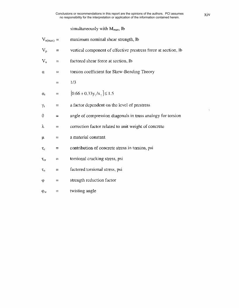
NOTATION
Acp ~
Ag =
A~ =
Ag-min =
Ao --
Aoh =
Astirrup =
At
Av --
Av-bar =
bw =
Ct =
area enclosed by outside perimeter of concrete cross section, in.2
gross area of section, in.2
total area of longitudinal reinforcement to resist torsion, in.2
minimum required area of longitudinal reinforcement to resist torsion, in.2
gross area enclosed by the center line of shear flow path, in.2
gross area enclosed by centerline of the outermost closed transverse
torsional reinforcement, in.2
area of one leg of chosen stirrup size, in2
area of one leg of a closed stirrup resisting torsion within a distance s, in.2
area of shear reinforcement within a distance s, or area of shear
reinforcement perpendicular to flexural tension reinforcement within a
distance s for deep flexural members, in.2
area of both legs of a closed stirrup, in.2
web width, or diameter of circular section, in.
torsional constant
bwd
Zx2y
Conclusions or recommendations in this report are the opinions of the authors. PCI assumes no responsibility for the interpretation or application of the information contained herein.

xi
d
fpc
fy¥
distance from extreme compression fiber to centroid of longitudinal
tension reinforcement, but need not be less than 0.8h for circular sections
and prestressed members, in.
nominal diameter of bar, wire, or prestressing strand, in.
specified compressive strength of concrete, psi
square root of specified compressive strength of concrete, psi
stress due to unfactored dead load, at extreme fiber of section where
tensile stress is caused by externally applied loads, psi.
compressive stress in concrete (after allowance for all prestress losses) at
centroid of cross section resisting externally applied loads or at junction of
web and flange, psi. (in a composite member, fpc is resultant compressive
stress at centroid of composite section, or at junction of web and flange
when the centroid lies within the flange, due to both prestress and
moments resisted by precast member acting alone)
compressive stress in concrete due to effective prestress forces only (after
allowance for all prestress losses) at extreme fiber of section where tensile
stress is caused by externally applied loads, psi
stress in the hoop, psi
maximum principal tensile stress of concrete, psi
t’t -=15 ~c
yield strength of closed transverse torsional reinforcement, psi
yield strength of longitudinal torsional reinforcement, psi
Conclusions or recommendations in this report are the opinions of the authors. PCI assumes no responsibility for the interpretation or application of the information contained herein.
xii
G
h
I
Kt
Mmax
Pcp
q
Smax
modulus of rigidity, psi
overall thickness of member, in.
moment of inertia of section resisting externally applied factored loads,
in.4
torsional stiffness
7t 02- lOfpc/f’c)
length of wire
moment causing flexural cracking at section due to externally applied
loads
(I/Yt) (6X/-~7+fp~-fa)
maximum factored moment at section due to externally applied loads, in.-
lb
outside perimeter of the concrete cross section, in.
perimeter of centerline of outermost closed transverse torsional
reinforcement, in.
shear flow, lb/in.
spacing of shear or torsion reinforcement measured in a direction parallel
to longitudinal reinforcement, in.
maximum allowable spacing, in.
torque, in-lb
nominal torsional moment strength provided by concrete, in.-lb
nominal pure torsional moment strength provided by concrete, in.-lb
Conclusions or recommendations in this report are the opinions of the authors. PCI assumes no responsibility for the interpretation or application of the information contained herein.

xiii
Wcr
Tn(max)
Tu(min)
Tu
Tv
x
Xl
y
y~
Yt
Vc
Vcr
Vu
Vo
V’c
Vci
VCW
Vd
cracking torque of concrete, in.-lb
torsional resistance provided by the horizontal forces in the hoops, in.-lb
maximum allowable torque, in.-lb
threshold torsion value, in.-lb
factored torsional moment at section, in.-lb
torsional resistance provided by the vertical forces in the hoops, in.-lb
short side of a component rectangle, in.
short side of the stirrup, in.
long side of a component rectangle, in.
long side of the stirrup, in.
distance from centroidal axis of gross section, neglecting reinforcement, to
extreme fiber in tension, in.
contribution of concrete stress in shear, psi
shear cracking stress, psi
factored shear stress, psi
nominal shear strength provided by concrete, lb
nominal pure shear strength provided by concrete, lb
nominal shear strength provided by concrete when diagonal cracking
results from combined shear and moment, lb
nominal shear strength provided by concrete when diagonal cracking
results from excessive principal tensile stress in web, lb
shear force at section due to unfactored dead load, lb
factored shear force at section due to externally applied loads occurring
Conclusions or recommendations in this report are the opinions of the authors. PCI assumes no responsibility for the interpretation or application of the information contained herein.
xiv
Vn(max) =
Up
Vu =
U~t
~tt =
0 =
)~ =
g =
"1~c
~cr
Tu ~---
q0 =
q)w =
simultaneously with Mmax, lb
maximum nominal shear strength, lb
vertical component of effective prestress force at section, lb
factored shear force at section, lb
torsion coefficient for Skew-Bending Theory
1/3
[0.66 + 0.33y1/x1 ] _< 1.5
a factor dependent on the level of prestress
angle of compression diagonals in truss analogy for torsion
correction factor related to unit weight of concrete
a material constant
contribution of concrete stress in torsion, psi
torsional cracking stress, psi
factored torsional stress, psi
strength reduction factor
twisting angle
Conclusions or recommendations in this report are the opinions of the authors. PCI assumes no responsibility for the interpretation or application of the information contained herein.
1. INTRODUCTION
A spandrel beam is an edge beam that can be subjected to large torsional moments as a
result of carrying slab, joists, and/or beams from one side. A typical precast/prestressed
concrete spandrel beam may be found in parking deck structures (Figure 1.1-1.3). Loads
applied on the ledge of an L spandrel beam result in a torsional moment due to the
eccentricity of the load with respect to the centroid of the section when it is restrained at
the ends. An advantage of using a pocket spandrel beam versus and L beam is the
reduced eccentricity of the applied load, hence a lower torque. This is shown in Figure
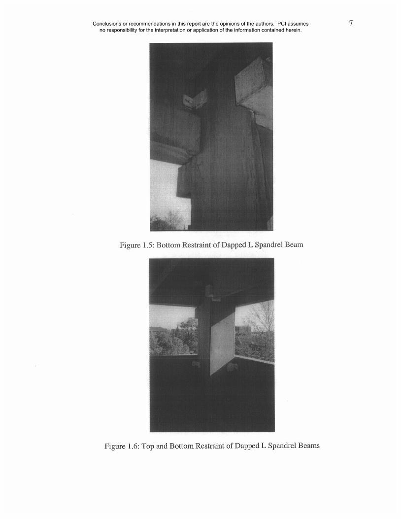
1.4. Figure 1.5 and 1.6 shows a photo of a restrained dapped L spandrel beam. A typical
detail of the spandrel to column connection for restrained dapped L spandrel beams, as
that seen in Figure 1.5 and 1.6, is shown in Figure 1.7. Figure 1.8 shows the basic
equilibrium of the dapped L spandrel beam.
In this thesis, two different design procedures for precast/prestressed spandrel
beams will be discussed. One based on the skew-bending theory and the other on a thin-
walled tube analogy prior to cracking, and a variable angle space truss analogy after
cracking. Both of these approaches have been widely used at one time or another in the
United States. Considering only equilibrium torsion (torsional moment required for
equilibrium), transverse and longitudinal reinforcement placed in a spandrel beam help it
to resist torsional moments. Depending on what design procedure is used, a concrete
contribution to the torsional strength of a reinforced/prestressed beam may also be
Conclusions or recommendations in this report are the opinions of the authors. PCI assumes no responsibility for the interpretation or application of the information contained herein.

2
included after cracking. A detailed discussion of these two design procedures is provided
in Chapters 2 and 3.
1.1 Problem Statement
Example 4.4.2 of the 4th and 5tu Edition of the PCI Design Handbook is of particular
interest. Example 4.4.2 is a shear and torsion design example of a prestressed spandrel L
beam. In the 4th Edition, the design procedure used in Example 4.4.2 is based on the
skew-bending theory. The 5th Edition uses the thin-walled tube analogy prior to cracking
and variable angle space truss analogy after cracking as the basis for design. The
examples are essentially meant to have the same design problem setup but solved with
different design procedures. However, as will be shown in Chapter 4, there are some
differences. For the same spandrel beam (the transverse steel size and spacing are also
the same) and design conditions, the 5th Edition approach resulted in a required
longitudinal area for torsional strength approximately three times greater than that from
the 4th Edition procedure. The 5th Edition approach also resulted in a minimum
longitudinal area for torsion is approximately twice as large as the result obtained with
the 4th Edition. It is important to establish the reason for the increase in the longitudinal
steel. It must be noted that the current provisions in the ACI 318-02 Code are based on a
thin-wall tube analogy prior to cracking and variable angle space truss analogy after
cracking, similar to the procedures used in the 5th Edition.
Conclusions or recommendations in this report are the opinions of the authors. PCI assumes no responsibility for the interpretation or application of the information contained herein.
3
1.2 Objective
The objective of this report is to explain the stated differences in the longitudinal
reinforcement amounts required for torsion by the skew-bending approach in the 4th
Edition of the PCI Design Handbook and the thin-walled tube and space truss analogy
procedure in the 5th Edition of the same handbook.
1.3 Summary
Two design procedures are the focus of this report, one based on the skew-bending theory,
and the other, based on the thin-walled tube analogy prior to cracking and variable angle
space truss analogy after cracking. Comparisons of both design procedures indicate that
there are differences in the longitudinal reinforcement requirements for torsion. It is
important to establish the reason for the difference in the required amounts of
reinforcement to properly establish the adequacy of both procedures. This is particularly
important since the design for torsion in the ACI 318-02 Code is based on the thin-walled
tube and variable angle space truss analogy.
Chapter 2 provides a brief history of torsion design in the United States, and
describes in greater detail, the skew-bending theory, and the thin-walled tube and variable
angle space truss approaches. The development of the design procedures based on these
theories is presented. Chapter 3 provides a comprehensive review of the design
procedures used in both the 4th and 5th Edition of the PCI Design Handbook. In Chapter
4, a comparison of Example 4.4.2 from both editions is presented. Chapter 5 will provide
results from the parametric studies conducted to establish the sensitivity of the procedures
Conclusions or recommendations in this report are the opinions of the authors. PCI assumes no responsibility for the interpretation or application of the information contained herein.
4
to various design parameters. A summary of the report and needs for further research is
given in Chapter 6.
Conclusions or recommendations in this report are the opinions of the authors. PCI assumes no responsibility for the interpretation or application of the information contained herein.
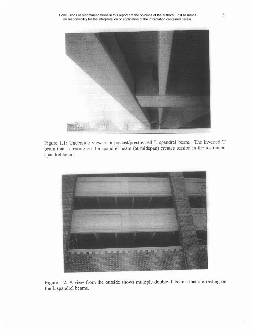
Figure 1.1: Underside view of a precast/prestressed L spandrel beam. The inverted Tbeam that is resting on the spandrel beam (at midspan) creates torsion in the restrainedspandrel beam.
Figure 1.2: A view from the outside shows multiple double-T beams that are resting onthe L spandrel beams.
Conclusions or recommendations in this report are the opinions of the authors. PCI assumes no responsibility for the interpretation or application of the information contained herein.
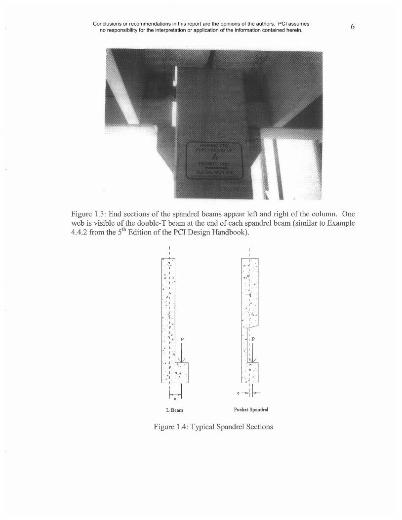
Figure 1.3" End sections of the spandrel beams appear left and right of the column. Oneweb is visible of the double-T beam at the end of each spandrel beam (similar to Example4.4.2 from the 5th Edition of the PCI Design Handbook).
L Beam Pocket Spandrel
Figure 1.4: Typical Spandrel Sections
Conclusions or recommendations in this report are the opinions of the authors. PCI assumes no responsibility for the interpretation or application of the information contained herein.
7
Figure 1.5: Bottom Restraint of Dapped L Spandrel Beam
Figure 1.6: Top and Bottom Restraint of Dapped L Spandrel Beams
Conclusions or recommendations in this report are the opinions of the authors. PCI assumes no responsibility for the interpretation or application of the information contained herein.

~B045 TYP.PSA SLOTTED INSERT(J-FINISh)
MAST]CORDLOAD BEARING SiDE
ERECTOR NOTE: CP35g CAST INTACK WELD NUT END OF SPANDRELTO "I]-IR’D. ROD OR LEDGE WHERE D.T.BURR THREADS STEM IS B" OR
LESS FROM COL.
COLUMN-TO-SPANDRELCDNNECTI:R SLEEVE W/ COVER(HIGH CONCRETE ACC,)
SECTION "C"
~’~’= (ASTU A193 GR.B7)) THREADED RODX 2’-1" Wi3,,/4"~ASTM A325] NUT, &
(1) t~, H~t_E
EP553 TYP.X 6" X 0’-6"
MI~sTICORD PAD ~W/ 1"� HOLE AND EP551 ~PLASTIC HORSESHOE SHIMS~AS REO’D
Figure 1.7: Typical Detail of a Dapped L Spandrel Beam
Figure 1.8: Equilibrium of a Dapped L Spandrel Beam with End Restraints
Conclusions or recommendations in this report are the opinions of the authors. PCI assumes no responsibility for the interpretation or application of the information contained herein.

9
2. DESIGN FOR TORSION
Chapter 2 provides a summary of the background of the design for torsion of prestressed
concrete beam sections in the United States, and provides background information on the
skew-bending theory, and the thin-walled tube and space truss analogy. Emphasis will be
placed on the connection between the theories and key design procedures. Only selected
portions of the required derivations will be provided and discussed within the context of
the approaches presented in the 4t~ and 5th Editions of the PCI Design Handbook. It must
be noted that prior to the 1995 Edition of the ACI Building Code for structural concrete
(318-95), the code was silent with respect to the design for torsion of prestressed concrete
members.
2.1 Background
In 1784, Coulomb ran a series of tests while investigating torsion. A rendition of the test
setup used is pictured in Figure 2.1. Coulomb, based on these experiments, established
the following equation to describe torque:
dw4T = i.t--~-~ ~pw (2.1)
where:
dw = diameter of the metal wire
~w = length of the wire
Conclusions or recommendations in this report are the opinions of the authors. PCI assumes no responsibility for the interpretation or application of the information contained herein.
10
g = a material constant
This equation, used to describe torsion for an elastic circular member, was not proven
theoretically until 40 years later by Navier. Based on equilibrium, compatibility and
stress-strain relationships, Navier derived the following formula (Hsu 1984):
= rp (2.2)
The material constant in Coulomb’s equation, ~t, is expressed in Navier’s equation as
(~/32)G. Therefore, Equations (2.1) and (2.2) are the same.
2.1.1 Noncircular Sections
Navier’s theoretical equation and Coulomb’s experimental equation matched. However,
problems arose when Navier derived a similar expression for torsion of noncircular
sections, or more specifically, rectangular sections. Based on tests done by Duleau six
years earlier, comparison between iron members with circular and square cross sections
expressed approximately a 20% difference between the moduli of rigidity, G (Hsu 1984).
This 20% difference, initially thought by Navier to have been caused by inconsistent
qualifies of iron, was not correctly accounted for until St. Venant’s Semi Inverse
approach. There are two general approaches to the solution of stresses in the theory of
elasticity, the direct approach and the inverse approach. St. Venant invented a "semi-
inverse" method to solve the torsion problem for noncircular cross sections (Hsu 1984).
Using this method, St. Venant derived the following expression for torsional stress of a
rectangular member:
Conclusions or recommendations in this report are the opinions of the authors. PCI assumes no responsibility for the interpretation or application of the information contained herein.
11
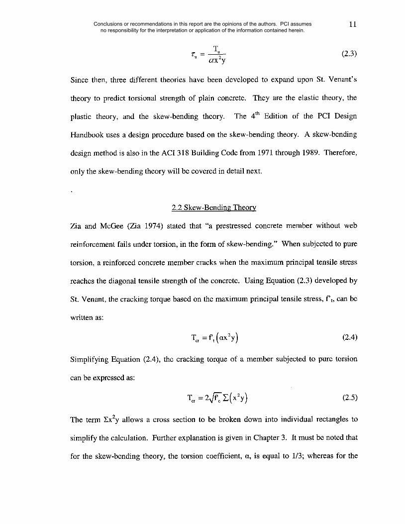
Tu (2.3)"/’u = ~x2y
Since then, three different theories have been developed to expand upon St. Venant’s
theory to predict torsional strength of plain concrete. They are the elastic theory, the
plastic theory, and the skew-bending theory. The 4th Edition of the PCI Design
Handbook uses a design procedure based on the skew-bending theory. A skew-bending
design method is also in the ACI 318 Building Code from 1971 through 1989. Therefore,
only the skew-bending theory will be covered in detail next.
2.2 Skew-Bending Theory
Zia and McGee (Zia 1974) stated that "a prestressed concrete member without web
reinforcement fails under torsion, in the form of skew-bending." When subjected to pure
torsion, a reinforced concrete member cracks when the maximum principal tensile stress
reaches the diagonal tensile strength of the concrete. Using Equation (2.3) developed by
St. Venant, the cracking torque based on the maximum principal tensile stress, f’t, can be
written as:
Tcr = f~t (~x2y) (2.4)
Simplifying Equation (2.4), the cracking torque of a member subjected to pure torsion
can be expressed as:
(2.5)
The term ZxZy allows a cross section to be broken down into individual rectangles to
simplify the calculation. Further explanation is given in Chapter 3. It must be noted that
for the skew-bending theory, the torsion coefficient, a, is equal to 113; whereas for the
Conclusions or recommendations in this report are the opinions of the authors. PCI assumes no responsibility for the interpretation or application of the information contained herein.

12
plastic and elastic theories, a varies as a function of the aspect ratio, y/x. Figure 2.2
shows a comparison of the torsion coefficient for each theory. It can be observed that
there is an almost 50% change between the elastic and fully plastic estimates depending
on increases of the y/x ratio. This observation will be revisited when discussing the role
of the concrete contribution to the torsional strength of a member in subsequent chapters.
That is for tall slender sections, cracking can significantly decrease the concrete
contribution and torsional rigidity of the section. On the other hand, spalling of the
concrete cover may not be as generalized for the same sections but concentrated at the
top and bottom of the section.
2.2.1 Transverse Steel
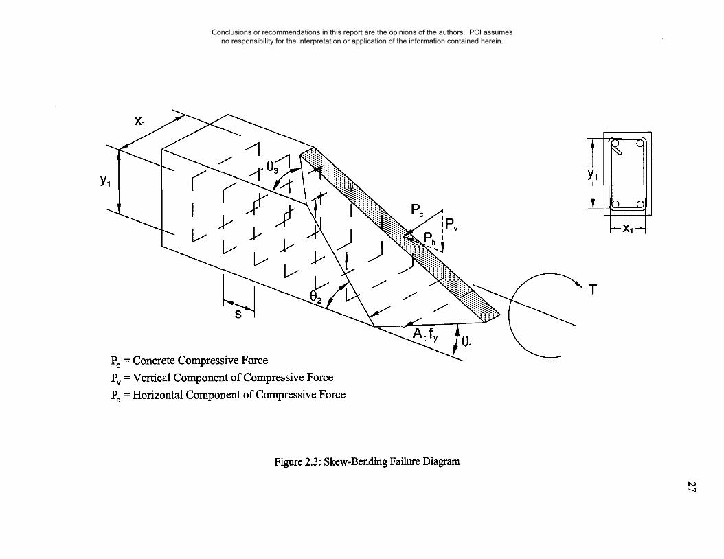
Figure 2.3 shows a skew-bending failure surface with inclined cracks on three sides and a
concrete compressive zone on the fourth side. For simplification, assume that the
member is subjected to pure torsion so that cracking angles 01 and 03 are equal. The
following expression can be written for the horizontal forces in the hoops:
Th ---- nh (Atfs) Ya (2.6)
where:
nh -- horizontal hoops crossed by the crack (Xl cot 01/s)
Equation (2.6) can be rewritten as:
Th = klAtfy (xl/yl (2.7)
where:
k~ = cot 0~ (fs/fy)
Conclusions or recommendations in this report are the opinions of the authors. PCI assumes no responsibility for the interpretation or application of the information contained herein.
13
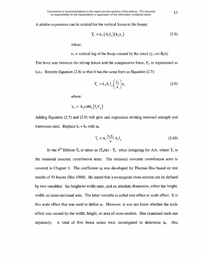
A similar expression can be created for the vertical forces in the hoops:
T, = nv (Atfs)(kzxl) (2.8)
where:
nv = vertical leg of the hoop crossed by the crack (Yl cot 02Is)
The lever arm between the stirrup forces and the compressive force, Pc, is represented as
Rewrite Equation (2.8) so that it has the same form as Equation (2.7):
where:
k3 -- k2cotO2 (fs/fy)
k2Xl.
(2.9)
Adding Equation (2.7) and (2.9) will give and expression relating torsional strength and
transverse steel. Replace kl + k3 with at.
Ts = at xlYl Atfy (2.10)s
In the 4th Edition Ts is taken as (Tu/q0) - Tc when designing for At/s, where Tc is
the torsional concrete contribution term. The torsional concrete contribution term is
covered in Chapter 3. The coefficient at was developed by Thomas Hsu based on test
results of 53 beams (Hsu 1968). He stated that a rectangular cross-section can be defined
by two variables: the height-to-width ratio, and an absolute dimension, either the height,
width, or cross-sectional area. The latter variable is called size effect or scale effect. It is
this scale effect that was used to define at. However, it was not know whether the scale
effect was caused by the width, height, or area of cross-section. Hsu examined each one
separately. A total of five beam series were investigated to determine ~t. Hsu
Conclusions or recommendations in this report are the opinions of the authors. PCI assumes no responsibility for the interpretation or application of the information contained herein.
14
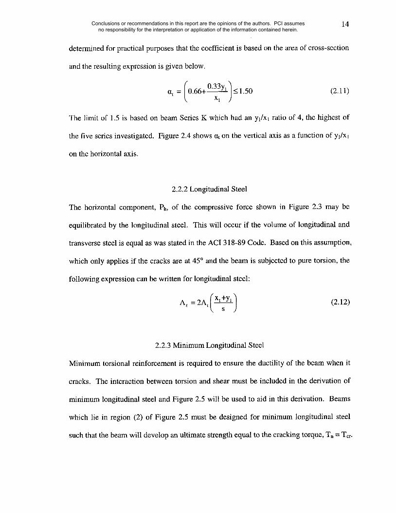
determined for practical purposes that the coefficient is based on the area of cross-section
and the resulting expression is given below.
~xt = /0.66+ 0"33Yl/< 1.50\ x~
(2.11)
The limit of 1.5 is based on beam Series K which had an yl]Xl ratio of 4, the highest of
the five series investigated. Figure 2.4 shows ~t on the vertical axis as a function of yl/Xl
on the horizontal axis.
2.2.2 Longitudinal Steel
The horizontal component, Ph, of the compressive force shown in Figure 2.3 may be
equilibrated by the longitudinal steel. This will occur if the volume of longitudinal and
transverse steel is equal as was stated in the ACI 318-89 Code. Based on this assumption,
which only applies if the cracks are at 45° and the beam is subjected to pure torsion, the
following expression can be written for longitudinal steel:
(2.12)
2.2.3 Minimum Longitudinal Steel
Minimum torsional reinforcement is required to ensure the ductility of the beam when it
cracks. The interaction between torsion and shear must be included in the derivation of
minimum longitudinal steel and Figure 2.5 will be used to aid in this derivation. Beams
which lie in region (2) of Figure 2.5 must be designed for minimum longitudinal steel
such that the beam will develop an ultimate strength equal to the cracking torque, T, = T~r.
Conclusions or recommendations in this report are the opinions of the authors. PCI assumes no responsibility for the interpretation or application of the information contained herein.

15
For a beam at point P, shear and torsion reinforcement must be provided for the stresses
(’lyr - "1¥) and (Vcr -- Vc). The torsional web reinforcement required to resist the torsional
stress is:
’lTcr -’1~c ) x2YAt-
3atXlYlfy(2.13)
Assuming at = 1.2 and x/xl = y/y~ = 1.2, Equation (2.13) can be simplified:
xsAt =-~-- E0.40 (’rcr -’to )~ (2.14)y
Shear web reinforcement required to resist the shear stress (Vcr - Vc) is ¯
bwS ,Av =--{Vcr-Vc) (2.15)
fy
Generally the height of a beam is greater than the width which allows the assumption that
bw = x for simplicity. Adding Equation (2.14) and (2.15) gives:
(2.16)
Hsu mentions that Equation (2.16) is to complicated for practical use since the stress
equations are complicated and derives the simplified equation (Hsu 1984):
200xs2At +Av-fy
(2.17)
Assume that the entire minimum web reinforcement is provided in the form of closed
stirrups allowing 2At to replace 2At+Av in Equation (2.17) which gives:
(2.18)
Conclusions or recommendations in this report are the opinions of the authors. PCI assumes no responsibility for the interpretation or application of the information contained herein.
16
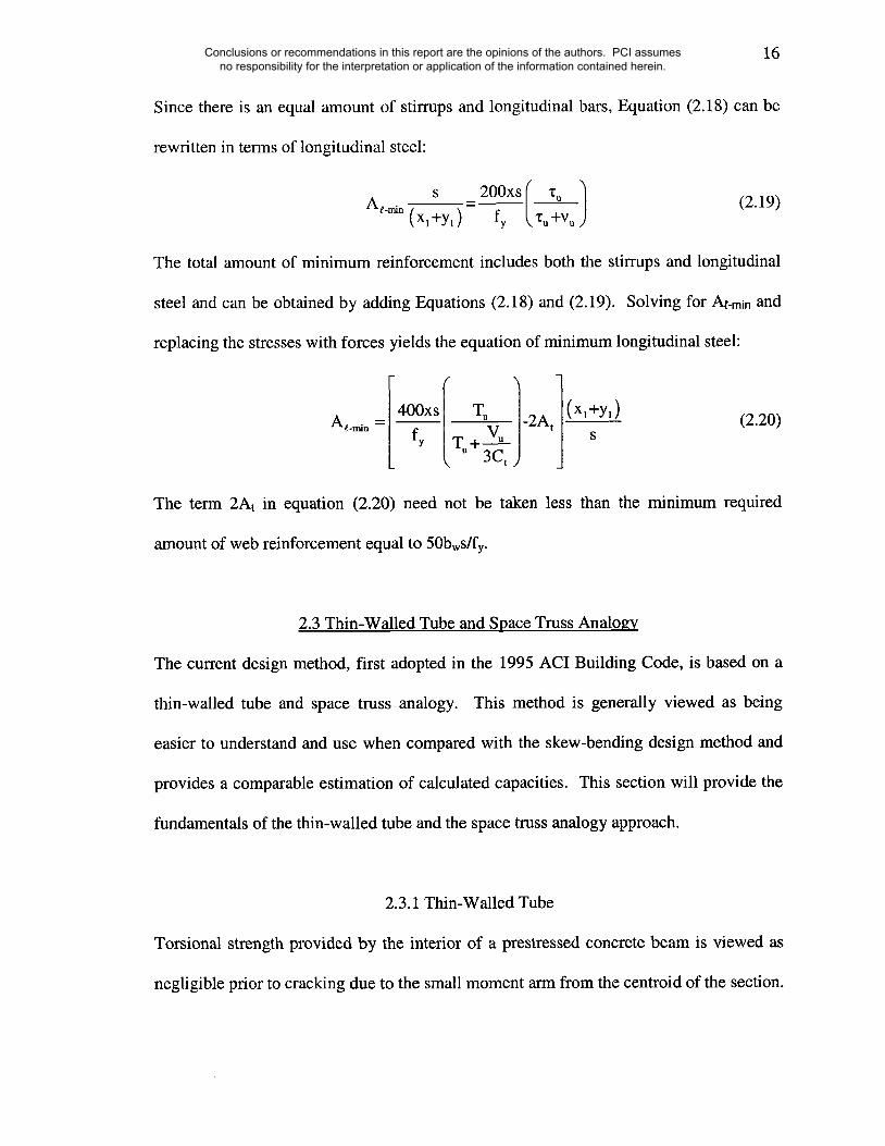
Since there is an equal amount of stirrups and longitudinal bars, Equation (2.18) can be
rewritten in terms of longitudinal steel:
s _ 200xs ( ~:z--~ (2.19)At’min (Xl +yl) fy
The total amount of minimum reinforcement includes both the stirrups and longitudinal
steel and can be obtained by adding Equations (2.18) and (2.19). Solving for !~-rnin and
replacing the stresses with forces yields the equation of minimum longitudinal steel:
3Ct ) J
The te~ 2At in equation (2.20) need not be t~en less than the ~nimum required
~ount of web reinforcement equal to 50bws/fy.
2.3 Thin-Walled Tube and Space Truss Analogy
The current design method, first adopted in the 1995 ACI Building Code, is based on a
thin-walled tube and space truss analogy. This method is generally viewed as being
easier to understand and use when compared with the skew-bending design method and
provides a comparable estimation of calculated capacities. This section will provide the
fundamentals of the thin-walled tube and the space truss analogy approach.
2.3.1 Thin-Walled Tube
Torsional strength provided by the interior of a prestressed concrete beam is viewed as
negligible prior to cracking due to the small moment arm from the centroid of the section.
Conclusions or recommendations in this report are the opinions of the authors. PCI assumes no responsibility for the interpretation or application of the information contained herein.
17
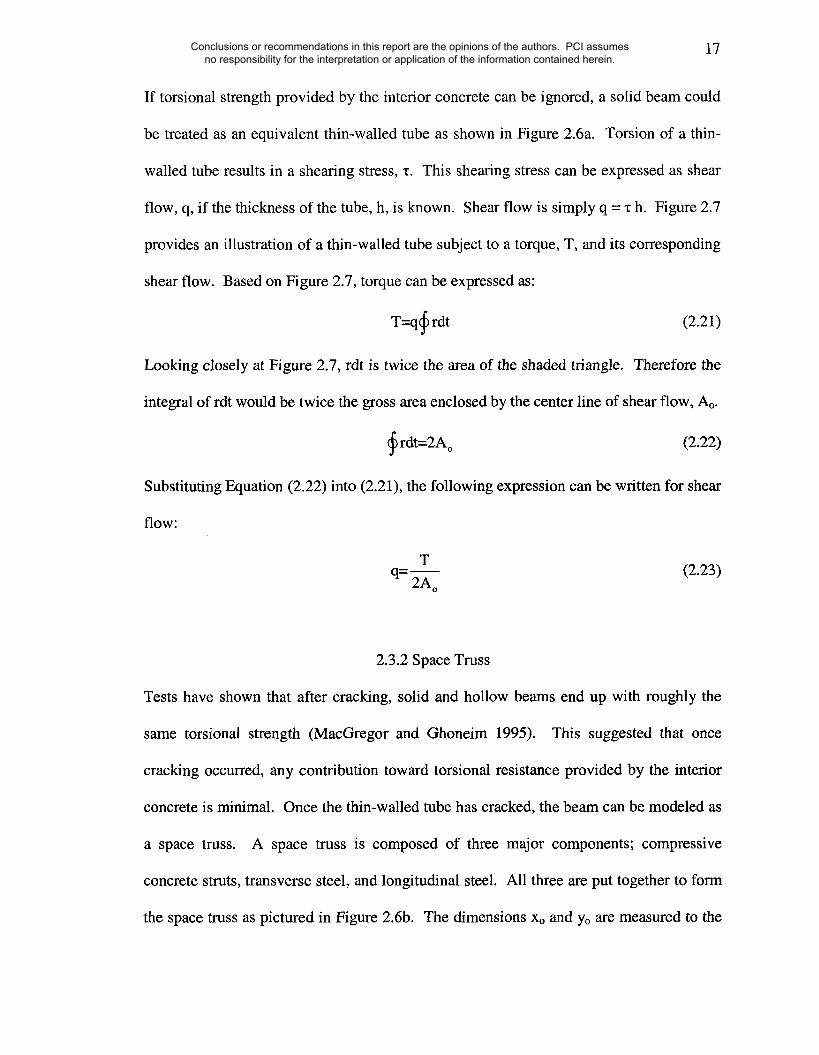
If torsional strength provided by the interior concrete can be ignored, a solid beam could
be treated as an equivalent thin-walled tube as shown in Figure 2.6a. Torsion of a thin-
walled tube results in a shearing stress, x. This shearing stress can be expressed as shear
flow, q, if the thickness of the tube, h, is known. Shear flow is simply q = "c h. Figure 2.7
provides an illustration of a thin-walled tube subject to a torque, T, and its corresponding
shear flow. Based on Figure 2.7, torque can be expressed as:
T=q~ rdt (2.21)
Looking closely at Figure 2.7, rdt is twice the area of the shaded triangle. Therefore the
integral of rdt would be twice the gross area enclosed by the center line of shear flow, Ao.
~rdt=2Ao (2.22)
Substituting Equation (2.22) into (2.21), the following expression can be written for shear
Tq=-~o
(2.23)
2.3.2 Space Truss
Tests have shown that after cracking, solid and hollow beams end up with roughly the
same torsional strength (MacGregor and Ghoneim 1995). This suggested that once
cracking occurred, any contribution toward torsional resistance provided by the interior
concrete is minimal. Once the thin-walled tube has cracked, the beam can be modeled as
a space truss. A space truss is composed of three major components; compressive
concrete struts, transverse steel, and longitudinal steel. All three are put together to form
the space truss as pictured in Figure 2.6b. The dimensions Xo and Yo are measured to the
Conclusions or recommendations in this report are the opinions of the authors. PCI assumes no responsibility for the interpretation or application of the information contained herein.
18
center of the corner bars (longitudinal reinforcement). By creating a relationship between
the space truss and the shear flow discussed in the previous section, direct equations
between the torque and the reinforcing steel can be established.
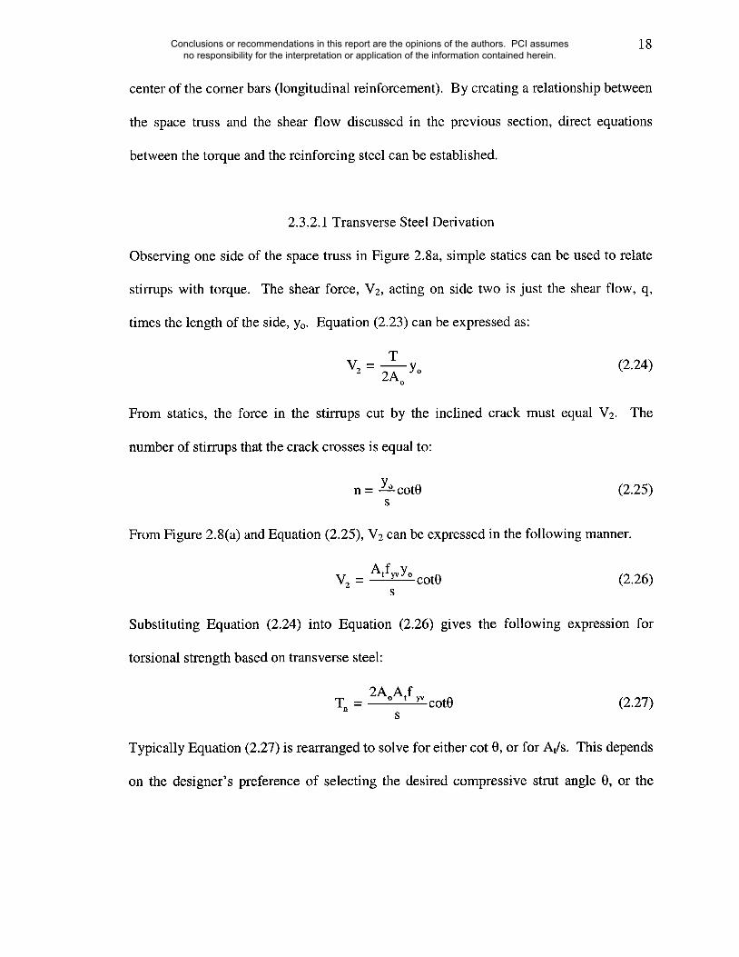
2.3.2.1 Transverse Steel Derivation
Observing one side of the space truss in Figure 2.8a, simple statics can be used to relate
stirrups with torque. The shear force, V2, acting on side two is just the shear flow, q,
times the length of the side, Yo. Equation (2.23) can be expressed as:
TV2 = ~--~oyo (2.24)
From statics, the force in the stirrups cut by the inclined crack must equal V2. The
number of stirrups that the crack crosses is equal to:
n = Y° cot0 (2.25)s
From Figure 2.8(a) and Equation (2.25), V2 can be expressed in the following manner.
Atf~YoV2 = cot0 (2.26)s
Substituting Equation (2.24) into Equation (2.26) gives the following expression for
torsional strength based on transverse steel:
2AoAIfT~ - ~ cot0 (2.27)
S
Typically Equation (2.27) is rearranged to solve for either cot 0, or for At/s. This depends
on the designer’s preference of selecting the desired compressive strut angle 0, or the
Conclusions or recommendations in this report are the opinions of the authors. PCI assumes no responsibility for the interpretation or application of the information contained herein.

19
desired size and spacing of the hoops. This flexibility in the design approach does not
exist in the 4th Edition where the compressive strut angle is always taken as 45 degrees.
2.3.2.2 Longitudinal Steel
The longitudinal steel’s contribution to torsional resistance can be derived using the same
approach used for the transverse steel. Figure 2.8b shows two sides of the space truss.
As shown in Figure 2.8b, the diagonal compressive force D2, parallel to the concrete
struts can be resolved into a shear force, V2, and an axial tension force, N2, where V2 is
expressed in equations (2.24) and (2.26). The longitudinal steel must account for the
cumulative axial tensile force N, where N can be expressed as,
N= 2(N~+N2) (2.28)
The axial tensile force on side 2 can be expressed as a function of the shearing force, V2.
A similar expression can be used for the axial tensile force on side 1.
N2 = Vzcot0 (2.29)
N~ = V~cot0 (2.30)
force can be accounted for by the longitudinal steel by summingThe total axial
horizontal components and setting them equal to A~fyt, where At equals the area of
longitudinal steel placed inside the hoops around the perimeter of the section.
Substituting Equations (2.29) and (2.30) into Equation (2.28) results in:
A~fy~ = 2( V~ +V2 )cot0 (2.31)
Conclusions or recommendations in this report are the opinions of the authors. PCI assumes no responsibility for the interpretation or application of the information contained herein.

2O
An expression similar to Equation (2.26) can be used for V1, only in this case, Xo is used
(2.31) results in ain place of Yo. Substituting these expressions into Equation
longitudinal steel equation as a function of the transverse steel, At/s.
(2.32)
If the yield strength of both reinforcements is the same, then the ratio of yield strengths,
fyv/fy~, can be taken as 1.
2.3.2.3 Minimum Longitudinal Steel
A minimum required amount of torsional reinforcement, both longitudinal and transverse
steel, is necessary in order to avoid a brittle torsional failure. To determine the minimum
required amount of torsional reinforcement, the post-cracking strength Tn will be set
equal to the cracking strength Tcr and the compressive concrete strut angle will be taking
as 45 degrees. The equation for the post-cracking torsional strength, Tn, can be obtained
from rearranging Equation (2.27):
2AoAtfy~T,- (2.33)s
The cracking torque of solid and hollow sections can be expressed by the same equation:
T==4~Ag Acp (2.34)Pep
Combining equation (2.34) and (2.33) gives:
Atf~ = 2~-~c AgAcpS (2.35)AoPcp
Conclusions or recommendations in this report are the opinions of the authors. PCI assumes no responsibility for the interpretation or application of the information contained herein.

21
In order to simplify Equation (2.35), multiply both sides by ph/s. Hsu states that "for
sizes of cross sections normally used in buildings, the ratios Acp/Ao and ph/pcp can be
taken as 1.5 and 0.83 respectively" (Hsu 1997). Simplifying Equation (2.35) gives:
Atfyv Ph =2.5~Ag(2.36)
s
Since the compressive strut angle is assumed to be 45 degrees, there must be an equal
amount of longitudinal and transverse reinforcement.
A~fye = Atf~v P-~-~ (2.37)S
Substituting Equation (2.36) into Equation (2.37) gives:
Atfre =2.5~~ Ag (2.38)
Adding Equation (2.36) and Equation (2.38) and solving for At, which represents the
minimum amount of longitudinal steel, At-min, gives:
5@Ag I~) (fyv)At-n~n = fyt - Ph ~ (2.39)
The torsional transverse steel, At/s, shall not be taken less than 25bw/fyv.
2.4 Equilibrium and Compatibility Torsion
In structures, there are two types of torsion, equilibrium torsion and compatibility torsion.
Equilibrium torsion refers to the case where the torsional moment cannot be reduced by
the redistribution of internal forces. With compatibility torsion, the torsional moment can
be reduced due to the redistribution of internal forces after cracking as it arises from
restrained deformations. The redistribution of internal forces can result from torsion
Conclusions or recommendations in this report are the opinions of the authors. PCI assumes no responsibility for the interpretation or application of the information contained herein.
22
created by the member twisting in order to maintain compatibility of deformations. For
equilibrium torsion, reinforcement must be provided to resist the total design torsional
moment as it is necessary for equilibrium of the structure. Equilibrium torsion can occur
in both statically determinate and indeterminate structures. Example 4.4.2 of the 4th and
5th Edition of the PCI Design Handbook represents a case of equilibrium torsion and
hence reinforcement is provided to resist the total design torsional moment.
Compatibility torsion only occurs in statically indeterminate structures and the current
code, ACI 318-02, allows for the reduction of the maximum factored torsional moment
for prestressed members to:
q~4~c, cp ÷ pc
~Pcp ~ 4~c’(2.40)
This allows for a reduction in the amount of torsional reinforcement required in the
spandrel beam. Equation (2.40) is the cracking torque value for a prestressed concrete
beam of a solid cross section. Equation (2.40) may also be used for hollow sections as
well. As specified in the ACI 318-02 Code, for hollow sections, Acp shall not be replaced
with Ag in Equation (2.40). Thus, the torque after redistribution is larger and hence more
conservative. This is unlike the calculation of the threshold torque for hollow sections
where Ag is used in place of Acp.
Chapter 3.
Threshold torque is discussed in greater detail in
2.5 Warping Torsion
Warping of a thin-walled, non-circular, open section generally occurs since plane
surfaces perpendicular to the longitudinal axis will not remain plane. In other words, not
Conclusions or recommendations in this report are the opinions of the authors. PCI assumes no responsibility for the interpretation or application of the information contained herein.
23
only does a particular cross section rotate, but it also deforms out of its plane. An
unrestrained L-shaped spandrel beam under an applied torque will experience some
warping. If this warping deformation is restrained by supports, diaphragms, or the
requirement of symmetry, a phenomenon called warping torsion will occur. Both
editions neglect warping torsion. Hsu has stated that "warping torsion will drastically
modify the torsional behavior and stresses of a thin-walled open section" (Hsu 1984). St.
Venant’s solution for elastic noncircular sections does account for warping of
unrestrained beams. However, if a beam were restrained creating warping torsion, an
additional normal stress in the longitudinal direction would exsist that is not accounted
for in St. Venant’s derivation that resulted in Equation (2.3) shown earlier.
For a thin-walled tube, the total differential warping displacement around the
whole perimeter of a closed section must be equal to zero. There can be no warping
torsion if there is no warping displacement. The 5th Edition of the PCI Design Handbook
is based on the thin-walled tube analogy. But the thin-walled tube analogy does not
represent the actual behavior of an L shaped spandrel beam where warping torsion in a
spandrel beam is restrained at the ends. However, this type of torsion is neglected
because the added complexity of including warping torsion is not justified on the basis of
the variability of concrete tensile strength and the actual influence of the end restraints.
2.6 Summary
Two main methods have been developed for the design for torsion of structural concrete,
one based on the skew-bending theory and the other based on the thin-walled tube and
variable angle space truss analogy. The design procedure used in the 4tr’ Edition of the
Conclusions or recommendations in this report are the opinions of the authors. PCI assumes no responsibility for the interpretation or application of the information contained herein.

24
PCI Design Handbook is based on the skew-bending theory and uses Equations (2.10),
(2.12) and (2.20) derived in this chapter. The 5th Edition design procedure is based on the
thin-walled tube prior to cracking and a variable angle space truss analogy after cracking,
and uses equations (2.27), (2.32) and (2.39). Therefore, the basis of the respective design
procedures has been established. It must be remembered that there is a significant
reduction in the torsional rigidity of the section after cracking and the contribution of the
concrete is neglected for ultimate strength considerations.
Chapter 3 provides a comprehensive review of the design procedures themselves.
In Chapter 4, the results of Example 4.4.2 from the 4th and 5t~ Edition are compared. It
will be seen that there are some differences between both procedures. Chapter 5 provides
results of the parametric studies conducted to study the influence of critical parameters in
both design procedures. Chapter 6 summarizes the report, and indicates areas of needed
research.
Conclusions or recommendations in this report are the opinions of the authors. PCI assumes no responsibility for the interpretation or application of the information contained herein.

25
(a) /
90
Figure 2.1: Coulomb’s device for torsional oscillation tests of thin wires (Hsu 1984)
Conclusions or recommendations in this report are the opinions of the authors. PCI assumes no responsibility for the interpretation or application of the information contained herein.

0.6
0.5
0.4
0.3
0.2
0.1
Nadai’s Plastic Coefficient
St. Venant’s Elastic Coefficient
5 6 7
y/xFigure 2.2 Comparison of coefficients
0.48
5O%
0.31
10
Conclusions or recommendations in this report are the opinions of the authors. PCI assumes no responsibility for the interpretation or application of the information contained herein.
Xl
Pe= Concrete Compressive ForcePv= Vertical Component of Compressive Force
Ph= Horizontal Component of Compressive Force
T
Figure 2.3: Skew-Bending Failure Diagram
Conclusions or recommendations in this report are the opinions of the authors. PCI assumes no responsibility for the interpretation or application of the information contained herein.

1.8
1.6
1.4
,q.~ 1.2
0.8
Beam Series N and G
Beam Series B ~~
’Beam Series C
Beam Series K
1 1.5 2.5 3 3.5
yl/xl
4
Figure 2.4: Coefficient as a Function of yl/xl
Conclusions or recommendations in this report are the opinions of the authors. PCI assumes no responsibility for the interpretation or application of the information contained herein.
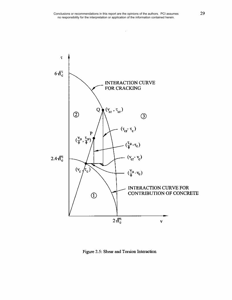
29
INTERACTION CURVEFOR CRACKING
P
INTERACTION CURVE FORCONTRIBUTION OF CONCRETE
Figure 2.5: Shear and Torsion Interaction
Conclusions or recommendations in this report are the opinions of the authors. PCI assumes no responsibility for the interpretation or application of the information contained herein.
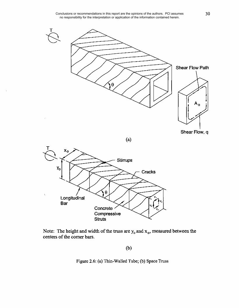
30
T
Shear Flow Path
T
Stirrups
Cracks
Shear Flow, q
LongitudinalBar
ConcreteCompressiveStruts
Note: The height and width of the truss are Yo and xo, measured between thecenters of the comer bars.
(b)
Figure 2.6: (a) Thin-Walled Tube; (b) Space Tress
Conclusions or recommendations in this report are the opinions of the authors. PCI assumes no responsibility for the interpretation or application of the information contained herein.
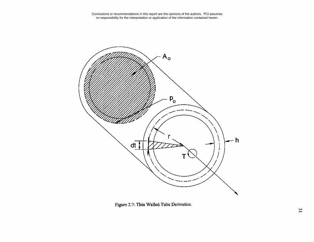
h
Figure 2.7: Thin Walled Tube Derivation
Conclusions or recommendations in this report are the opinions of the authors. PCI assumes no responsibility for the interpretation or application of the information contained herein.

32
V2 Y0
Y0
Yo cot e =I
Side 1
Side 2
N1/2
N1/2
N2/2
N~
N2/2
Note: The height and width of the truss are Yo and xo, measured between thecenters of the comer bars.
Figure 2.8: Space Tress Cross Section
Conclusions or recommendations in this report are the opinions of the authors. PCI assumes no responsibility for the interpretation or application of the information contained herein.

33
3. EXAMINATION OF DESIGN PROCEDURES
The following review of the 4th and 5th Edition procedures is provided in that order. Flow
charts for each procedure have also been provided on the basis of the example provided
in both editions of the PCI Design Handbook. In Chapter 4, a detailed comparison of the
design approaches is given.
3.1 Fourth Edition
Based on the design constraint of Example 4.4.2 in the 4th Edition of the PCI Design
Handbook, such as loading conditions, L beam sectional dimensions, compressive
strength of the concrete, yield strength of the reinforcing steel and information on the
prestressing strands, the following steps can be followed to design for torsion and shear.
3.1.1 Critical Section
From the loading conditions provided, the factored shear, Vu, and torsional moment, Tu,
at the critical section are calculated. For a prestressed member designed for shear and
torsion, the critical section can either be a distance h/2 from the face of the support or at
the face if a concentrated load or torsional moment occurs within the distance h/2. A
designer must use judgment when deciding if a load or torsional moment occurring
within 13/2 is concentrated or not.
Conclusions or recommendations in this report are the opinions of the authors. PCI assumes no responsibility for the interpretation or application of the information contained herein.

34
3.1.2 Threshold Torsion
Threshold torsion is the level of torsion above which torsional effects must begin to be
accounted for in the design. For reinforced concrete beams, this is just one-fourth of the
cracking torque of a cross-section. Equation (2.5) gives the cracking torque. For
prestressed beams, torsional cracking loads increase due to the prestress force acting on
the beam. This prestress factor is expressed
I lOf~yt= 1+~ (3.1)
f’c
As stated earlier, the threshold torsion is simply one-fourth of the cracking torque, Tcr.
Therefore, the following equation can be written for threshold torsion.
1WThreshold = q)’~ ]/t ~c Z X
2y (3.2)
The expression Xx2y can be calculated based on the dimensions of the cross section being
designed. If an L beam is being designed, then the cross section would be split up into
two rectangular sections. The x term in the expression represents the shorter dimension
of the rectangle and y, the longer. The L shaped cross section would be split such that
XxZy gives the highest attainable value. Figure 3.1 gives a simple example of two
different ways an L beam could be divided. Whichever of the two setups shown in
Figure 3.1 provide a higher y~x2y should be used. If a threshold value greater than Tu is
obtained, then torsion can be neglected. Otherwise, it must be considered in design.
Conclusions or recommendations in this report are the opinions of the authors. PCI assumes no responsibility for the interpretation or application of the information contained herein.

35
3.1.3 Maximum Combined Shear and Torque
Maximum torsional moments and shear force limits must be checked. This calculation
helps prevent compressive failure of the concrete due to over-reinforcing of the member.
That is, compressive failure before yielding of the steel reinforcement.The following
equations are for this exact purpose.
Kt)~c ~ x2y/3 (3.3)Tn(max) =Ii+(~.30CtTumtVu ./2
IOL~-~ bwd (3.4)Vn(max) ~ ]l+~30CtTu.)2
The design shear, Vu, and design torque, Tu, are not allowed to exceed maximum values
shown in Equation (3.3) and (3.4).
3.1.4 Concrete Contribution
Next is the assessment of the concrete contribution in shear Vc, and torsion Tc. By taking
into account Vc and Tc, a reduced value of the torsional moment and shear force can be
designed for. In turn, less longitudinal steel, At, will be required. If one looked strictly
at a pure torsion case, that is to say, a particular member is subjected only to a torsional
moment, the resistance of that moment provided by the concrete would act entirely
against Tu. Therefore, the entire torsional moment strength of the prestressed concrete,
T’c, can be used. A similar analogy can be used for the concrete contribution in shear,
V’c. The equations for T’c and V’~ are expressed below.
Conclusions or recommendations in this report are the opinions of the authors. PCI assumes no responsibility for the interpretation or application of the information contained herein.

T’c = 0.8)~@-c Y’,x2y(2.5Yt -1.5)
miniVowV’o =[V~i
Vcw = (3.5@-~ + 0.3fr~)bwd + Vo
Vci = 0.6@cbwd+ Vd +-ViM~rMmax
36
(3.5)
(3.6)
(3.7)
(3.8)
Since the critical section is near the support or at the face of the support, one should
expect web shear cracking to control, Vcw. Section 11.4.3 of ACI 318-02 states, "In a
pretensioned member in which the section at a distance h/2 from face of support is closer
to the end of a member than the transfer length of the prestressing steel, the reduced
pregtress shall be considered when computing Vcw." Development length of the
prestressing strand must be taking into consideration when using Equation (3.7)
When dealing with combined shear and torsional loading, T’c and V’c must be
proportioned accordingly. This can be done by using the following circular interaction:
+ -c = 1 (3.9)W’c
Assume that the ratio of shear stress to torsional stress remains constant for various loads.
This allows for the following expression:
Vc _ Vo (3.10)
Substituting Equation (3.10) into Equation (3.9) and solving for Tc and V~ gives:
Conclusions or recommendations in this report are the opinions of the authors. PCI assumes no responsibility for the interpretation or application of the information contained herein.

37
T’c (3.11)
V’c (3.12)
1+ V’c/VuT’c
From Equations (3.11) and (3.12), the shear force and torsional moment from concrete
contribution can be determined based on different levels of Tu and V,.
3.1.5 Transverse Steel
Now that the values for Tc and Vc are know, the T, and Vu values can be reduced, and the
remaining torsional moment and shear force can be used to design the transv~rse steel.
From this, the transverse area of reinforcement required by shear and torsion are
Av (Vo/ )-Vos df~
(3.13)
At _ (Tu/q0)-Wc
s atxlylfyv(3.14)
There is a minimum value for the hoop size and spacing that needs to be checked to make
sure that the ductility of the beam is adequate when it cracks. This check is made with
the following equation:
(~ 2At)> 50bwd+T)-- fy----~
(3.15)
Conclusions or recommendations in this report are the opinions of the authors. PCI assumes no responsibility for the interpretation or application of the information contained herein.

38
For the calculation of the hoop size and spacing, the designer chooses a bar size and can
then calculate the correspond spacing of the stirrups for that particular bar size. If a
different spacing is desired, a different bar size can be selected. After a bar size is
selected, the area of the bar, Av-bar, Can be used to calculate the spacing.
Av-b~ (3.16)
However, spacing of hoop for torsion must not exceed
Sin,× -- Xl + Yl < 12in. (3.17)4
The spacing of the hoops is limited to ensure the development of the ultimate torsional
strength of the beam, to prevent excessive loss of torsional stiffness after cracking, and to
control crack widths.
3.1.6 Longitudinal Steel
With the design of the transverse steel in place, the required amount of longitudinal steel,
At, can be calculated. As discussed in Chapter 2, the 4t~ Edition is based on a concrete
compressive strut angle of 45 degrees, to achieve this angle, an equal volume of
longitudinal and transverse steel must be provided. This is expressed in Equation (2.12).
After calculating At, the minimum amount of longitudinal steel, At-rain, must be checked
using Equation (2.20). Once the required amount of longitudinal steel is known, the
designer can select the number and size of the longitudinal bars to be used, so long as all
code requirements are met. The flow chart in Figure 3.4 summarizes the 4th Edition
design procedure.
Conclusions or recommendations in this report are the opinions of the authors. PCI assumes no responsibility for the interpretation or application of the information contained herein.

39
3.2 Fifth Edition
The major differences between the approaches in the 4th Edition and 5th Edition are the
varying angle as opposed to the fixed 45 degree compressive concrete strut angle and the
exclusion of the concrete contribution in torsion, Tc. Since both procedures follow a
similar path with similar equations, a much more condensed explanation will be given.
However, important parts of the design procedure will be emphasized. The design
constraints are the same in both editions of the handbook.
3.2.1 Concrete Contribution
The calculation of the contribution of concrete is simplified in this edition. Torsional
moment contributed by concrete under torsion and shear loads is neglected in the thin-
walled tube and variable angle truss analogy. As discussed in Chapter 2, resistance
provided by the interior concrete is considered minimal and neglected.
Since there is no Tc to account for, there is no shear and torsion interaction. So
essentially the shear force contributed by concrete under torsion and shear, Vc, is simply
equal to V’c, as shown in Equation (3.6). The shear reinforcement required, Av/s, can
now be calculated using Equation (3.13).
3.2.2 Threshold Torsion
The threshold torsion for the 5th Edition is slightly different from the 4th Edition.
equation to calculate the threshold torsion is:
~/I fPc
q) ~c Acp~ ~ 1 ÷ 4~-~-~TThreshold = ~c pcp
The
(3.18)
Conclusions or recommendations in this report are the opinions of the authors. PCI assumes no responsibility for the interpretation or application of the information contained herein.
40
Comparing the threshold torque values for the 4th and 5t~ Edition, the 4th Edition
threshold torque value is higher than the 5th Edition. This relationship is shown in Figure
3.2 for a prestressed L shape section. The difference between the two editions would
increase for a rectangular section having the same gross area of concrete. Threshold
torque will be explained in further detail in Chapter 5.
3.2.3 Cross Section
To ensure that the cross section is adequate, the following check is made. The
commentary of ACI 318-02, section R11.6.3.1 states that, "The size of a cross section is
limited for two reasons, first to reduce unsightly cracking and second to prevent crushing
of the surface concrete due to inclined compressive stresses due to shear and torsion."
This is achieved using the following equation for solid sections:
Vu T.p~, V~+ < q0 + 8 (3.19)1.7A o~, 2 -
For hollow sections:
(3.20)
3.2.4 Transverse Steel
The 5th Edition approach to the design of transverse steel differs from the 4th Edition. In
the 4th Edition, based on a selected bar size, the spacing of the hoop could be calculated
since the concrete compressive strut angle is held constant at 45 degrees. In the 5th
Conclusions or recommendations in this report are the opinions of the authors. PCI assumes no responsibility for the interpretation or application of the information contained herein.

41
Edition, this angle can vary between some prescribed limits. A trial bar size and spacing
is selected, and from this, the transverse steel can be calculated.
2(Ahoop leg/S)-- A v/SAt/s = (3.21)
2
After calculating At/s, the compressive concrete strut angle can be calculated.
cot0 = Tu/~P1.7Aoh (At/s)fyv (3.22)
As stated in section 11.6.3.6 of ACI 318-02, "0 shall not be taken smaller than 30 deg nor
larger than 60 deg." From Equation (3.22), At/s, is transverse steel available to resist
torsion. The ductility check expressed in Equation (3.15) is also applied in the 5th Edition.
Figure 3.3 illustrates the 5th Edition approach in further detail. It also illustrates
the important implication of allowing the concrete compressive strut angle to vary. In the
4th Edition, the angle of the concrete compressive strut is 45 degrees, therefore an equal
amount of longitudinal and transverse steel is needed. The 5th Edition allows more
flexibility in the design. For instance, a designer could decrease the number of stirrups
required to create a 45 degree compressive strut angle as is done in Figure 3.3 (b). This
in turn lowers the cracking angle and the concrete compressive strut now requires a larger
tension force for equilibrium for the same level of torsion. Conversely, steeper angles
require more hoops and reduce the tension force requirements on the longitudinal steel
(Figure 3.3 (c)).
3.2.5 Longitudinal Steel
Once the design for the transverse steel is set, the longitudinal steel requirements can be
calculated. The longitudinal steel is
Conclusions or recommendations in this report are the opinions of the authors. PCI assumes no responsibility for the interpretation or application of the information contained herein.
42
AAt = --~ phcotZ0 (3.23)
S
Equation (3.23) is essentially the same as Equation (2.32) in Chapter 2, with the ratio
fyv/fyt = 1.0. Equation (2.39) gives the minimum amount of required longitudinal steel.
The transverse steel, At/s in Equation (2.39) shall not be less than (25bw)/fy~. Where Tu
exceeds threshold torque, the minimum area of transverse closed stirrups shall be
computed by:
(Av+2At) : 0.75,f~bws < (50bwS)fyv - fr,
The flow chart in Figure 3.5 summarizes the 5th Edition design procedure.
(3.24)
3.3 Summary
The 4th Edition provides a design procedure that is based on the skew-bending theory. It
is important to note that this design procedure allows concrete contribution, To, to be
included in the torsional resistance. The 5th Edition does not include this concrete
contribution. Remember that the 5th Edition design procedure for torsion is based on the
thin-walled tube and variable angle truss analogy. It is essentially a method based on a
variable angle as opposed to the 45 degree fixed angle used in the 4th Edition. In the 4th
Edition, the amount on transverse steel needed to resist torsional moments can directly be
calculated since the angle of the concrete compressive struts (45 degrees) is known.
From this, hoop size and spacing can be determined. The 5th Edition has a different
approach. A trial size and spacing is selected for the hoops. Based on a certain level of
torsion and the hoop size and spacing selected, the concrete compressive strut angle
Conclusions or recommendations in this report are the opinions of the authors. PCI assumes no responsibility for the interpretation or application of the information contained herein.

43
would be a value that would allow for the optimization of the hoop. A lower and upper
limit of the concrete compressive strut angle is given as 30 and 60 degrees respectively.
Allowing this angle, 0, to vary between 30 and 60 degrees permits designers to optimize
the assigned amounts of hoop reinforcement. In other words, 0 will be equal to a value
that would result in the complete utilization of the hoops in both shear and torsion.
A comprehensive review of the design procedures used in the 4th and 5th Editions of the
PCI Design Handbook has been covered. Having a clear understanding of both design
procedures will help in understanding the comparison of Example 4.4.2 made Chapter 4
and the parametric studies presented in Chapter 5. A summary of the report and needs
for further research will be given in Chapter 6.
Conclusions or recommendations in this report are the opinions of the authors. PCI assumes no responsibility for the interpretation or application of the information contained herein.

44
X
Y2
X2
////////
Y2
Figure 3.1: Example of a divided cross section
400
350
300
250
200
150
100
4th Edition
10 20 30 40 50
hledg~ (in.)
60
Figure 3.2: Threshold Torsion Comparison for a Prestressed L Shaped Section
Conclusions or recommendations in this report are the opinions of the authors. PCI assumes no responsibility for the interpretation or application of the information contained herein.

45
A~1 TOTAL
S1
r.’/ A
0 = 45°
A~ TOTAL
82
,/ ../
(a)
’~ 30° < 0 < 45°
I!1>A [3 TOTAL
// / /,i /
/ / /< 0 < 60°
A~2 TOTAL > At~ TOTAL > At~ TOTAL
S2 > S1 > S3
Figure 3.3: Varying Angle 0 of the Inclined Compressive Strut of the Variable AngleSpace Truss and Hoop Spacing
Conclusions or recommendations in this report are the opinions of the authors. PCI assumes no responsibility for the interpretation or application of the information contained herein.
46
4th Edition Design Example Flow Chart
Given: f’c, fy, d and Cross Section
Calculate Tu and Vu at the critical section(At face of column or h/2)
~/~alculate developed prestress force at )
~.~ritical section, fpc.
= 41+ 10fpc/f’c I~/t
Ta~reshola = q~/t (1.5~t~,~-c)~ X 2y
Where: ~t = 1/3
Tu > TThreshold
T’c
ViMcr
V’ min Wci = 0"6~-~-~ bwd + Va -t[Vcw (3.5~f~-~ + 0.3fr.:)b w d + Vp
Neglect Torsion
Figure 3.4:4th Edition Design Procedure Flow Chart
Conclusions or recommendations in this report are the opinions of the authors. PCI assumes no responsibility for the interpretation or application of the information contained herein.
47
Kt = yt (12-10fp~/f’c)
bwdCt -- y,~x2y
Kt X~-f~ ~-’~ x 2 y/3
1 + ~30--CtT~
10~L~b ,~ d
~ Desi~ may continue if~Tu < Tn(~x) and Vu < Vn(max)
Figure 3.4:4th Edition Design Procedure Flow Chart (Continued)
Conclusions or recommendations in this report are the opinions of the authors. PCI assumes no responsibility for the interpretation or application of the information contained herein.
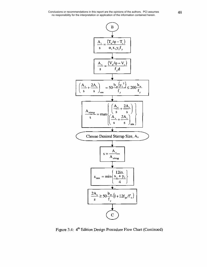
48
Figure 3.4:4th Edition Design Procedure Flow Chart (Continued)
Conclusions or recommendations in this report are the opinions of the authors. PCI assumes no responsibility for the interpretation or application of the information contained herein.
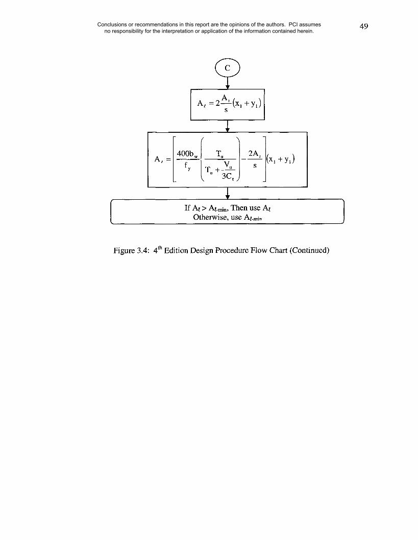
49
A, =2At (x~ +y,)S
If At > At-min, Then use AtOtherwise, use At-rain
Figure 3.4:4th Edition Design Procedure Flow Chart (Continued)
Conclusions or recommendations in this report are the opinions of the authors. PCI assumes no responsibility for the interpretation or application of the information contained herein.

50
5th Edition Design Example Flow Chart
Given: f’c, fy, d and Cross Section
Calculate Tu and Vu at the critical section(At face of column or hi2)
tViMcr
Vc = Min.Wci = 0"6~-~-~bwd + Vd -t Mm,x
[Vcw (3.5~-~ + 0.3fp~)bw d + Vp
S fyd
~//~alculate developed prestress force at ~
~.~ritical section, fpc.
T.l~reshold = q) Acp~ 1 +
Use Ag in place of Acp for hollow sections
Neglect Torsion
Figure 3.5:5th Edition Design Procedure Flow Chart
Conclusions or recommendations in this report are the opinions of the authors. PCI assumes no responsibility for the interpretation or application of the information contained herein.
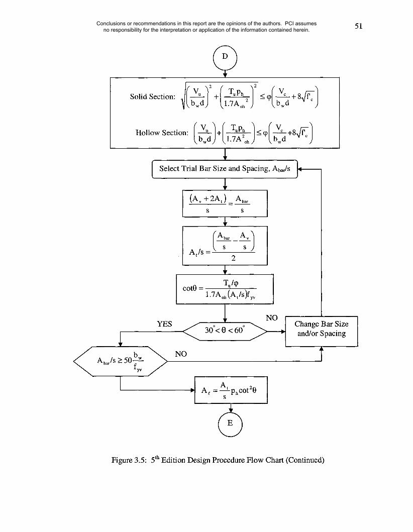
51
Solid Section:+ . T~pn:. <_q) Vc 8~c
~.l’7Aoh ) b--f-d+
Hollow Section: ~ ~’l’7A°hj_ ~bwd J
Select Trial Bar Size and Spacing, Abar/S ~-~
(Av + 2At ) _ Abar
S S
At/s = s2
cot0 = TuhP1.7Aoh (At/s)fyv
YES
A~/s>50 bw ~fyv
Change Bar Sizeand/or Spacing
Figure 3.5:5th Edition Design Procedure Flow Chart (Continued)
Conclusions or recommendations in this report are the opinions of the authors. PCI assumes no responsibility for the interpretation or application of the information contained herein.
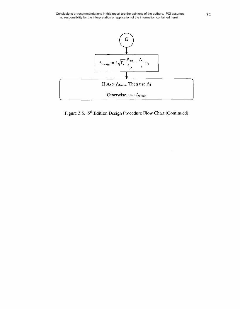
52
A~ n~n = 5~-~ Acpfy~
At
If At > At-rain, Then use At
Otherwise, use At-rain
Figure 3.5:5th Edition Design Procedure Flow Chart (Continued)
Conclusions or recommendations in this report are the opinions of the authors. PCI assumes no responsibility for the interpretation or application of the information contained herein.

53
4. DESIGN EXAMPLE
Design Example 4.4.2 of the 4th and 5th Editions of the PCI Design Handbook covers the
design for shear and torsion of the same prestressed concrete spandrel girder using two
different approaches. The difference in the area of longitudinal steel required is about
three times greater in the 5th Edition, indicating a need for a close examination of both
approaches. Some adjustments were needed in order to permit a fair comparison of both
procedueres.
4.1 Analysis
Varying the unfactored dead load provided a range in which key outcomes of the design
procedure were compared on the basis of the design problem constraints. A list of these
outcomes is summarized below:
1. Total area of longitudinal reinforcement to resist torsion, A~.
2. Minimum area of longitudinal reinforcement to resist torsion, Ag-min.
3. Transverse steel required to resist torsion, At/s.
4. Transverse steel required to resist shear, Av/s.
5. Angle of compression diagonal in truss analogy for torsion, 0, in the 5t~’
Edition approach.
A key constraint used in the PCI example is that the total amount of transverse steel for
shear and torsion, E(Av +2At )/s_~, is to be the same for both editions for the same level of
Conclusions or recommendations in this report are the opinions of the authors. PCI assumes no responsibility for the interpretation or application of the information contained herein.
54
unfactored dead load. It must be noted that this assumption directly affects the amount of
required longitudinal steel.
4.2 Adjustments
To provide a proper comparison of the design procedures used in the 4th and 5tr’ Edition,
it is important that the shear and torsion design example used in each edition be the same.
This is to ensure that any differences found in the calculated longitudinal steel values be
the result of the different theories. In the following sections, the adjustments made to
Design Example 4.4.2 of the 4th and 5th Edition of the PCI Design Handbook are
discussed in more detail.
4.2.1 Level of Prestressing
The compressive stress in the concrete, fpc, is 204 psi in the 4th Edition whereas in the 5th
Edition is 88 psi. The large difference between the two values is due to the fact that the
5th Edition has accounted for the strands as partially developed at the critical section for
torsion and shear located at h/2, while the 4tt~ Edition has not. A concentrated torque
occurs within a distance of h/2, hence the critical section in both editions is taken at the
support face, 11 inches from the beam end. It must be noted that the equation for
calculating shear strength in the 4t~ Edition adjusts the fpc value to account for transfer
length as shown in Equation (4.1). Changes in fp~ affect the shear strength, V~, which in
the 4th Edition, is equal to the controlling web shear cracking, V~w. The following
equation is used in the 4th Edition design example to calculate Vow.
Conclusions or recommendations in this report are the opinions of the authors. PCI assumes no responsibility for the interpretation or application of the information contained herein.

55
The fraction 6/50db, estimates the compressive stress at the support face which results in
a value equal to 48.9 psi, about half of the 88 psi used in the 5th Edition. The level of
prestressing in the 5th Edition is based on Section 12.9.1 of the ACI 318-02 Code.
ga=/~) db +(fps-fse) db(4.2)
The first term in Equation (4.2), (fse/3)db represents the transfer length in the strand that
would develop the prestress fse. The developed prestress in the 5th Edition is calculated
by multiplying f~e by the of the length to the critical section divided by (fs~/3)db. For this
analysis, fpc was changed to 48.9 psi in the 5t~’ Edition. This change had no impact on the
required longitudinal steel for the 5~ Edition and only affected the threshold torque value.
The threshold torque value, originally equal to 183 kip-in., after this modification is 173
kip-in, for the 5tr’ Edition compared to 226 kip-in, in the 4tr~ Edition. The difference in the
threshold torque values is discussed in Section 4.5.
4.2.2 Concrete Contribution in Shear
There is a discrepancy between the two editions related to the shear strength, Vc.
Equation (4.1) shows that V~ is equal to Vow in the 4th Edition, since web shear cracking
In the 5th Edition, Ve was taken as:
Vc = 2,f~-~-~ bw d
controlled at the end region.
(4.3)
This results in a much lower value for V~, 81.5 kips versus 157.8 kips used in the 4th
Edition. In the direct comparison of the 4th and 5th Edition results, the same concrete
Conclusions or recommendations in this report are the opinions of the authors. PCI assumes no responsibility for the interpretation or application of the information contained herein.

56
contribution in shear is used for both editions. Equation (4.3) represents the shear
strength provided by concrete for nonprestressed members. A more appropriate
representation of the web shear cracking mechanism observed at end regions of
prestressed concrete beams such as that being designed in the 5th Edition example.
Therefore, the controlling Vow will be used in both examples.
Using Vow significantly reduces the required amount of longitudinal steel in the
5th Edition as shown Figure 4.1. Figure 4.1 shows the required longitudinal steel, A~, on
the vertical axis for different levels of unfactored dead load shown on the horizontal axis.
The vertical dashed line at an unfactored dead load of 89.5 psf represented the value used
in both editions of the handbook. Arrows depicting the change in the required amount of
longitudinal steel due to Vcw have been placed in the figure. By increasing the concrete
contribution resisting shear, Vc, in the 5th Edition, less transverse steel is needed for shear
resistance, Avis, as seen in Equation (3.13). This decrease in Avis is also displayed in
Figure 4.2. Figure 4.2 also displays the unfactored dead load on the horizontal axis. The
required amount of transverse steel reinforcement for shear, A,,/s is plotted on the vertical
axis. Since the same total amount of transverse reinforcement, /(Av +2At )/s~, is used in
both editions, if Avis decreases as shown in Figure 4.2, then the amount of transverse
reinforcement available to resist torsion, At/s, should increase for the given amount of
total transverse steel. This increase in the available amount is shown in Figure 4.3. In
this figure, the available amount of transverse steel reinforcement for torsion, At/s, is
plotted on the vertical axis versus unfactored dead load on the horizontal axis. An
increase in the available At/s for the same unfactored dead load will result in an increase
in the concrete compressive strut angle required to resist torsion, 0, seen in Equation
Conclusions or recommendations in this report are the opinions of the authors. PCI assumes no responsibility for the interpretation or application of the information contained herein.

57
(3.21) and in Figure 4.4. Figure 4.4 plots the concrete compressive strut angle, 0, on the
vertical axis versus unfactored dead load on the horizontal axis. The concrete
compressive strut angle is equal to 32.7° prior to the adjustment to Vc, and 41° after the
adjustment was made for a value of unfactored dead load of 89.5 psf. The increase in 0
results in a decrease in At. Equation (3.23) shows the 5th Edition calculation for At.
Therefore, by using the appropriate equation to represent concrete contribution in shear,
Vow, in the 5th Edition, less longitudinal steel reinforcement is required to resist the same
level of torsion as more transverse steel reinforcement is available to resist from the total
used in both examples.
4.2.3 Depth to Compression Steel
The distance from the extreme compression fiber to the centroid of longitudinal tension
reinforcement, d, was taken as 72 inches in the 5th Edition and 69 inches in the 4th Edition.
For the purpose of comparing both editions, 69 inches was used in place of 72 inches in
the 5th Edition design example. This adjustment has very little impact on the required
longitudinal steel in the 5th Edition example.
4.2.4 Summary of Adjustments
The use of V~w instead of Vc in the 5th Edition had the greatest impact of the three
adjustments, as it decreased the required longitudinal steel values in the 5th Edition.
Table 4.1 summarizes the results of all three adjustments.
Conclusions or recommendations in this report are the opinions of the authors. PCI assumes no responsibility for the interpretation or application of the information contained herein.

58
4.3 Required Longitudinal Steel Area
After all necessary adjustments to Example 4.4.2 of the 4th and 5th Edition of the PCI
Design Handbook have been made; the comparison between the two approaches indicates
that there are two key items leading to the stated differences in A~:
1. The simplification of the lever arm area, Ao = 0.85Aoh, in Equation (3.22)
2. Concrete Contribution Term, Tc
4.3.1 Impact of Simplification of Ao
In Section 11.6.3.6 of the ACI 318-02 Code, it is stated that "Ao shall be determined by
analysis except that it shall be permitted to take Ao equal to 0.85Aoh."
A° = 0.85Aoh
(4.4)
Equation (4.4) over-estimates the amount of concrete spalling of tall slender sections
since spalling will occur near the top and bottom of the section. This over-estimation in
spalling will result in a greater amount of reinforcing steel for torsion. The ACI 318-02
Code also states in Commentary Section R11.6.3.6 that, "The expression for Ao given by
HSU11.32 may be used if greater accuracy is desired." Hsu (Hsu 1997) noted that Equation
(4.4) may "under-estimate the torsional strength of lightly reinforced small members by
up to 40 percent and over-estimate the torsional strength of heavily reinforced large
The following expression was proposed by Hsu:
2TupcpAo = Aop- q)f~A~p
members by up to 20 percent."
(4.5)
Using Equation (4.5), the term 1.7Aoh in Equation (3.22) is replaced with 2Ao which
gives the following expression for calculating the compressive concrete strut angle:
Conclusions or recommendations in this report are the opinions of the authors. PCI assumes no responsibility for the interpretation or application of the information contained herein.

59
cot0 = T,/q~ (4.6)2Ao (A,/s)f~
Using Equation (4.6) with the procedure in the 5th Edition results in a required
longitudinal steel amount of 1.33 in.z, similar to the value obtained using the 4th Edition.
Table 4.3 shows the comparison between the 4t~ and 5t~ Edition values for At using
Equation (4.6). The difference in At is plotted in Figure 4.5 for various values of
unfactored dead load. Figure 4.6 shows the large difference between Equation (4.4) and
(4.5). Using Equation (4.5) also affects the compressive strut angle as shown in Figure
4.7, and it is this change in the compressive strut angle that causes the decrease in
Using Equation (4.5) in the 5t~ Edition results in comparable At values to those obtained
using the 4t~ Edition approach.
4.3.2 Concrete Contribution
Another important factor in the difference between A~ values in the 4t~ and 5th Edition
examples is the concrete contribution, To. Since the 4t~ Edition includes concrete
contribution in torsion, a shear and torsion interaction must be used. As can be seen in
Figure 4.8, the amount of torsion to be designed for increases at about the same rate in
both editions suggesting that At/s for both editions should increase at the same rate.
However, the 5t~ Edition design procedure will require less transverse reinforcement for
shear, Av/s, than the 4t~ Edition. This is the result of using a larger concrete contribution
in shear in the 5t~ Edition than in the 4t~ Edition, since there is no shear and torsion
interaction in the 5tr’ Edition. Figure 4.9 shows the concrete contribution in shear for both
the 4th and 5th Edition along with the design value for shear, Vu. From Equation (3.13)
Conclusions or recommendations in this report are the opinions of the authors. PCI assumes no responsibility for the interpretation or application of the information contained herein.

60
and the use of Figure 4.9, as the unfactored dead load increases, the Av/s term for the 4th
Edition increases while none is required for the 5th Edition. Since the total amount of
transverse reinforcement is kept the same between both editions, the At/s value from the
5th Edition is increasing at a greater rate than the At/s value from the 4th Edition. This
results in an increase in the cracking angle and a decrease in the rate of required amount
of longitudinal steel, ,44.
4.4 Minimum Longitudinal Steel Area
Initially, the values for the minimum amount of longitudinal steel reinforcement, At-min,
also differed significantly. The 5th Edition approximately required double the amount of
minimtun longitudinal steel reinforcement when compared to the 4th Edition. However,
unlike the required longitudinal steel reinforcement for strength, the initial difference in
the minimum values, A~-min, between both editions appears to mainly be a result of the
discrepancy in the shear concrete contribution reviewed in Section 4.4.2. Figure 4.10
shows the result of changing Vc in the 5th Edition to Vow. As the unfactored dead load
increases, the minimum amount of longitudinal steel is decreasing due to the increase in
transverse steel to resist torsion, At/s. From Figure 4.8, the 4th and 5t~ Edition approach
provide similar minimum longitudinal
both initial and adjusted A~-min values.
steel reinforcement values. Table 4.2 provides
Since more or less At/s can be used so long as the
cracking angle remains between 30 and 60 degrees, the amount of A~_min can vary in the
5th Edition depending on what cracking angle or hoop size and spacing is desired.
Conclusions or recommendations in this report are the opinions of the authors. PCI assumes no responsibility for the interpretation or application of the information contained herein.

61
4.5 Threshold Torsion
The adjusted threshold values from the 4th and 5th Edition of the PCI Design Handbook
are 199 kip-in, and 173.3 kip-in, respectively. The adjustments of fpc described earlier
only affected the 5th Edition threshold torque value which originally was 183.3 kip-in.
This change was a result of using 48.9 psi as the compressive stress, fpc, instead of 88 psi.
The 4th Edition uses an fpc value based on fully developed prestressing and the 5th Edition
uses an fpc that is accounted for development length. An fpc value of 48.9 psi was used in
the 4th Edition and accounts for the decrease in the threshold torque value to 199 kip-in.
Equation (3.2) and (3.18) are used to calculate the threshold torque values in the 4th
Edition. The threshold torque obtained from the 4th Edition is higher than that obtained
from the 5th Edition, but the difference is not significant. A model was set up in which
the L-shaped cross section from Example 4.4.2 of the PCI Design Handbook was scaled
to provide different cross sections while still maintaining the original shape. Figure 4.11
provides an example of how the cross sections were scaled. Threshold torsion values
were calculated for each scaled cross section and the results were used to generate Figure
4.12. It can be seen from Figure 4.12 that both editions provide similar threshold torsion
levels. The 4th Edition results in slightly higher, but comparable threshold torsion values
in comparison to the 5th Edition results for L shaped spandrel sections.
4.6 Summary
The initial difference between the 4th and 5th Edition values for the amount of
longitudinal steel can be considerably less if the same estimate of V~ is used in both
editions. Use Vcw and V~i where permitted in place of the minimum value of 2@b,~d
Conclusions or recommendations in this report are the opinions of the authors. PCI assumes no responsibility for the interpretation or application of the information contained herein.
62
for the nominal shear strength provided by the concrete. Even after Example 4.4.2 of the
PCI Design Handbook was adjusted in both editions, so the 5th Edition still required
larger amounts of longitudinal steel compared to the 4th Edition. This can be attributed to
the assumption behind Equation (4.4) regarding the amount of concrete cover spalling
compared to Equation (4.5). Using Equation (4.5) in the 5th Edition resulted in similar
results for longitudinal steel for strength. Furthermore, threshold torque values were also
similar in both approaches. Differences found in the required A~ value for strength, after
all adjustments including the use of Equation (4.5), were attributed to the concrete
contribution term for torsion and the resulting shear and torsion interaction in the 4th
Edition which reduced the concrete contribution in shear. Chapter 5 will present the
results of parametric studies conducted to further examine differences between both
procedures. Chapter 6 summarizes the findings of the study and indicates areas of
needed research.
Conclusions or recommendations in this report are the opinions of the authors. PCI assumes no responsibility for the interpretation or application of the information contained herein.

63
Table 4.1: Adjusted A~ Values
Initial Values Adjusted Values
4th Edition
5th Edition
% Difference
1.58 in2
4.96 in2
214%
1.59 in2
3.65 inz
130%
Table 4.2: Adjusted A~
Initial Values
4th Edition 1.10 in2
5th Edition 2.03 in2
% Difference 85%
Table 4.3:Comparison of A~ Values
Eq. (4.4) Eq. (4.5)
4th Edition 1.59 in2 1.59 in2
5th Edition 3.65 in2 1.33 inz
% Difference 130% 19%
-rain ValuesAdjusted Values
1.09 in2
1.29 in2
18%
Conclusions or recommendations in this report are the opinions of the authors. PCI assumes no responsibility for the interpretation or application of the information contained herein.
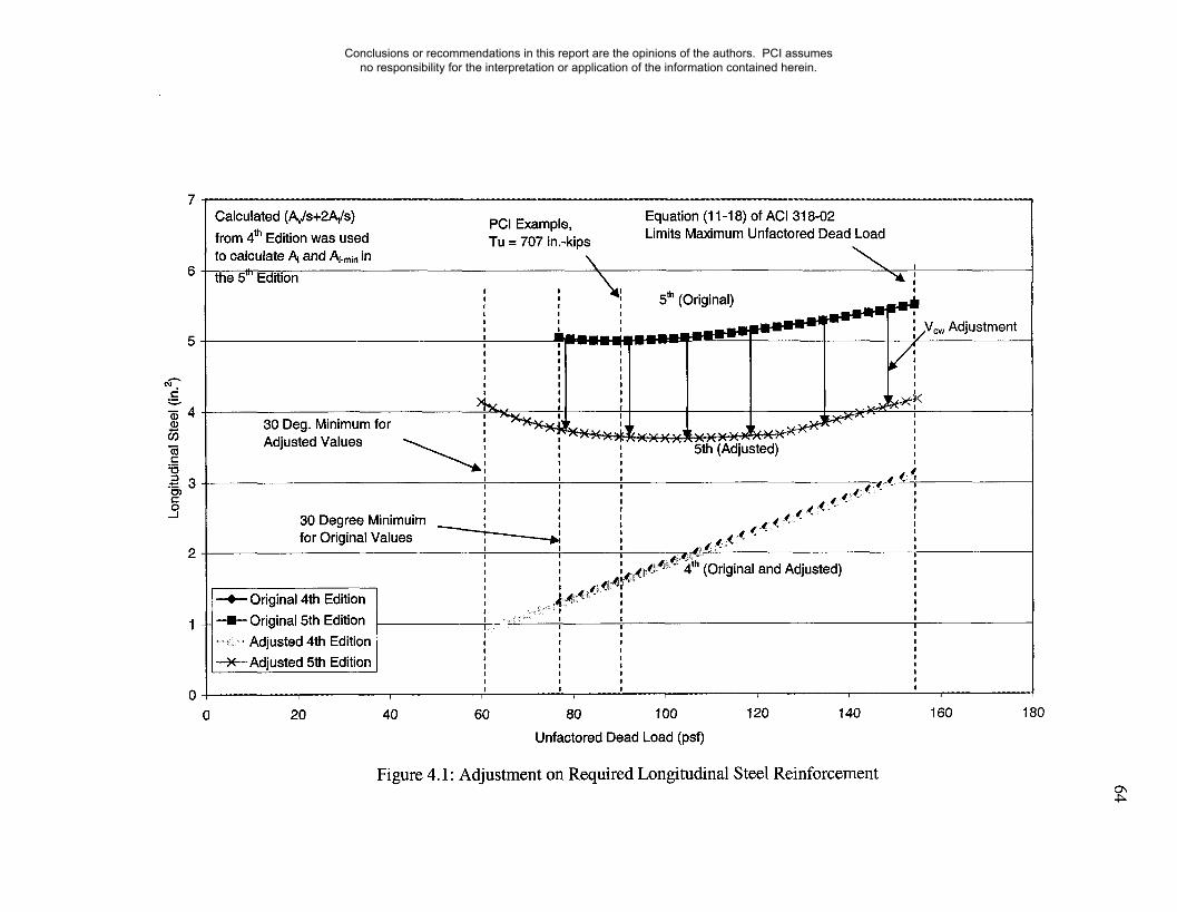
Calculated (A~/s+2A~/s)from 4th Edition was usedto calculate/~ and Al.min in
the 5"’ Edition
PCI Example, Equation (11-18) of ACI 318-02Limits Maximum Unfactored Dead LoadTu = 707 in.-kips
" " " 5th (Original)~,,, , , ,
, , ,
.~l~ll~~~1~1 -",I.V Ad, u ,
., , , stment
30 Degree Minimuim ’, t ’,for Original Values
, ,~,~,.~,: ....... 4 (Original and Adjusted) ,
+ Ongtnal 4th Edition ~1’, :’~" ,-!--Original 5th Edition............... Adjusted 4th Edition~ Adjusted 5th Edition ’
20 40 60 80 100 120 140 160
Unfactored Dead Load (psf)
180
Figure 4.1: Adjustment on Required Longitudinal Steel Reinforcement
Conclusions or recommendations in this report are the opinions of the authors. PCI assumes no responsibility for the interpretation or application of the information contained herein.
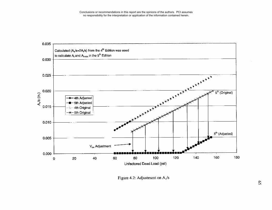
0.035
0.030
0.025
0.020
0.015
0.010
0.005
0.000
Calculated (A~/s+2A~/s) from the 4th Edition was usedto calculate AI and Ai.min in the 5th Edition
0
+ 4th Adjusted+ 5th Adjusted......... 4th Original---x-- 5th Original
V~ Adjustment
40
~~ .~,~ 5t~ (Original)
.... ~’ .~~
5th (Adjusted)
60 80 100 120 140 160 180
Unfactored Dead Load (psf)
Figure 4.2: Adjustment on Av/s
Conclusions or recommendations in this report are the opinions of the authors. PCI assumes no responsibility for the interpretation or application of the information contained herein.
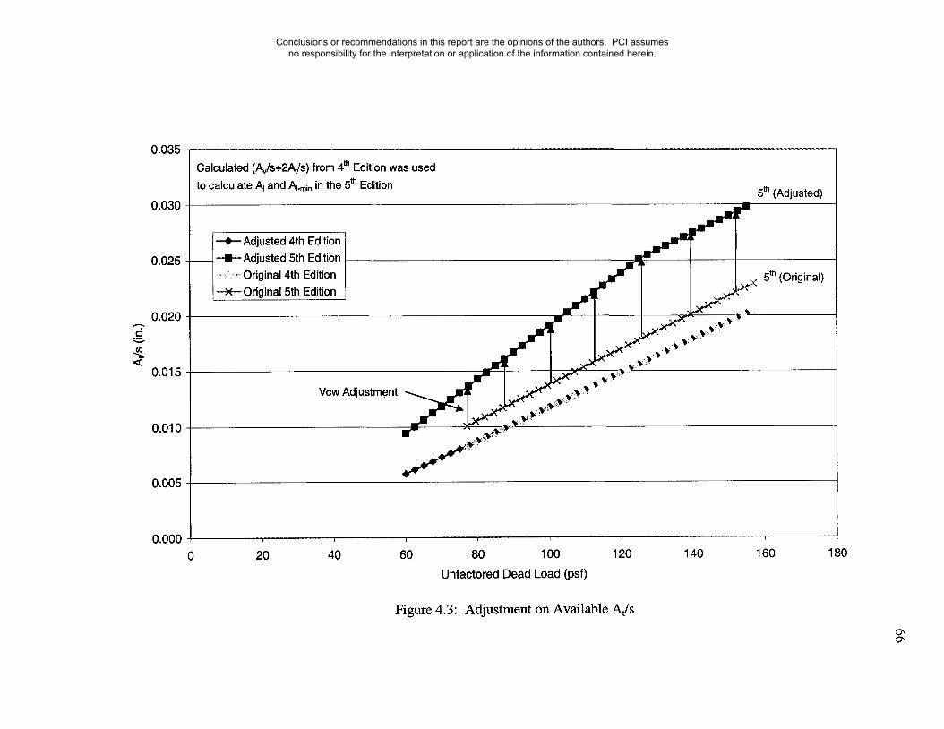
0.035
0.030
0.025
0.020
0.015
0.010
0.005
0.000
Calculated (,~,/s+2At/s) from 4th Edition was usedto calculate A~ and Ai.min in the 5th Edition 5th (Adjusted)
i--e--Adjusted 4th Edition~Adjusted 5th Edition....... :,,,,, Original 4th Edition
---X--Original 5th Edition
Vow Adjustment
(Original)
20 40 60 80 100 120 140
Unfactored Dead Load (psf)
160 18O
Figure 4.3: Adjustment on Available At/s
Conclusions or recommendations in this report are the opinions of the authors. PCI assumes no responsibility for the interpretation or application of the information contained herein.
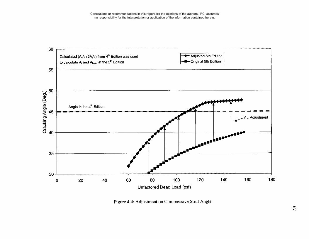
60
55
35
30
Calculated (Av/s+2A~/s) from 4th Edition was used
to calculate/~ and ~-r~in in the 5th Edition
-’~"Adjusted 5th Edition
Original 5th Edition
0
Angle in the 4~h Edition
20 40
Adjustment
60 80 100 120 140 160 180
Unfactored Dead Load (psf)
Figure 4.4: Adjustment on Compressive Strut Angle
Conclusions or recommendations in this report are the opinions of the authors. PCI assumes no responsibility for the interpretation or application of the information contained herein.
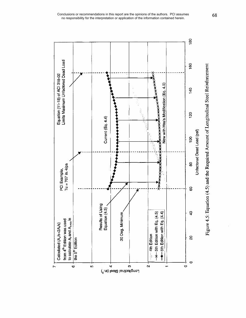
68
0 -~hi-
(~’u!) lee.l.S leu!pn~.!6uo"l
0
o
o
oo
Conclusions or recommendations in this report are the opinions of the authors. PCI assumes no responsibility for the interpretation or application of the information contained herein.

69Conclusions or recommendations in this report are the opinions of the authors. PCI assumes no responsibility for the interpretation or application of the information contained herein.
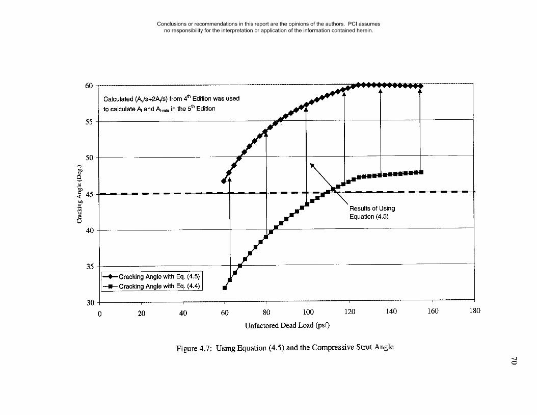
6O
55
5O
45
4O
35
3O
Calculated (A~/s+2A~/s) from 4t" Edition was usedto calculate/~ and Ai.min in the 5th Edition
--,i’--Cracking Angle with Eq. (4.5)--I--Cracking Angle with Eq. (4.4)
20 40 60 80 100 120 140 160
Unfactored Dead Load (psf)
180
Figure 4.7: Using Equation (4.5) and the Compressive Strut Angle
Conclusions or recommendations in this report are the opinions of the authors. PCI assumes no responsibility for the interpretation or application of the information contained herein.

1200
1100
1000
900
8OO
700
600
5OO
400
300
200
100
0
--*--Tn-Tc (4th Edition)
~Tn (5th Edition)
Tc (4th Edition)
_.....--
_.....--
mn 5th Edition
0 20 40 60 80 100 120 140
Unfactored Dead Load (psf)
160 180
Figure 4.8: Value of Design Torsion Using 4t~ and 5t~ Editions
Conclusions or recommendations in this report are the opinions of the authors. PCI assumes no responsibility for the interpretation or application of the information contained herein.

200
150
100
50
0
~ Vu (4th & 5th Edition)
~ Vow (4th & 5th Edition)............. , Vc (4th Edition)
Vow
Me
20 40 60 80 100 120 140
Unfactored Dead Load (psf)
160 180
Figure 4.9: Shear Contribution Values for Both Editions
Conclusions or recommendations in this report are the opinions of the authors. PCI assumes no responsibility for the interpretation or application of the information contained herein.

7
6
5
4
3
2
Calculated (Av/s+2A~/s)
from 4th Edition was usedto calculate/~ and Ai.min in
the 5m Edition
PCI Example,Tu = 707 in.-kips
30 Deg. Minimum foAdjusted Values
30 Degree Minimuimfor Original Values
+Original 4th Edition
--I--Original 5th Edition....... Adjusted 4th Edition
--X--Adjusted 5th Edition
,,
Equation (11-18) of ACl 318-02Limits Maximum UnfactoredDead Load
Vc,, Adiustment !,
0 20 40 60 80 100 120 140 160
Unfactored Dead Load (psf)
180
Figure 4.10: Adjustment on Minimum Longitudinal Steel Reinforcement
Conclusions or recommendations in this report are the opinions of the authors. PCI assumes no responsibility for the interpretation or application of the information contained herein.

Conclusions or recommendations in this report are the opinions of the authors. PCI assumes no responsibility for the interpretation or application of the information contained herein.

30O
250
5O
00.6
--X---5th Edition L-Spandrel Design Example
0.7 0.8 0.9 1 1.1
Scale Multiplier
Figure: 4.12: Threshold Torque Values Versus Scale Multiplier
1.2
Conclusions or recommendations in this report are the opinions of the authors. PCI assumes no responsibility for the interpretation or application of the information contained herein.

76
5. PARAMETRIC STUDY
Chapter 5 provides results of further studies using two design examples featuring
rectangular and L beam sections to help verify the findings in Chapter 4. It should be
noted that both examples represents cases of equilibrium torsion. The previous chapter
established that with some modifications, the 5th Edition could result in similar amounts
of required longitudinal steel reinforcement as those obtained using the approach in the
4th Edition of the handbook. Finally, a comparison of test data versus calculated values
from the report entitled "Evaluation of Design Procedures for Torsion in Reinforced and
Prestressed Concrete," (Ghoneim 1993) will be provided at the end of this chapter.
5.1 Precast Pretensioned Spandrel
Additional analysis was preformed on the design example in the 4t~ and 5th Edition of the
PCI Design Handbook studying the effect of using different strut angles in the 5th Edition
design procedure. First the spandrel beam is designed using the 4t~ Edition design
procedure. It is important to note that adjustments made in the previous chapter are also
included here. There are a total of four different designs carried out using the 5tr~ Edition
design approach. One in which the transverse steel is kept the same, and three additional
designs based on compressive concrete strut angle values of 30, 45, and 60 degrees. The
results of these designs are shown in Table 5.1 and represent values for a section located
at the face of the .support. It can be seen from Table 5.1 that the 5tr~ Edition consistently
Conclusions or recommendations in this report are the opinions of the authors. PCI assumes no responsibility for the interpretation or application of the information contained herein.

77
provides similar amounts of reinforcement as the 4th Edition approach. The required
longitudinal steel values shown in Table 5.1 can be reduced using 6-1/2 in. diameter,
270K strands, since there is no moment at the supports. The strand is only assigned the
capacity to develop 60 ksi at the support face as per Section 11.6.3.10 in the ACI 318-02
Code. Figure 5.1 and 5.2 show the strength and minimum requirements for longitudinal
steel for various values of unfactored dead load. From Table 5.1, Figure 5.1 and 5.2, it
can be summarized that for PCI Design Example 4.4.2, the 5th Edition procedure results
in similar amounts of reinforcement.
5.2 Post-Tensioned Rectangular Section
The next design example studied was taken from the book entitled "Torsion of
Reinforced Concrete" (Hsu, 1984). It consists of a post-tensioned, rectangular beam
section under shear and torsion. This example was chosen to illustrate the results of the
two approaches in the case of a rectangular cross and compare the findings with those of
the L shaped spandrel beam. Figure 5.3 provides an illustration of the design constraints
and Figure 5.4 gives the moment, shear, and torque diagrams. For continuous beams,
negative moments at the supports must be accounted for if prestressing steel is to be used
to resist torsion at the critical section. The negative moment reduces the prestressing
steel stress at the critical section.
example, Vci controls and not Vow.
It should also be noted that unlike the PCI design
The web-shear cracking region is smaller for a beam
near a continuous support and larger near a simple support. Results of this analysis have
been placed in Table 5.2. Once again, the 5th Edition design procedure provides similar
design values as those obtained with the 4t~ Edition approach.
Conclusions or recommendations in this report are the opinions of the authors. PCI assumes no responsibility for the interpretation or application of the information contained herein.

78
Figure 5.5 shows the positive affect of using Equation (4.5) on the required longitudinal
steel values for strength. The results shown in Figure 5.5 are based on the enforcement of
the same amount of transverse reinforcement in the 4th and 5th Edition approaches. The
calculated strut angle in the 5th Edition, where the total amount of transverse
reinforcement is the same between both editions, is shown in Figure 5.6. The minimum
required longitudinal steel values for various dead load levels as a function of the strut
angle are shown in Figure 5.7 and 5.8. As was the case for the L-shaped spandrel beam,
when using Equation (4.5), the 5t~ Edition design procedure provided similar results as
those of the 4t~ Edition approach.
5.3 Comparison With Test Results
In Ghoneim and MacGregor (1993), test data was gathered and used to compare test
versus calculated capacities obtained with what is now the current design procedure for
torsion of prestressed concrete in the ACI 318-02 Code. In this report, no comparison
was made between the 4th and 5th Edition design procedures. In this section, the 5th
Edition comparison was done twice, once using Equation (4.4) and a second time using
Equation (4.5). The ratio obtained using the approach in the 4th Edition is also included
in Table 5.3. Table 5.3 summarizes the results, and Tables 5.4 and 5.5 provide the test
versus calculated torsion values for each individual beam. Some beams were not
included from the original report because the authors were not able to reproduce the
calculated values provided in the report. Furthermore, the beams listed in Table 5.4 are
considered eligible beams whereas the beams in Table 5.5 are ineligible for because they
do not meet the ACI Code requirement for stirrups spacing; hence, these beams were not
Conclusions or recommendations in this report are the opinions of the authors. PCI assumes no responsibility for the interpretation or application of the information contained herein.
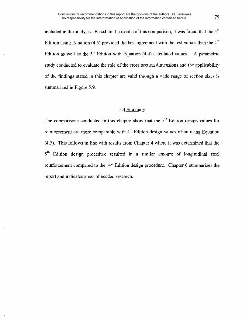
79
included in the analysis. Based on the results of this comparison, it was found that the 5th
Edition using Equation (4.5) provided the best agreement with the test values than the 4t~
Edition as well as the 5t~ Edition with Equation (4.4) calculated values. A parametric
study conducted to evaluate the role of the cross section dimensions and the applicability
of the findings stated in this chapter are valid through a wide range of section sizes is
summarized in Figure 5.9.
5.4 Summary
The comparisons conducted in this chapter show that the 5th Edition design values for
reinforcement are more comparable with 4th Edition design values when using Equation
(4.5). This follows in line with results from Chapter 4 where it was determined that the
5th Edition design procedure resulted in a similar amount of longitudinal steel
reinforcement compared to the 4th Edition design procedure. Chapter 6 summarizes the
report and indicates areas of needed research.
Conclusions or recommendations in this report are the opinions of the authors. PCI assumes no responsibility for the interpretation or application of the information contained herein.
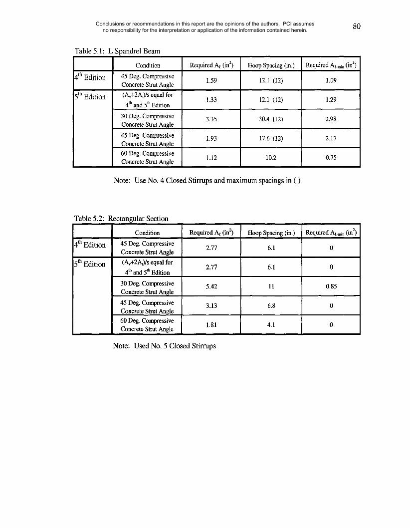
80
Table 5.1" L Spandrel Beam¯ 2Required At (in2) Required At-m~ (in)
4th Edition 1.59 1.09
5t~ Edition 1.33 1.29
Condition
45 Deg. CompressiveConcrete Strut Angle(Av+2At)/s equal for
4t~ and 5t~ Edition
30 Deg. CompressiveConcrete Strut Angle
45 Deg. CompressiveConcrete Strut Angle60 Deg. CompressiveConcrete Strut Angle
3.35 2.98
1.93 2.17
1.12
Hoop Spacing (in.)
12.1 (12)
12.1 (12)
30.4 (12)
17.6 (12)
10.2 0.75
Note: Use No. 4 Closed Stirrups and maximum spacings in ( )
Table 5.2: Rectangular Section
4t~ Edition
5th Edition
Condition45 Deg. CompressiveConcrete Strut Angle
(Av+2At)/s equal for4~ and 5~ Edition
30 Deg. CompressiveConcrete Strut An~le
45 Deg. CompressiveConcrete Strut An~le60 Deg. CompressiveConcrete Strut Angle
Required At (in2) Hoop Spacing (in.)
2.77 6.1
RequiredAt-rain (in2)
0
2.77 6.1 0
5.42 11 0.85
3.13 6.8 0
4.11.81
Note: Used No. 5 Closed Stirrups
Conclusions or recommendations in this report are the opinions of the authors. PCI assumes no responsibility for the interpretation or application of the information contained herein.

81
Table 5.3: Comparison of Tests to Prestressed Concrete Design Procedures
Loading
Combined Torsion,Shear, and Bending
No. ofTests
31
5t~ EditionEq. (4.3)
Mean
1.89
Ttest!Tcal
5th EditionEq. (4.4)
Mean
1.3
4t~ Edition
Mean
1.56
4t~ EditionFrom Report
Mean
1.773
Note: 4t~ Edition mean taken from the report is based on 63 tests
Conclusions or recommendations in this report are the opinions of the authors. PCI assumes no responsibility for the interpretation or application of the information contained herein.
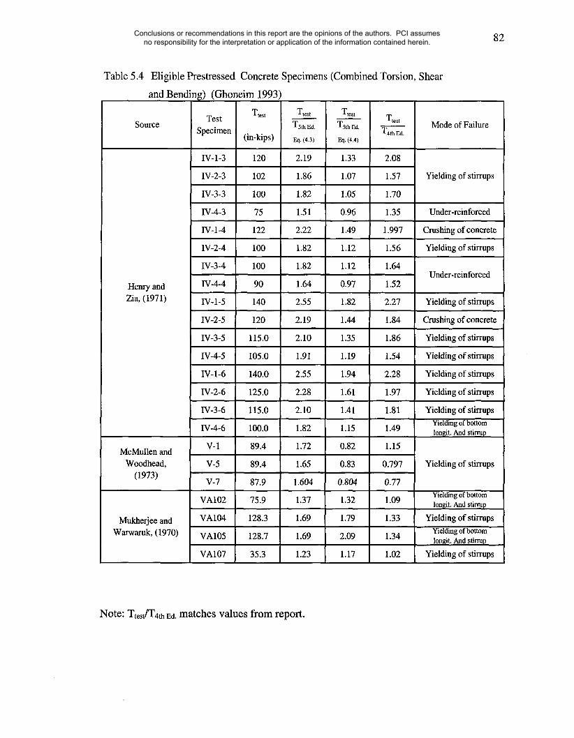
82
Table 5.4Eligible Prestressed
and Bending) (Ghoneim 1993)
Source TestSpecimen
Concrete Specimens (Combined Torsion, Shear
Ttest Ttest
T4~Ed.Mode of Failure
IV-1-3
IV-2-3
IV-3-3
IV-4-3
IV-l-4
IV-2-4
IV-3 -4
IV-4-4
IV-l-5
1V-2-5
IV-3-5
IV-l-6
IV-2-6
IV-3-6
IV-4-6
V-1
V-5
V-7
VA102
VA104
VA105
VA107
Yielding of stirrups
(in-kips)
120
102
100
75
122
100
100
90
140
120
115.0
105.0
140.0
125.0
115.0
100.0
89.4
89.4
87.9
75.9
128.3
128.7
Under-reinforced
Crushing of concrete
Yielding of stirrups
Under-reinforced
Ttest
TsthEd.Eq. (4.3)
2.19
1.86
1.82
1.51
2.22
1.82
1.82
1.64
2.55
2.19
2.10
1.91
2.55
2.28
2.10
1.82
1.72
1.65
1.604
1.37
1.69
1.69
1.23
Ttest
T5th gd.
Eq. (4,4)
1.33
1.07
1.05
0.96
1.49
1.12
1.12
0.97
1.82
1.44
1.35
1.19
1.94
1.61
1.41
1.15
0.82
0.83
0.804
1.32
1.79
2.09
1.17
Henry and
Zia, (1971) Yielding of stirrups
2.08
1.57
1.70
1.35
1.997
1.56
1.64
1.52
2.27
1.84
1.86
1.54
2.28
1.97
1.81
1.49
1.15
0.797
0.77
1.09
1.33
1.34
1.02
McMullen andWoodhead,
(1973)
35.3
Crushing of concrete
Yielding of stirrups
Yielding of stirrups
Yielding of stirrups
Yielding of stirrups
Yielding of stirrupsYielding of bottomlonllit. And stirrup
Mukherjee andWarwaruk, (1970)
Yielding of stirrups
Yielding of bottomlonsit. And stirrup
Yielding of stirrupsYielding of bottomlon~it. And stirrup
Yielding of stirrups
Note: Ttestfr4th Ed. matches values from report.
Conclusions or recommendations in this report are the opinions of the authors. PCI assumes no responsibility for the interpretation or application of the information contained herein.

83
Table 5.5
Source
McMullen andWoodhead,
(1973)
Ineligible Prestressed Concrete Specimens (Combined Torsion, Shear
and Bending) (Ghoneim 1993)
TestSpecimen
TtestTtest
W4th Ed.(in-kips)
69.9
28.3
90.0
105.0
35.3
81.9
105.0
135.0
78.9
81.9
78.9
75.9
Wrest
Eq. (4.3)
3.41
1.38
4.39
5.13
1.36
3.15
4.04
5.19
4.55
6.30
7.59
1.59
Ttest
Tsth Ed.
Eq. (4.4)
1.46
0.72
1.98
2.50
0.91
1.36
1.84
2.63
1.98
2.65
3.16
0.70
I1-2 2.11
11-3 0.75
II-4 3.02
11-5 3.55
III-2 0.89
UI-3 2.01
1II-5 2.48
III-6 3.79
V-2 2.54
V-3 3.63
V-4 3.84
V-6 0.83
Mode of Failure
Excess stirrupsspacing
Note: Ttest]T4th Ed. matches values from report.
Conclusions or recommendations in this report are the opinions of the authors. PCI assumes no responsibility for the interpretation or application of the information contained herein.

6 4 2 0
At
for
5th
Ed
itio
n w
as
calc
ulat
ed fr
om s
elec
ting
ast
rut a
ngle
of 3
0, 4
5 an
d 60
degr
ees.
PC
I Exa
mpl
e,T
u =
707
in.-
kips
Equ
atio
n (1
1-18
) of
AC
I 318
-02
Lim
its M
axim
um
Un
facto
red
~D
ead
Load
4th
--@
-- A
I (4t
h)
AIAI (5
th)(5t
h) 453
0 DegD
eg
| ~ A
I (5
th)
60
De
g
45 D
eg.
60 D
eg.
06
08
010
012
014
0
Unf
acto
red
Dea
d Lo
ad (
psf)
Fig
ure
5.1
" L
Se
ctio
n R
eq
uire
d A
t a
s a
fu
nct
ion
of S
tru
t A
ng
le
160
180
Conclusions or recommendations in this report are the opinions of the authors. PCI assumes no responsibility for the interpretation or application of the information contained herein.
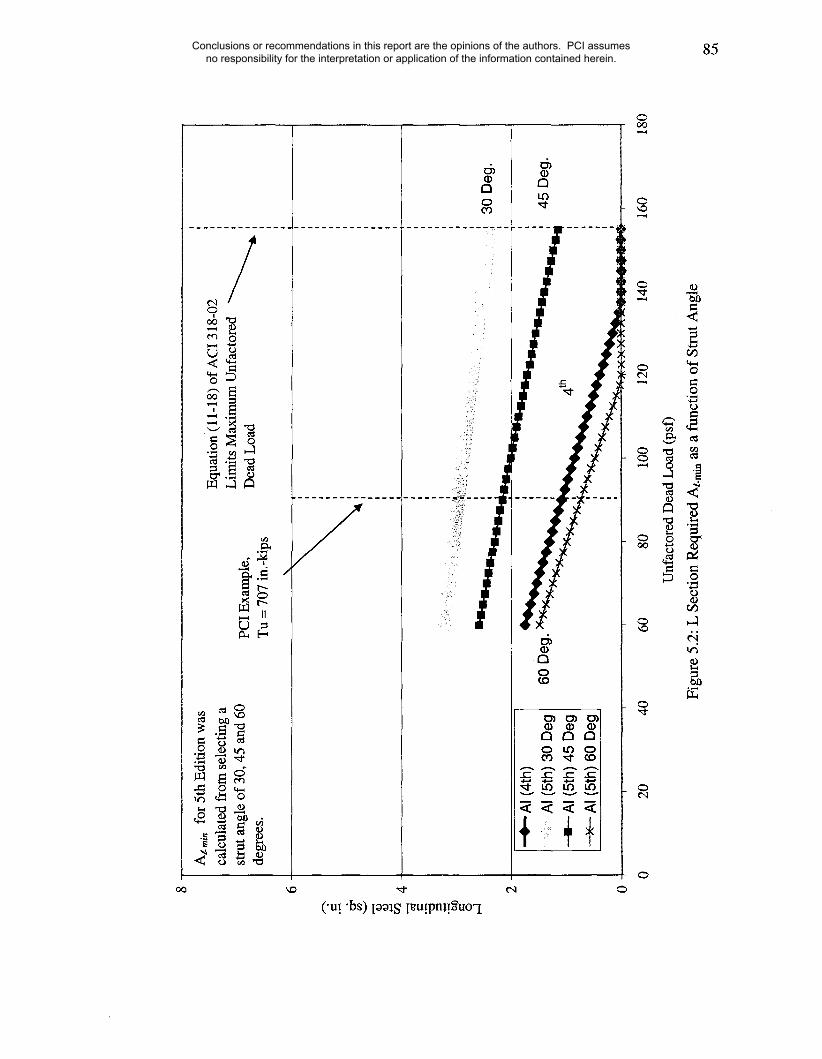
00
At.,
~i,
for
5th
Edi
tion
was
calc
ulat
ed fr
om s
elec
ting
ast
rut a
ngle
of 3
0, 4
5 an
d 60
degr
ees.
PC
I Exa
mpl
e,T
u =
707
in.-
kips
Equ
atio
n (1
1-18
) of
AC
I 318
-02
Lim
its M
axim
um
Un
facto
red
~D
ead
Load
-"~-
- A
I (4t
h)...
.. "A
I (5t
h) 3
0 D
eg~
AI
(5th
) 4
5 D
eg
,--x
--A
I (5
th) 6
0 D
eg
20
40
60
80
100
120
140
Unf
acto
red
Dea
d Lo
ad (
psf)
Fig
ure
5.2:
L S
ectio
n R
equi
red
At-
min
as
a fu
nctio
n of
Str
ut A
ngle
30 D
eg.
45 D
eg.
160
180
Conclusions or recommendations in this report are the opinions of the authors. PCI assumes no responsibility for the interpretation or application of the information contained herein.

JJ
II
Conclusions or recommendations in this report are the opinions of the authors. PCI assumes no responsibility for the interpretation or application of the information contained herein.

M T
(in-k
)
V (
k)
( in-
k )
2363
28.9
DE
AD
LO
AD
1 1
PD=
42 k
tW
d= 5
25 p
lf
I 1
ITd
= 10
08 in
-k
30’
2126
504
2363
1620 18
28.9
504
LIV
E L
OA
D
PL=
36k
TL=
864
in-k
30’
1620
432
1620
18
432
Fig
ure
5.4:
Exa
mpl
e 5.
1 fle
xura
l mom
ent,
shea
r, a
nd to
rque
dia
gram
s fo
r de
ad a
nd li
ve lo
ads
Conclusions or recommendations in this report are the opinions of the authors. PCI assumes no responsibility for the interpretation or application of the information contained herein.
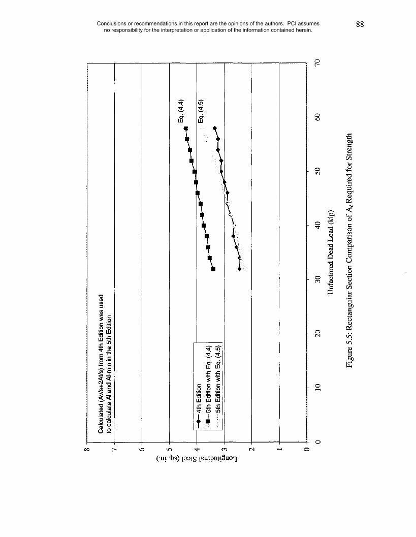
2 0
Cal
cula
ted
(Av/
s+2A
t/s) f
rom
4th
Edi
tion
was
use
dto
cal
cula
te A
I and
AI-m
in in
the
5th
Edi
tion
~--e
-- 4t
h Ed
ition
~ 5t
h Ed
ition
with
Eq.
(4.4
)~
5th
Editi
on w
ith E
q. (4
.5)
Eq.
(4.4
)
~ ~
Eq.
(4.
5)
10
20
30
40
50
60
Unf
acto
red
Dea
d Lo
ad (
kip)
Fig
ure
5.5:
Rec
tang
ular
Sec
tion
Com
paris
on o
f At R
equi
red
for
Str
engt
h
7O
Conclusions or recommendations in this report are the opinions of the authors. PCI assumes no responsibility for the interpretation or application of the information contained herein.
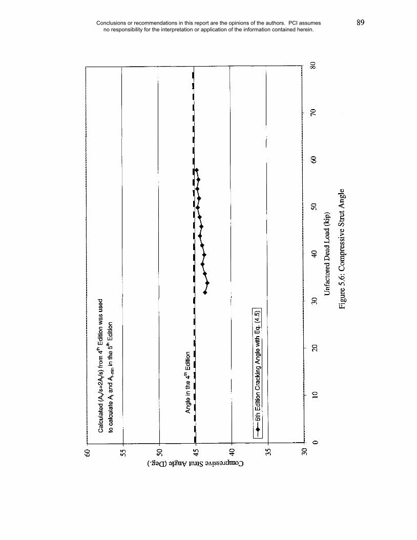
6O 55 35
3O
Cal
cula
ted
(A~/
s+2A
t/s) f
rom
4th
Edi
tion
was
use
dto
cal
cula
te A
~ an
d A
i.mi n
in th
e 5t
h Ed
ition
Ang
le in
the
4th
Ed
itio
n
--~-
-5th
Edi
tion
Cra
ckin
g A
ngle
with
Eq.
(4.
5)t
10
20
30
40
50
Unf
acto
red
Dea
d Lo
ad (
kip)
Figu
re 5
.6: C
ompr
essi
ve S
trut A
ngle
8O
Conclusions or recommendations in this report are the opinions of the authors. PCI assumes no responsibility for the interpretation or application of the information contained herein.

+ 4
th E
ditio
n...
......
.. 5t
h E
ditio
n (3
0 D
egre
es)
--I-
5th
Ed
itio
n (
45
De
gre
es)
--X
--5t
h E
ditio
n (6
0 D
egre
es)
Fig
ure
5.7:
20
30
40
50
60
Unf
acto
red
Dea
d Lo
ad (k
ip)
Sec
tion
Exa
mpl
e R
equi
red
At f
or S
tren
gth
as a
Fun
ctio
n of
the
Str
ut A
ngle
7O
Conclusions or recommendations in this report are the opinions of the authors. PCI assumes no responsibility for the interpretation or application of the information contained herein.
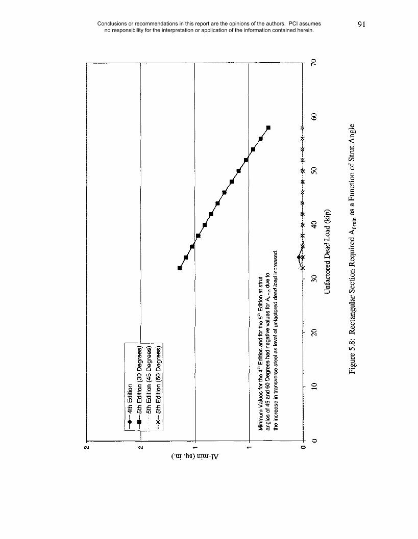
_~
~--
4th
Ed
itio
n
~ 5
th E
diti
on
(3
0 D
eg
ree
s)...
.... 5
th E
ditio
n (4
5 D
egre
es)
~ 5
th E
diti
on
(60
Deg
rees
)
Min
mum
Val
ues
for t
he 4
~ Ed
ition
and
for t
he 5
th E
ditio
n at
stru
tan
gles
of 4
5 an
d 60
Deg
rees
had
neg
ativ
e va
lues
for A
~.m
~n d
ue to
the
incr
ease
in tr
ansv
erse
ste
el a
s le
vel o
f unf
aoto
red
dead
load
incr
ease
d.
10
20
, ~ ~
x
, .
30
40
50
Unf
acto
red
Dea
d Lo
ad (
kip)
7O
Fig
ure
5.8
: R
ect
an
gu
lar
Se
ctio
n R
eq
uire
d A
t-ra
in a
s a
Fu
nct
ion
of
Str
ut
An
gle
Conclusions or recommendations in this report are the opinions of the authors. PCI assumes no responsibility for the interpretation or application of the information contained herein.

2.0
1.8
1.6
1.4
1.2
1.0
0.8
0.6
0.4
0.2
0.0
Are
a C
oncr
ete
= 50
4 in
.2
+ R
ecta
ngul
ar S
ectio
n (E
q. 4
.3)
,, R
ecta
ngul
ar S
ectio
n (E
q. 4
.4)
0.2
0.4
0.6
0.8
Rat
io (
x/(A
c^.5
)
1.2
Figu
re 5
.9: R
ecta
ngul
ar S
ectio
n R
atio
(A1
5th)
/(A1
4th)
Conclusions or recommendations in this report are the opinions of the authors. PCI assumes no responsibility for the interpretation or application of the information contained herein.

93
6. SUMMARY OF FINDINGS AND CONCLUSIONS
6.1 Findings
The 5t~ Edition example of the PCI Design Handbook required an additional amount of
longitudinal steel equal to about three times the amount required for the same example in
the 4th Edition for strength and almost double for minimum required longitudinal steel.
The design approach for torsion in the 4tla Edition of the PCI Design Handbook is based
on the skew-bending theory and on the thin-walled tube and space truss analogy
procedure in the 5t~ Edition of the same handbook. This observation triggered the
examination of both examples. A key design constraint was that in both approaches the
same total amount of transverse steel reinforcement is used for shear and torsion.
6.1.1 Adjustments
Some modifications to Design Example 4.4.2 of the PCI Design Handbook had to be
made in order to make proper comparisons of the two design procedures. As seen in
Chapter 4, the initial difference in required longitudinal steel for torsional strength
decreased to 1.3 times the amount in the 4th Edition after all necessary adjustments had
been made so that the two design examples were conducted under the same basic
conditions. A key adjustment was the use of the web-shear cracking concrete
contribution, Vow, in the 5th Edition instead of the minimum value, Vc--2~-~bwd, as it is
more appropriate for the spandrel beam from the PCI design example.
Conclusions or recommendations in this report are the opinions of the authors. PCI assumes no responsibility for the interpretation or application of the information contained herein.

94
6.1.2 Concrete Cover Spalling
The assumption of concrete cover spalling around the entire cross section was examined.
It was found that using the expression given in Equation (4.5) to calculate the concrete
area enclosed by the shear flow path, Ao, basically eliminated the remaining difference in
the required amount of longitudinal steel for strength. When Equation (4.5) was used
instead of Equation (4.4), the difference between A~ for both design procedures was
further reduced to 0.2 times the amount in the 4th Edition of the corrected value with Vow.
This finding was confirmed in Chapter 5. It would appear based on the results of the
parametric studies that the current assumption regarding spalling of the concrete cover is
too conservative with respect to the 4t~ Edition approach in the case of sections which are
tall and slender such as the spandrel beam studied in both editions of the PCI Design
Handbook.
6.2 Recommendations
The following recommendations are made regarding shear and torsion design of
precast/prestressed concrete spandrel beams.
1 .) Use Vow and Vci instead of the minimum value of 2xf~-~bwd for the nominal shear
strength provided by the concrete. Using the expression is appropriate since they
account for the effect of prestressing and are more relevant to the shear behavior
of prestressed members. Further, use of V~w and Vci will result in a decrease in
the required amount of torsional steel reinforcement for a given total amount of
transverse steel.
Conclusions or recommendations in this report are the opinions of the authors. PCI assumes no responsibility for the interpretation or application of the information contained herein.

95
Use Equation (6.1) in estimating the gross area enclosed by the shear flow path,
Ao, for spandrel beams:
2TL’PcP (6.1)A° = Acp q)~cncp
It is stated in Commentary Section R11.6.3.6 of the ACI Code 318-02 that, "The
expression for Ao given by Hsu1132 may be used if greater accuracy is desired"
when compared to the simplified equation of Ao = 0.85Aoh. The Hsu expression
referred to in Commentary Section R11.6.3.6 is Equation (6.1) shown above.
6.3 Future Work
1.) Additional work is needed in the form of tests of precast, prestressed concrete
spandrel beams to properly evaluate the end effects of warping torsion on restrained L
spandrel beams at end regions and more appropriately represent these effects in the
design of such members. It is possible that the current design approaches because of the
particular end restraint conditions and the geometry of the member do not properly
represent the ultimate mode of failure of precast prestressed spandrels such as those used
in parking garages and examined in this report.
2.) Examine if the 60 ksi limit, stated in Commentary Section Rll.6.3.10,
prestressing longitudinal steel used for torsion is applicable.
for
Conclusions or recommendations in this report are the opinions of the authors. PCI assumes no responsibility for the interpretation or application of the information contained herein.

96
ACI318,2002,
LIST OF REFERENCES
American Concrete Institute, Farmington Hills, MI
Henry, R.L. and Zia, P., "Prestressed Beams in Torsion, Bending, and Shear," Journal
of the Structural Division, Vol. 100, No. 5, May 1974, pp. 933-952
Hsu, T.T.C., "Torsion of Reinforced Concrete," Van Nostrand Reinhold Company,
Inc., 1984
Hsu, T.T.C., "ACI Shear and Torsion Provisions for Prestressed Hollow Girders,"
ACI Structural Journal, November-December 1997
Johnston, D.W. and Zia, P, "Prestressed Box Beams under Combined Loading,"
Journal of the Structural Division, Vol. 101, No.7, July 1975, pp. 1313-1331
Klein, G.J. "Design of Spandrel Beams," Final Report to the PCI, Research Project
No. 5, WJE Associates, Inc., 1986
MacGregor, J.G. and Ghoneim, M.G., "Design For Torsion," ACI Structural Journal,
March-April 1995, pp. 211-217
Conclusions or recommendations in this report are the opinions of the authors. PCI assumes no responsibility for the interpretation or application of the information contained herein.

97
MacGregor, J.G. and Ghoneim, M.G., "Evaluation of Design Procedures for Torsion
in Reinforced and Prestressed Concrete," Structural Engineering Report, No. 184,
University of Alberta, February 1993, pp. 52-54
McMullen, A.E. and Woodhead, H.R., "Experimental Study of Prestressed Concrete
Under Combined Torsion, Bending, And Shear," PCI Journal, September-October
1973, pp. 85-100
Mukherjee, P.R. and Warwaruk, J., "Torsion, Bending, and Shear in Prestressed
Concrete," Journal of the Structural Division, Vol. 97, No. 4, April 1971, pp. 1063-
1079
PCI, 4th Edition, "PCI Design Handbook," Raths, Raths & Johnson, Inc., 1992 pp. 4-
34 to 4-36
PCI, 5th Edition, "PCI Design Handbook," Raths, Raths & Johnson, Inc., 1999, pp. 4-
43 to 4-45
Zia, P. and McGee, W.D., "Torsion Design of Prestressed Concrete," PCI Journal,
March-April 1974, pp. 47-58
Conclusions or recommendations in this report are the opinions of the authors. PCI assumes no responsibility for the interpretation or application of the information contained herein.