BUS Cables Nexans Deutschland Industries Sieboldstraße 10 ... - przewody BUS.pdf · BUS Cables....
24
BUS Cables
Transcript of BUS Cables Nexans Deutschland Industries Sieboldstraße 10 ... - przewody BUS.pdf · BUS Cables....

BUS Cables
stoehr
Nexans Deutschland Industries Sieboldstraße 10 90411 Nürnberg Germany Tel: 0049 (0) 911 5207 0 Fax: 0049 (0) 911 5207 558 E-mail: [email protected] Internet: www.nexans.de
stoehr

Table of contentsPage
Why BUS Systems?
Field BUS
DESINA
AS-Interface Bus 1
Interbus 3
Profibus 5
POF Bus 9
Hybrid Bus 11
Industrial Ethernet Bus 13
CAN Bus 15
Sensor Bus 17
General information
Bus Types and Sensor Bus

Why Bus Systems? Since the beginning of the 80sBus Systems are well knownthrough the EDP (electronic dataprocessing). Because of the highhardware costs the first typicalstructures were mainframes whichcontrolled the whole data hand-ling and organized several termi-nals. For this structure (so called”Star Topologies”) there is a needfor a connection between everywork station and the mainframewhich means a tremendous effortof cabling.
Due to the decreasing hardwarecosts the terminals were replacedthrough PCs and workstationswhich were able to organize themain part of data processing bythemselves. Now the mainframescould be replaced through lessefficiently but cheaper minicomputers or workstations.The communication between thesingle computers was reconvertedto Bus systems (Ethernet, Thin-ethernet, Arcnet) or ”ring topolo-gies” (Token Ring etc.), whichallows a simple and flexiblecabling above always one cable.
The same effect was observedin/realized for the machineryand installation engineering.
The central configuration of theelectrical shift units, control technicand in-/output-devices in switch-boards means a high effort ofcabling and restricted flexibilityin kind of any enhancements ornecessary accommodations.Above all the high number ofcontacts and conductors meansa waste of time in trouble shootingby implementing and service.An advantage could be thedecentralisation of the electriccomponents, e.g. the transfer ofthe control- and shift-units directlyto the periphery of the machineor construction. Instead of an thickstranded cable there is just a thincable remaining.
Furthermore the networking ofsystems gains an increase ofinterest, especially the decentraldistributed intelligence in theIndustry- Building- Environment-or Traffic-Automation. Here BusSystems are used as an commu-nication medium for sectoredactuators, sensors and steeringin the automation technic andall over there where electronicmodules has to be connectedwithout a big effort of cabling.Only one cable connects allcomponents.

The summarized advantages of Bus Systems are as follows:
• Less wiring/cabling• Small floor space in switchboards• More transparency• Faster diagnose• Better availability• Higher safety
All these pros leads to relevant cost advantages
The different requirements to the bussystem, the variety of technicalsolutions but also corporate policy leads to a variety of bussystemswithout a single standard.
Field bus is the generic name for all bussystems which are used for themetrology, steering and controlling engineering. These are:
• CAN• Profibus• Interbus• ASI Bus
According to the DIN (German institute for standardisation) standard afield bus in general should transmit a small volume of data in fast timeseries on a digital compare between sensors/actuators and steering. Asthe requirements to the bus system depends on the level of automation,there is no field bus which can solve all tasks optimal together.
Following table should show a short overview of the most importantfeatures of the three first called bus systems:
Field Bus
Highest BPSe Biggest Maximal number StandardisationDimension of participants
CAN Bus 1 Mbit/s to 40 m 1 km at 50 Kbit/s 64 (128) ISO 11898Profibus 500 Kbit/s to 200 m 1200 m at 93 Kbit/s 256 ISO 19245Interbus 500 Kbit/s to 40 m 12,8 km at 400 m Segments 256 ISO 19258

Factorylevel
Bus cycle time< 1000 msec
Celllevel
Bus cycle time< 100 msec
Fieldlevel
Bus cycle time< 10 msec
Drive I/O Valves Fielddevice
Trans-mitter
Fielddevice
CNC
DCSPLC
VME/PC
Host
PC/VME
PROFIBUS-FMS
PROFIBUS-DP PROFIBUS-PA
Example Profibus
MMS, TCP/IP Backbone
Areacontroller
Application level of the Profibus
Profi-BUS Family
Automation forGeneral Purposes
PROFIBUS-FMSUniversal
• Large variety of applications• Mulit-master communication
FactoryAutomation
PROFIBUS-DPFast
• Plug and Play• Efficient and cost effective
ProcessAutomation
PROFIBUS-PAApplication oriented
• Powering over the bus• Intrinsic Safety
EN 50170 Volume 2 and DIN 19245 Part 1 to 4
Dev
ice
prof
iles
App
licat
ion
Prof
iles

DESINA DESINA - DEcentral and Standardised INstAllation technic
DESINA describes an all included concept about the standardization ofmachines in cooperation with leading companies in machine tool andautomotive segments. For cables it is mainly the colour as follows:
orange - Servocablegreen - Measurement equipmentviolet - Bus or Hybridcableyellow - Sensor/Actorcableblack - powercablegrey - 24 Volt supply
The jacket must be resistant to industrial lubricants. The standardizationallows in total a reduction of costs and a quick localisation of the failurein case of a damage – in the past there was a bulk of black or greycables making it difficult for maintenance and service people to locatethe right one. Colour coding of DESINA cables is reducing that problemsignificantly, especially as components have self diagnosis functionality.
More details are available under http://www.desina.de
Halogen free
BrClFl
Admissible ambienttemperature forcontinuous duty
operation
Fire retardant Low corrosivity
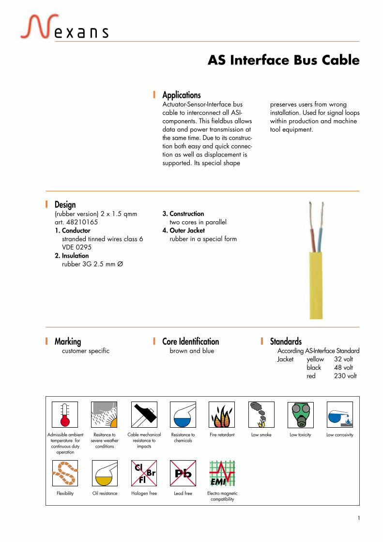
ApplicationsActuator-Sensor-Interface buscable to interconnect all ASI-components. This fieldbus allowsdata and power transmission atthe same time. Due to its construc-tion both easy and quick connec-tion as well as displacement issupported. Its special shape
Design(rubber version) 2 x 1.5 qmmart. 482101651. Conductor
stranded tinned wires class 6VDE 0295
2. Insulationrubber 3G 2.5 mm Ø
3. Constructiontwo cores in parallel
4. Outer Jacketrubber in a special form
Markingcustomer specific
Core Identificationbrown and blue
AS Interface Bus Cableevtl. Text
Oil resistance
Cable mechanicalresistance to
impacts
Electro magneticcompatibility
1
Resitance tosevere weather
conditions
Resistance tochemicals
Low smoke Low toxicity
Flexibility Lead free
StandardsAccording AS-Interface StandardJacket yellow 32 volt
black 48 voltred 230 volt
preserves users from wronginstallation. Used for signal loopswithin production and machinetool equipment.

AS Interface Bus Cable
Type Art-no. Conductor Jacket Application Copper weight Bendingcontent radius
Aug
ust 2
002
· Cop
yrig
ht 2
002
· Nex
ans
2
2x1,5 48210165 76x0,15 rubber self healing 29,0 85 kg VDE 04723G3G tinned effect, very soft part 603
test H
2x1,5 48215015 76x0,15 PUR chemical 29,0 85 kg VDE 04723G11Y tinned resistance 29,0 85 kg part 603
test H
Type Art-no. Impedance Attenuation Capacity Screening ConductorEffectiveness resistance
2 x 1,5 48210165 n. a. n. a. nom. 55 pF/m n. a. DIN VDE 02953G3G
2 x 1,5 48215015 n. a. n. a. nom. 55 pF/m n. a. DIN VDE 02953G11Y
Type Art-no.
2x1,5 48210165 -25°C to in • • • • • • •3G3G +85°C black
2x1,5 48215015 -25°C to in • • • • • • •3G11Y +85°C black
BrClFl

Halogen free
BrClFl
Admissible ambienttemperature forcontinuous duty
operation
Fire retardant Low corrosivity
ApplicationsInterbus cables connect sensorsand actors with all standardequipment in automation. Ourproduct range fulfill the specialrequirement of• Standard for fix installation
or few bending
Design(standard) 3 x 2 x AWG 24/7PVC art. 444 7651. Conductor
bare stranded copperAWG 24/7 (0.6 mmØ)
2. Insulationsolid polyethylene 1.2 mm Ø
3. Twistingtwo cores to pair,3 pairs together
4. Screenbare copper braid with plastictape below
5. Outer sheathPVC, violet
MarkingBus: 3x2xAWG24/72YCY (100 ohm)
Core Identificationwhite/browngrey/pinkyellow/green
Interbus
Oil resistance
Cable mechanicalresistance to
impacts
Electro magneticcompatibility
3
Resitance tosevere weather
conditions
Resistance tochemicals
Low smoke Low toxicity
Flexibility Lead free
StandardsAccording Interbus requirements
• For use in chain• HFFR (Halogen free & flame
retardant)• Direct burial• Food industry• Marine and Submarine• Railway Systems
INTERBUS

3x2xAWG24/19 444764 0,064 MHz/120 Ω ± 20 % 0,256 MHz/ 1,5 dB 50 pF/m ≤ 96 Ω/kmLi 2YC11Y 1 MHz / 100 Ω ± 15 % 0,772 MHz/ 2,4 dB
1 MHz/ 2,7 dB4 MHz/ 2,7 dB
10 MHz/ 8,4 dB16 MHz/ 11,2 dB20 MHz/ 11,9 dB
3x2xAWG24/7 444765 0,064 MHz/120 Ω ± 20 % 0,256 MHz/ 1,5 dB 50 pF/m ≤ 96 Ω/kmLi 2YCY 1 MHz / 100 Ω ± 15 % 0,772 MHz/ 2,4 dB
1 MHz/ 2,7 dB4 MHz/ 2,7 dB
10 MHz/ 8,4 dB17 MHz/ 11,2 dB20 MHz/ 11,9 dB
3x2xAWG24/7 444771 0,064 MHz/120 Ω ± 20 % 0,256 MHz/ 1,5 dB 50 pF/m ≤ 96 Ω/km+ 3x1,0 1 MHz / 100 Ω ± 15 % 0,772 MHz/ 2,4 dBLI2YCY 1 MHz/ 2,7 dB
4 MHz/ 2,7 dB10 MHz/ 8,4 dB18 MHz/ 11,2 dB20 MHz/ 11,9 dB
3x2xAWG24/19 444746 - 20°C to in • • • • • • •Li 2YC11Y +70°C black
3x2xAWG24/7 444745 - 20°C in • • • • •Li 2YCY +70°C black
3x2xAWG24/7 444771 - 20°C in • • • • •+ 3x1.0 2YCY +70°C black
Interbus
Type Art-no. Conductor Jacket Application Copper weight Bending radiuscontent
Aug
ust 2
002
· Cop
yrig
ht 2
002
· Nex
ans
4
3x2xAWG24/19 444764 Bare copper stranded PUR violet Chain cable 34,7 kg 73 kg Single bending ≥ 40 mmLi 2YC11Y AWG 24/19 7,6 mm multiple bend. ≥ 160 mm
3x2xAWG24/7 444765 Bare copper stranded PVC violet Standard cable 32,4 kg 64 kg Single bending ≥ 40 mmLi 2YCY AWG 24/7 7,1 mm for fix installation multiple bend. ≥ 160 mm
or some movement
3x2xAWG24/7 444771 Bare copper stranded PVC violet Installation bus 56,7 kg 108 kg Single bending ≥ 64 mm+ 3x1,0 AWG 24/7 (bus) 8,0 mm plus power supply multiple bend. ≥ 160 mm2YCY 1.0 stranded bare
copper
Type Art-no. Impedance Attenuation Capacity Conductor(nom.) resistance
Type Art-no.BrCl
Fl
Halogen free
BrClFl
Admissible ambienttemperature forcontinuous duty
operation
Fire retardant Low corrosivity
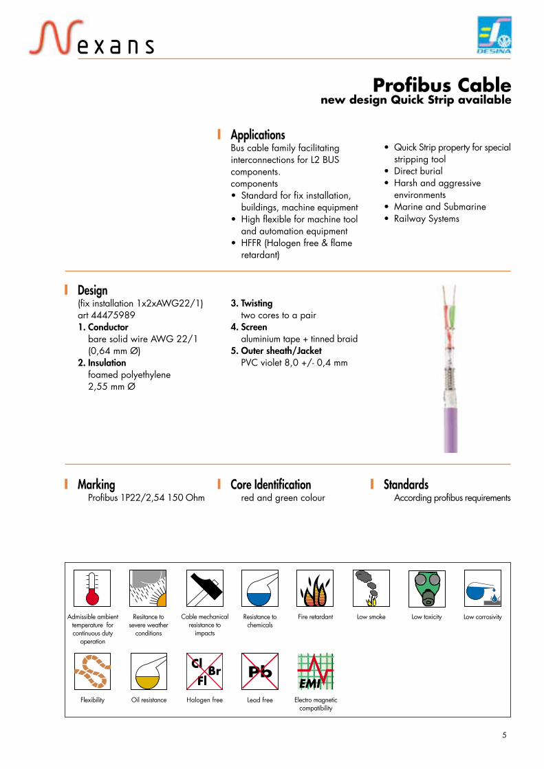
ApplicationsBus cable family facilitatinginterconnections for L2 BUScomponents.components• Standard for fix installation,
buildings, machine equipment• High flexible for machine tool
and automation equipment• HFFR (Halogen free & flame
retardant)
Design(fix installation 1x2xAWG22/1)art 444759891. Conductor
bare solid wire AWG 22/1(0,64 mm Ø)
2. Insulationfoamed polyethylene2,55 mm Ø
3. Twistingtwo cores to a pair
4. Screenaluminium tape + tinned braid
5. Outer sheath/JacketPVC violet 8,0 +/- 0,4 mm
MarkingProfibus 1P22/2,54 150 Ohm
Core Identificationred and green colour
Profibus Cablenew design Quick Strip available
Oil resistance
Cable mechanicalresistance to
impacts
Electro magneticcompatibility
5
Resitance tosevere weather
conditions
Resistance tochemicals
Low smoke Low toxicity
Flexibility Lead free
StandardsAccording profibus requirements
• Quick Strip property for specialstripping tool
• Direct burial• Harsh and aggressive
environments• Marine and Submarine• Railway Systems
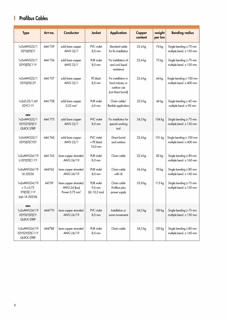
Profibus Cables
Type Art-no. Conductor Jacket Application Copper weight Bending radiuscontent per km
6
1x2xAWG22/1 444 759 solid bare copper PVC violet Standard cable 22,4 kg 74 kg Single bending ≥ 75 mm02YS(ST)CY AWG 22/1 8,0 mm for fix installation multiple bend. ≥ 150 mm
1x2xAWG22/1 444 756 solid bare copper PUR violet Fix installation oil 22,4 kg 72 kg Single bending ≥ 75 mm02YS(ST)C11Y AWG 22/1 8,0 mm and cool liquid multiple bend. ≥ 150 mm
resistance
1x2xAWG22/1 444 757 solid bare copper PE black Fix installation in 22,4 kg 64 kg Single bending ≥ 100 mm02YS(ST)C2Y AWG 22/1 8,0 mm food industry or multiple bend. ≥ 400 mm
outdoor use(not direct burial)
1x2x0,25/1,60 444 758 solid bare copper PUR violet Chain cable/ 22,0 kg 44 kg Single bending ≥ 45 mm02YC11Y 0,25 mm2 6,0 mm flexible application multiple bend. ≥ 90 mm
new1x2xAWG22/1 444 775 solid bare copper PVC violet Fix installation for 34,5 kg 104 kg Single bending ≥ 75 mm02YS2Y(ST)CY AWG 22/1 8,0 mm special working multiple bend. ≥ 150 mmQUICK STRIP tool
1x2xAWG22/1 444 760 solid bare copper PVC violet Direct burial 22,4 kg 101 kg Single bending ≥ 100 mm02YS(ST)CY2Y AWG 22/1 + PE black and outdoor multiple bend. ≥ 400 mm
10,0 mm
1x2xAWG24/19 444 763 bare copper stranded PUR violet Chain cable 22,4 kg 82 kg Single bending ≥ 80 mmLi 02Y(ST)C11Y AWG 24/19 8,0 mm multiple bend. ≥ 160 mm
1x2xAWG24/19 444762 bare copper stranded PUR violet Chain cable 34,4 kg 95 kg Single bending ≥ 80 mmUL 20236 AWG 24/19 8,0 mm with UL multiple bend. ≥ 160 mm
1x2xAWG24/19 44739 bare copper stranded PUR violet Chain cable 53,8 kg 115 kg Single bending ≥ 75 mm+ 3 x 0,75 AWG 24 (bus) 9,6 mm Profibus plus multiple bend. ≥ 150 mm
9YI(ST)C11Y Power 0,75 mm2 (UL 10,3 mm) power supply(opt. UL 20236)
new1x2xAWG24/19 444770 bare copper stranded PVC violet Installation or 34,5 kg 100 kg Single bending ≥ 75 mm
02YS2Y(ST)CY AWG 24/19 8,0 mm some movements multiple bend. ≥ 150 mmQUICK STRIP
1x2xAWG24/19 444788 bare copper stranded PUR violet Chain cable 34,5 kg 100 kg Single bending ≥ 80 mm02YS2Y(ST)C11Y AWG 24/19 8,0 mm multiple bend. ≥ 160 mm
QUICK STRIP
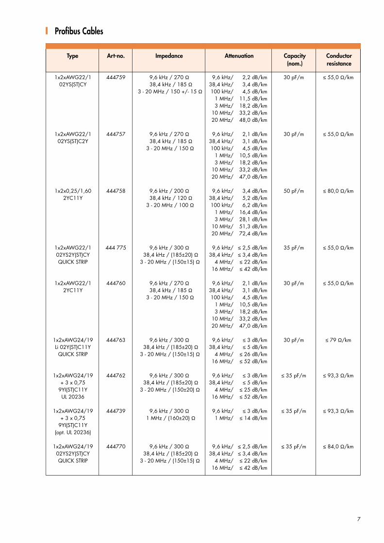
1x2xAWG22/1 444759 9,6 kHz / 270 Ω 9,6 kHz/ 2,2 dB/km 30 pF/m ≤ 55,0 Ω/km02YS(ST)CY 38,4 kHz / 185 Ω 38,4 kHz/ 3,4 dB/km
3 - 20 MHz / 150 +/- 15 Ω 100 kHz/ 4,5 dB/km1 MHz/ 11,5 dB/km3 MHz/ 18,2 dB/km
10 MHz/ 33,2 dB/km20 MHz/ 48,0 dB/km
1x2xAWG22/1 444757 9,6 kHz / 270 Ω 9,6 kHz/ 2,1 dB/km 30 pF/m ≤ 55,0 Ω/km02YS(ST)C2Y 38,4 kHz / 185 Ω 38,4 kHz/ 3,1 dB/km
3 - 20 MHz / 150 Ω 100 kHz/ 4,5 dB/km1 MHz/ 10,5 dB/km3 MHz/ 18,2 dB/km
10 MHz/ 33,2 dB/km20 MHz/ 47,0 dB/km
1x2x0,25/1,60 444758 9,6 kHz / 200 Ω 9,6 kHz/ 3,4 dB/km 50 pF/m ≤ 80,0 Ω/km2YC11Y 38,4 kHz / 120 Ω 38,4 kHz/ 5,2 dB/km
3 - 20 MHz / 100 Ω 100 kHz/ 6,2 dB/km1 MHz/ 16,4 dB/km3 MHz/ 28,1 dB/km
10 MHz/ 51,3 dB/km20 MHz/ 72,4 dB/km
1x2xAWG22/1 444 775 9,6 kHz / 300 Ω 9,6 kHz/ ≤ 2,5 dB/km 35 pF/m ≤ 55,0 Ω/km02YS2Y(ST)CY 38,4 kHz / (185±20) Ω 38,4 kHz/ ≤ 3,4 dB/kmQUICK STRIP 3 - 20 MHz / (150±15) Ω 4 MHz/ ≤ 22 dB/km
16 MHz/ ≤ 42 dB/km
1x2xAWG22/1 444760 9,6 kHz / 270 Ω 9,6 kHz/ 2,1 dB/km 30 pF/m ≤ 55,0 Ω/km2YC11Y 38,4 kHz / 185 Ω 38,4 kHz/ 3,1 dB/km
3 - 20 MHz / 150 Ω 100 kHz/ 4,5 dB/km1 MHz/ 10,5 dB/km3 MHz/ 18,2 dB/km
10 MHz/ 33,2 dB/km20 MHz/ 47,0 dB/km
1x2xAWG24/19 444763 9,6 kHz / 300 Ω 9,6 kHz/ ≤ 3 dB/km 30 pF/m ≤ 79 Ω/kmLi 02Y(ST)C11Y 38,4 kHz / (185±20) Ω 38,4 kHz/ ≤ 5 dB/kmQUICK STRIP 3 - 20 MHz / (150±15) Ω 4 MHz/ ≤ 26 dB/km
16 MHz/ ≤ 52 dB/km
1x2xAWG24/19 444762 9,6 kHz / 300 Ω 9,6 kHz/ ≤ 3 dB/km ≤ 35 pF/m ≤ 93,3 Ω/km+ 3 x 0,75 38,4 kHz / (185±20) Ω 38,4 kHz/ ≤ 5 dB/km
9YI(ST)C11Y 3 - 20 MHz / (150±20) Ω 4 MHz/ ≤ 25 dB/kmUL 20236 16 MHz/ ≤ 52 dB/km
1x2xAWG24/19 444739 9,6 kHz / 300 Ω 9,6 kHz/ ≤ 3 dB/km ≤ 35 pF/m ≤ 93,3 Ω/km+ 3 x 0,75 1 MHz / (160±20) Ω 1 MHz/ ≤ 14 dB/km
9YI(ST)C11Y(opt. UL 20236)
1x2xAWG24/19 444770 9,6 kHz / 300 Ω 9,6 kHz/ ≤ 2,5 dB/km ≤ 35 pF/m ≤ 84,0 Ω/km02YS2Y(ST)CY 38,4 kHz / (185±20) Ω 38,4 kHz/ ≤ 3,4 dB/kmQUICK STRIP 3 - 20 MHz / (150±15) Ω 4 MHz/ ≤ 22 dB/km
16 MHz/ ≤ 42 dB/km
Profibus Cables
7
Type Art-no. Impedance Attenuation Capacity Conductor(nom.) resistance

1x2xAWG22/1 444759 in • • • • •02YS(ST)CY black
1x2xAWG22/1 444756 in • • • • • • •02YS(ST)C11Y black
1x2xAWG22/1 444757 in • • • • • • • •02YS(ST)C2Y black
1x2x0,25/1,60 444758 in • • • • • • •2YC11Y black
1x2xAWG22/1 444775 in • • • • •02YS2Y(ST)CY blackQUICK STRIP
1x2xAWG22/1 444760 in • • • • •02YS(ST)CY2Y black
1x2xAWG24/19 444763 in • • • • • • •Li 02Y(ST)C11Y black
RSL 444762 in • • • • • • • •1x2xAWG24/19 black
UL 20236
RSL 444739 in • • • • • • • •1x2xAWG24/19 black
+ 3 x 0,759YI(ST)C11Y
(opt. UL 20236)
1x2xAWG24/19 444770 in • • • • •02YS2Y(ST)CY blackQUICK STRIP
1x2xAWG24/19 444788 in • • • • • • • •02YS2Y(ST)C11Y black
QUICK STRIP
Profibus Cable
Aug
ust 2
002
· Cop
yrig
ht 2
002
· Nex
ans
8
Type Art-no.BrCl
Fl

Halogen free
BrClFl
Admissible ambienttemperature forcontinuous duty
operation
Fire retardant Low corrosivity
ApplicationsUsed within machine tool andproduction equipment. Suitablefor harsh environments. Strainrelease through Aramidyarn.Resistance again oil and coatingliquids.
Design(1xPOF PUR) 444728801. Conductor
980/10002. Insulation
PE black
3. Filler (optional)Aramidyam
4. Outer sheathPVC 5,7 mm, violett
Markingcustomer specific
Core Identificationcoded with numbers on2- and 4-core versions
POF Bus Cable
Oil resistance
Cable mechanicalresistance to
impacts
Electro magneticcompatibility
9
Resitance tosevere weather
conditions
Resistance tochemicals
Low smoke Low toxicity
Flexibility Lead free
StandardsDesina conform
Type Approval CertificatesDesina conform

POF 1 980/1000 44472880 - 20°C to in • • • • • • •1 x POF +70°C black
POF 2 980/1000 44471689 - 20°C in • • • • • • •2 x POF +70°C black
POF 4 980/1000 44471789 - 20°C in • • • • • • •4 x POF +70°C black
POF Bus Cable
Type Art-no. Conductor Jacket Application Copper weight Bending radiuscontent
Aug
ust 2
002
· Cop
yrig
ht 2
002
· Nex
ans
10
POF 1 980/1000 44472880 980/1000 PUR violet Plastical Optical No copper 30 kg1 x POF 5,7 mm Fiber signal
cable
POF 2 980/1000 44471689 980/1000 PUR violet Plastical Optical No copper 60 kg2 x POF 6,0 mm Fiber signal
cable
POF 4 980/1000 44471789 980/1000 PUR violet Plastic Optial No copper 95 kg4 x POF 7,1 mm Fiber signal
cable
Type Art-no.BrCl
Fl

Halogen free
BrClFl
Admissible ambienttemperature forcontinuous duty
operation
Fire retardant Low corrosivity
ApplicationsUsed within machine tool orproduction equipment. Polymeroptic fibers provide maximumEMI resistance. Copper corestransport power to controlledhydraulic and other actuators andsensors. Suitable for harshenvironments due to materialsand desugn used.
Design(POF + 4 x 1,5 mm2 PUR)444794891. Conductor
Polymer Optical Fiber (bus)+ bare copper strandedconductor with 1,5 mm2
(power)2. Insulation
Polyolefin (POF) 2,2 mmPUR (power) 2,3 mm
3. Twistingtwo POF´s twisted with fillersand with four power cores andwrapped with a tape
4. Outer JacketPUR violet 9,0 mm
Markingcable type, dimension, DESINA
Core Identificationpower cores black withnumbersbus cores red and greenPOF cores with numbers
Hybrid Bus Cable
Oil resistance
Cable mechanicalresistance to
impacts
Electro magneticcompatibility
11
Resitance tosevere weather
conditions
Resistance tochemicals
Low smoke Low toxicity
Flexibility Lead free
Standardsacc. DESINA and Profibusrequirements

Twin-Tech- 44474289 300 @ 9,6 kHz ≤ 3 dB/9,6 MHz 1 kHz: ≤ 60 pF/m 1,5 kV acc. at 20 °C:Busleitung (185 ± 20) @ 38,4 kHz ≤ 5 dB/38,4 MHz DIN VDE 0472 core 1,5 mm2:
1P24 + 4x1,5 (150 ± 15) @ 3 - 20 MHz ≤ 26 dB/4 MHz part 509 test B ≤ 13,7 Ω/kmDESINA ≤ 55 dB/16 MHz BUS-cores:
≤ 89,9 Ω/km
Twin-Tech- 44479489 n. S. POF n. S. POF n. S. 2 kV acc. at 20 °C:Hybrid DIN VDE 0472 ≤ 13,3 Ω/km
HSL18Y + 4x1,5 part 509 test B power+ 2 POF
Twin-Tech- 44474289 bare conductor PUR violet combined 22,7 kg 119 kg 12xDBuscable stranded 11,0 mm Energy/Bus
1x2xAWG24 + 1,5 mm2 chain cable4x1,5 DESINA
Twin-Tech- 44479489 bare conductor PUR violet as combined 55,8 kg 358 kg 15xDHybridcable stranded 9,0 mm Energy/Control
HSL18Y 4x1,5 + 1,5 mm2 cable in for2 POF DESINA chain
Hybrid Bus Cable
Type Art-no. Conductor Jacket Application Copper weight Bendingcontent per km radius
Aug
ust 2
002
· Cop
yrig
ht 2
002
· Nex
ans
12
Type Art-no. Impedance Attenuation Capacity Test voltage Conductor(bus) per km resistance
1P24 + 4x1,5 44474289 - 40°C to in • • • • • • •+80°C black
HSL18Y 4x1,5 +2 44479489 - 20°C in • • • • • • •+70°C black
Type Art-no.BrCl
Fl

Halogen free
BrClFl
Admissible ambienttemperature forcontinuous duty
operation
Fire retardant Low corrosivity
ApplicationsCommunication betweenautomation equipment andcomputer systems within factoriesand production machinery.Suitable for industrial twisted pairnetworks facilitating ISDNconnection and WAN (WideArea Network)
Design(fix installation-standard)444705891. Conductor
bare solid wire AWG 22/1(0,64 mmØ)
2. Insulationsolid polyethylene 1,5 mm
3. Twistingtwo cores to a pair and twopairs together
4. Inner Jacketspecial material with plastictape below
5. Screenaluminium tape + tinned braid
6. Outer JacketPVC violet
MarkingIE-BUS 2x2xAWG22/1
Core Identificationorange + bluewhite + yellow
Industrial Ethernet Bus Cable
Oil resistance
Cable mechanicalresistance to
impacts
Electro magneticcompatibility
13
Resitance tosevere weather
conditions
Resistance tochemicals
Low smoke Low toxicity
Flexibility Lead free
StandardsAccording

2x2xAWG22/1 44470589 100 Ω ± 15 % 5,9 dB/10 MHz 500 MΩ · km max. 10 mΩ/km 62 Ω/km2YH(ST)CY 23,5 dB/100 MHz
2x2xAWG22/19 44470689 100 Ω ± 15 % 5,9 dB/10 MHz 500 MΩ · km max. 10 mΩ/km 60 Ω/km2YH(ST)C11Y 23,5 dB/100 MHz
2x2xAWG22/7 44470789 100 Ω ± 15 % 7,8 dB/10 MHz 500 MΩ · km max. 10 mΩ/km 60 Ω/km2YH(ST)CH 26,4 dB/100 MHz
2x2xAWG22/1 44470589 AWG 22/1 PVC violet installation 29,6 65 kg 10 x d single2YH(ST)CY (0,32 qmm) 6,5 mm cable 15 x d multiple
2x2xAWG22/19 44470689 AWG 22/19 PUR violet trailing 34,5 75 kg 10 x d single2YH(ST)C11Y (0,38 qmm) 6,9 mm cable 30 x d multiple
2x2xAWG22/7 44470789 AWG 22/7 HFFR violet marine 31,0 66 kg 10 x d single2YH(ST)CH (0,35 qmm) 6,5 mm cable 15 x d multiple
Industrial Ethernet Bus Cable
Type Art-no. Conductor Jacket Application Diameter weight Bendingradius
Aug
ust 2
002
· Cop
yrig
ht 2
002
· Nex
ans
14
Type Art-no. Impedance Attenuation Insulation Couple Conductor@ 1 - 100 MHz nominal 100 m resistance resistance resistance
2x2xAWG22/1 44470589 - 40°C to in • • • • •2YH(ST)CY +70°C black
2x2xAWG22/19 44470689 - 40°C to in • • • • • •2YH(ST)C11Y +70°C black
2x2xAWG22/7 44470789 - 20°C to in • • • • • • • •2YH(ST)C11Y +70°C black
Type Art-no.BrCl
Fl

Halogen free
BrClFl
Admissible ambienttemperature forcontinuous duty
operation
Fire retardant Low corrosivity
ApplicationsBus cable to connect ControllerAera Network components.Transmission characteristics:1 Mbit/s up to 40 m50 Kbit/s up to 1 kmFlexible cable to be used formachinery equipment andindustrial environments. Suitablefor harsh environments.
Design(CAN BUS flex) 1x2x0,25 PURart. 4447541. Conductor
bare stranded copper0,25 qmm (0,7 mm Ø)
2. Insulationsolid polyethylene 1,8 mm Ø
3. Twistingtwo cores to a pair
4. Screentinned braid
5. Outer sheath/JacketPVC violet 6,0 mm
MarkingBus: 1x2x0,25 PUR
Core Identificationwhite/browngreen/yellow
Can-Bus Cable
Oil resistance
Cable mechanicalresistance to
impacts
Electro magneticcompatibility
15
Resitance tosevere weather
conditions
Resistance tochemicals
Low smoke Low toxicity
Flexibility Lead free
StandardsCAN standard and customersrequirements
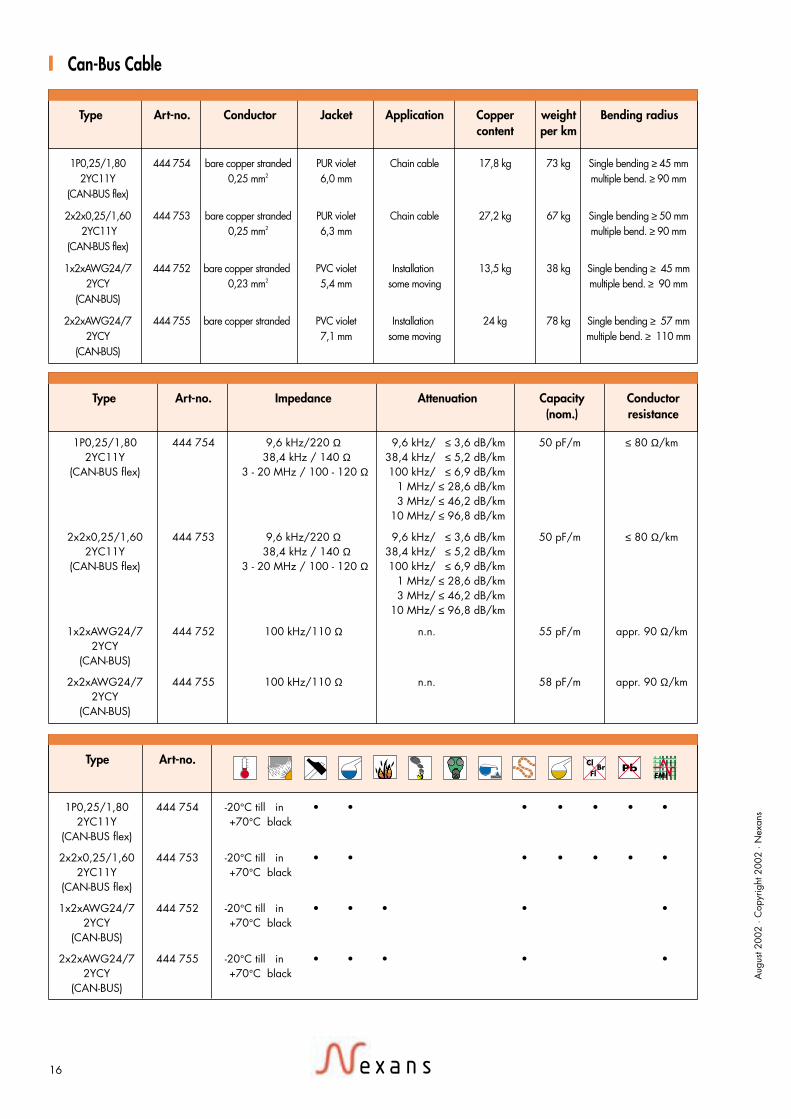
1P0,25/1,80 444 754 9,6 kHz/220 Ω 9,6 kHz/ ≤ 3,6 dB/km 50 pF/m ≤ 80 Ω/km2YC11Y 38,4 kHz / 140 Ω 38,4 kHz/ ≤ 5,2 dB/km
(CAN-BUS flex) 3 - 20 MHz / 100 - 120 Ω 100 kHz/ ≤ 6,9 dB/km1 MHz/ ≤ 28,6 dB/km3 MHz/ ≤ 46,2 dB/km
10 MHz/ ≤ 96,8 dB/km
2x2x0,25/1,60 444 753 9,6 kHz/220 Ω 9,6 kHz/ ≤ 3,6 dB/km 50 pF/m ≤ 80 Ω/km2YC11Y 38,4 kHz / 140 Ω 38,4 kHz/ ≤ 5,2 dB/km
(CAN-BUS flex) 3 - 20 MHz / 100 - 120 Ω 100 kHz/ ≤ 6,9 dB/km1 MHz/ ≤ 28,6 dB/km3 MHz/ ≤ 46,2 dB/km
10 MHz/ ≤ 96,8 dB/km
1x2xAWG24/7 444 752 100 kHz/110 Ω n.n. 55 pF/m appr. 90 Ω/km2YCY
(CAN-BUS)
2x2xAWG24/7 444 755 100 kHz/110 Ω n.n. 58 pF/m appr. 90 Ω/km2YCY
(CAN-BUS)
1P0,25/1,80 444 754 -20°C till in • • • • • • •2YC11Y +70°C black
(CAN-BUS flex)
2x2x0,25/1,60 444 753 -20°C till in • • • • • • •2YC11Y +70°C black
(CAN-BUS flex)
1x2xAWG24/7 444 752 -20°C till in • • • • •2YCY +70°C black
(CAN-BUS)
2x2xAWG24/7 444 755 -20°C till in • • • • •2YCY +70°C black
(CAN-BUS)
Can-Bus Cable
Type Art-no. Conductor Jacket Application Copper weight Bending radiuscontent per km
Aug
ust 2
002
· Cop
yrig
ht 2
002
· Nex
ans
16
1P0,25/1,80 444 754 bare copper stranded PUR violet Chain cable 17,8 kg 73 kg Single bending ≥ 45 mm2YC11Y 0,25 mm2 6,0 mm multiple bend. ≥ 90 mm
(CAN-BUS flex)
2x2x0,25/1,60 444 753 bare copper stranded PUR violet Chain cable 27,2 kg 67 kg Single bending ≥ 50 mm 2YC11Y 0,25 mm2 6,3 mm multiple bend. ≥ 90 mm
(CAN-BUS flex)
1x2xAWG24/7 444 752 bare copper stranded PVC violet Installation 13,5 kg 38 kg Single bending ≥ 45 mm2YCY 0,23 mm2 5,4 mm some moving multiple bend. ≥ 90 mm
(CAN-BUS)
2x2xAWG24/7 444 755 bare copper stranded PVC violet Installation 24 kg 78 kg Single bending ≥ 57 mm2YCY 7,1 mm some moving multiple bend. ≥ 110 mm
(CAN-BUS)
Type Art-no. Impedance Attenuation Capacity Conductor(nom.) resistance
Type Art-no.BrCl
Fl

Halogen free
BrClFl
Admissible ambienttemperature forcontinuous duty
operation
Fire retardant Low corrosivity
ApplicationsUsed to connect all types of sensorand adapter cables used withmachine tool and productionequipment. To be used withinharsh environment, highmechanical, oil and coatingagents.
Design(flexible version PUR)444750691. Conductor
tinned copper stranded0,34 mm2
2. InsulationPVC 1,45 mm
3. Twistingfour cores twisted together andhave overall a wrapped tape
4. Outer sheathPUR yellow 5,1 mm
MarkingSENSOR 3x0,34 PUR DESINA
Core Identificationwhite, blue, black, brown
Sensor CableNew development of insulation material with enhanced mechanical and electrical properties available.
Complete halogen free and flame retardant design with UL & CSA apptoval on request.
Oil resistance
Cable mechanicalresistance to
impacts
Electro magneticcompatibility
17
Resitance tosevere weather
conditions
Resistance tochemicals
Low smoke Low toxicity
Flexibility Lead free
StandardsAccording DESINA requirements
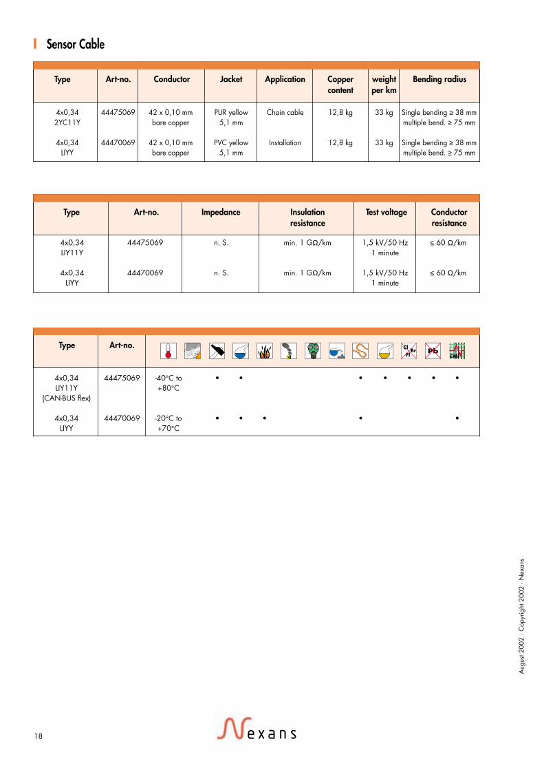
4x0,34 44475069 n. S. min. 1 GΩ/km 1,5 kV/50 Hz ≤ 60 Ω/kmLIY11Y 1 minute
4x0,34 44470069 n. S. min. 1 GΩ/km 1,5 kV/50 Hz ≤ 60 Ω/kmLIYY 1 minute
4x0,34 44475069 -40°C to • • • • • • •LIY11Y +80°C
(CAN-BUS flex)
4x0,34 44470069 -20°C to • • • • •LIYY +70°C
Sensor Cable
Type Art-no. Conductor Jacket Application Copper weight Bending radiuscontent per km
Aug
ust 2
002
· Cop
yrig
ht 2
002
· Nex
ans
18
4x0,34 44475069 42 x 0,10 mm PUR yellow Chain cable 12,8 kg 33 kg Single bending ≥ 38 mm2YC11Y bare copper 5,1 mm multiple bend. ≥ 75 mm
4x0,34 44470069 42 x 0,10 mm PVC yellow Installation 12,8 kg 33 kg Single bending ≥ 38 mmLIYY bare copper 5,1 mm multiple bend. ≥ 75 mm
Type Art-no. Impedance Insulation Test voltage Conductorresistance resistance
Type Art-no.BrCl
Fl