
Bulletin 825-P Modular Protection System · Quick Start Guide — Allen-Bradley Bulletin 825-P...
32
Quick Start Guide Bulletin 825-P Modular Protection System
Transcript of Bulletin 825-P Modular Protection System · Quick Start Guide — Allen-Bradley Bulletin 825-P...

Quick Start Guide
Bulletin 825-P Modular Protection System
Quick Start Guide — Allen-Bradley Bulletin 825-P Modular Protection System
2
Important User Information
Because of the variety of uses for the products described in this publication, those responsible for the application and use of this control equipment must satisfy themselves that all necessary steps have been taken to assure that each application and use meets all performance and safety requirements, including any applicable laws, regulations, codes, and standards.
The illustrations, charts, sample programs and layout examples shown in this guide are intended solely for purposes of example. Since there are many variables and requirements associated with any particular installation, Rockwell Automation does not assume responsibility or liability (to include intellectual property liability) for actual use based upon the examples shown in this publication.
Rockwell Automation publication SGI-1.1, Safety Guidelines for the Application, Installation and Maintenance of Solid-State Control (available from your local Allen-Bradley distributor), describes some important differences between solid-state equipment and electromechanical devices that should be taken into consideration when applying products such as those described in this publication.
Reproduction of the contents of this copyrighted publication, in whole or part, without written permission of Rockwell Automation, is prohibited.
Throughout this manual we use notes to make you aware of safety considerations.
:
IMPORTANT This guide Does Not replace the User Manual, publication 825-UM004_-EN-P, and is intended for qualified service personnel responsible for setting up and servicing these devices. You must have previous experience with and a basic understanding of electrical terminology, configuration procedures, required equipment, and safety precautions.
ATTENTION
!Identifies information about practices or circumstances that can lead to personal injury or death, property damage or economic loss.
Quick Start Guide — Allen-Bradley Bulletin 825-P Modular Protection System
33
Attention statements help you to:
• Identify a hazard• Avoid a hazard• Recognize the consequences
Trademark List
DeviceNet and the DeviceNet logo are trademarks of the Open Device Vendors Association (ODVA).
Microsoft Windows is a registered trademark of the Microsoft Corporation.
European Communities (EC)
Directive Compliance
The 825-P Modular Protection System is CE marked for installation within the European Union and EEA regions. It has been designed and tested to meet the following directives.
EMC Directive
This product is tested to meet the Council Directive 89/336/EEC Electromagnetic Compatibility (EMC) by applying the following standards, in whole:
• EN 60947-4-1 — Low-Voltage Switchgear and Controlgear: Part 4: Contactors and Motor Starters - Section 1: Electromechanical Contactors and Motor Starters
• EN 60947-5-1 — Low-Voltage Switchgear and Controlgear: Part 5: Control Circuit Devices and Switching Elements - Section 1: Electromechanical Control Circuit Devices
This product is intended for use in an industrial environment.
IMPORTANT Identifies information that is critical for successful application and understanding of the product.
TIP This product has been designed for environment A (heavy industrial). Use of this product in environment B (light industrial or domestic) can cause unwanted electromagnetic disturbances in which case the user could be required to take adequate mitigation measures.
Quick Start Guide — Allen-Bradley Bulletin 825-P Modular Protection System
4
Low Voltage Directive
This product is tested to meet Council Directive 73/23/EEC Low Voltage as amended by 93/68/EEC by applying the safety requirements of EN 60947-4-1 and EN 60947-5-1. For specific information required by EN 60947-4-1 and EN 60947-5-1, see the appropriate sections in this publication.
To obtain a copy of the 825-P’s Declaration of Conformity (DoC), contact your local Allen-Bradley distributor or go to http://www.ab.com.certification/#CEmark.
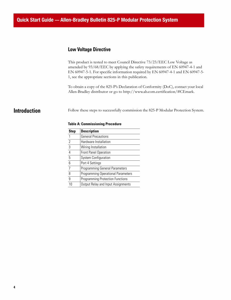
Introduction Follow these steps to successfully commission the 825-P Modular Protection System.
Table A: Commissioning Procedure
Step Description1 General Precautions2 Hardware Installation3 Wiring Installation4 Front Panel Operation5 System Configuration6 Port 4 Settings7 Programming General Parameters8 Programming Operational Parameters9 Programming Protection Functions10 Output Relay and Input Assignments
Quick Start Guide — Allen-Bradley Bulletin 825-P Modular Protection System
55
General Precautions
Hardware Installation
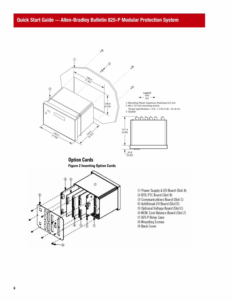
Relay MountingFigure 1 Mounting and Dimensions
ATTENTION
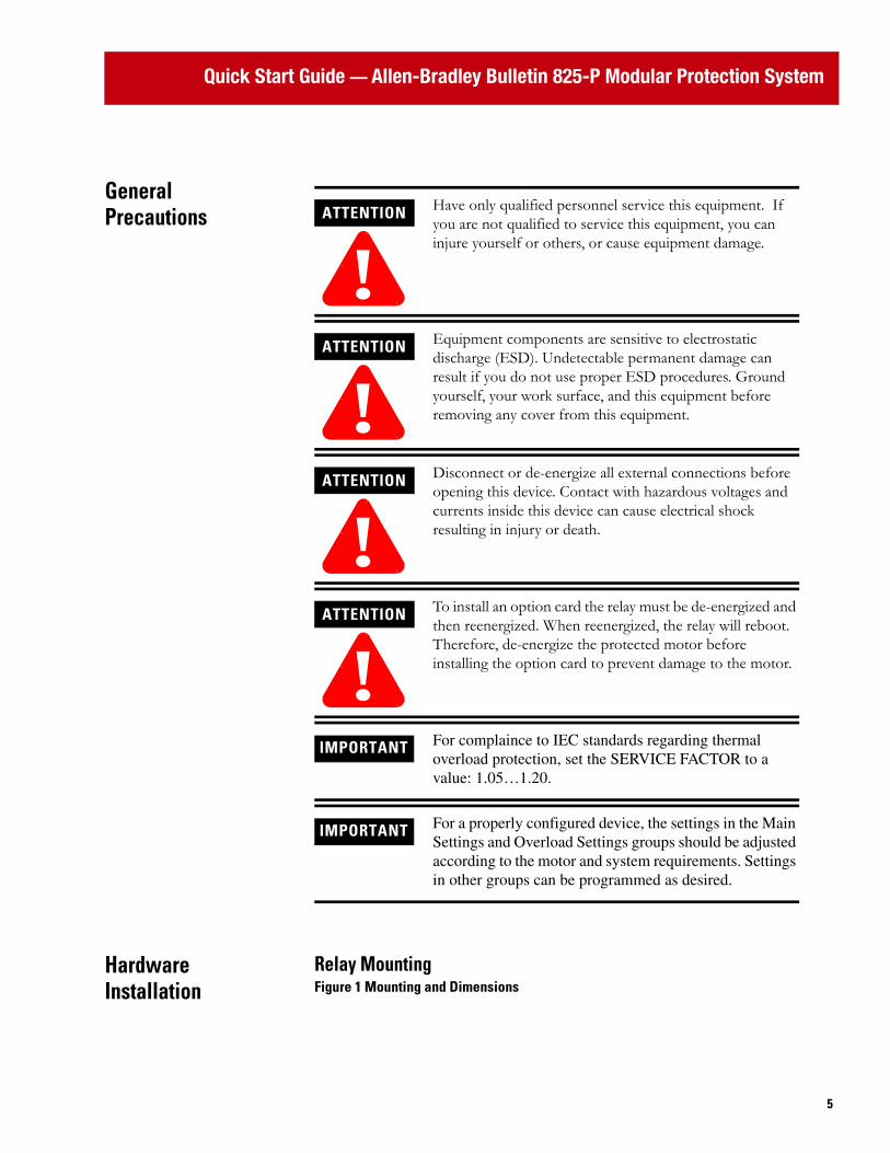
!Have only qualified personnel service this equipment. If you are not qualified to service this equipment, you can injure yourself or others, or cause equipment damage.
ATTENTION
!Equipment components are sensitive to electrostatic discharge (ESD). Undetectable permanent damage can result if you do not use proper ESD procedures. Ground yourself, your work surface, and this equipment before removing any cover from this equipment.
ATTENTION
!Disconnect or de-energize all external connections before opening this device. Contact with hazardous voltages and currents inside this device can cause electrical shock resulting in injury or death.
ATTENTION
!To install an option card the relay must be de-energized and then reenergized. When reenergized, the relay will reboot. Therefore, de-energize the protected motor before installing the option card to prevent damage to the motor.
IMPORTANT For complaince to IEC standards regarding thermal overload protection, set the SERVICE FACTOR to a value: 1.05…1.20.
IMPORTANT For a properly configured device, the settings in the Main Settings and Overload Settings groups should be adjusted according to the motor and system requirements. Settings in other groups can be programmed as desired.
Quick Start Guide — Allen-Bradley Bulletin 825-P Modular Protection System
6
Option CardsFigure 2 Inserting Option Cards
20.8(0.82)
147.4(5.80)
Legendmm(in)
192.0(7.56)
186.0(7.32)
138.0(5.43)
144.0
(5.67
)
➂
➀ Mounting Panel–maximum thickness 6.5 mm➁ #8 x 1/2 inch mounting screw; Torque specification = 0.9...1.3 N.m (8...12 Lb-in)➂ Gasket
➀➁

Quick Start Guide — Allen-Bradley Bulletin 825-P Modular Protection System
77
Converter Modules and Optional Core Balance CT, RTD ScannerFigure 3 Converter Module, CBCT, and RTD Scanner Connections
1. The 825-P relay is not EMC-Tested for converter module connecting cable lengths greater than the 4-meter cable that is supplied.
2. Up to 12 RTDs can be monitored when an external 825-PR12D RTD Scanner is used. There are separate trip and warning settings for each RTD.
3. A simplex 62.5/125 um fiber-optic cable with ST connector is needed for connecting the external RTD module to the 825-P. (Fiber optic cable is not supplied. Contact your local Allen-Bradley distributor.)
IMPORTANT Settings associated with options or accessories (converter module, voltage input card, expansion I/O card, RTD scanner) require their installation or connection prior to being made available for configuration.
Quick Start Guide — Allen-Bradley Bulletin 825-P Modular Protection System
8
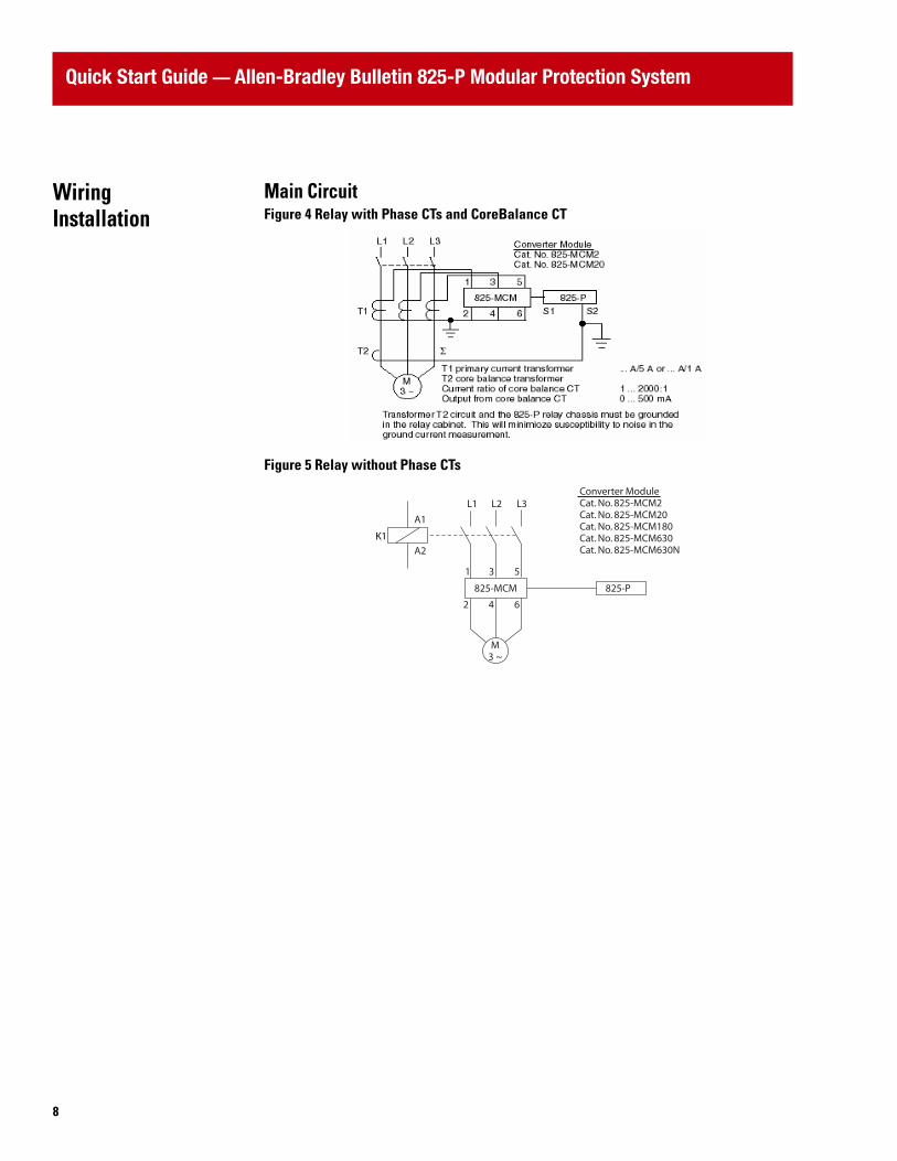
Wiring Installation
Main CircuitFigure 4 Relay with Phase CTs and CoreBalance CT
Figure 5 Relay without Phase CTs
K1
825-P825-MCM
L3L2L1
A1
1 3 5
642
A2
M3 ~
Converter ModuleCat. No. 825-MCM2Cat. No. 825-MCM20Cat. No. 825-MCM180Cat. No. 825-MCM630Cat. No. 825-MCM630N
Quick Start Guide — Allen-Bradley Bulletin 825-P Modular Protection System
99
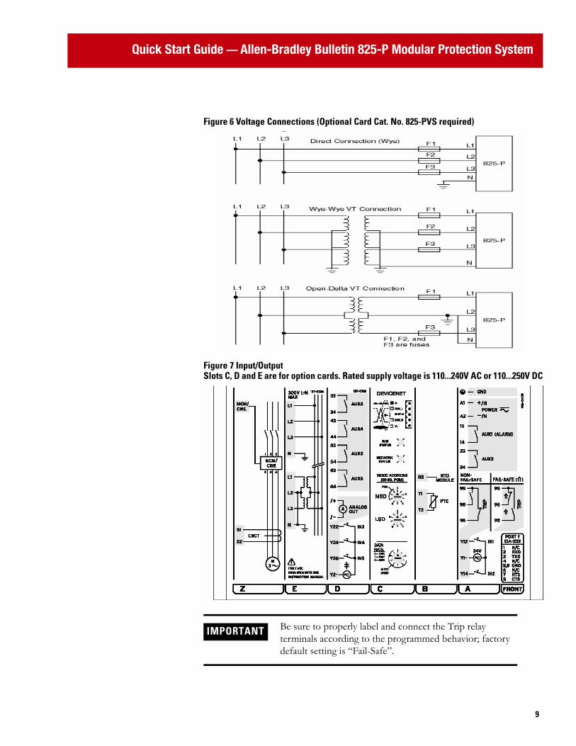
Figure 6 Voltage Connections (Optional Card Cat. No. 825-PVS required)
Figure 7 Input/OutputSlots C, D and E are for option cards. Rated supply voltage is 110...240V AC or 110...250V DC
IMPORTANT Be sure to properly label and connect the Trip relay terminals according to the programmed behavior; factory default setting is “Fail-Safe”.
Quick Start Guide — Allen-Bradley Bulletin 825-P Modular Protection System
10
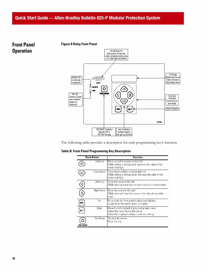
Front Panel Operation
Figure 8 Relay Front Panel
The following table provides a description for each programming key’s function.
Table B: Front Panel Programming Key Description
Quick Start Guide — Allen-Bradley Bulletin 825-P Modular Protection System
1111
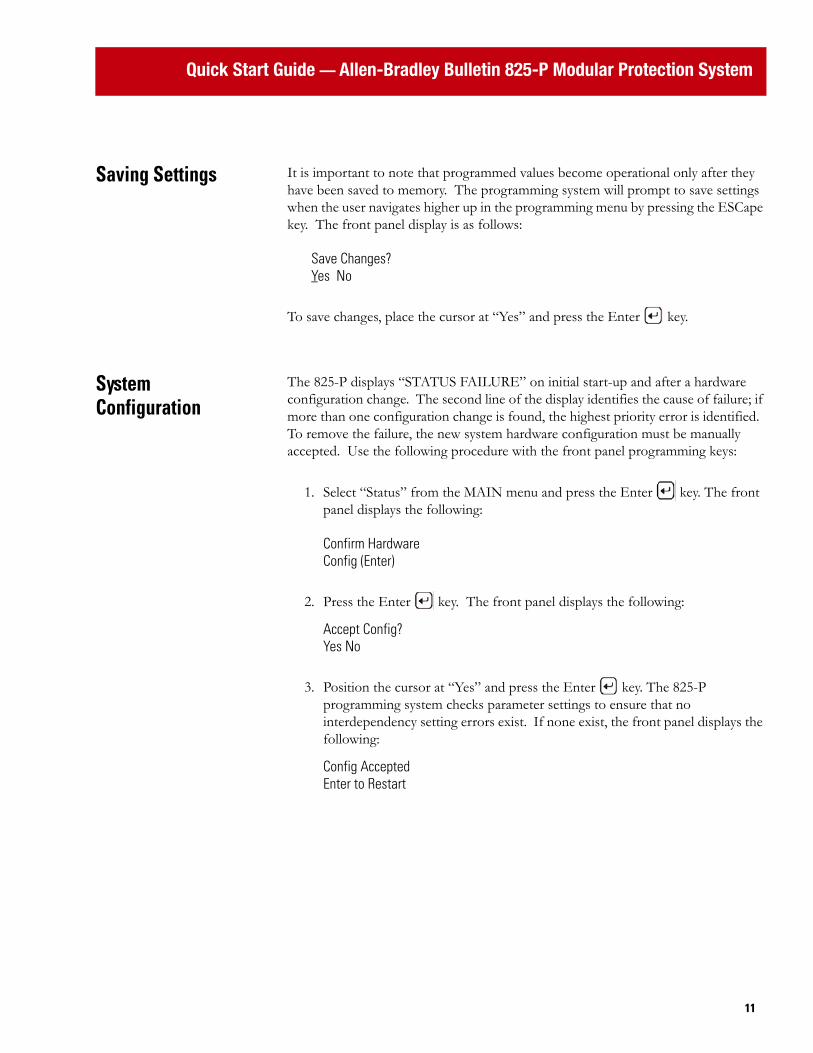
Saving Settings It is important to note that programmed values become operational only after they have been saved to memory. The programming system will prompt to save settings when the user navigates higher up in the programming menu by pressing the ESCape key. The front panel display is as follows:
Save Changes?Yes No
To save changes, place the cursor at “Yes” and press the Enter key.
System Configuration
The 825-P displays “STATUS FAILURE” on initial start-up and after a hardware configuration change. The second line of the display identifies the cause of failure; if more than one configuration change is found, the highest priority error is identified. To remove the failure, the new system hardware configuration must be manually accepted. Use the following procedure with the front panel programming keys:
1. Select “Status” from the MAIN menu and press the Enter key. The front panel displays the following:
Confirm HardwareConfig (Enter)
2. Press the Enter key. The front panel displays the following:
Accept Config?Yes No
3. Position the cursor at “Yes” and press the Enter key. The 825-P programming system checks parameter settings to ensure that no interdependency setting errors exist. If none exist, the front panel displays the following:
Config AcceptedEnter to Restart
Quick Start Guide — Allen-Bradley Bulletin 825-P Modular Protection System
12
4. Press the Enter key. The 825-P reboots and the “Enable” LED illuminates with the following displayed on the front panel.
825-P MODULARPROT SYSTEMIf the LCD display COMMFLT WARNING, configuration of the Port 4 is required. See next section.
IMPORTANT If the system check finds interdependency setting errors, the front panel display:
Settings Mismatch
An example of mismatched settings is the correlation between the Motor FLA and Phase CT Ratio settings. Review setting values to determine where the mismatch exists or, if little or no programming has been performed yet, reset the 825-P relay to factory default values using the following path:
MAIN > Reboot/Restore > Restore DefaultsThe front panel then displays:
Restore Default?No Yes
Position the cursor at “Yes” and press the Enter key. The 825-P relay will reboot at this point.
Return to the first step of the System Configuration process.

Quick Start Guide — Allen-Bradley Bulletin 825-P Modular Protection System
1313
Port 4 Settings The Port 4 settings configure slot C for communications. Factory default settings are for DeviceNet communications. Use the following path with the front panel programming keys to access the Port 4 settings:
MAIN > Set/Show > Port > Port 4
The following table provides direction for the proper settings associated with each communication option.
❶ A 232 setting is possible, although not typical.
Table C: Communication Settings
Setting Prompt Setting Range DeviceNet Modbus EmptyCOMM INTERFACE ❶ 232, 485 232 485 232PROTOCOL ASC, MOD MOD MOD MODSPEED 300 … 38,400 bps 19,200 19,200 19,200PARITY O, E, N N N NMODBUS SLAVE ID 1 … 248 248 1 to 247 1
IMPORTANT The 825-P displays “COMMFLT Warning” on initial power-up with factory default settings when the hardware installed in Slot C is as follows:
- Empty
- Modbus
- DeviceNet, but not powered
Quick Start Guide — Allen-Bradley Bulletin 825-P Modular Protection System
14
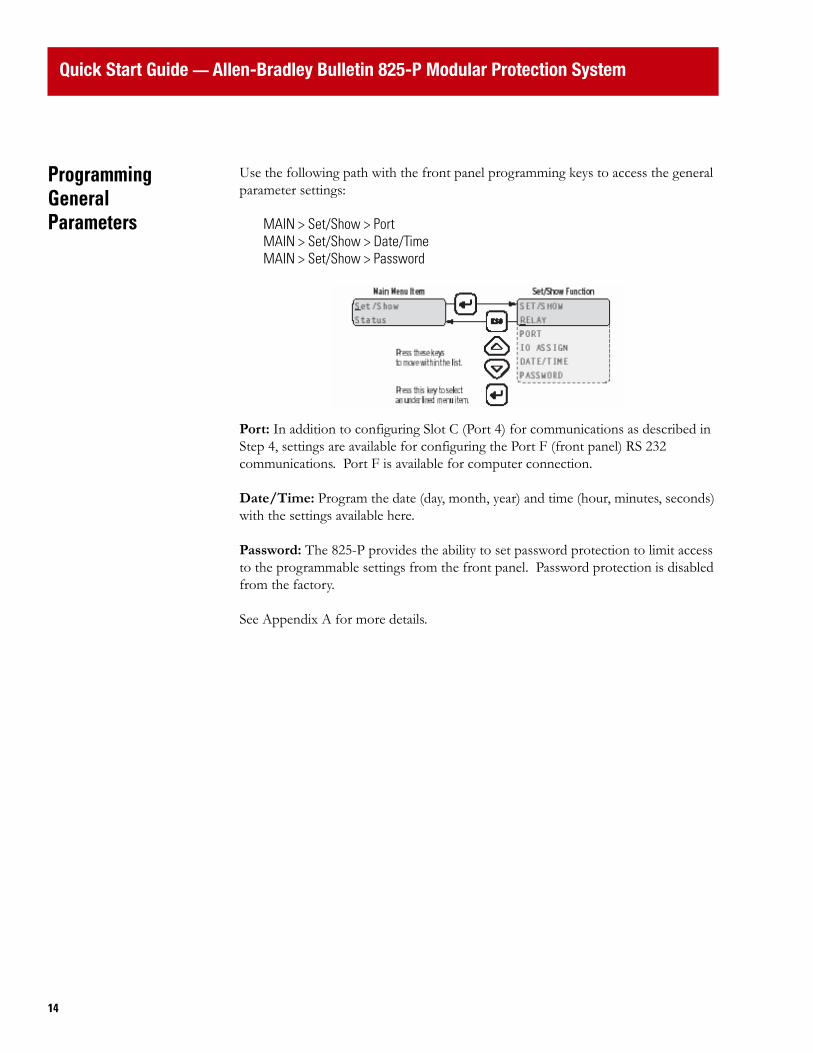
Programming General Parameters
Use the following path with the front panel programming keys to access the general parameter settings:
MAIN > Set/Show > PortMAIN > Set/Show > Date/TimeMAIN > Set/Show > Password
Port: In addition to configuring Slot C (Port 4) for communications as described in Step 4, settings are available for configuring the Port F (front panel) RS 232 communications. Port F is available for computer connection.
Date/Time: Program the date (day, month, year) and time (hour, minutes, seconds) with the settings available here.
Password: The 825-P provides the ability to set password protection to limit access to the programmable settings from the front panel. Password protection is disabled from the factory.
See Appendix A for more details.
Quick Start Guide — Allen-Bradley Bulletin 825-P Modular Protection System
1515
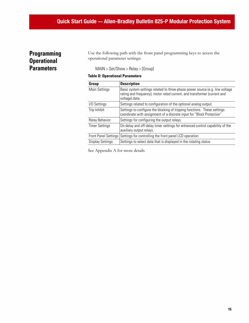
Programming Operational Parameters
Use the following path with the front panel programming keys to access the operational parameter settings:
MAIN > Set/Show > Relay > [Group]
See Appendix A for more details
Table D: Operational Parameters
Group DescriptionMain Settings Basic system settings related to three-phase power source (e.g. line voltage
rating and frequency), motor rated current, and transformer (current and voltage) data.
I/O Settings Settings related to configuration of the optional analog output.Trip Inhibit Settings to configure the blocking of tripping functions. These settings
coordinate with assignment of a discrete input for “Block Protection”. Relay Behavior Settings for configuring the output relays.Timer Settings On-delay and off-delay timer settings for enhanced control capability of the
auxiliary output relays.Front Panel Settings Settings for controlling the front panel LCD operation.Display Settings Settings to select data that is displayed in the rotating status

Quick Start Guide — Allen-Bradley Bulletin 825-P Modular Protection System
16
Programming Protection Parameters
Use the following path with the front panel programming keys to access the protection parameter settings:
MAIN > Set/Show > Relay > [Group]
See Appendix A for more details.
Output Relay and Input Assignments
After the operational and protection parameter values are set, the next step is to assign these functions to the relays.
Table E: Protection Parameters
Group DescriptionOverload Settings Thermal overload Short Ckt Settings Short circuitGF-CB Settings Ground/earth fault (core balance method)GF-Res Settings Ground/earth fault (residual method)Jam Settings Mechanical jam (overcurrent)Undercurrent Settings Current-based underload detectionCurrent Imb Settings Current imbalance (asymmetry)Prot. Disable Settings to disable protection elements during motor starting for a
user-specified time periodStart Monitoring Stall protection on motor start (current-time based)Star-Delta Settings Settings for star-delta controlStart Inhibt Set Settings for starts/hour and antibackspin Phase Rev Settings Phase reversal (sequence)Speed Sw Set Stall protection on motor start (speed switch input monitoring)PTC Settings Thermistor monitoring RTD Settings RTD settings for use with optional RTD ScannerUndervoltage Settings Voltage monitoring with optional voltage input cardOvervoltage Settings Voltage monitoring with optional voltage input cardVAR Settings Reactive powerUnderpower Settings Power-based underload detectionPower Factor Settings Displacement power factor monitoringFreq Settings Line frequency monitoringLoad Control Settings Settings for relay control based on motor loading

Quick Start Guide — Allen-Bradley Bulletin 825-P Modular Protection System
1717
To assign functions to the output relays and inputs, use the following path:
MAIN > Set/Show > IO Assign
ATTENTION
!Protection elements have no effect until they are assigned to the Trip relay or an auxiliary relay.
TIP The relay outputs will function as a N.C. contacts when the relay behavior setting is Fail-Safe (Y), and will function as a N.O. contacts when the relay behavior setting is Non-Fail-Safe (N).

Quick Start Guide — Allen-Bradley Bulletin 825-P Modular Protection System
18
Trip Relay Assign
The 825-P allows mapping of only protection trip elements to the Trip output relay. Settings are presented as bit-enumerated strings. The second line of the display identifies a given bit’s associated function. To assign a function to the Trip relay, simply program a value “1” in the bit location for each element you desire to assign using the TRIP A through TRIP D settings. The front panel display appears as follows:
TRIPA=10110000OVERLOAD
Table F: Trip Relay Settings
Bit0 1 2 3 4 5 6 7
TRIP A Overload Undercurrent Jam Current Imbalance
Short Circuit RTD - W/B PTC Ground Fault (Res)
TRIP B VAR Underpower Under-voltage
Over-voltage Phase Reversal
Power Factor Speed Switch
Ground Fault (CB)
TRIP C Start Time Freq 1 Freq 2 RTD (Other) RTD (Ambient)
PTC Error RTD Error MCM Error
TRIP D Comm Idle Comm Loss Remote Trip Comm Fault Reserved Reserved Reserved Reserved
TIP Make sure the Trip relay terminals (95, 96 and 98) are labeled to correspond with the relay behavior setting (Fail-Safe or Non-Fail-Safe).
Quick Start Guide — Allen-Bradley Bulletin 825-P Modular Protection System
1919
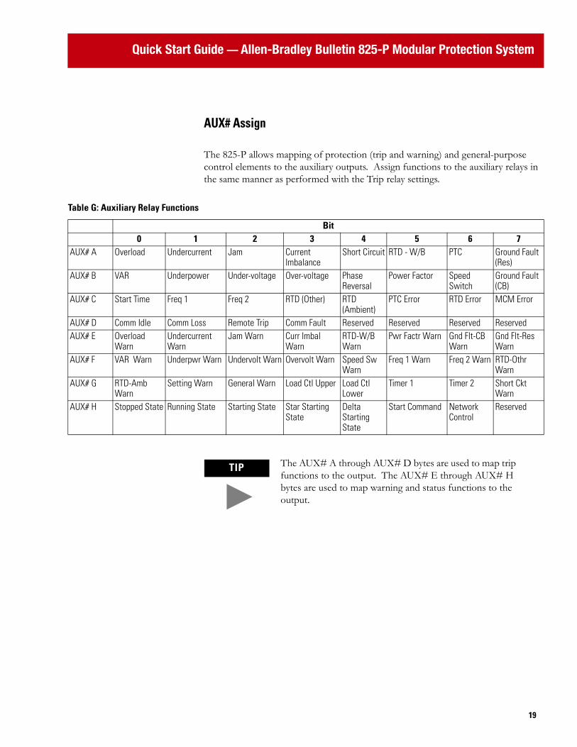
AUX# Assign
The 825-P allows mapping of protection (trip and warning) and general-purpose control elements to the auxiliary outputs. Assign functions to the auxiliary relays in the same manner as performed with the Trip relay settings.
Table G: Auxiliary Relay Functions
Bit0 1 2 3 4 5 6 7
AUX# A Overload Undercurrent Jam Current Imbalance
Short Circuit RTD - W/B PTC Ground Fault (Res)
AUX# B VAR Underpower Under-voltage Over-voltage Phase Reversal
Power Factor Speed Switch
Ground Fault (CB)
AUX# C Start Time Freq 1 Freq 2 RTD (Other) RTD (Ambient)
PTC Error RTD Error MCM Error
AUX# D Comm Idle Comm Loss Remote Trip Comm Fault Reserved Reserved Reserved ReservedAUX# E Overload
WarnUndercurrent Warn
Jam Warn Curr Imbal Warn
RTD-W/B Warn
Pwr Factr Warn Gnd Flt-CB Warn
Gnd Flt-Res Warn
AUX# F VAR Warn Underpwr Warn Undervolt Warn Overvolt Warn Speed Sw Warn
Freq 1 Warn Freq 2 Warn RTD-Othr Warn
AUX# G RTD-Amb Warn
Setting Warn General Warn Load Ctl Upper Load Ctl Lower
Timer 1 Timer 2 Short Ckt Warn
AUX# H Stopped State Running State Starting State Star Starting State
Delta Starting State
Start Command Network Control
Reserved
TIP The AUX# A through AUX# D bytes are used to map trip functions to the output. The AUX# E through AUX# H bytes are used to map warning and status functions to the output.

Quick Start Guide — Allen-Bradley Bulletin 825-P Modular Protection System
20
IN# Assign
The 825-P provides the ability to assign a control function to each discreet input. Table H shows the available control functions and the method of assigning them.
Analog Output
The expansion I/O option provides an isolated 4…20mA DC analog current output with a variety of output parameters. Use the Analog Output Select setting to select a parameter from the list of available options. Table I shows description and scaling of the output for different parameters selections.Table I:
Table H: Input Function Assignment
IN#0 Emergency Start1 Disable Settings2 Trip Reset3 Timer 14 Timer 25 Speed Switch6 Block Protection7 Speed 20 Breaker/Contactor Auxiliary1 Remote Trip
TIP The 825-P allows only one selection per input assignment. Once a selection is assigned, it is not available to other inputs.
Quick Start Guide — Allen-Bradley Bulletin 825-P Modular Protection System
2121
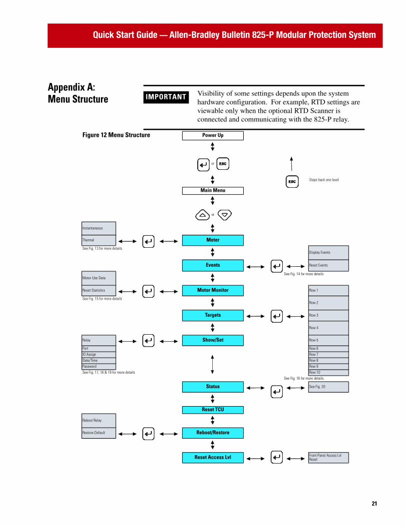
Appendix A: Menu Structure IMPORTANT Visibility of some settings depends upon the system
hardware configuration. For example, RTD settings are viewable only when the optional RTD Scanner is connected and communicating with the 825-P relay.
Figure 12 Menu Structure Power Up
or
Steps back one level
Main Menu
or
Instantaneous
Thermal Meter
See Fig. 13 for more details.Display Events
Events Reset Events
Motor Use DataSee Fig. 14 for more details
Reset Statistics Motor Monitor Row 1
See Fig. 15 for more detailsRow 2
Targets Row 3
Row 4
Relay Show/Set Row 5
Port Row 6IO Assign Row 7Date/Time Row 8Password Row 9See Fig. 17, 18 & 19 for more details Row 10
See Fig. 16 for more details.
Status See Fig. 20
Reset TCU
Reboot Relay
Restore Default Reboot/Restore
Reset Access Lvl Front-Panel Access Lvl Reset
Quick Start Guide — Allen-Bradley Bulletin 825-P Modular Protection System
22
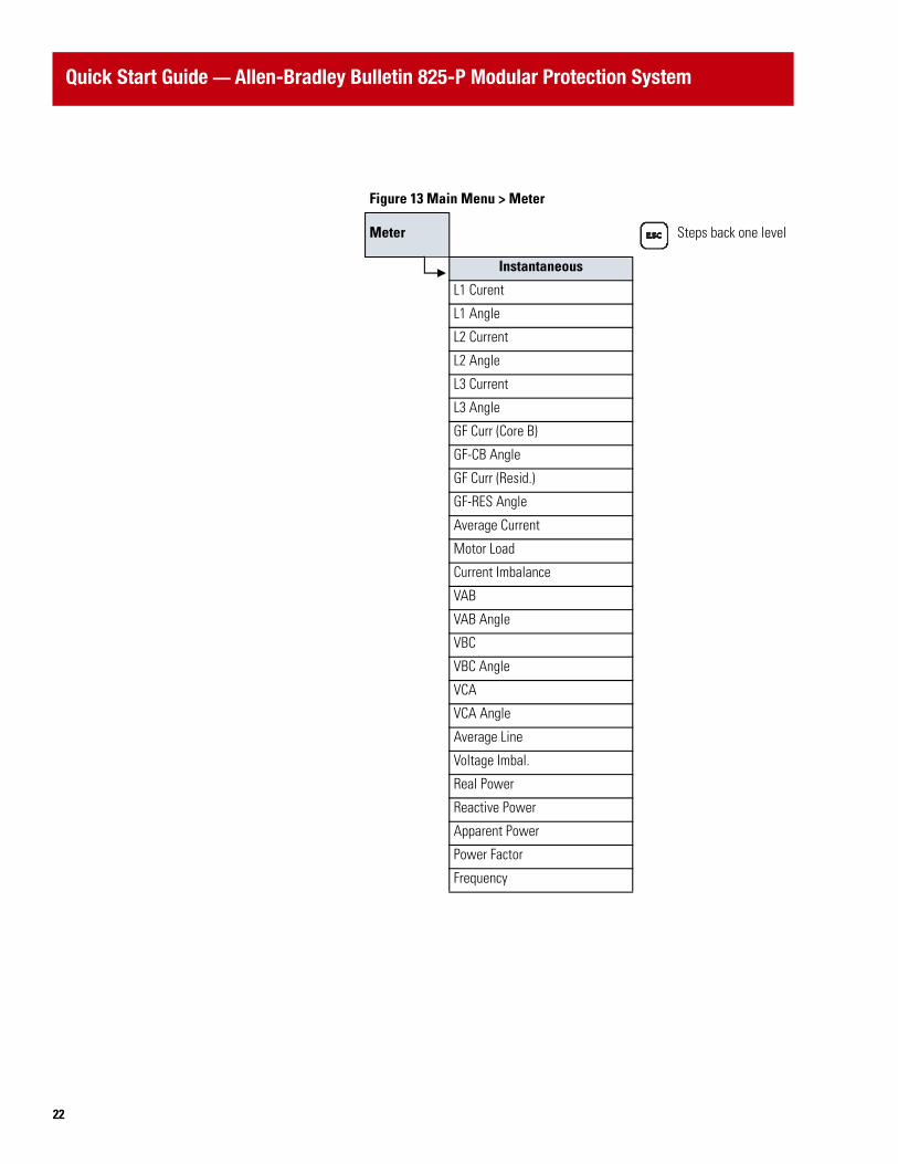
Figure 13 Main Menu > Meter
Meter Steps back one level
Instantaneous
L1 Curent
L1 Angle
L2 Current
L2 Angle
L3 Current
L3 Angle
GF Curr (Core B)
GF-CB Angle
GF Curr (Resid.)
GF-RES Angle
Average Current
Motor Load
Current Imbalance
VAB
VAB Angle
VBC
VBC Angle
VCA
VCA Angle
Average Line
Voltage Imbal.
Real Power
Reactive Power
Apparent Power
Power Factor
Frequency

Quick Start Guide — Allen-Bradley Bulletin 825-P Modular Protection System
2323
Figure 13 Main Menu > Meter
Meter Steps back one level
Thermal
Max Winding RTD
Max Bearing RTD
Ambient RTD
Max Other RTD
RTD1
RTD2
RTD3
RTD4
RTD5
RTD6
RTD7
RTD8
RTD9
RTD10
RTD11
RTD12
Motor Load
Therm Cap Used
RTD %TCU Used
Thermal Trip In
Time to Reset

Quick Start Guide — Allen-Bradley Bulletin 825-P Modular Protection System
24
Figure 14 Main Menu > Events
Events Steps back one level
Display Events
Date
Time
Type
Locked Rotor Torque
L1 Current
L2 Current
L3 Current
RES
CB
VAB
VBC
VCA
VG
Reset Events

Quick Start Guide — Allen-Bradley Bulletin 825-P Modular Protection System
2525
Figure 15 Main Menu > Motor Monitor
Motor Monitor Steps back one level
Motor Use Data
Last Reset Date
Last Reset Time
Running Time
Stopped Time
Time Running
Number of Starts
Emergency Starts
Reset Statistics

Quick Start Guide — Allen-Bradley Bulletin 825-P Modular Protection System
26
Figure 16 Main Menu > Targets Targets Steps back one level
Row 1 Row 649T (Overload Trip) VARA (VAR Warning)
LOSSTRIP (Undercurrent Trip) 37PA (Underpower Warning)
JAMTRIP (Jam Trip) 27P2T (Undervoltage Warning)
49UBT (Current Imbalance Trip) 59P2T (Overvoltage Warning)
50P1T (Short Circuit Trip) SPDSAL (Speed Switch Warning)
RTDT (RTD (Widing/Bearing) Trip) 81D1A (Frequency 1 Warning)
PTCTRIP (PTC Trip) 81D2A (Frequency 2 Warning)
50G1T (Ground Fault (Residual) Trip) OTHALRM (RTD (Other) Warning)
Row 2 Row 7VART (VAR Trip) AMBALRM (RTD (Ambient) Warning)
37PT (Underpower Trip) SALARM (Setting Warning)
27P1T (Undervoltage Trip) WARNING (General Warning)
59P1T (Overvoltage Trip) LOADUP (Load Control (Upper))
47T (Phase Reversal Trip) LOADLOW (Load Control (Lower))
55T (Power Factor Trip) TIMER1T (Timer 1)
SPDSTR (Speed Switch Trip) TIMER2T (Timer 2)
50N1T (Ground Fault (Core Balance) Trip) 50P2T (Short Circuit Warning)
Row 31 Row 8SMTRIP (Start Time Trip) STOPPED (Stopped State)
81D1T (Frequency 1 Trip) RUNNING (Running State)
81D2T (Frequency 2 Trip) STARTING (Starting State)
OTHTRIP (RTD (Other) Trip) STAR (Star (Wye) Starting State)
AMBTRIP (RTD (Ambient) Trip) DELTA (Delta Starting State)
PTCFLT (PTC Error Trip) START (Start Command)
RTDFLT (RTD Error Trip) Reserved
MCMFLT (MCM Error Trip) Reserved
Row 4 Row 9COMMIDLE (Comm Idle Trip) IN1 (Input 1 State)
COMMLOSS (Comm Loss Trip) IN2 (Input 2 State)
REMTRIP (Remote Trip) IN3 (Input 3 State)
COMMFLT (Comm Fault Trip) IN4 (Input 4 State)
Reserved IN5 (Input 5 State)
Reserved Reserved
Reserved Reserved
Reserved Reserved
Row 5 Row 1049A (Overload Warning) TRIP (Trip Relay State)
LOSSALRM (Undercurrent Warning) AUX1 (Auxiliary Relay 1 State)
JAMALRM (Jam Warning) AUX2 (Auxiliary Relay 2 State)
46UBA (Current Imbalance Warning) AUX3 (Auxiliary Relay 3 State)
RTDA (RTD (Winding/Bearing) Warning) AUX4 (Auxiliary Relay 4 State)
55A (Power Factor Warning) AUX5 (Auxiliary Relay 5 State)
50N2T (Ground Fault (Core Balance) Warning) AUX6 (Auxiliary Relay 6 State)
50G2T (Ground Fault (Core Balance) Warning) Reserved

Quick Start Guide — Allen-Bradley Bulletin 825-P Modular Protection System
2727
Figure 17 Main Menu > Show/SetShow/Set Steps back one level
RELAYPORT Main Settings
Overload Set
IO ASSIGN Short Ckt Set
TRIP RELAY ASSIGN GF-CB Settings
AUX1 ASSIGN GF-Res Settings
AUX2 ASSIGN Jam Settings
AUX3 ASSIGN Undercurrent Set
AUX4 ASSIGN Current Imb Set
IN1 ASSIGN Prot. Disable
IN2 ASSIGN Start Monitoring
Star-Delta Set
DATE/TIME Start Inhibt Set
DATE Speed Sw Set
TIME PTC Setting
RTD Setting
PASSWORD Undervoltage Set
New PW Overvoltage Set
VAR Settings
Underpower Set
Power Factor Set
Freq Settings
Phase Rev Set
Load Control Set
I/O Settings
Trip Inhibit
Relay Behavior
Timer Settings
Front Panel Set
Display Set

Quick Start Guide — Allen-Bradley Bulletin 825-P Modular Protection System
28
Figure 17 Main Menu > Show/Set
Port Steps back one level
PORT F
SPEED
DATA BITS
PARITY
STOP BITS
PORT TIMEOUT
HDWR HAND SHAKING
PORT 4
COMM INTERFACE
PROTOCOL
SPEED
PARITY
MODBUS SLAVE ID
Quick Start Guide — Allen-Bradley Bulletin 825-P Modular Protection System
2929
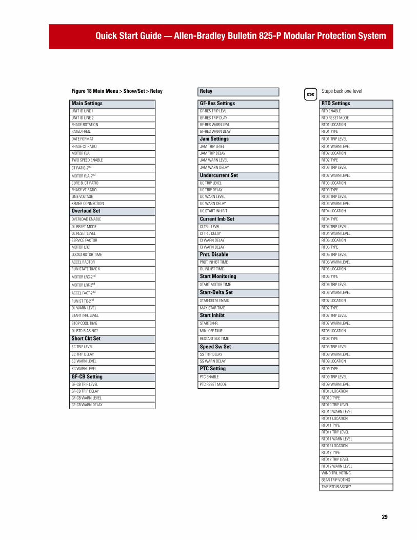
Figure 18 Main Menu > Show/Set > Relay Relay Steps back one level
Main Settings GF-Res Settings RTD SettingsUNIT ID LINE 1 GF-RES TRIP LEVL RTD ENABLE
UNIT ID LINE 2 GF-RES TRIP DLAY RTD RESET MODE
PHASE ROTATION GF-RES WARN LEVL RTD1 LOCATION
RATED FREQ. GF-RES WARN DLAY RTD1 TYPE
DATE FORMAT Jam Settings RTD1 TRIP LEVEL
PHASE CT RATIO JAM TRIP LEVEL RTD1 WARN LEVEL
MOTOR FLA JAM TRIP DELAY RTD2 LOCATION
TWO SPEED ENABLE JAM WARN LEVEL RTD2 TYPE
CT RATIO-2nd JAM WARN DELAY RTD2 TRIP LEVEL
MOTOR FLA-2nd Undercurrent Set RTD2 WARN LEVEL
CORE B. CT RATIO UC TRIP LEVEL RTD3 LOCATION
PHASE VT RATIO UC TRIP DELAY RTD3 TYPE
LINE VOLTAGE UC WARN LEVEL RTD3 TRIP LEVEL
XFMER CONNECTION UC WARN DELAY RTD3 WARN LEVEL
Overload Set UC START INHIBIT RTD4 LOCATION
OVERLOAD ENABLE Current Imb Set RTD4 TYPE
OL RESET MODE CI TRIL LEVEL RTD4 TRIP LEVEL
OL RESET LEVEL CI TRIL DELAY RTD4 WARN LEVEL
SERVICE FACTOR CI WARN DELAY RTD5 LOCATION
MOTOR LRC CI WARN DELAY RTD5 TYPE
LOCKD ROTOR TIME Prot. Disable RTD5 TRIP LEVEL
ACCEL RACTOR PROT INHIBT TIME RTD5 WARN LEVEL
RUN STATE TIME K OL INHIBT TIME RTD6 LOCATION
MOTOR LRC-2nd Start Monitoring RTD6 TYPE
MOTOR LRT-2nd START MOTOR TIME RTD6 TRIP LEVEL
ACCEL FACT-2nd Start-Delta Set RTD6 WARN LEVEL
RUN ST TC-2nd STAR-DELTA ENABL RTD7 LOCATION
OL WARN LEVEL MAX STAR TIME RTD7 TYPE
START INH. LEVEL Start Inhibt RTD7 TRIP LEVEL
STOP COOL TIME STARTS/HR. RTD7 WARN LEVEL
OL RTD BIASING? MIN. OFF TIME RTD8 LOCATION
Short Ckt Set RESTART BLK TIME RTD8 TYPE
SC TRIP LEVEL Speed Sw Set RTD8 TRIP LEVEL
SC TRIP DELAY SS TRIP DELAY RTD8 WARN LEVEL
SC WARN LEVEL SS WARN DELAY RTD9 LOCATION
SC WARN LEVEL PTC Setting RTD9 TYPE
GF-CB Setting PTC ENABLE RTD9 TRIP LEVEL
GF-CB TRIP LEVEL PTC RESET MODE RTD9 WARN LEVEL
GF-CB TRIP DELAY RTD10 LOCATION
GF-CB WARN LEVEL RTD10 TYPE
GF-CB WARN DELAY RTD10 TRIP LEVEL
RTD10 WARN LEVEL
RTD11 LOCATION
RTD11 TYPE
RTD11 TRIP LEVEL
RTD11 WARN LEVEL
RTD12 LOCATION
RTD12 TYPE
RTD12 TRIP LEVEL
RTD12 WARN LEVEL
WIND TRIL VOTING
BEAR TRIP VOTING
TMP RTD BIASING?

Quick Start Guide — Allen-Bradley Bulletin 825-P Modular Protection System
30
Figure 19 Main Menu > Show/Set > Relay Cont’d Relay Cont’d Steps back one
level
Undervoltage Set Load Control SetUV TRIP LEVEL LOAD CONTROL SEL
UV TRIP DELAY LD CTL CUR UPPER
UV WARN LEVEL LD CTL CUR LOWER
UV WARN DELAY LD CTL PWR UPPER
Overvoltage Set LD CTL PWR LOWER
OV TRIP LEVEL LD CTL TCU UPPER
OV TRIP DELAY LC CTL TCU LOWER
OV WARN LEVEL I/O SettingsOV WARN DELAY ANALOG OG OUT SEL
VAR Setting Trip InhibitNEG VAR TRIP CURRENT INBALANC
POS BAR TRIP JAM
VAR TRIP DELAY GROUND FAULT
NEG VAR WARN LEV SHORT CIRCUIT
PAS VAR WARN LEV UNDERCURRENT
VAR WARN DELAY START INHIBIT
Underpower Set PTC
UP TRIP LEVEL RTD
UP TRIP DELAY Relay BehaviorUP WARN LEVEL TRIP FAIL-SAFE
UP WARN DELAY AUX1 FAIL-SAFE
Power Factor Set AUX2 FAIL-SAFE
PF LAG TRIP LEVEL AUX3 FAIL-SAFE
PF LD TRIP LEVEL AUX4 FAIL-SAFE
PF TRIP DELAY AUX5 FAIL-SAFE
PF LAG WARN LEVEL AUX6 FAIL-SAFE
PF LD WARN LEVEL Timer SettingsPF WARN DELAY ON DELAY T1
Freq Settings OFF DELAY T1
FREQ1 TRIP LEVEL ON DELAY T2
FREQ1 TRIP DELAY OFF DELAY T2
FREQ1 WARN LEVEL Front Panel SetFREQ1 WARN DELAY LCD TIMEOUT
FREQ2 TRIP LEVEL LCD CONTRAST
FREQ2 TRIP DELAY Display SetFREQ2 WARN LEVEL TIME & DATE
FREQ2 WARN DELAY GROUND CURRENT
Phase Rev Set CURRENT IMBALANC
PH REV. ENABLE FREQUENCY
THERM CAP USED
VOLTAGE IMBALANC
POWER
RTD TEMPERATURE
Quick Start Guide — Allen-Bradley Bulletin 825-P Modular Protection System
3131
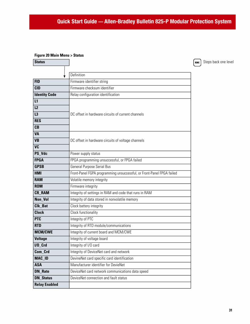
Figure 20 Main Menu > Status
Status Steps back one level
Definition
FID Firmware identifier string
CID Firmware checksum identifier
Identity Code Relay configuration identification
L1
DC offset in hardware circuits of current channels
L2
L3
RES
CB
VA
DC offset in hardware circuits of voltage channelsVB
VC
PS_Vdc Power supply status
FPGA FPGA programming unsuccessful, or FPGA failed
GPSB General Purpose Serial Bus
HMI Front-Panel FGPA programming unsuccessful, or Front-Panel FPGA failed
RAM Volatile memory integrity
ROM Firmware integrity
CR_RAM Integrity of settings in RAM and code that runs in RAM
Non_Vol Integrity of data stored in nonvolatile memory
Clk_Bat Clock battery integrity
Clock Clock functionality
PTC Integrity of PTC
RTD Integrity of RTD module/communications
MCM/CWE Integrity of current board and MCM/CWE
Voltage Integrity of voltage board
I/O_Crd Integrity of I/O card
Com_Crd Integrity of DeviceNet card and network
MAC_ID DevineNet card specific card identification
ASA Manufacturer identifier for DevieNet
DN_Rate DeviceNet card network communications data speed
DN_Status DeviceNet connection and fault status
Relay Enabled

Publication 825-QS001A-EN-P - August 2004© 2004 Rockwell International. All Rights Reserved. Printed in USA