Building Services: Project 1
162
B U I L D I N G S E R V I C E S CASE STUDY AND DOCUMENTATION OF BUILDING SERVICES SYSTEMS PJ TRADE CENTRE WATER SUPPLY SYSTEM ELECTRICAL SUPPLY SYSTEM SEWERAGE, SANITARY & DRAINAGE SYSTEM MECHANICAL TRANPORTATION SYSTEM MECHANICAL VENTILATIONAIR- CONDITIONING SYSTEM FIRE PROTECTION SYSTEM MOHD HASIF FAWWAZ SUKIMAN 0311561 FARAH FARHANAH KASSIM 0317534 NUR AIMAN MOHAMAD SHAKIR 0311759 NUR BAHIRAH ABDUL RAHMAN 0311085 RAHMAT AIDIL MAULA MD YUSOF 0311462
-
Upload
bahirah-rahman -
Category
Education
-
view
447 -
download
40
Transcript of Building Services: Project 1

B U I L D I N G S E R V I C E S
CASE STUDY AND DOCUMENTATION OF BUILDING SERVICES SYSTEMS
PJ TRADE CENTRE
WATER SUPPLY SYSTEM
ELECTRICAL SUPPLY SYSTEM
SEWERAGE, SANITARY & DRAINAGE SYSTEM
MECHANICAL TRANPORTATION SYSTEM
MECHANICAL VENTILATIONAIR-CONDITIONING SYSTEM
FIRE PROTECTION SYSTEM
MOHD HASIF FAWWAZ SUKIMAN 0311561
FARAH FARHANAH KASSIM 0317534
NUR AIMAN MOHAMAD SHAKIR 0311759
NUR BAHIRAH ABDUL RAHMAN 0311085
RAHMAT AIDIL MAULA MD YUSOF 0311462

2
CONTENTS
1.O INTRODUCTION
1.1 Abstract 1.2 Acknowledgement
2.0 ELECTRICAL SUPPLY SYSTEMS
2.1 Introduction
2.2 Literature Review 2.3 Electrical Supply System by Law (UBBL)
2.4 Electrical Components 2.5 Case Study and analysis
2.6 Conclusion
3.0 WATER SUPPLY SYSTEMS
3.1 Introduction 3.2 Literature Review
3.3 Water Supply By Law 3.4 Case Study
3.5 Analysis
4.0 FIRE PROTECTION SYSTEMS
4.1 Literature Review 4.2 Active Fire Protection System
4.3 Passive Fire Protection System 4.4 Analysis
5.0 MECHANICAL TRANSPORTATION
SYSTEMS
5.1 Introduction 5.2 Literature Review
5.3 Case Study 5.4 Safety Devices
5.5 Elevator Control System 5.6 Special Operating Modes
5.7 Location 5.8 UBBL Requirements
5.9 Analysis

3
6.0 MECHANICAL VENTILATION AND AIR CONDITIONING SYSTEMS
6.1 Prologue
6.2 Introduction and function 6.3 Components of System
6.4 Types and Function of Air Conditioning System 6.5 Components of the Split Unit Air Conditioning
System 6.6 Operation of system
6.7 UBBL Requirements and Related Regulation 6.8 Conclusion
7.0 SANITARY AND SEWERAGE SYSTEMS
7.1 Introduction 7.2 Case Study
7.3 Irrigation Systems 7.4 Filtration Systems
7.5 UBBL Requirement 7.6 Analysis
8.0 CONCLUSION
9.0 REFERENCES
4
1.0 INTRODUCTION

5
1.0 INTRODUCTION
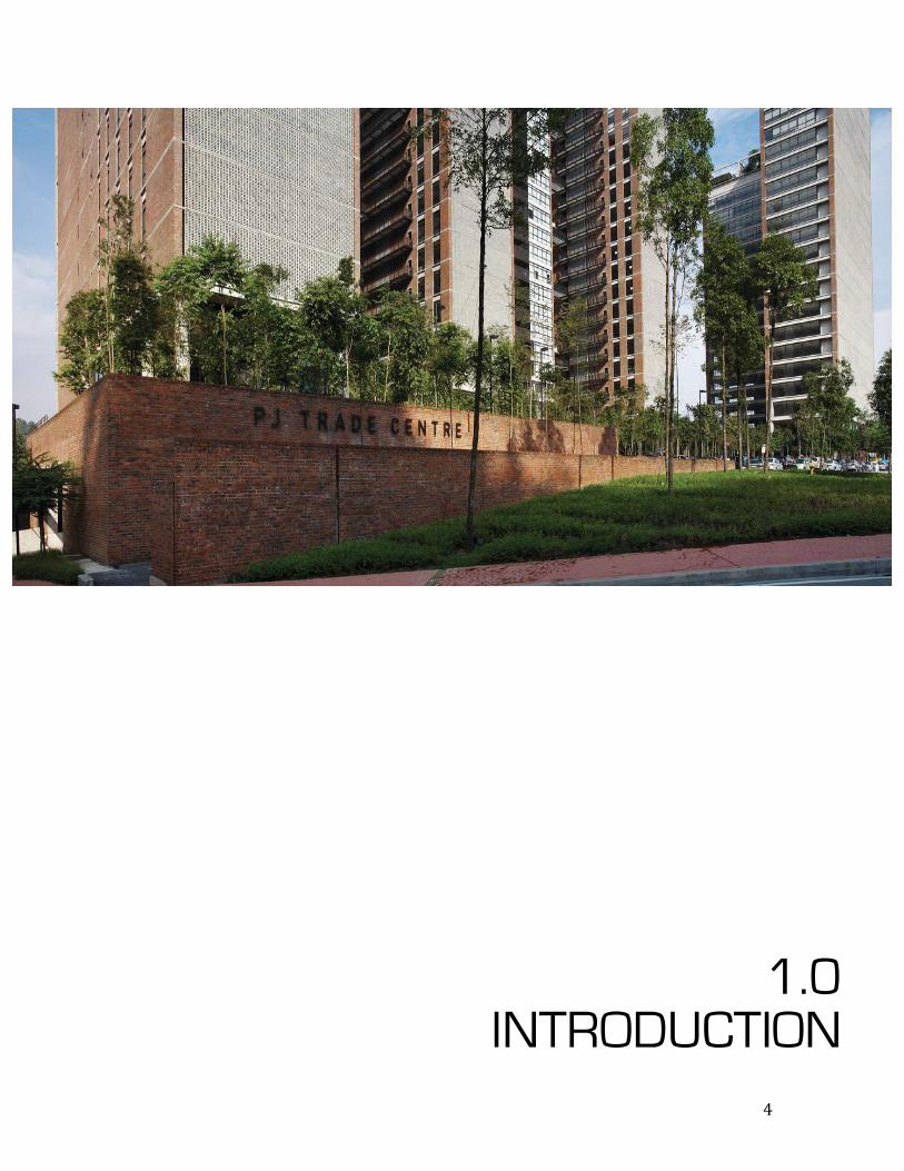
A MALAYSIA PARADIGM “With PJTC, the idea was to offer a new paradigm for office
development. It is based on the use of simple local materials and
local construction methods to create an office development that is
suited to the local culture, climate and context.”
Well said by the developer himself, TujuanGemilangSdn. Bhd.
PJ Trade Centre was completed and designed by our very own
Malaysian developer, TujuanGemilangSdn. Bhd. It has been
completed in the month of February 2009. PJ Trade Centre is
located in the Golden Triangle of PJ, a dynamic centre for
entertainment, business, and shopping. The idea behind it was to
take a leap of faith where being different with other but at the same
time it suits with the climate, culture and the environment
surrounding. However, Seksan Design was the one who designed
the surrounding landscape.
6
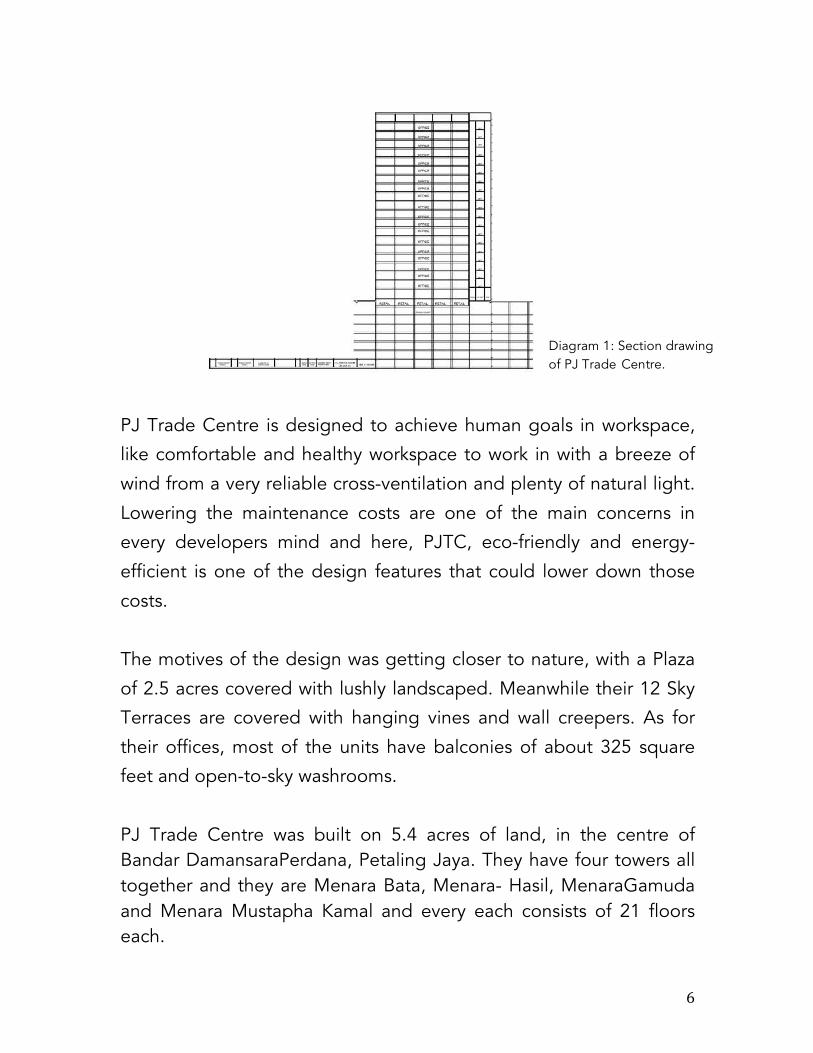
PJ Trade Centre is designed to achieve human goals in workspace,
like comfortable and healthy workspace to work in with a breeze of
wind from a very reliable cross-ventilation and plenty of natural light.
Lowering the maintenance costs are one of the main concerns in
every developers mind and here, PJTC, eco-friendly and energy-
efficient is one of the design features that could lower down those
costs.
The motives of the design was getting closer to nature, with a Plaza
of 2.5 acres covered with lushly landscaped. Meanwhile their 12 Sky
Terraces are covered with hanging vines and wall creepers. As for
their offices, most of the units have balconies of about 325 square
feet and open-to-sky washrooms.
PJ Trade Centre was built on 5.4 acres of land, in the centre of Bandar DamansaraPerdana, Petaling Jaya. They have four towers all together and they are Menara Bata, Menara- Hasil, MenaraGamuda and Menara Mustapha Kamal and every each consists of 21 floors each.
Diagram 1: Section drawing of PJ Trade Centre.

7
1.1 ABSTRACT
The case study report will be focusing into the settings of the
services system in the PJ Trade Centre such as the Air conditioning
and ventilation systems, Fire safety system, Electricity supply system,
Water supply system, the Sewerage system and Mechanical
Transportation system. The report are aiming at introducing the
fundamentals of all the mentioned systems as well as an analysis of
the system that have been analyzed and synthesized to our own
understanding and also based on the regulations of buildings and its
services such as Uniform Building By Law and also Malaysian
Standards. Requirements and adherence will also be analyzed based
on each services respected controlling arm.
1.2 ACKNOWLEDGEMENT
This project consumed a huge amount of work, research and
dedication. The implementation would not been possible without
the support and guidance of many people involved. Therefore, we
would like to extend our huge gratitude to the people who has
helped and assisting us to complete this research report. Without
their involvement and guidance, this report would be insufficient and
substandard.
Special thanks we would like to give to our lectures, Mr. Rizal and Ms
AR. Sateerah Hassan for the guidance through every each tutorial
and providing us with an aim and goals to accomplish.
We are also grateful for having the humble staffs at PJ Trade Centre
and especially to Mr. Suresh for welcoming and willingly giving us an

8
opportunity to explore more of the services system incorporated into
the building.

9
2.0 ELECTRICAL
SUPPLY SYSTEMS

10
2.1 INTRODUCTION This chapter explains on the basic and general study of the electrical
supply system at PJ Trade Centre, focusing on Tower B. The
information mentioned is linked with the case study regarding how
the electrical supply is distributed throughout the whole building of
Block B.
The electrical supply system case study will be covered to include
the electrical power supply system, electrical components, the study
on the function of the electrical rooms, the basic design
considerations and dimensions. The findings are concluded in a
diagram to give a brief understanding on how electrical supply
system works at PJ Trade Centre. 2.2 LITERATURE REVIEW Electricity was never invented. Its properties were discovered,
examined, and explained. The conveyance of electric power is
coming from a power station to consumers’ premises, which is
known as electric supply system. An electric supply system consists
of three principal components, which are the power station, the
transmission lines and the distribution system. The electric supply
systems can broadly classified ino D.C. (Direct Current) or A.C.
(Alternating Current) system and overhead or underground system.

11
Nowadays, 3-phase and 3-wire A.C. system is universally
adopted for generation and transmission of electric power as an
economical proposition. Below is the typical A.C. Power Supply
Scheme (Diagram 2.1):
Figure 2.2.1
The network can be broadly divided into two parts:-
1. transmission system and
2. distribution system.
Each part can be further subdivided into two which are the
primary transmission and secondary transmission and primary
distribution and secondary distribution.
Diagram 2.2.2
12
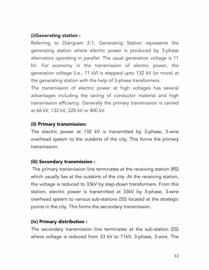
(i)Generating station : Referring to Diangram 2.1, Generating Station represents the
generating station where electric power is produced by 3-phase
alternators operating in parallel. The usual generation voltage is 11
kV. For economy in the transmission of electric power, the
generation voltage (i.e., 11 kV) is stepped upto 132 kV (or more) at
the generating station with the help of 3-phase transformers.
The transmission of electric power at high voltages has several
advantages including the saving of conductor material and high
transmission efficiency. Generally the primary transmission is carried
at 66 kV, 132 kV, 220 kV or 400 kV.
(ii) Primary transmission: The electric power at 132 kV is transmitted by 3-phase, 3-wire
overhead system to the outskirts of the city. This forms the primary
transmission.
(iii) Secondary transmission : The primary transmission line terminates at the receiving station (RS)
which usually lies at the outskirts of the city. At the receiving station,
the voltage is reduced to 33kV by step-down transformers. From this
station, electric power is transmitted at 33kV by 3-phase, 3-wire
overhead system to various sub-stations (SS) located at the strategic
points in the city. This forms the secondary transmission.
(iv) Primary distribution : The secondary transmission line terminates at the sub-station (SS)
where voltage is reduced from 33 kV to 11kV, 3-phase, 3-wire. The

13
11 kV lines run along the important road sides of the city. This forms
the primary distribution. It may be noted that big consumers (having
demand more than 50 kW) are generally supplied power at 11 kV for
further handling with their own sub-stations.
(v) Secondary distribution : The electric power from primary distribution line (11 kV) is delivered
to distribution sub-stations (DS). These sub-stations are located near
the consumers’ localities and step down the voltage to 400 V, 3-
phase, 4-wire for secondary distribution. The voltage between any
two phases is 400 V and between any phase and neutral is 230 V.
The single-phase residential lighting load is connected between any
one phase and neutral, whereas 3-phase, 400 V motor load is
connected across 3-phase lines directly.
2.3 ELECTRICAL SUPPLY SYSTEM (UNIFORM BUILDING BY
LAW) (Licensed to Malaysian Standard MS1525: 2014)
The purpose for this Malaysian Standard in terms of power
distribution system is to minimize losses in electrical power
distribution and equipment efficiency. Some of the laws are below:
• Power Factor Correction Capacitors

14
Power factor correction capacitors should be the low loss type with
losses per kVAR not exceeding 0.35 W at upper temperature limit
excluding the losses in the discharge resistors.
• Sub Metering
To facilitate monitoring of energy consumption and energy
management, electrical energy meters should be installed at
strategic load centers to identify consumption by functional use (air
conditioning, lighting, etc.).
The electricity supply and installation practice in Peninsular
Malaysia are governed by the following: -
1. Electricity Supply Act 1990 – Act 447
2. Licensed Supply Regulations 1990
3. Electricity Regulations 1994
4. Customer Charter – refer to TNB website (www.tnb.com.my)
2.4 ELECTRICAL COMPONENTS
Designers must know that electrical systems are significant in
today’s world and it is crucial that they do not fail. Electrical
components generally do not wear out easily. They tend to drift over
time and can cause problems with sensitive designs. It is a concern
when combined with environmental effects, transient stress,
corrosion, vibration and temperature. The electrical components
found in PJ Trade Centre are divided into three catagories:

15
• Active
An active component works as an alternating-current circuit in a
device, which works to increase the active power, voltage or current.
An active component is able to do this because it is powered by a
source of electricity that is separated from the electrical signal.
i. Semiconductors
ii. Display Technologies
iii. Discharge Devices
iv. Power Sources
• Passive
Passive components are those that do not require electrical power to
operate and store or maintain energy in the form of voltage or
current.
i. Resistors
ii. Capacitors
iii. Magnetic Devices
iv. Transducers, sensors, detectors
• Electromechanical Electromechanical component carries out its electrical operations by
using moving parts or electrical connections.
i. Terminals and Connectors
ii. Cable Assemblies
iii. Switches
iv. Protection Devices

16
2.4.1 ACTIVE COMPONENTS
Semiconductors
1. Diodes
Figure 2.4.1 Diode
The function of a diode is to sanction an electric current to pass in
one direction (called the diode's forward direction), while blocking
current in the antithesis direction (the inversion direction). Thus, the
diode can be viewed as an electronic version of a check valve.
2. Transistors

17
Figure 2.4.2 Transistors
A transistor is a semiconductor contrivance used to amplify and
switch electronic signals and electrical puissance. Manufacturers
withal make PNP junction transistors. In these contrivances, the
emitter and collector are both a p-type semiconductor material and
the base is n-type. A PNP junction transistor works on the same
principle as an NPN transistor. But it differs in one reverence.
3. Intergrated Circuit
Figure 2.4.3 Intergrated Circuit
An integrated circuit (IC), sometimes called a chip or microchip, is a
semiconductor wafer on which thousands or millions of minuscule
resistors, capacitors, and transistors are fabricated. An IC can
function as an amplifier, oscillator, timer, counter, computer
recollection, or microprocessor.
Display Technologies
1. LCD

18
Figure 2.4.4 LCD
A liquid-crystal exhibit (LCD) is a flat panel exhibit, electronic visual
exhibit, or video exhibit that utilizes the light modulating properties
of liquid crystals. Liquid crystals do not emit light directly. LCDs are
available to exhibit arbitrary images (as in a general-purport
computer exhibit) or fine-tuned images which can be exhibited or
obnubilated, such as preset words, digits, and 7-segment exhibits as
in a digital clock.
2. LED
Figure 2.4.5 LED component

19
A light-emitting diode (LED) is a two-lead semiconductor light
source. It is a pn-junction diode, which emits light when activated.
When a felicitous voltage is applied to the leads, electrons are able
to recombine with electron apertures within the contrivance,
relinquishing energy in the form of photons. This effect is called
electroluminescence, and the color of the light (corresponding to the
energy of the photon) is resolute by the energy band gap of the
semiconductor. An LED is often minute in area (less than 1 mm2) and
integrated optical components may be habituated to shape its
radiation pattern.
Discharge Devices
1. Gas Discharge Tube
Figure 2.4.6 Gas Discharge Tube
A gas discharge tube, or GDT, is a glass-enclosed contrivance that is
sealed and that contains a special gas amalgamation which is
trapped between two electrodes. Gas discharge tubes conduct
electrical current after they become ionized by a high voltage spike,
can conduct a relatively high amount of current for their size and can
handle some profoundly and astronomically immense transients or
several more diminutive transients. Gas discharge tubes withal take a

20
long time to trigger, which sanctions a higher voltage spike to pass
through afore conducting a paramount amount of current.
Power Sources
1. Electrical Generator
Figure 2.4.7 Electrical Generator
In electricity generation, an engenderer is a contrivance that converts
mechanical energy to electrical energy for use in an external circuit.
The source of mechanical energy may vary widely from a hand crank
to an internal combustion engine. Engenderers provide proximately
all of the potency for electric power grids.
2. Power Supply

21
Figure 2.4.8 Power Supply
A power supply is an electronic contrivance that supplies electric
energy to an electrical load. The primary function of a power supply
is to convert one form of electrical energy to another and, as a result,
power supplies are sometimes referred to as electric power
converters. Some power supplies are discrete, stand-alone
contrivances, whereas others are built into more astronomically
immense contrivances along with their loads.
2.4.2 PASSIVE COMPONENTS
Resistors
1. Resistor

22
Figure 2.4.9 Resistor
A resistor is a passive two-terminal electrical component that
implements electrical resistance as a circuit element. Resistors act to
reduce current flow, and, concurrently, act to lower voltage levels
within circuits. In electronic circuits resistors are habituated to inhibit
current flow, to adjust signal levels, inequitableness active elements,
terminate transmission lines among other uses. High-power resistors
that can dissipate many watts of electrical power as heat may be
utilized as a component of motor controls, in power distribution
systems, or as test loads for engenderers. Fine-tuned resistors have
resistances that only change scarcely with temperature, time or
operating voltage.
2. Rheostat
Figure 2.4.10 Rheostat

23
A rheostat is a variable resistor. The most common way to vary the
resistance in a circuit is to use a rheostat. Variable resistors can be
habituated to adjust circuit elements (such as a volume control or a
lamp dimmer), or as sensing contrivances for heat, light, sultriness,
force, or chemical activity.
Capasitors
1. Capacitor
Figure 2.4.11 Capasitor
A capacitor (pristinely kenned as a condenser) is a passive two-
terminal electrical component used to store energy electrostatically
in an electric field. The forms of practical capacitors vary widely, but
all contain at least two electrical conductors (plates) dissevered by a
dielectric (i.e. insulator). The conductors can be thin films, foils or
sintered beads of metal or conductive electrolyte, etc. The
nonconducting dielectric acts to increment the capacitor's charge
capacity. Capacitors are widely utilized as components of electrical
circuits in many prevalent electrical contrivances.
Magnetic Devices

24
1. Inductor
Figure 2.4.12 Inductor
An inductor is a passive two-terminal electrical component which
resists vicissitudes in electric current passing through it. It consists of
a conductor such as a wire, conventionally wound into a coil. When a
current permeates it, energy is stored transitory in a magnetic field in
the coil. When the current permeating an inductor changes, the
time-varying magnetic field induces a voltage in the conductor,
according to Faraday’s law of electromagnetic induction, which
opposes the transmutation in current that engendered it.
Tranducers, sensors, detectors
1. Tranducers

25
Figure 2.4.13 Transducer
A transducer is a contrivance that converts one form of energy to
another form of energy. Energy types include/(but are not inhibited
to) electrical, mechanical, electromagnetic, chemical, acoustic, and
thermal energy. Customarily a transducer converts a signal in one
form of energy to a signal in another, but any variable attenuation of
energy may accommodate as input.
2. Sensors
Figure 2.4.14 Sensor
A sensor is a transducer whose purport is to sense some
characteristic of its environs. It detects events or transmutations in
quantities and provides a corresponding output, generally as an
electrical or optical signal; for example, a thermocouple converts
temperature to an output voltage. But a mercury-in-glass
thermometer is additionally a sensor; it converts the quantified
temperature into expansion and contraction of a liquid which can be
read on a calibrated glass tube.

26
2.4.3 ELECTROMECHANICAL
Terminals and Connectors
1. Terminal
Figure 2.4.15 Electronic terminal
A terminal is the point at which a conductor from an electrical
component, contrivance or network comes to a cessation and
provides a point of connection to external circuits. A terminal may
simply be the cessation of a wire or it may be fitted with a connector
or fastener. In network analysis, terminal betokens a point at which
connections can be made to a network in theory and does not
compulsorily refer to any authentic physical object. In this context,
especially in older documents, it is sometimes called a pole.
2. Connector

27
Figure 2.4.16 Connector
An electrical connector is an electro-mechanical contrivance for
joining electrical circuits as an interface utilizing a mechanical
assembly. Connectors consist of plugs (male-ended) and jacks
(female-ended). The connection may be ad interim, as for portable
equipment, require an implement for assembly and abstraction, or
accommodate as a sempiternal electrical joint between two wires or
contrivances. An adapter can be habituated to efficaciously assemble
dissimilar connectors.
Switches
1. Switch
Figure 2.4.17 Switch

28
A switch is an electrical component that can break an electrical
circuit, interrupting the current or diverting it from one conductor to
another. The mechanism of a switch may be operated directly by a
human operator to control a circuit (for example, a light switch or a
keyboard button), may be operated by a moving object such as a
door-operated switch, or may be operated by some sensing element
for pressure, temperature or flow.
Cable assemblies
1. Power Cord
Figure 2.4.18 Power Chord
A power cord, line cord, or mains cable is a cable that transitory
connects an appliance to the mains electricity supply via a wall
socket or extension cord. The terms are generally utilized for cables
utilizing a potency plug to connect to a single-phase alternating
current power source at the local line voltage—(generally 100 to 240
volts, depending on the location). The terms power cable, mains
lead, flex or kettle lead are additionally utilized.

29
Protection Devices
1. Fuse
Figure 2.4.19 Fuse
In electronics and electrical engineering, a fuse (from the French
fusée, Italian fuso, "spindle"[1]) is a type of low resistance resistor
that acts as a sacrificial contrivance to provide overcurrent auspice,
of either the load or source circuit. Its essential component is a metal
wire or divest that melts when an extravagant amount of current
permeates it, interrupting the circuit that it connects. Short circuits,
overloading, mismatched loads, or contrivance failure are the prime
reasons for extortionate current. Fuses are an alternative to circuit
breakers.
2. Ground-fault protection

30
Figure 2.4.20 Ground Fault Protection
A residual-current contrivance (RCD), is an electrical wiring
contrivance that disconnects a circuit whenever it detects that the
electric current is not balanced between the energized (line)
conductor(s) and the return (neutral) conductor.
2.5 INTRODUCTION TO ELECTRICAL SUPPLY SYSTEM
The main electrical rooms at PJ Trade Centre are located at the
Basement 7 of in Tower B, where the Maintenance Department is
located at Basement 1. Inside every main electrical room such as the
Main Swith Room, Low Voltage Switch Room and the Gen Set Room
has an alternative emergency exit door and carbon dioxide tanks in
case of fire emergency.
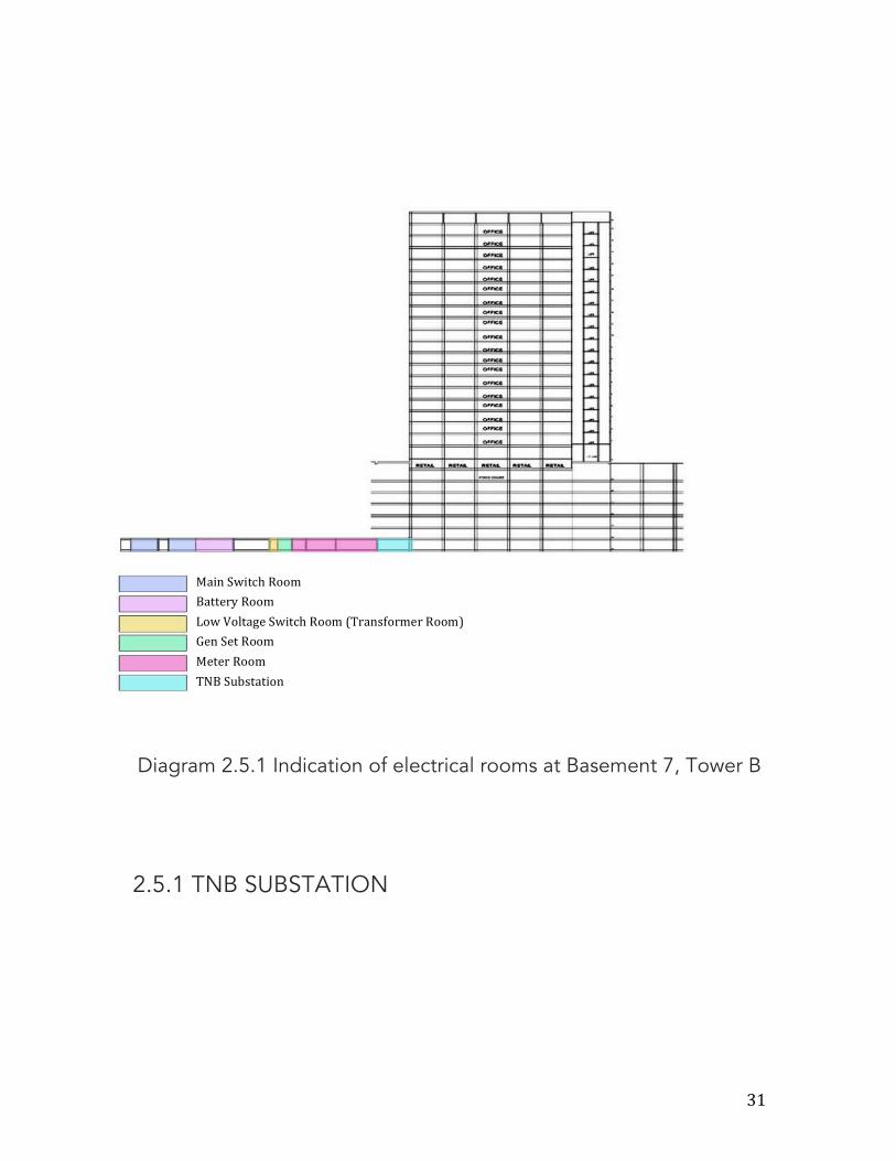
31
Diagram 2.5.1 Indication of electrical rooms at Basement 7, Tower B
2.5.1 TNB SUBSTATION
Main Switch Room Battery Room Low Voltage Switch Room (Transformer Room) Gen Set Room Meter Room TNB Substation

32
Figure 2.5.2 TNB Substation at PJ Trade Centre
Diagram 2.5.3 Location of TNB Substation on level B7
The substation at PJ Trade Centre is located at Basement 7.
The substation is an assemble of electrical components that are
connected in a definite sequnce in which a circuit can be switched

33
off maually or automatically. The substtaion receives electrical power
from generating station via incoming transmission lines and delivers
electrical power via the outgoing transmission lines.
There are four types of substations:
1. Transmission Substation
2. Distribution Substation
3. Collector Substation
4. Switching Substation
Every substation has the following parts and equipment:
1. Outdoor Swithyard
2. Main Office Building
3. Swithgear and control panel
4. Battery room and D.C. Contribution system
5. Mechanical, Electrical and other auxiliaries (firefighting system,
oil purification system, diesel generator set.

34
2.5.2 MAIN SWITCH ROOM
Figure 2.5.4 Main Switch Room at PJ Trade Centre

35
Diagram 2.5.5 Location of Main Switch Room on level B7
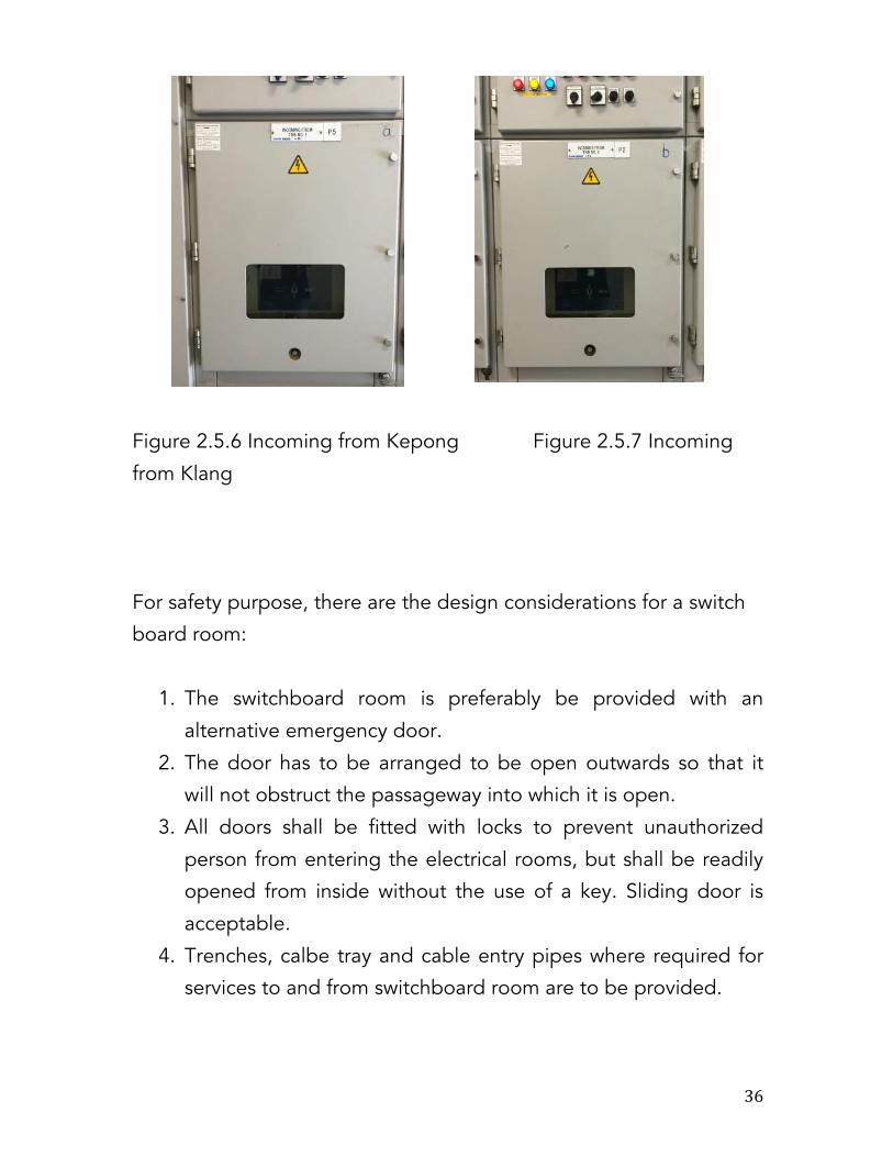
The main switch room is situated at Basement 7. Switchboard
is regarded as the main hud of the electrical power source
distributed to a building. Its main function is to receive electrical
power supply, control the power supply, distribute the power supply
and forfend the potency supply. Switchgear is one of the mechanism
installed at the switchboard used to open and break the circuit
designed to operate automatically or manually depending on the
required purposes. For PJ trade Centre, the power supply comes
from two sources which are from Kepong and Klang. The bus
coupler is the device which is used to couple one bus to the other
without any interruption in power supply and without creating
hazardous arcs. The bus coupler is located in between these two
incoming switchboards.
36
Figure 2.5.6 Incoming from Kepong Figure 2.5.7 Incoming
from Klang
For safety purpose, there are the design considerations for a switch
board room:
1. The switchboard room is preferably be provided with an
alternative emergency door.
2. The door has to be arranged to be open outwards so that it
will not obstruct the passageway into which it is open.
3. All doors shall be fitted with locks to prevent unauthorized
person from entering the electrical rooms, but shall be readily
opened from inside without the use of a key. Sliding door is
acceptable.
4. Trenches, calbe tray and cable entry pipes where required for
services to and from switchboard room are to be provided.

37
2.5.3 LOW VOLTAGE HIGH ROOM
Figure 2.5.8 One of the low voltage room at PJ Trade Centre
Diagram 2.5.9 The location of the main LVswitch room and LV room
for Tower B

38
Low voltage (LV) switch rooms are common across all
industries and one of the more common spatial requirements which
is needed to be designed in a project. Main low voltage (LV) switch
room will typically contain free standing switchboards and Motor
Control Centres (MCC), along with auciliary equipment required for
the room to function.
National and international standards define the manner in
which electric circuits of LV installations must be realized, and the
capabilities and circumscriptions of the sundry switching contrivances
which are collectively referred to as switchgear. Electrical protection
at low voltage is (apart from fuses) mundanely incorporated in circuit-
breakers, in the form of thermal-magnetic contrivances and/or
residual-current operated tripping contrivances.
The main functions of switchgear are:
• Electrical protection
• Electrical isolation of sections of an installation
• Local or remote switching
In integration to those functions shown in above, the other functions
of LV is namely:
• Over-voltage protection
• Under-voltage protection

39
Diagram 2.5.10 Low Voltage Switchgears
Design considerations for a Low Voltage Switchroom:
1. Two accesses for personnel; one is the normal access and one
for emergency.
2. Access for equipments; installation, operation and
maintenance.

40
3. Regulatory compliance and approvals.
4. Cable containment and entries.
5. Earthing and grounding.
6. Water sealing (if below ground).
7. Air conditioning, lighting and small power.
8. Fire detection, alarm and suppression.
Figure 2.5.11 Fire suppression system in LV switchroom

41
Fire Fighting Systems help protect critical high-value assets from the
threat of fire and minimize downtime and cleanup costs, while
addressing environmental considerations
Switchboards In a low voltage switchroom, actual switchboard dimensions should
be used. The typical switchboard dimensions are:
Height: 2.2 m (2000 mm for the switchboard and a 200 mm plinth)
Width: 600 mm to 1050 mm depending on construction
Depth : 600 mm
Weight : 200 to 400 kg per panel
Room Dimensions and Clearances Clearances around switchboard should comply to local regulations.
The room dimensions and switchboard clearances are as below:
1. Switchboard rear clearance
• 0 cm for front entry switchboard
• 75 cm for rear entry switchboard
2. Switchboard side clearance
• 100 cm for all switchboard
3. Switchboard front clearance
• 70 cm to 150cm for all switchboards
4. Vertical clearance avove switchboard
• 400 mm (may require additional)

42
Diagram 2.5.12 The diagram above shows the typical switchboard
arrangement in an LV room and its dimensions.
2.3.4 GEN SET ROOM
Figure 2.5.13 The Gen Set Room at PJ Trade Centre

43
Diagram 2.5.14 Location of Gen Set room on Level B7
Although the space requirements for standby and
emergency power systems do not rank at the top of an architect’s
design list, service personnel find themselves in tight quarters when
these power systems are jammed into areas that meet only minimum
safety requirements and don’t take service- ability into account.
Building service equipment must have an advocate early in the
design process. It is far easier and less expensive to plan for
adequate space in the design phase than to compromise on unit size
and retrofit equipment to fit in cramped areas.
A genset room is a specific case of engine-generator in
which a diesel engine combines with an electric generator to
generate electricity. As stated on the section, the genset room is
located further away from the other rooms due to the noises and the
danger it may produce if not properly handled. This generator are
used without the connection to the power grid and is used as an
emergency power supply if the grid fails.

44
Service Considerations for a Gen Set Installation:
• The Generator Room
• Gen Set Support Systems
• Controls
• Sound Attenuation
The basic design considerations for a gen set room are as below:
1. 3 to 4 feet (1m to 1.3m) of aisle space between live
electrical components of 600 volts or less, depending on
whether live components are on one or both sides of the
aisle.
2. Installations over 600 volts require even wider aisle
space, from 3 feet (1,) to as much as 12 feet (4m) for
voltages above 75kV.
3. Service rooms with 1,200 amps or more require two exits
in case of fire or arcing.
4. Floor space between an engine and parallel wall space or
another gen set should not be less than the width of the
engine.
5. There should be enough space allocated to allow
convenient removal of cylinder heads, manifolds, exhaust
piping and any other equipment for service.
6. Batteries to start gen sets should be kept as near as
possible to the engine to avoid long energy robbing
cables.
7. The fuel tank should be located near gen sets to prevent
long fuel line runs which can tax fuel pumps. Access to

45
this equipment for service must also be considered in the
design phase.
8. Controls and switchgear are best housed in a separate
air-conditioned room next to the gen set with a window
into the engine room.
9. Switchgear that can’t be placed in a separate room
should be located to take advantage of incoming air to
cool the switchgear.
Figure 2.5.15 The diesel tank (fuel tank) which is located behind the
Gen Set at PJ Trade Centre.
2.5.5 METER ROOM

46
Figure 2.5.15 One of the meter at PJ Trade Centre
Multi tenanted commercial premises except shop lots shall be given
bulk supply. The meter shall be installed at the metering rrom. An
enclosed locked room specifically for the purpose of installing floor
mounted metering cubicle shall be provided. The minimum size of
the room shall be 2.0 m x 2.0 m x 2.5 m height.
Acceptable Meter Locations for Commercial and Industrial (in
general) are as below:
1. For single occupancy non-residential and industrial
buildings, meters and metering equipment shall be
installed: a. Outdoors and mounted on an exterior wall
with vehicle access, or b. Within a meter room inside the
building on the first floor and with access only by a door

47
opening to the outside of the building with vehicle
access.
2. For multiple occupancy buildings meters and metering
equipment shall be located per above Number 1a or 1b,
and shall be grouped in one readily accessible central
location, accessible to all occupants. Meter sockets must
be permanently and clearly identified.
3. Service stations - the meter location shall be located such
that it is a minimum of twenty (20) feet clear of any gas
pump and ten (10) feet clear of any gas storage tank fill
spout and/or vent.
The besic design considerations of a meter room are as below:
1. An enclosed locked room specifically for the purpose of
installing floor mounted metering cubicle shall be provided.
2. The minimum size of the room shall be 2.0 m x 2.0 m x 2.5 m
(height). Key to the metering room shall be supplied and kept
by TNB.
3. The location of the metering room shall be inside TNB's
substation / switching station for consumers taking supply up
to 33 kV.
4. For consumers taking supply above 33 kV, the location of the
metering room shall be at consumer’s premise.

48
Diagram 2.5.16 Location to install the metering cubicle inside the
metering room shall be as in the layout above.
2.6 CONCLUSION According to Uniform Building by Law (UBBL) complied by the PJ
Trade Centre, every element in electrical supply system are built
accordingly in the correct place and each of the electricity
component play their roles. In conclusion, we can conclude that the
electrical supply system at PJ Trade Centre follows the necessary
requisites set by the governments for operating the building in terms
of electricity, the voltage supplied is sufficient. Below is the summary

49
of the flow of electricity supply system taking place at PJ Trade
Centre.
Kepong Klang
TNB Room
Consumer Switch Room
Transformer
Main Switch Boards • Circuit Breaker
Gen Set Room
Subswitch Boards
Distribution Boards
Power Points

50
3.0 WATER SUPPLY SYSTEM
51
3.1 INTRODUCTION
This chapter is basically explains on how the basic and general study
upon water services available in the case study chosen which is PJ
TRADE CENTRE Block B. The information mentioned is associated
with the case study regarding how the water supply is available and
being distributed throughout the whole building of block B.
The water supply system case study will be covered also to include
the water services, water distribution system and also water supply
piping. It will also be analyzed to give better understanding
regarding the water services.
3.2 LITERATURE REVIEW
The water supply is essentially crucial to maintain the health of the
community, business, agriculturally and sustainability of the industry.
Without a sufficient water supply system, our present society basis
would not have evolved and our lives today wouldn’t be
recognizable and threatened by our own surroundings. With an
advanced technologies evolving, and knowing the amount of
pollutions are increasing, we depend on well-treated water to avoid
extortions. Knowing that the capacity of water consumed by our
community each week, enormous infrastructures were required to
maintain well-treated water.
In Malaysia itself there are numbers of private water firms that
together supplies to billions of patrons with billions litres of water.

52
Based on a research, SYABAS is one of the private firms that
currently contribute treated water to over a few million patrons in
Kuala Lumpur, Selangor and Putrajaya.
The water supplied is one of the most fundamental businesses in
SYABAS that would be related to other patrons, which it has been
treated and processed before the distribution actions taking its part.
Rain falls and river flows will be pumped to the water treatment
plant, hence raw water is treated by going through the process of
aeration, coagulation, flocculation, sedimentation, filtration,
disinfection and conditioning. The treated water that is already safe
and clean for drinking will then be forced to the balancing reservoirs
before being distributed to service reservoirs. From here, then water
is supplied to its patrons. Water supply systems must also meet
requirements for public, commercial, and industrial activities. In all
cases, the water must achieve both quality and quantity
requirements.
3.3 WATER SUPPLY BY LAW
“Water supply and services in Malaysia is under the concurrent
jurisdiction of the Federal Government and State Governments. In
order to increase the country’s water services quality particularly
protecting consumers’ rights, two legislative frameworks, namely the
National Water Service Industry (NSW) Act (2006) (Act 655) and the
National Water Services Commission (SPAN) Act (2006) (Act 65) were
introduced.
With a well-regulated water services in place, this will help to

53
promote efficiency and long-term sustainability of the water industry
to benefit the consumers, investors as well as the operators.
Consumers in Malaysia enjoy a 24-hour water supply and water is
reliable and safe in terms of quantity and quality. It is treated
according to international standards for drinking water set out by the
World Health Organization (WHO). All domestic, commercial and
industrial users are metered. Water tariff are vary from state to state.
“ by the Malaysian Investment Development Authority
3.4 CASE STUDY
In PJ Trade Centre, water is used as domestic purposes, for toilets
and for sprinkler system where it will project water to the fire when
there is a fire incident happening to the building.
PJ Trade Centre is also known with their rainfalls collection system.
There’s a sky garden located from tower B to tower C, this is where
the rainwater collection points play its role. From the sky garden, it
will flow to their irrigation tank located at basement level 1. It will
then proceed to their booster pump which it will pump the water to
the plaza. This water will be used for trees and to clean their garden.

54
3.4.1 WATER STORAGE
Water supply and sanitation in Malaysia is characterized by various
achievements, as well as some challenges. According to research,
due to the differences in climate, culture and economic wealth, water
demand varies significantly between countries. The demand for
water also varies over the 24-hour period.
Hence, storage capacity required for a particular building will be
determined from hours of supply, pressure in mains and fire storage
requirements.
In PJ Trade Centre, every each blocks has been given two storage
compartments; underground and overhead storage.
Overhead storage.
These compartments are located on the rooftop level 21 of every
Diagram: Section PJ Trade Centre.
Water tanks are located at basement level 7, basement level 1 and on the rooftop level 21.

55
block. This is where the main clean water will be distributed to every
floor of the block.
Underground storage.
From SYABAS water tank, water will be distributed to the
underground storage here on the basement down below level 7.
From this storage, water will then flows to PJ Trade Centre own
filtration tank, which also located at the same area.
To store water, water storage needed to be installed and there are a
few requirements needed to fulfill linking to installation and
protection of water storage tanks:
• Tanks needed to be located somewhere accessible for repairs,
maintenance, inspections and replacement.
• Tanks are to be installed on bases above ground level,
platforms where the tank is being located at is designed to bear the
weight of the tank when it is filled to maximum capacity, without
unnecessary alteration taking place.
• Metal tank must to be out of a membrane of non-corrosive
insulating material between the support and the underside of the
tank.
• Tanks must be supported in a certain method, so that no load
is transferred to any of the attached pipes.
• Insulation from heat and cold should also be specified.
• Tanks must be provided with a cover, designed to prevent the
entry of dust, roof water, surface water, groundwater, birds, animals,
insects or anything that could possibly pollute the water inside.
• Tanks storing potable water should not be located directly
beneath any sanitary plumbing or any other pipes conveying non-

56
potable water.
Water tanks placement.
Figure: Collection tank.
Figure: Water storage located on the rooftop level 21.
There are two main
water tanks located at
basement level 7 of PJ
Trade Centre for every
each block, which is the
Collection tank and
Filtration tank.
Collection tank is used
to store water from
SYABAS. From the
collection tank, water
will be pump to the
filtration tank for another
filtration process. The
water then will be pump
to their domestic tank
located at the rooftop.
level 21.

57
Figure: Filtration Tank.
3.4.2. WATER SUPPLY
Source of water supply for
PJ Trade Centre comes
directly from SYABAS,
which stands for “Syarikat
Bekalan Air Selangor Sdn.
Bhd.” It is a company
where it’s in charge of
water distribution in Selangor. Water
supply from SYABAS comes directly from the water main,
underground and then being distributed to the water bulk meter,
which is located near the car parking area.
3.4.3. PUMP SYSTEMS
The type of pump been selected are based upon numerous factors,
Figure: SYABAS Logo.

58
the size of the storage or pressure tank used, the daily flow needed
by the users, and the total operating pressure tank used, and the
total operating pressure against which the pump works. Cost,
maintenance, and reliability are also one of the factors, as in the
energy used by the pump.
Of all these factors, the two most serious selection factors are the
flow rate and the total pressure. The flow rate depends upon the
amount of fixtures to be served. The total pressure includes the static
head, suction lift, and friction loss plus the pressure head.
Pressurize pump.
Pressure water pump, though it works the same as regular electric
water pump, differ in the system application. By the use of a driver,
the electric motor or gasoline engine and the pumping mechanism
itself, it able to move water from one location to another. Normally it
is a single, open-faced impeller that moves the water inside a
contoured chamber. The chamber will then help in creating pressure
to the water on the outlet side of the pump, where in some styles of
water pumps, a little suction is created. The water will then sucked
into the inlet and then pushed throughout the outlet side with a
greater pressure when the impeller were arrange accordingly to the
right direction.
This method is applied during the process of pumping clean filtered
water from the filtration tank to their water tank up to the rooftop,
where their water tank located.
Booster pump.

59
A water pressure booster pump will increase the water pressure
coming out of the faucets and appliances in a building. PJ Trade
Centre have one of their own booster pump which channels the
water down to 4 first levels below level 21, which are, 20, 19, 18, 17.
This happened because there is not much of pressure going on
these levels.
Pressure-reducing valve.
In between of the water distribution at every level of PJ Trade
Centre, which flows by gravity energy, they have installed the
pressure-reducing pump. This is to lower down the pressure of water
flow.
The pressure tank not only acts as a small tank for the accrued water,
but also to help maintaining a pressure on the system. The tank is
covered with rubber bladder and it can be occupied with air from an
air compressor. Generally the air bladder is occupied to hold nearly
30 to 40 pounds of air pressure. The amount of air helps in
maintaining the water system. The rubber bladder will also prevent
hard cycling of water pump. Hard cycling occurs when the pump
continuously turns on then off in repeated manner. It will then burn
the pump motor and also break the pipefittings by the acceleration
of the water in a closed spaced.
Hence, this pressure-reducing valve is used to prevent the break of
pipefittings.

60
3.4.4 COLD WATER SYSTEM
1.4.5 WATER METER
Water meter are supplied at the discretion of the local water
authorities. Most new buildings are mandatory to have them. There
are two common approaches to flow measurement, displacement
and velocity. The common displacement designs comprise
oscillating piston and nutating disc meter. Velocity – based on
The water supply comes from the main supply tank located at the basement level 7 floor of the building and pump up to the main water domestic tanks for storage purposes. From the domestic tanks, located on the rooftop, the cold water will be distributed throughout the basement via domestic water pumps and booster pump. The building has 21 floors to distribute water to, and since the domestic pump is located above all the floors, booster pump is used to pump the first four levels from 21 till 17. Then the gravity is used to distribute the water to the lower floor levels.
Diagram: Gravitational System

61
designs comprise single and multi-jet meters and turbine meters.
This method has been applied in most of the high-rise building.
Figure: Water meter
Diagram: Of how water meter
functioned.

62
Diagram : Water meter components.
3.4.6 MAINTENANCE
Maintenance is very crucial to prevent water supply from any
circumstances of failures. By far, PJ Trade Centre is in a good hand,
where nothing serious ever happened to the water supply. Usually
due to a common problem, leakage, data center will have the toilets
to stand-alone for almost all the floors. Maintenance in Security
Commission Building must be done once every month.
3.5 ANALYSIS
Cold water supply system used in PJ Trade Centre is main water
supply where they use water tanks to store in water from the water
main and delivers the water throughout the entire building according
to blocks. The profit of using this system is that the water tanks

63
supplies the water, in case of a shortage from the water main.
Moreover, the water tanks used are sufficient enough in this building
to offer water supply and as preparation when there is a shortage. In
this system, water pumps are needed to push up the pressure as the
water supply from the main is low. In PJ Trade Centre, domestic
water tank is placed on top of the roof which, had save up a lot of
cost on installing water pumper as the water is distributed by using
the gravitational force and booster pump. Besides, the installation of
water tank is a success, which they had fulfill the requirements
needed of the Uniform Building By-Law.

64
4.0 FIRE PROTECTION
SYSTEM

65
4.1 LITERATURE REVIEW
In Malaysia, the requirements of a building to have fire protection
systems are being installed into the design and the contraction of
the building. This fire protection is being used as to ensure that the
building is fully equipped and capable for the fire to be controlled
and extinguished. There are two components of fire protecting
system that called as Active Fire Protection System (AFPS) and
Passive Fire Protection System (PEPS). These two components are
being divided into its own individual sub-components with its own
different characteristic.
In the middle stage of designing a building, it is crucial for the
designer or architect to study the suitable types of fire protection
systems to be applied into the building. This should be depending
on the types of fire that could be happen in the building. These
followings are the types of fire group:-

66
Class A, considered as an ordinary combustible such as wood,
paper, cloth and plastics that commonly occur in typical commercial
and residential areas. For class B and Class K, the fire occur can
spread rapidly without any proper security and can easily revive after
the fire is extinguish. In some cases, there are fire cause by a spark
and that makes it in Class C where things like power surge or short
circuit and typical occur in areas that cannot be reach and see. Last
but not least it is the Class D, those fire are more unique as
compared to the other classes, it requires a special dry powder
agents as to contain.
The objective of five safety are listed in order of their usual
importance which is:-
67
1. Protection of life.
2. Protection of building.
3. Protection of contents.
4. Continuity of operation.
4.2 ACTIVE FIRE PROTECTION SYSTEM
4.2.1 FIRE DETECTION Fire detection is designed to detect an occurrence, alert the control
panel and notify the occupants to take action. The designs of fire
detection are specifically to provide the different of the building. It
can be work in two ways, which are automatically or manually.
Automatic activation can work with either smoke or heat detectors
while manual activation is by occupants of the building breaking the
glass unit or pulling the fire alarm pull station. The location of the fire
detection system must visible to alert the occupants through audio
as well as visual means. In the event, once the fire is detected, the
fire suppression and control system will be activated.
4.2.1.1 MANUALLY ACTUATED DEVICES Manually Activated Devices is a manual alarm activation that requires
human intervention. The person who is in charge of putting those
devices must ensure that it is easy accessible and visible for the users
of the building. There are few amounts of devices being use in PJ
Trade centre.

68
Figure 4.2.1: Break glass fire alarm.
Figure 4.2.2: Break glass and fire alarm.
(3)
4.2.1.2 AUTOMATICALLY ACTUATED DEVICES The function of this device is depending on the surrounding of the
building and has a negative and positive feedback to it. It uses to
detect heat as well as smoke. In the case of PJ Trade City, it only
uses smoke detector as for the entire building.

69
4.2.1.3 SMOKE DETECTORS A device that sense smoke, typically as an indicator when there is
fire. Signal from commercial and residential security devices issues a
signal to a fire alarm control panel as port of the fire alarm system,
while the smoke alarms, generally issue a local audible or even visual
alarm from the detector its own. It commonly can be worked in two
ways, which are optical detection methods or physical process
(Ionization). For optical detector, it uses the light sensor to detect
smoke particles that passes through it. For large areas such as
auditorium optical detector are used. It works by emitting rays and
reflecting it back to the device. When smoke pass though the
detector, a different reading will be detected and activating the
alarm, Figure 4.2.3. On the other hand, as for Ionization smoke
detector works by producing ionization in the air. It happens when
smoke passes though the detector and there is difference in
ionization in the air causes the trigger of the alarm shown in Figure 4.2.4.

70
Figure 4.2.3: Optical smoke detector principles. Figure 4.2.4: Ionization smoke
detector.
The smoke detector that is being used in PJ Trade Centre as shown
in Figure 1.2.5 below.
The smoke detector used as it can activate the alarm system as well
as the sprinkler system.

71
Figure 4.2.5: Smoke detector used in PJ Trade Center.
4.2.1.4 ALARM SYTEMS
In any building, easy understanding of the alarm system should
include visual and audio as to inform the building occupants when it
comes to the event. In other to achieve good alarm systems, the
combination of it should be the emergency lights, guide lights, alarm
bell as well as the emergency voice message communication system
as to guide the occupants in any circumstances. This kind of system
is normally being used in large-scale buildings such as malls also
high-rised building such as condominiums and apartments. It is by
far the most efficient and effective way as to alert the building
occupants during the event.

72
In PJ Trade Centre, it uses Emergency Voice Communication System
(EVCS). Messages are pre-recorded and will be use during the fire
outbreak as shown in Figure 4.2.5. It it also work as an access where
by it is used to communicate to people to the nearby the exits
during the fire outbreak. Emergency and exit signage found in some
part of the building as well, Figure 4.2.6.
Figure 4.2.5: Speaker that’s being used
for EVCS in PJ Trade Centre.
Figure 4.2.6: Emergency exit signage in PJ Trade Centre.
Not just that, emergency communication system is also provided in
PJ Trade Centre as shown in Figure 4.2.7. It is used to communicate
directly to reach the nearby fire station and control centre during the
fire outbreak.

73
Figure 4.2.7: Emergency fire communication system of PJ Trade Centre.
4.2.1.5 FIREMAN SWITCH Fireman switch is used to switch off the power supply of certain
power system of the building. It is usually being located at every
level of any building and it is being categorized into a few switches
with different types of electrical supply to be switched off and can
only be used by the “fireman”. Fireman switch located in PJ Trade
Centre, as shown in Figure4.2.8.
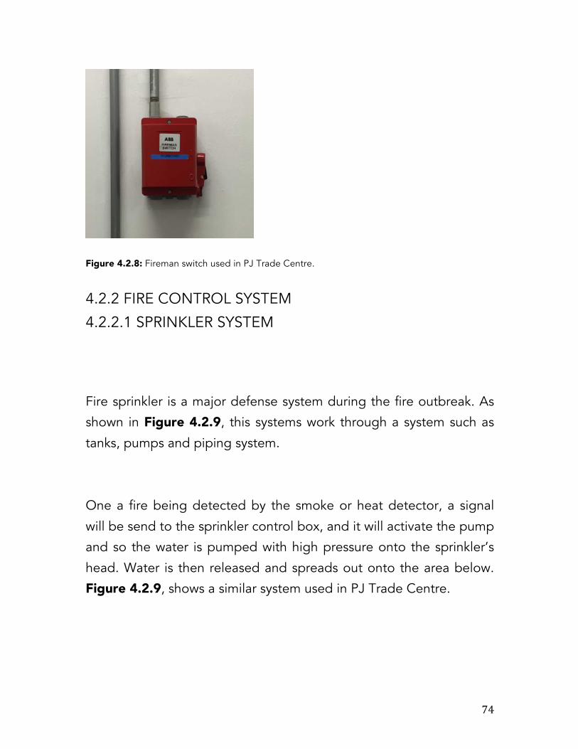
74
Figure 4.2.8: Fireman switch used in PJ Trade Centre.
4.2.2 FIRE CONTROL SYSTEM
4.2.2.1 SPRINKLER SYSTEM
Fire sprinkler is a major defense system during the fire outbreak. As
shown in Figure 4.2.9, this systems work through a system such as
tanks, pumps and piping system.
One a fire being detected by the smoke or heat detector, a signal
will be send to the sprinkler control box, and it will activate the pump
and so the water is pumped with high pressure onto the sprinkler’s
head. Water is then released and spreads out onto the area below.
Figure 4.2.9, shows a similar system used in PJ Trade Centre.

75
Figure 4.2.9: Typical sprinkler system that commercial buildings normally installed.
Figure 4.2.10: Layout of sprinkler piping and head in basement 7 of PJ Trade Centre.

76
TYPES OF SPRINKLER HEAD There are various types of sprinkler head used in PJ Trade Centre &
it function as to allow water to distribute in different ways for some
particular spaces.
Upright sprinkler heads project the water up into the space and can
normally found in the basement and mechanical area of PJ Trade
Centre as shown in Figure 4.2.11.
Figure 4.2.11: Upright sprinkler head.
Pendent Sprinkler, hanged down from the pipe towards the floor.
Normally can be found around the entire PJ Trade Centre, as shown
in Figure 4.2.12.

77
Figure 4.2.12: Pendent Sprinkler Head.
In selecting the area to install the sprinkler, there are certain
requirement that need to be followed depending on the usage of
the area and its hazard. The table below shows the types of
categories and the spacing requirements, in Figure 4.2.13.
Occupancy Hazard
Square Meter Per Head
Maximum Spacing Between Sprinklers
Light Hazard (Restaurants, Institutional,
Hospitals, Offices, Educational
and etc)
21m per head
4.6 meter
Ordinary Hazard (Machinery Shop, Post Offices,
Auto Parking, Manufacturing,
Shops and etc)
12m per head
4.0 meter

78
Extra Hazard (Chemical Spraying, Metal
extruding, Printing, Painting and
etc)
9m per head
3.7 meter
Figure 4.2.13: Basic requirements of installing the sprinkler head.
4.2.2.2 CO2 FIRE SUPPORTING SYSTEM In PJ Trade Centre, it uses CO2 suppression system in areas that
have a higher risk of fire outbreak. (Examples: Generator, electrical
room and etc). It releases the pressure of CO2 into an area through
the nozzles that have been placed somewhere. Here in Figure
4.2.14, shown the layout of CO2 system.
Figure 4.2.14: CO2 being placed in the high risks room of PJ Trade Centre.

79
Due to the fire, it’ll be reduce once CO2 is being released which
reduce the absence of oxygen. It can be work manually by breaking
the glass lever.
Figure 4.2.15: The CO2 storage.
4.2.2.3 FIRE EXTINGUISHER Fire extinguisher is required to be used by the building’s occupants
when the fire outbreak comes to the higher stages. It is being placed
mostly at the areas that are accessible and visible for the building
occupant’s to use during the emergency.
As for PJ Trade Centre, there are two different types of fire
extinguisher being used, which are dry powder system and the Co2
system. Those two fire extinguishing system has a different
properties and usage depending on the situation that is being faced

80
when it comes to the fire outbreak. Normally all of these fire
extinguisher are being placed in the hose reel rooms and the walls of
the interiors. In the case of PJ Trade Centre, it uses 9kg dry powder
and 3kg Co2 system.
Dry powder extinguisher Also known as ABC powder is catered for its capabilities and usage
of:
Type A : Wood, Paper and Textiles
Type B : Flammable Liquids
Type C : Flammable Gases
Electrical Contact
C02 extinguisher This type of extinguisher that used only to cater the fire from type B
and electrical conduct :
Type B : Flammable Liquids
Electrical Content
Figure1.2.16: Dry Powder Extinguisher. Figure 1.2.17: Co2 extinguisher.

81
4.2.2.4 HOSE REEL SYSTEM Fire hose reel works when high-pressure water is being push up
towards the hoses. It could be use by the building occupants or even
the fireman when the fire outbreak happens. This system can easily
be found in every level of the lift area also depending on certain
strategic point of area of PJ Trade Centre as shown in Figure 4.2.19.
Figure 4.2.18: The wet riser piping and
the hose reel piping are totally separated.
Figure 4.2.19: The hose reel system

82
This system can be found mostly around the high-risk area such as
electrical room and near the stairways. Fire extinguishers are
normally being placed at the same spot for this system. This system
requires designated piping system and storage tank all placed
together.
4.2.2.5 WET RISER SYSTEM This is where a system of rigid piping built in PJ Trade Centre. It
provides water towards the floors in the building without the help of
a hose. PJ Trade Centre applies wet riser system the fact that the
building is tall whereby dry riser system could not rely to the building
codes.
There are few stages of how this system runs whereby water is
pumped to the fire tank and series of pipes throughout the mall and

83
straight to the riser its own. This system has a hose, which needs to
be plugged as shown in Figure 4.2.20
Figure 4.2.20: Wet riser and hose. Figure 4.2.21: Wet rise distribution system (Fishlock, 2013)
4.2.2.6 FIRE HYDRANT SYSTEM Source of water provided onto the urban, suburban as well as rural
areas with Municipal water service to enable firefighters to tap into

84
the water supply as it helps to assist in terminating a fire. The way to
use it is where the user has to attach the Hose onto the fire hydrant
and opens up the valve on the hydrant as to provide a very powerful
water flow. Fire engine that has a water booster pump is commonly
used as to increase the water pressure. A big considerable has to be
taken on placing the fire hydrant so that the hose can easily being
used and easy accessible.
On top of that, fire hydrant are not design as to throttle the water
flow, but instead, it mean to be operated full-on or full-off. It should
be visible for the building occupants to see as shown in Figure
4.2.22. Figure 4.2.22: A typical fire hydrant
4.2.3 UBBL Bylaw Requirements UBBL By Laws - section 153 – Smoke Detector
1) All lifts lobbies shall be provided with smoke detectors.
2)
UBBL By Laws - section 154 – Emergency mode of operation in the event of mains power failure

85
1) On failure of mains power all lifts shall return in sequence
directly to the designated floor, commencing with fire lifts,
without answering ny car or landing calls and park with doors
open.
UBBL By Laws - section 225 – Fire Detection 1) Every building shall be provided with means of detecting and
extinguishing fire and with fire alarms together with illuminated
exit signs in accordance with the requirements as specified in
the Tenth Schedule to the By-laws.
2) In every office exceeding 92.9 square metres in area.
3) In each dwelling unit and hotel guest room where the fire
brigade system may combined with the public address system.
UBBL By Laws - section 237 – Fire Alarm 1) Fire alarms shall be provided in accordance with the Tenth
Schedule to the By-laws.
2) All Premises and buildings with gross floor area excluding car
park and storage areas exceeding 9290 square meters or
exceeding 30.5 meters in height shall be provided with a two
stage alarm system with evacuation (continuous signal) to be
given immediately in the effected section of the premises while
an alert (Intermittent signal) being given in adjoining section.
3) Provisions shall be made for general evacuation of the
premises by action of a master control.
UBBL By Laws - section 239 – Voice Communication System There shall be two separated approved continuously electrically
supervised voice communications system, one a fire brigade

86
communications system and the other public address system
between the central control station and the following areas:
1) Lift, lift lobbies, corridors, staircase and etc.
UBBL By Laws - section 240 – Electrical Isolation switch 1) Every floor or zone of any floor with a net area exceeding 929
square meters shall be provided with an electrical isolation
switch located within a staircase enclosure to permit the
disconnection of electrical power supply to the relevant floor or
zone served.
2) The switch shall be of a type similar to the fireman’s switch
specified.
UBBL By Laws - section 228 – Sprinkler valves 1) Sprinkler valves shall be located in a safe enclosed position on
the exterior wall and shall be readily to the fire authority.
2) All sprinkler system shall be connected to the nearest fire
station to provide immediate and automatic relay of the alarm
when activated.
UBBL By Laws - section 230 – Installation and testing of dry system
1) Dry rising systems shall be provided in every building in which
the topmost floor is more than 18.3 meters but less than 30.5
meters above fire appliance access level.
UBBL By Laws - section 231 – Installation and testing of wet system

87
1) 1) Wet rising systems shall be provided in every building in
which the topmost floor is more than 30.5 meters above fire
appliance access level.
OBSERVATIONAL ANALYSIS
By my own observation, PJ Trade Centre has met the stander
governed by the UBBL by laws. The systems provided are more than
comfort and clearly accessible. The voice communication can be
heard clearly throughout the whole building. Those hose reel system
are being placed to many strategic spots and it follow the by laws
which where some of those crucial room are protected by the fire
protection system.
PASSIVE FIRE SYSTEM Passive Fire System are use to contain fires or slow the spread
efficiently for users escaping from the fire but not stop it entirely. As
compared to Active Fire System, it uses mechanical features to
encounter the fire but actually it is all depends on its design, which
should be previously considered at the stage of designing the
structure.

88
4.3.1 COMPARTMENTATION Besides the Passive Fire Systems, other component of it is Compartmentation. It separates parts of the building into few
compartments as to prevent a fire spreading briskly.
4.3.1.2 FIRE CURTAIN Fiberglass material used as the Fire Curtain as to slow the massive
fire. Scientifically it has a lower resistant value as compared to the
fire shutter. The main purpose of fire curtain is to contain smoke
instead of fire and it only has a 1-hour fire rating. This system could
be found in any generator rooms of PJ Trade Centre.
Figure 4.3.1: Fire Curtain in ready position above the entrance.

89
Figure 4.3.2: A simplified diagram as how a fire curtain works.
4.3.2 OPENING PROTECTION
4.3.2.1 FIRE DOOR Any types of fire door must be equipped by fire ratings that will
reduce the spread of the fire and will protect occupants while
escaping from the burning building. Fire and smoke seals must also
be applied, including a mechanical door closer. The thickness of the
door wills effects how long would it lasts.
Figure 4.3.3: 2 hours fire door.

90
Figure 4.3.4: 1-hour fire door.
Figure 4.3.5: Fire door of PJ Trade Centre are clearly visible.
4.3.2.2 FIBRE REINFORCED PLASTIC DOOR This type of door as shown in Figure 4.3.6 is made out of Fibre
Reinforced Plastic (FRP) and only being used as for those high risk
area such as Switch Room and etc. Louvers that provide ventilation
can only last half an hour fire rating and also protected by the fire
curtain.

91
Figure 4.3.6: FRP door located at the external part of the building.
4.3.3 FIRE ESCAPE
Figure 4.3.7: Basement 7 floor plan showing the escape position.
4.3.3.1 VERTICAL ESCAPE An access build for the occupants to escape from any floors of the
building and fire fighters to enter the building when there is fire
outbreak and any other events. PJ Trade Centre uses as to prevent
smoke in the stairway.

92
Figure 4.3.8: Emergency Staircase of PJ Trade Centre.
4.3.3.2 HORIZONTAL ESCAPE Horizontal Escape is another escape that will route faster pathways
for the occupants to escape from the building when there is fire
outbreak or any emergency (Tavares, 2010). 4.3.4 Fire Lift A lift that is being built different from the other normal public lift as it
has different features inside of it. The lift is normally being used by
the fireman when it comes to the fire outbreak where all the other
public lifts are unable to be used. When the fire lift is on active
mood, all the other public lifts are being set to be off and will remain
at the Ground Floor level. This will cause only the fire lift will be
functional and the other lifts will remain as it is. In PJ Trade Centre,

93
the lift are located at the same area of the public lifts because it has
many different blocks all together which is more easy accessible.
Figure 4.3.9: The fire lift located next to a stairwell
and next to the public lifts.
Figure 4.3.10: Fire lift located next to the other public lifts.

94
4.3.5 LIGHTING AND SIGNAGE
4.3.5.1 EMERGENCY SIGN AND EXIT Emergency exit sign are provided at the entire are of PJ Trade
Centre as to ensure the user are clearly visible when it comes to the
evacuation. It is a green coloured board and a graphic of a man
running to a door. Normally can be found somewhere around the
pathways as it show the direction top the nearest exit.
Figure 4.3.11: Emergency Exit Sign with arrow.
4.3.5.2 EMERGENCY EXIT LIGHT A modern sign installation that is capable of illuminating the exit sign
in cases of any emergencies and made up of green fluorescent light
that is easy to be seen.
Figure 4.3.12: Shown “Keluar” means exit in Malay.
4.3.5.3 FIRE INDICATOR LIGHT

95
Fire Indicator light uses as to create a notification by using different
coloured lights, alerting the users in any emergency. It is mostly
located right above the entrance of any high risks rooms when a
person need to be notified of the room safety status before entering
the particular room.
A green and red bulb attached to a circuit box act as an indicator. It
is safe for the user to enter the room when the green light is up while
the red lights indicate that it is dangerous to use the room. For other
safety reason, the indicator is connected to the fire alarm to instantly
alert the authority of an on-going fire.
Figure 4.3.13: Fire indicator in PJ Trade Centre.
4.3.6 UBBL REQUIREMENT
UBBL By laws – section 110 – No obstruction in staircases 1) There shall be no obstruction in any staircase between the
topmost landing there and the exit discharge on the ground
floor.

96
2) There shall be no projection other than handrails in staircases,
in any corridor, passage of staircase at a level lower than 2
meters above the floor or above any stair.
UBBL By laws – section 137 – Floor in building exceeding 30 meters in height to be constructed as a compartment floor
1) In any building, which exceeds 30 meter in height, any floor,
which is more than 9 meters above ground level floor level
which separates one level from another level, other than a
floor, which either within a maisonette or a mezzanine floor
shall be constructed as a compartment floor.
UBBL By laws – section 147 – Construction of separating wall 1) Any separating wall, other than a wall separating buildings not
divided into compartments within the limits of size shall be
constructed wholly of non-combustible materials, excluding
any surface finish to a wall.
UBBL By laws – section 110 – Special requirements as to compartment walls and compartment floor
1) No opening shall be made in any compartment wall or
compartment floor with the exception of any one or more of
the following:
a. An opening fitted with a door which complies with the
requirements of by-law 162 and has FRP which is not less
than:-
i. In the case of a wall separating a flat or maisonette
from any space in common use giving access to that
flat or maisonette, half hour; or

97
ii. In any other case, the FRP required by the provisions
of these By-laws in respect of the wall or floor.
UBBL By laws – section 164 – Door closers for fire doors 1) All fire shall be fitted with automatic door closers of the
hydraulically spring operated type in the proper sequence.
2) Double door with rabbeted meeting stiles shall be provided
with co-ordinating device to ensure that leafs close in the
proper sequence.
3) Fire doors may be held open provided the hold open device
incorporates a heat actuated device to release the door. Heact
actuated devices shall not be permitted on fire doors
protecting openings to protected corridors or protected
staircases.
UBBL By laws – section 110 – Exits to accessible at all time 1) Except as permitted by by-law 167 not less than two separate
exits shall be provided from each storey together with such
additional exits as may be necessary.
2) The exits shall be so sited and the exit access shall be so
arranged that the exits are withing the limits of travel distance
as specified in the Seventh Schedule to these By-laws are
readily accessible at all times.
UBBL By laws – section 168 – Staircases
1) Except as provided for in by-law 194 every upper floor shall
have means of egress via at least two separate staircases.
2) Staircases shall be of such that in the event of any one staircase
not being available for escape purposes the remaining

98
staircases shall accommodate the highest occupancy load of
any one floor discharging into it calculated in accordance with
provisions in the Seventh Schedule to these By-laws.
3) The required width of a staircase shall be the clear width
between walls but handrails may be permitted to encroach on
this width to a maximum of 75 millimeters.
4) The required width of a staircase shall be maintained
throughout its length including at landings.
5) Doors giving access to staircases shall be so positioned that
their swing halls at no point encroach on the required width of
the staircase or landing.
UBBL By laws – section 171 – Horizontal Exits 1) Where appropriate, horizontal exits may be provided in lieu of
other exits.
2) Where horizontal exits are provided protected staircases and
final exits need only be of a width to accommodate the
occupancy load of the larger compartment or building
discharging into it so long as the total number of exits widths
provided is not reduced to less than half that would otherwise
be required for the whole building.
UBBL By laws – section 172– Emergency Exit Signs 1) Story exits and access to such exits shall be marked by readily
visible signs and shall not be obscured by any decorations,
furnishings or other equipment.
UBBL By laws – section 198 – Ventilation of staircase enclosure

99
2) All staircase enclosures shall be ventilated at each floor or
landing level by either permanent openings or operable
windows to the open air having a free area of not less than 1
square meter per floor.
UBBL By laws – section 110 – Pressurised system for staircase 1) All staircases serving buildings of more than 45.74 meters in
height where there are no adequate ventilation as required
shall be provided with a basic system of pressurization:
a. Where the air capacity of the fan shall be sufficient to
maintain an airflow of not less than 60 meters per minute
through the doors which are deemed to be open.
UBBL By laws – section 217 – Fire resistance of structural member
1) Any structural member or overloading wall shall have fire
resistance of not less than the minimum period required by
there by-laws for any element which it carries.
UBBL By laws – section 222 – Fire resistance for walls 1) Any structure, other than an external wall, enclosing a
protected shaft shall, if each side of the wall is separately
exposed to the test by fire, having fire resistance for not less
than minimum period required by this part.
2) Any compartment wall or separating wall shall, if each side of
the wall is separately exposed to the test by fire, have fire
resistance for not less than the minimum period required by
this part.

100
UBBL By laws – section 243 – Fire lifts 1) In a building where the top occupied floor us over 18.5 meters
above the fire appliance access level fire lifts shall be provided.
2) A penthouse occupying not more than 50% of the area of the
floor immediately below shall be exempted from this
measurement.
3) The fire lifts shall be located within a separate protected shaft if
it opens into a separate lobby.
4) Fire lifts shall be provided at the rate of one lift in every group
of lifts which discharge into the same protected enclosure or
smoke lobby containing the rising main, provided that the fire
lifts are located not more than 61 metres travel distances from
the furthermost point of floor.
4.4 ANALYSIS
Based on my personal observation, PJ Trade Centre applies the
passive fire system as it follows the UBBL laws. Shows that any exits
have to be accessible in any consequences. Founded that there is no
fired rated wall being installed in this building. Because from the info
gave from the Service Management, they did not state that there it
fire rated wall used in this building. Nevertheless, PJ Trade Centre’s
are more than safe and convenient.

101
5.0 MECHANICAL
TRANSPORTAI-ON SYSTEMS
102
5.1 INTRODUCTION Mechanical transportation systems are vertical transport devices that efficiently move goods or people between floors, levels and decks of a structure. They are classified as elevators (lifts), escalators and travellators. PJ trade centre however, only employs the use of elevator systems throughout the building.
5.2 LITERATURE REVIEW
Elevators or lifts are transport devices that move vertically, they are considered a requirement in all buildings over three storeys. In accordance to Malaysia Uniform Building By-Laws 1984, clause 124;
Elevators shall be provided for non-residential buildings which exceed 4 storeys above/below main entrance.
Ø Necessary in buildings less than 4 storeys if senior or disabled access is enforced
Ø Minimum walking distance to elevator shall not exceed 45m.
Ø Elevators should be position centrally in a building to minimize horizontal travel distance.
Clause 153 in the UBBL also states that a smoke detector is to be provided at the elevator’s lobby which also needs to be broad enough to grant traffic access in two directions.
Generally elevators are powered by electric motors that either drive traction cables or counterweight systems such as a hoist, or they pump hydraulic fluid that raise a cylindrical piston like a jack.
Elevators are classified according to the following:
• Hoist mechanism
• Building height

103
• Building type
• Elevator Location
• Special Uses
Vertical mechanical transportation is an important consideration when designing a multi-storey or a high rise building. Sufficient vertical transportation must be accommodated to the particular function and demographic of users of a building. Selection of the type of transportation equipment such as passenger, service and freight elevators directly correlate to the scale of a building and its quality. Vertical transportations systems represent a major building expense more often than not reaching up to 10% of the construction cost hence require intensive consideration to ensure successful and required operational quality of the building.
Quality of elevator service is also an important factor in the choice of tenants.
Elevator performance depends on :
• Acceleration
• Retardation
• Car speed
• Speed of door operation
• Stability of speed and performance with variations of car load
The criteria for the comfort and convenience of elevator users are wide and varied, they include directional indication of location of lift lobby for easy recognition, call buttons at landings and in the car with clear definitions of directions as well being at appropriate levels for every considered user demographic. Audible facilities and call lights/indicators are also an important part of elevator design, and
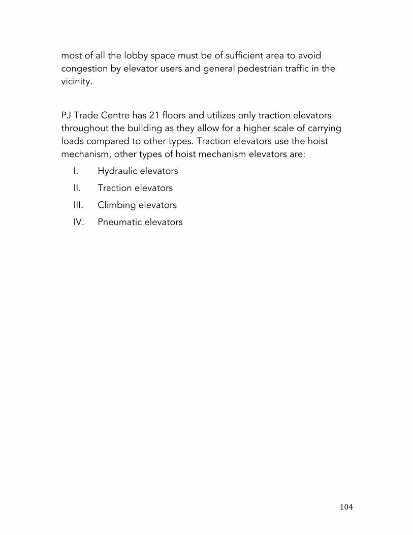
104
most of all the lobby space must be of sufficient area to avoid congestion by elevator users and general pedestrian traffic in the vicinity.
PJ Trade Centre has 21 floors and utilizes only traction elevators throughout the building as they allow for a higher scale of carrying loads compared to other types. Traction elevators use the hoist mechanism, other types of hoist mechanism elevators are:
I. Hydraulic elevators
II. Traction elevators
III. Climbing elevators
IV. Pneumatic elevators

105
5.3 CASE STUDY
PJ Trade Centre is a high volume building with elevators serving 21 storeys, speed and efficiency applies to this case with utmost importance. Electric traction elevators are employed because of its higher load carrying capacity due to the height of the building and in more specific terms, PJ Trade Centre uses geared traction elevators
because of its efficient and speedy properties.
5.3.1Principal Components
§ Electric Traction Passenger Lift
• The principle parts of a traction
elevator installation are the car, cables, elevator machine, control equipment, counterweights, hoistway, rails, penthouse and pit.
Figure 1 Components of Geared Traction Elevator

106
5.3.2 Car
The car is made of fire-resistant material and is supported on a structural frame to which the lifting cables are attached to a top member. Guide shoes on its side members guide the car during vertical travel in the shaft. The car is equipped with safety doors, operating control equipment, floor-level indicators, illumination, emergency exits and ventilation.
Figure 2 Section and plan view of Geared Traction Elevator Components.
Figure 3 Diagram of a typical lift motor room.

107
5.3.3 Cables
Lifting cables or ropes consist of groups of steel wires uniquely designed to withstand and support the weight of the car and its accompanying live load. They are attached to the crosshead ( top beam of elevator). Four to eight cables, depending on car speed and capacity are placed in parallel positions. Primarily, multiples of ropes are used to surge the traction area on the drive sheaves but they also additionally surge the elevator safety factor as each rope generally has the capability to support the entire load. The minimum safety factor varies from 7.6 to 12.0 for passenger lifts while they range from 6.6 to 11.0 for freight lifts.
Figure 2 Operating control system in PJ Trade Centre's elevator car.

108
5.3.4 Geared Traction Elevator
• Geared traction machines have a worm and gear interposed between the driving motor and the hoisting sheave. This allows the driving motor to be a smaller, cheaper and high-speed unit rather than the large low-speed unit required by a gearless installation
• Used for car speeds up to 2.3m/s. • With appropriate drive and
control system, a geared traction machine can give almost the same high-quality, accurate, smooth ride as a gearless installation.
5.3.5 Counterweight
Counter weight is made of cut steel plates stacked in a frame attached to opposite ends of the cables which are fastened to the car. It is guided vertically in the shaft by two guide rails typically set into the back wall of the shaft. Its weight equals that of the empty car plus 40% of the rated live load.
Figure 3 Diagram of a Geared Traction Elevator motor.
Figure 4 The Geared Traction Motor in PJ Trade Centre's lift motor room.

109
o It serves several purposes: to provide adequate traction at the sheave for car
lifting, to reduce the size of the traction machine, and to reduce power demand and
energy cost.
o Higher initial cost due to strengthen the overhead machine room floor, which
must carry the additional structural load of the counter weight.
5.3.6 Shaft
The shaft or hoistway is a vertical passageway for the car and counterweights. The walls on either side are equipped with the car guide rails and certain mechanical and electrical auxiliaries of the control apparatus. The bottom of the shaft is known as the pit and it contains the car and counterweight buffer. The top is basically a structural platform which supports the elevator machines. The elevator machine room normally occupies one or two levels and is usually placed directly above the shaft. It is where the traction machine and solid-state controls that supplies energy to the elevator machine and control equipment are placed and is designed for quiet, vibration-free operation. 5.4 SAFETY DEVICES The main brake of an elevator is mounted directly on the shaft. The lift is firstly slowed by dynamic braking of the motor after which the brake then operates to clamp the brake drum, thus holding the car still at a floor. A dual safety device is utilized to stop the car automatically in the event of over-speed:
• A centrifugal governor or an electronic speed control sensor cutes the power of the traction motor and sets the brake in case of limited over-speed.
• If over-speeding continues, governor activates two safety rail clams, which are mounted at the bottom of the car and one on either side.

110
Oil or spring buffers are usually placed in the pit, not for the purpose of stopping a falling car but to bring it to a somewhat cushioned stop if it over-travels the lower terminal.
5.5 ELEVATOR CONTROL SYSTEM Early elevators were operated by elevator operators using a motor controller via a projecting handle. This required a lot of skill from the elevator operators to accurately position the elevators. Nowadays, elevators use solid state microprocessor-based controls which are the industry standard. The modern elevator including PJ Trade Centre elevators has several sets of control systems to ensure safety and efficiency. 5.5.1 Elevator Car Controls An elevator car and all its part’s movements are controlled by two different interactive systems that provide a unified control system. This applies to PJ Trade Centre’s elevators too, the two systems are as follows:
• Drive Control System Ø Also known as motion control system, it determines car
acceleration rate, velocity, braking, leveling and regenerative braking as well as door motion. PJ Trade Centre uses a Variable Voltage DC Motor Control known as Ward Leonard System to control car acceleration and deceleration by restraining the speed of the traction elevator machine’s motor.
• Operating Control System Ø Determines the when and where of the physical motion
of a car and its doors. This system handles the operation of the car doors and integration with car buttons, lanterns, and passenger-operated devices into the overall and indicative system.

111
5.5.2 General Controls System A typical modern passenger elevator will incorporate the following general control systems:
• Overload sensor – prevents car from moving until excess load is removed. May trigger an alarm or audio prompt.
• Electric fans or air conditioning units – enhance ventilation and comfort.
• Control panel with various buttons: Ø Call buttons for floor selection Ø Door open and close buttons Ø Alarm button or switch
• Set of locked doors on each floor to prevent unintentional access into elevator shaft.
• “Nudge” function – closes doors at a reduced speed and sound a buzzer should the doors be kept deliberately open for too long.
• Emergency intercom for communication with the elevator controllers.
• Some elevators might have: Ø Elevator telephone Ø Hold button – for loading freight. Ø Call cancellation – destination floor may be deselected. Ø One or more additional sets of doors. Ø Security cameras.
• Other controls which are generally inaccessible to public are: Ø Fireman’s service, phase II key switch Ø Elevator enabling/disabling switch Ø Inspector’s switch

112
5.5.6 EXTERNAL CONTROL Elevators are typically controlled externally by a call box, which has directional buttons at each stop. This system is also known as or part of the Destination Control Systems, the elevator responds to calls according to the location/floor of the button pressed. In destination control systems, the operators can monitor and accordingly personalize and suit the response of the elevator car’s movements according to traffic flow or executive requests.
5.6 SPECIAL OPERATION SYSTEMS
• Anti-Crime Protection Ø The anti-crime protection(ACP) feature forces each car to
stop at a pre-defined landing and open its doors. This allows security personnel at the landing to visually inspect passengers.
• Inspection Service Ø This mode is designed to provide access to the hoistway
and car top for inspection and maintenance purposes by qualified elevator mechanics.
• Fire Service Ø Usually split into two modes: phase one and phase two.
o Phase one – activated by a corresponding smoke sensor or heat sensor located inside the building.
Figure 5 Elevator master external controls and surveillance in PJ Trade Centre.

113
Once activated, the elevator will go into nudging mode to inform everyone that it is leaving the floor. Once it has left, it will go to the fire-recall floor where it will stop with its doors open. It will stop responding to calls until the fire service key switch has been switched to bypass after the alarms are reset.
Ø Phase two – Activation can only be done via a key switch located inside the elevator on a centralized control panel. This particular mode was created for firefighter access for rescuing purposes. The switch has three positions; off, on and hold. The car will only respond to manual controls by the firefighters i.e. when the elevator reaches the desired floor its doors will not open unless prompted by the firefighter. This is to prevent fire and heat from entering the elevators and harming the firefighter should it be of close proximity to the elevator doors.
• Emergency Power Operation Ø Emergency power systems allow elevator use in the
event of an electrical blackout or power outage and prevent the trapping of people in elevations.
o PJ Trade Centre uses traction elevators and when power is lost in a traction elevator system, initially all elevator movements will be halted. Occupants of the elevators will be informed via indication light or audio announcement of the elevator’s return to lobby shortly. Upon the successful return of all cars the system will automatically select several cars for use in normal operations. Should the system detect that is it running low on emergency power, it will direct the running cars to the lobby or nearest floor, open the doors and shut down.
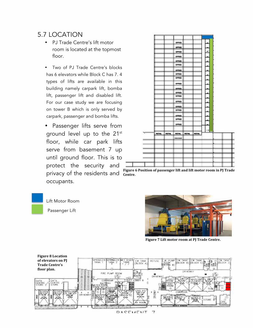
114
5.7 LOCATION • PJ Trade Centre’s lift motor
room is located at the topmost floor.
• Two of PJ Trade Centre’s blocks
has 6 elevators while Block C has 7. 4
types of lifts are available in this
building namely carpark lift, bomba
lift, passenger lift and disabled lift.
For our case study we are focusing
on tower B which is only served by
carpark, passenger and bomba lifts.
• Passenger lifts serve from ground level up to the 21st floor, while car park lifts serve from basement 7 up until ground floor. This is to protect the security and privacy of the residents and occupants.
Lift Motor Room
Passenger Lift 5.8 UBBL
Malaysia Uniform Building By-Laws, clause 151 states that;
Figure 6 Position of passenger lift and lift motor room in PJ Trade Centre.
Figure 7 Lift motor room at PJ Trade Centre.
Figure 8 Location of elevators on PJ Trade Centre's floor plan.

115
• Where openings to lift shafts are not connected to protected lobbies, such lift shafts shall be provided with vents of not less than 0.09sqm per lift located at the top of the shaft. Where the vent does not discharge directly to the open air the lift shafts shall be vented to the exterior through a duct of the required FRP as for the lift shafts.
Clause 152 states that: • Every opening in a lift shaft or lift entrance shall not open into a
protected lobby unless other suitable means of protection to the opening to the satisfaction of the local authority is provided. These requirements shall not apply to open type industrial and other special buildings as may be approved by the D.G.F.S.
• Landing doors shall have a FRP of not less than half the FRP of the hoist way structure with a minimum FRP of half hour.
• No glass shall be used for in landing doors except for vsion in which case any vision panel shall be glazed with wired safety glass, and shall not be more than 0.0161sqm and the total area of one or more vision panels in any landing door shall not be more than sqm.
• Each clear panel opening shall reject a sphere 150mm in diameter.
• Provision shall be made for the opening of all landing doors by means of an emergency key irrespective of the position of the lift car.
5.9 ANALYSIS The mechanical transportation system in PJ Trade Centre is applicable for the function of the building as a semi residential, commercial centre and office spaces. It is well designed to adapt and suit its occupant’s lifestyle, needs and safety and is projected accordingly to provide optimum service to the occupants.

116
6.0 MECHANICAL
VENTILATION & AIR-
CONDITIONING SYSTEM

117
6.1 LITERATURE REVIEW
HVAC is known as Heating, Ventilation, and Air-Conditioning System
that serves the main purpose of maintaining good indoor quality
with adequate ventilation to provide comfort and ventilation for the
users without harm the environments. Ventilation is simply defined as
the process of changing air in an enclosed space. A proportion of air
within the enclosed space should be continuously withdrawn and
replaced by fresh air.
MECHANICAL VENTILATION
Mechanical ventilation system is a system used to circulate
fresh air using ducts and fans rather than relying on airflow through
small holes or crack’s in a home’s wall, roof or windows. Moreover,
this mechanical ventilation system has been used widely since the
early of twentieth century, fan assisted movement of air has largely
superseded the unreliable natural system. These are the components
of the mechanical ventilation system:-
1. Fans:
Provide the motive power for air movement by imparting
static energy or pressure and kinetic energy or velocity. A fan’s
capacity for air movement depends on its characteristics such as
type, size, shape, number of blades and speed. Besides that, there
are four categories of fan suitable for air movement in ventilation
systems, which are cross-flow, propeller, axial flow and centrifugal.
2. Filters:

118
Filters are used to remove suspended particles, contaminants
and odours. The filters are usually installed at the inlet grille.
3. Ductworks:
The function of the ductwork is to channel outside air towards
the room or the air from the room towards the outside. It is usually
produced in circular, square or rectangular cross-sections in several
different materials.
4.Fire dampers
The fire damper also needed in case there is a fire occurrence,
which is to avoid the fire from spreading from one room to another.
It is usually placed at the compartment wall.
5. Diffusers
The diffusers range from simple perforated plated and grilles
to the more complex and efficient coned air distributors. The grille
and diffuser are located at the edge of the ductwork where the air
can easily released into the room.
AIR-CONDITIONING SYSTEM The definition of air-conditioning system is to control the
temperature, humidity, air cleanliness and air movement and heat
radiation with mechanical means, to achieve human thermal comfort.
The air temperature should be between 19 and 23 degree Celsius
and relative humidity within the 40-60% band. There are four types
of air-conditioning system:-

119
1. Room Air-Conditioner (Window Unit)
This Room Air Conditioner is the simplest form of air-
conditioning system and suitable only for a small room. It is usually
installed at window openings or wall. More over, it can be divided
into two compartments, which are the room side (evaporator) and
the outdoor side (condenser) that separated by an insulated
partition.
2. Split Unit Air-Conditioning System
Split unit air-conditioning system are one-to-one systems
consisting of one evaporator (fan coil) unit connected to an external
condensing unit. Both the indoor and outdoor units are connected
through copper tubing and electrical cabling. Besides, it is the most
popular type of air-condition nowadays as it is silent in operation,
has elegant looks, and no need to make a whole in the wall.
3. Packaged Unit Air-Conditioning System
The packaged air conditioners are used for the cooling capacities
that available in the fixed rated capacities of 3, 5, 7, 10 and 15 tons.
As the name implies, in the packaged air conditioners all the
important components of the air conditioners are enclose in a single
casing like window AC. Thus the compressor, cooling coil, air
handling unit and the air filter are all housed in a single casing and
assembled at the factory location. Depending on the type of the
cooling system used in these systems, the packaged air conditioners

120
are divided into two types, which are ones with water-cooled
condenser, and the ones with air-cooled condensers. http://www.brighthubengineering.com/hvac/906-central-air-conditioning-plants/ 4.Centralized or Plant Air-Conditioning System
Central air conditioning plants are used for application in big
buildings with commercial and offices uses where very high cooling
loads are required. It has the same limitation of the same air quality
being delivered throughout the building. The temperature of each
element can controlled with zoned thermostats.
6.2 PROLOGUE Currently, both Mechanical Ventilation and Air Conditioning system
are one of the alternatives to provide thus become one of the main
source to provide air circulation, air humidity, air quality and control
the air temperature inside of the building. PJ Trade Centre applied
the concept towards greeneries and uses more of natural ventilation
in order to minimize the usage of mechanical air conditioning system
in the building.
Generally in PJ Trade Centre, there are two types of air-conditioning
system they are used, which are Split Air-Conditioning System and
Centralized System. Tower B (Bata) uses the Split Air-Conditioning
System while Tower A and C used the Centralized System. It is

121
because Tower A and C are under one owner (Gamuda) unlike
Tower B which is under one owner. Therefore, there are different
opinions in approaching the usage of the Air-Conditioning System in
PJ Trade Centre. As we are doing the Tower B, we will focus more
on Split Air-Conditioning system in this report.
As for Mechanical Ventilation System, the building covered most of
the components that we learned in class. It is really important aspect
to insert mechanical ventilation especially in the basement room,
kitchen and toilet. The main purpose of mechanical ventilation is to
cool individual room, fireproof and filter small substances. Moreover,
it is to preserve oxygen content (maintained 21% of air volume) and
to remove carbon dioxide. Since we are do research on Tower B
only, some of the data necessarily need to gather in order to help us
in achieving building services foundation as well as approaching it in
greeneries way.
6.3 INTRODUCTIONS AND FUNCTION
Both Mechanical Ventilation and Air Conditioning system are
one of the main important source in providing the air circulation, air
quality, air humidity and also controlling the air temperature inside of
the building. Requirements on air conditioning and mechanical
ventilation systems if they are installed should be ‘reasonably
efficient’ based on the Building Regulations impose requirements.

122
In PJ Trade Centre Building, they use minimal of mechanical air
conditioning system for every building since their concept is mainly
towards greeneries and maximize on using natural ventilation.
6.4 COMPONENTS OF SYSTEM INVOLVED IN
MECHANICAL VENTILATION SYSTEM
6.4.1 Ducting System
Nowadays, it is a trend not to hide ducting systems, as it can
be quite aesthetically pleasing. In PJ Trade Centre, ducting systems
are designed to be exposed and visible. The function of ductwork is
to channel outside air towards the room or the air from the room
towards the outside. These are the components that can be found in
duct system which are diffusers, return air grilles, and fire dampers.
All ducting system in PJTC is usually insulated to reduce heat
loss and reduce installation cost. Besides that, the ductworks in PJTC
branches from AHU and to the allocated space especially basement
parking. Moreover, a loud noise could be heard when the operator
been switched on. The ducts that they use are rectangular shapes
and size range is 1m x 1.5m.
At the back of AHU (Air Handling Unit), there is a few Axial Fan to
exhaust the air from AHU via ducting. It consists of several aerofoil
cross sections blades mounted on a motor driven central shaft.

123
Axial fan in the ductwork where it can develop high-pressure and is
used for moving air through long sections of ductwork.
Ductwork at the basement

124
6.4.2 Extract Ventilation
In PJTC, the extract ventilation has been set up in the fire pump
room equipped with ductwork that attached to the extract fan in
order to accommodate the room with fresh air. It is also acts as to
prevent cross-flow of odours, smoke and noise through the extract
fan.
Extract ventilation in Fire Room
The Process of Extract Ventilation System in Fire Room
Source: Building Services, Technology and Design Book by Roger Greeno

125
Example of diagram below shows on how the smoke escapes
through the extract ventilation
Source: Building Services, Technology and Design Book by Roger Greeno

126
Location of centrifugal fan, fire damper and circular ductwork
6.4.3 Pressurization and Exhaust System for Fire Protection
A pressurization system is a system intended to prevent
smoke leaking passed closed doors into stairs by injecting clean air
into the stair enclosure such that the pressure in the stair is greater
than the adjacent fire compartment. Then, if the stair door is
opened, the system intended to maintain a flow of air through the
open doorway to oppose smoke flow and prevent contamination of
the stair enclosure. In PJTC, this could be seen that the system is
applied mostly in protected stairways area.

127
Pressurization consists of three components, which are Supply
Air (to transfer the air into specific spaces), Pressure Relief (to prevent
from exceed pressure) and Air Release (air and smoke are released
from the adjacent fire area). Due to all these components, it forms a
positive pressure difference to prevent smoke enter lobbies and
staircase area.
The supply air fan from exhaust louvers distance should be 5
m distance and 5 m distance to the wall. This is to ensure the
possibility of smoke shift into the supply airshaft. In PJTC they are
also install sets of motor fans purposely to suck air into the stairwell
that placed in the basement.
Fire damper at the emergency staircase area.

128
Ductwork to channel the smoke during fire event
Centrifugal Fan on rooftop
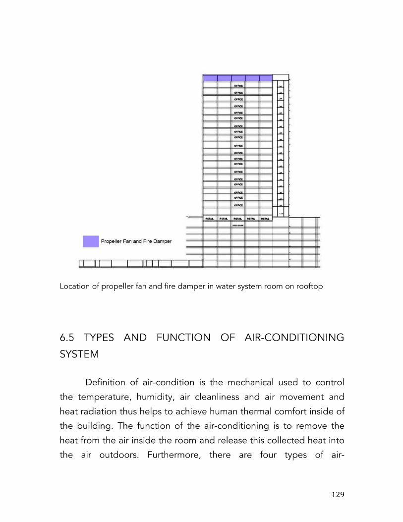
129
Location of propeller fan and fire damper in water system room on rooftop
6.5 TYPES AND FUNCTION OF AIR-CONDITIONING
SYSTEM Definition of air-condition is the mechanical used to control
the temperature, humidity, air cleanliness and air movement and
heat radiation thus helps to achieve human thermal comfort inside of
the building. The function of the air-conditioning is to remove the
heat from the air inside the room and release this collected heat into
the air outdoors. Furthermore, there are four types of air-

130
conditioning system which are room air conditioner (window unit),
split unit air conditioning system, packaged unit air-conditioning
system and centralized or plant air-conditioning system
In this report, we will focus more on air-conditioning in Tower
B which is the type of air-condition used is split unit air-conditioning
system. Meanwhile, for Tower A, Tower C and Tower D used
centralized air conditioning system. The reason of Tower B used split
unit air-conditioning system is because a few owners own the tower.
So they decided to install this split unit air-conditioning to be fair in
paying bills.
6.5.1 Split Unit Air-Conditioning System Split unit air-conditioner is the most popular type of air-condition
nowadays due to it silent in operation, elegant looks and no need to
make a whole in the wall. The meaning of split air-condition is the
condenser (outdoor unit) is separated from the indoor unit thus the
term ‘split’ is applied. The compressor (outdoor unit) is placed
outside of the room. Some models come with multiple indoor units
that will use one compressor, which is known as multi split air-
conditioning system.

131
Outdoor unit Indoor unit
Source: http://www.purennatural.com/products/ams120hr-12000btu-ductless-
split-single-zone/
132
There is no supply of fresh air to renew the existing indoor air
for ductless split unit system. It is function by recycle and recirculate
the existing indoor air and normally it is used for small room area.
These are the indoor unit types that we noticed they used in Tower B
6.6 COMPONENTS OF THE SPLIT UNIT AIR CONDITINING
SYSTEM A split air conditioner contains two separate components sections,
one outdoors and one indoor. The outdoor section is a compressor
that initiates the cooling process while the indoor component is an
evaporator and fan. The two sections are connected with a set of
electrical wires and tubing used to transport air between the two
sections. Split air-conditioners can be considered as one of the most
energy-efficient cooling solution because they are able to eliminate
the needs of the ducts. This is because transport air through duct will
cause the energy loss up to 30%. These are a few components of
split unit air-conditioning system, which are:-

133
The green area is showing the area that used split unit air-conditioning system

134
6.6.1 Indoor Unit
Ceiling mounted type
Wall mounted type

135
We have seen that the indoor unit is been placed at the location
where the air can be easily distributed evenly throughout the room.
The wall mounted indoor unit should be located not too close to the
roof or ceiling that is preferably about 2.4m from the floor.
6.6.2 Outdoor Unit
Meanwhile, for the outdoor unit, it is placed in the open space
preferably on the terrace so that air can flow freely over the
compressor and condenser. Besides, the surface on which the
outdoor unit is to be installed should be rigid enough to avoid its
vibration. There should not be any obstacles in front of the outdoor
unit that would block the passage of hot air to the open space.
Outdoor unit
The outdoor unit contains the important parts of the split AC like
compressor, condenser, and expansion valve.

136
6.6.3 Compressor
The compressor is most important part of the any air conditioner. It
compresses the refrigerant (low temperature) and increases its to
high pressure before sending it to the condenser by external power.
Source: http://www.slideshare.net/NurulAdha2/air-cond
6.6.4 Condenser
The condenser used in the outdoor unit of split air conditioners is the
coiled copper tubing with one or more rows depending on the size
of the air conditioning unit and the compressor. The high
temperature and high pressure refrigerant (low temperature) from
the compressor comes in the condenser where it has to give up the
heat. The tubing is made up of copper since it rate of conduction of
heat is high. The condenser is also covered with the aluminum fins so
that the heat from the refrigerant can be removed at faster rate.

137
Source: http://www.brighthubengineering.com/hvac/45044-parts-of-the-split-air-
condioners-outdoor-unit/#imgn_3
6.6.5 Evaporator
The evaporator helps to absorbs the heat taken from the
surrounding and replaced it with cooled air
6.6.6 Capillary tube
The capillary tube is a simple refrigerant liquid metering device that
regulates the flow of refrigerant from the incoming high-pressure
side (from the compressor or condenser) into the low-pressure side
(in the cooling coil)
6.6.7 Expansion valve
The expansion valve is usually copper capillary tubing with several
rounds of coils. In the split air conditioners of bigger capacities
thermostatic expansion valve is used which is operated electronically
automatically. The high pressure and medium temperature

138
refrigerant leaves the condenser and enters the expansion valve,
where its temperature and pressure drops suddenly.
6.7 OPERATION OF SYSTEM The split unit air conditioner pumps heat from outside and change it
to cooling when it goes inside through the refrigeration cycle. The
refrigerant will undergoes the phase changes, pressure changes and
temperature changes when the refrigeration cycle is occurred.
Source: http://www.central-air-conditioner-and-
refrigeration.com/basic-refrigeration-cycle.html
In the article entitled “How Does a Split Air Conditioner Work?’
explains about the process of the split air-conditioner. The process is
start with the compressor that is controlled via a thermostat inside.
As the thermostat detects warm air, it activates the compressor

139
outdoors. The compressor circulates a refrigerant gas, increasing the
pressure and temperature of the refrigerant as it compresses it
through a series of pipes. The refrigerant than moves to the
condenser for further processing.
In the condenser, a cooling system removes heat from the high-
pressure gas and the gas changes phase and becomes a liquid. This
chilled liquid is pushed through tubing indoors until it reaches the
evaporator system.
Inside the building, the evaporator fan collects warm air and passes
it through a chamber containing the chilled liquid refrigerant. The
fan system then serves to blow this now-cooled air back into the
room, lowering the overall temperature of the space. If the
thermostat still detects air that is warmer than desirable, the process
continues, and the refrigerant and any excess heat that remains in
the system are passed back outdoors to the compressor in order to
begin the cycle anew.
http://www.doityourself.com/stry/how-does-a-split-air-conditioner-
work#b

140
6.8 UBBL REQUIREMENTS AND REGULATION Under UBBL 1984 Section 41: Mechanical Ventilation and Air-
Conditioning
1) Where permanent mechanical ventilation or air-conditioning is
intended, the relevant building by-laws relating to natural
ventilation, natural lighting and heights of rooms may be
waived at the discretion of the local authority.
2) Any application for the waiver of the relevant by-laws shall only
be considered if in addition to the permanent air conditioning
system there is provided alternative approved means of
ventilating the air-conditioned enclosure, such that within half-
an-hour of the air-conditioning system failing, not less that the
stipulated volume of fresh air specified hereinafter shall be
introduced into the enclosure during the period when the air-
conditioning is not functioning.
3) The provisions of the Third Schedule to these By-laws shall
apply to buildings, which are mechanically ventilated or air-
conditioned.
4) Where permanent mechanical ventilation in respect of
lavatories, water closets bathrooms or corridors is provided for
and maintained in accordance with the requirements of the
Third schedule to these By-laws, the provisions of these By-
laws, relating to natural ventilation and natural lighting shall not
apply to such lavatories, water closets, bathrooms or corridors.

141
6.9 CONCLUSION In conclusion, mechanical ventilation and air-conditioning become
one of the important systems thus contribute in achieving thermal
comfort in the building. It is well designed to meet the client
requirement and also need to ensure the comforts for the users.
Nevertheless, the cooling and ventilation system in PJ Trade Centre
is well planned and suits with the Malaysia’s climate too.

142
7.0 SANITARY AND
SEWERAGE SYSTEMS

143
7.1 INTRODUCTION
This chapter will cover on the sewerage and sanitary system in
general and also the system that is used in the case study building,
PJ Trade Centre. The system on the case study will be focusing on
Tower B; how the drainage system works throughout the building to
the manhole.
The sewerage and sanitary system at PJ Trade Centre will be on the
study of the sanitary system components, drainage, irrigation and
filtration systems.
7.2 LITERATURE REVIEW
Sanitation systems are often forgotten components of a domestic
plumbing system, yet they are vital to ensure that we have a clean
and safe environment to live in. Generally, the most contact we have
with a sanitation system is pulling out a plug in a wash hand basin or
flushing a WC. Luckily, most systems are well designed and simple in
their application, therefore very little can go wrong, however,
occasionally problems can occur. Sewerage refers to the
infrastructure that conveys sewage. It encompasses components
such as receiving drains, manholes, pumping stations, storm
overflows, and screening chambers of the amalgamated sewer or
sanitary sewer. Sewerage ends at the ingress to a sewage treatment
plant or at the point of discharge into the environment.
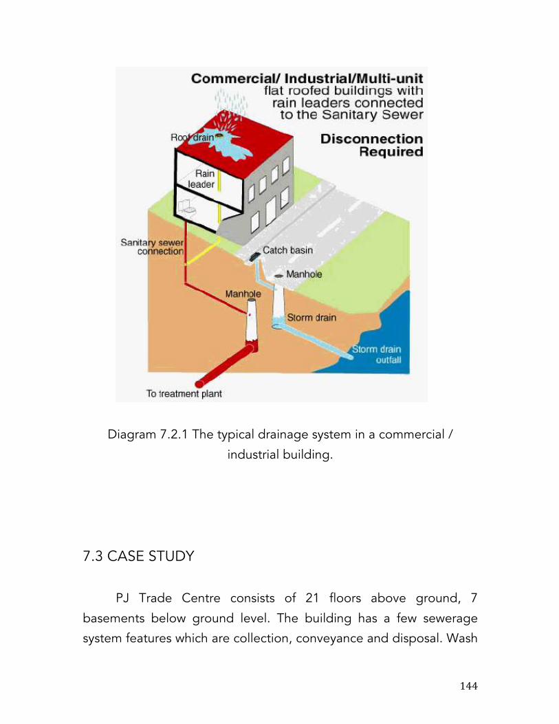
144
Diagram 7.2.1 The typical drainage system in a commercial /
industrial building.
7.3 CASE STUDY
PJ Trade Centre consists of 21 floors above ground, 7
basements below ground level. The building has a few sewerage
system features which are collection, conveyance and disposal. Wash
145
closets are located similarly on each floor to enable a direct stack
system that is both more cost and space efficient. Wastewater from
every level goes through several stages of collection and conveyance
through the one-pipe system which leads directly to the existing
sewers and nearest manhole.
7.3.1 SANITARY & SEWERAGE SYSTEM COMPONENTS
With a total combined number of 28 floors, PJ Trade Centre is
categorized as a high-rise building. These buildings are too tall to be
supplied throughout using just the normal pressure in the public
water mains and have particular needs such as pressure booster
systems in the design of their sanitary drainage and venting systems.
Pressure may also cause complications as the combined pressure
supplied by pressure booster systems may cause the total pressure
at the bottom to exceed the allowable safety level as regulated by
code and materials. PJ Trade Centre utilizes the one-pipe system
and pressure-reducing valves on each level to solve this problem.
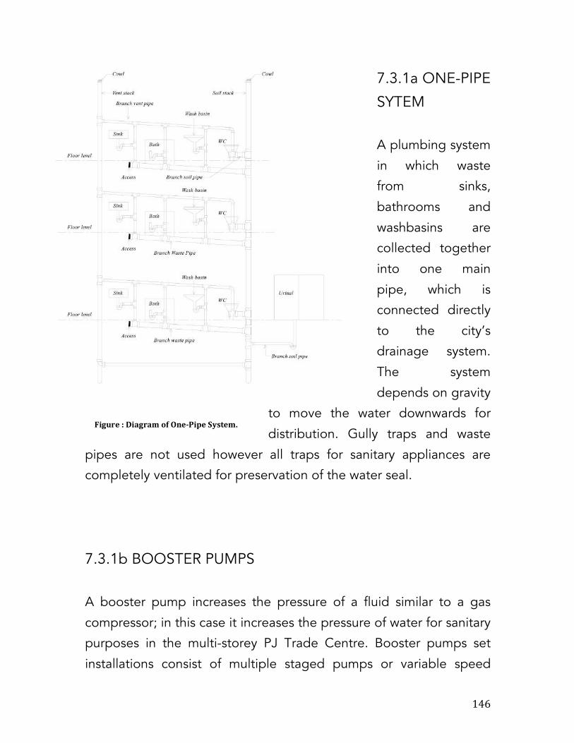
146
7.3.1a ONE-PIPE
SYTEM
A plumbing system
in which waste
from sinks,
bathrooms and
washbasins are
collected together
into one main
pipe, which is
connected directly
to the city’s
drainage system.
The system
depends on gravity
to move the water downwards for
distribution. Gully traps and waste
pipes are not used however all traps for sanitary appliances are
completely ventilated for preservation of the water seal.
7.3.1b BOOSTER PUMPS
A booster pump increases the pressure of a fluid similar to a gas
compressor; in this case it increases the pressure of water for sanitary
purposes in the multi-storey PJ Trade Centre. Booster pumps set
installations consist of multiple staged pumps or variable speed
Figure : Diagram of One-‐Pipe System.

147
pumps, which draw water directly from a gravity storage tank or the
public water main. Discharge pressure regulating valves to maintain
a constant water supply pressure.
7.3.1c DRAINAGE AND VENTING
Because PJ Trade Centre is a high-rise building and its sanitary
drainage system discharges to the public sewer using gravity, the
fixture drain traps are vented to prevent their water trap seal from
being compromised. With the motive force in the drainage process
being gravity, air is very critical to the drainage process because
without air the drainage would range from erratic to nonexistent. The
water seal is also important to maintain performance and prevent the
Figure : Booster pump in PJ Trade Centre's Water Tank & Pump Room.

148
equipment from being damaged. Surface water runoff are led into
channels that drain straight into the city’s sewers and manholes.
7.4 IRRIGATION SYSTEM
PJ Trade Centre also has an additional irrigation system that harvests
rainwater for reuse. As part of its green building system, the centre
utilizes a lot of greenery to reduce heat gain and incorporates
rainwater-harvesting systems on its rooftops, which collect water to
be stored for irrigation purposes. Rainwater is flows from the “sky
gardens” on the rooftop into the irrigation tank, which after filtration,
flows through two pumps that distribute the water to the plaza
where it will be used for watering plants. Any excess water will be
distributed back to the water supply tank for use in sanitation.
SKY GARDEN IIIRRIGATION TANK
PUMP
WATER SUPPLY PLAZA
PUMP
rainwater
Figure : Rainwater harvesting process.

149
7.5 FILTRATION SYSTEMS
7.5.1 GREASE TRAPS The food court and restaurants of PJ Trade Centre are served by a
separate drainage system than the sanitary system. Wastewaters
from the kitchens flow through a grease trap where they are filtered
before being released to the sewer for disposal. Grease traps are
also known as grease interceptor, grease recovery device or grease
converters, they are a plumbing device created to intercept most
greases and solids before they enter a wastewater disposal system.
Common wastewater contains small amounts of oil which form a
floating scum layer upon entering septic tanks or treatment facilities.
The scum layer is digested very slowly by microorganisms during the
anaerobic process until it is nonexistent. However, kitchens and
restaurants produce large amounts of oil during food production and
this can overwhelm a septic tank or treatment facility, possibly
causing contamination by inadvertently releasing untreated sewage
into the environment. The oil and grease can also potentially cause
blockages in drain pipes because of their tendency to solidify upon
combination with other solids. The grease trap used in PJ Trade
Centre is made from stainless steel and is located in a room roughly
about 3x5m in size on the level directly below the food-court and

150
restaurants. A contractor comes weekly to perform cleaning and
maintenance of the grease trap via the cleanout vents.
Figure Grease Trap in PJ Trade Centre.
Figure: Diagram of how a grease trap functions.

151
7.5.2 GRATINGS
A grating is any element that is a collection of essentially identical,
parallel, regularly spaced and elongated. Gratings are essentially a
filtration system taking the form of a perforated cover, they are fitted
over any outlet holes designed to trap and prevent any significantly
sized solids from entering the drainage system and potentially cause
blockages. They are also used to prevent users from accidentally
entering drainage holes and can also be used to filter air and are
often used in vents. PJ Trade Centre uses gratings extensively in
their filtration systems, toilets, compounds, etc. not just as a
necessary system and precaution but also as part of the building
design.

152
7.6 UBBL REQUIREMENTS
According to Malaysia Uniform Building By-Laws, section 123.
(1) Where ducts or enclosures are provided in any building to
accommodate pipes, cables or conduits, the dimensions of
such ducts or enclosure shall be –
a. Adequate for the accommodation of the pipes, cables
or conduits and the crossings of branches and mains
together with supports and fixing
Figure Above: A grating used to filter unwanted material from entering the irrigation tank. Right: decorative grating in building compound to allow surface water runoff.

153
b. Sufficiently large to permit access to cleaning eyes,
stopcocks and other controls to enable repairs,
extensions and modifications to be made to each or
all of the services accommodated.
(2) The access openings to ducts or enclosures shall be long
enough and suitably located to enable lengths of pipe to be
installed and removed.
Section 115 of the UBBL states that;
All roofs of buildings shall be constructed as to drain effectively to
suitable and sufficient channels, gutters, chutes or troughs which
shall be provided in accordance with the requirements of these By-
Laws for receiving and conveying all water which may fall on and
from the roof.
7.7 ANALYSIS
PJ Trade Centre is a great example of green building design and
manages to incorporate the successful integration of its services
systems and design quality for the most part. The sanitary and
sewerage system is of a very simple and efficient design that saves
cost and contributes to the environment. However, the building has
a mostly open design which means that the elements easily
penetrate into the extensive, sheltered outdoor areas, which include

154
corridors and lobbies. The design may become a liability as
improper drainage could easily occur in these areas, i.e. the brick
paved walkway of the plaza creates an uneven surface where water
collects between bricks and takes time to dry. Although drainage is
provided on its perimeters and in close proximity, not all-surface
runoff manages to drain into these outlets. Over time, this excess
water can potentially increase maintenance costs in the form of algae
prevention and furniture replacement (in lobbies), etc. They should
revise the drainage system to allow for the successful execution of
their design.

155
8.0 CONCLUSION

156
8.0 CONCLUSION.
Based on the study of services in PJ Trade Centre, the kinds of
services provided are already efficient and suitable for the building.
Completing this report was never an easy job. It must be accurate
and reliable. Therefore, the importance of teamwork is really needed
in making a good communication throughout the project.
Moreover, throughout this project we have learnt so much of how,
what and which systems suites well with a particular building.
Therefore, we have been exposed with the practiced of sustainable
design on PJ Trade Centre, which they have encountered into it.
In PJ Trade Centre, they really do focused on zoning-wise. Their building services were really well organized and most of it was at the basement level 7. The building and its services bonded with the landscape, which is aesthetically pleasing.
Last but not least, it was a really successful project and site visits in terms of better understanding on building services, teamwork and time management skills.

157
9.0 REFERENCES

158
9.0 REFERENCES Centre, P. (2015). PJ Trade Centre, Damansara Perdana |
Propwall. Propwall.my. Retrieved 11 May 2015, from http://www.propwall.my/damansara_perdana/pj_trade_centre
Pjtradecentre.com,. (2015). PJ Trade Centre - Crafted to Inspire | PJ Trade Centre. Retrieved 11 May 2015, from http://www.pjtradecentre.com
Pumpsystemsnola.com,. (2015). Pump Systems. Retrieved 11 May 2015, from http://www.pumpsystemsnola.com
Slideshare.net,. (2015). Cold Water Supply Distribution In Building. Retrieved 11 May 2015, from http://www.slideshare.net/mysteryech/cold-water-supply-distribution-in-building
Syabas.com.my,. (2015). Water Meter » Syarikat Bekalan Air Selangor Sdn. Bhd. (1-800-88-5252). Retrieved 11 May 2015, from http://www.syabas.com.my/consumer/water-meter
Tujuangemilang.com,. (2015). Our Projects: PJ Trade Centre | Tujuan Gemilang Sdn Bhd. Retrieved 11 May 2015, from http://www.tujuangemilang.com/pj-trade-centre.html
Wikipedia,. (2015). Water metering. Retrieved 11 May 2015, from http://en.wikipedia.org/wiki/Water_metering
Wikipedia,. (2015). Water supply and sanitation in Malaysia. Retrieved 11 May 2015, from http://en.wikipedia.org/wiki/Water_supply_and_sanitation_in_Malaysia
4.bp.blogspot.com,. (2015). Retrieved 11 May 2015, from http://4.bp.blogspot.com/-qP-vC4rF8BE/U-e-8CinReI/AAAAAAAAAXo/TJEpTZpMJZg/s1600/ABB17.jpeg

159
(2015). Retrieved 11 May 2015, from http://www.tnb.com.my/application/uploads/uploaded/ESAHv3.pdf
Electrical-installation.org,. (2015). The basic functions of LV switchgear - Electrical Installation Guide. Retrieved 11 May 2015, from http://www.electrical-installation.org/enwiki/The_basic_functions_of_LV_switchgear
Macallisterpowersystems.com,. (2015). Generator Set Rooms & Enclosures | MacAllister Power Systems. Retrieved 11 May 2015, from http://www.macallisterpowersystems.com/solutions/engineering-toolbox/generator-set-rooms-enclosures/
McFadyen, S. (2015). Low Voltage Switchroom Design Guide. Myelectrical.com. Retrieved 11 May 2015, from http://myelectrical.com/notes/entryid/175/low-voltage-switchroom-design-guide
Wbdg.org,. (2015). Electrical Engineering | Whole Building Design Guide. Retrieved 11 May 2015, from http://www.wbdg.org/design/dd_electricaleng.php
Wikipedia,. (2015). Electronic component. Retrieved 11 May 2015, from http://en.wikipedia.org/wiki/Electronic_component#Active_components
Wikipedia,. (2015). Semiconductor device. Retrieved 11 May 2015, from http://en.wikipedia.org/wiki/Semiconductor_device
(2015). Retrieved 11 May 2015, from http://www.who.int/water_sanitation_health/hygiene/plumbing14.pdf

160
(2015). Retrieved 11 May 2015, from http://ftp://law.resource.org/pub/bd/bnbc.2012/gov.bd.bnbc.2012.08.06.pdf
(2015). Retrieved 11 May 2015, from http://ftp://law.resource.org/pub/bd/bnbc.2012/gov.bd.bnbc.2012.08.06.pdf
Newcomb-boyd.com,. (2015). Retrieved 11 May 2015, from http://www.newcomb-boyd.com/wp-content/uploads/2014/09/DMC-High-RisePlumbingDesign.pdf?ec02a7
Wikipedia,. (2015). Booster pump. Retrieved 11 May 2015, from http://en.wikipedia.org/wiki/Booster_pump
Wikipedia,. (2015). Grease trap. Retrieved 11 May 2015, from http://en.wikipedia.org/wiki/Grease_trap
(2015). Retrieved 11 May 2015, from http://teacher.buet.ac.bd/zahurul/ME415/ME415_elevators.pdf
Electrical-knowhow.com,. (2015). Basic Elevator Components - Part One ~ Electrical Knowhow. Retrieved 11 May 2015, from http://www.electrical-knowhow.com/2012/04/basic-elevator-components-part-one.html
Otisworldwide.com,. (2015). Otis Worldwide | Elevators. Retrieved 11 May 2015, from http://www.otisworldwide.com/k2-elevators.html
Slideshare.net,. (2015). Transportation Systems In Buildings. Retrieved 11 May 2015, from http://www.slideshare.net/arkam_slideshare/transportation-systems-in-buildings
Wikipedia,. (2015). Elevator. Retrieved 11 May 2015, from http://en.wikipedia.org/wiki/Elevator#Controlling_elevators

161
Brighthub Engineering,. (2015). Parts of Split Air Condioners: Outdoor Unit. Retrieved 11 May 2015, from http://www.brighthubengineering.com/hvac/45044-parts-of-the-split-air-condioners-outdoor-unit/#imgn_3
Central-air-conditioner-and-refrigeration.com,. (2015). Basic Refrigeration Cycle. Retrieved 11 May 2015, from http://www.central-air-conditioner-and-refrigeration.com/basic-refrigeration-cycle.html
Doityourself.com,. (2015). How Does a Split Air Conditioner Work? | DoItYourself.com. Retrieved 11 May 2015, from http://www.doityourself.com/stry/how-does-a-split-air-conditioner-work#b
Inspectapedia.com,. (2015). Capillary Tubes: Air conditioning heat pump repair: Installation & Service Guide to Capillary Tubes as Refrigerant Metering Devices - refrigerator freezer repair guide. Retrieved 11 May 2015, from http://inspectapedia.com/aircond/Capillary_Tubes.htm
Pridiom Landmark 12, 0. (2015). Pridiom Landmark 12,000 BTU Single Zone Mini-Split Windowless Air Conditioner with Heat Pump. Pure Natural. Retrieved 11 May 2015, from http://www.purennatural.com/products/ams120hr-12000btu-ductless-split-single-zone/
S100.copyright.com,. (2015). Retrieved 11 May 2015, from https://s100.copyright.com/AppDispatchServlet?publisherName=ELS&contentID=S2214398X13000046&orderBeanReset=true
Sciencedirect.com,. (2015). Pressurization systems do not work & present a risk to life safety. Retrieved 11 May 2015, from http://www.sciencedirect.com/science/article/pii/S2214398X13000046

162
Slideshare.net,. (2015). Air cond. Retrieved 11 May 2015, from http://www.slideshare.net/NurulAdha2/air-cond
Greeno, R. (1997). Buidling Services, Technology and Design. Harlow: Longman Stein, B., & Reynolds, J. (1992). Mechanical and Electrical Equipment for Buildings (8th ed.). New York: J. Wiley & Sons. Santamouris, M. (2006). Building Ventilation The State of The Art. London: Earthscan. (High Rise Fire-fighting : Wet Risers) http://highrisefirefighting.co.uk/wr.html Jones, A. (2009). Fire protection systems. Clifton Park, NY: Delmar Cengage Learning. Cote, A. (2003). Operation of fire protection systems: A special edition of the Fire Protection Handbook. Quincy, Mass.: National Fire Protection Association. Stowell, F., & Brakhage, C. (2001). Fire department safety officer. Stillwater, OK: Fire Protection Publications, Oklahoma State University. The Fire Equipment Manufacturers' Association http://www.femalifesafety.org/types-of-fires.html and Extinguishing Agents . Mark Bromann (2001). The Design and Layout of Fire Sprinkler Systems.