PAID - SBC Magazine · April 2010 Structural Building Components Magazine ...

© 2011 Kalmbach Publishing Co. This material may not be reproducedin any form without permission from the publisher. www.TrainsMag.com
Electro-Motive workers install north of 6,000 parts on each diesel they assemble. Here’s how they do it Story and photos by David Lustig
Department: UnDerframe StrUctUreAt the first stop in EMD’s London, Ont.,
plant, workers install several major components onto what will become the locomotive’s underframe. Those include:
• Bedplates and all main cross-bearers• Center sills, with a Strongback press• Pivot pinsWelding is also completed here using a semi-automated
fixture. End plates are applied and welded, along with end piping. Underframe stiffeners and bolsters (the component that carries the weight of the engine to the trucks) are ap-plied and welded in the horizontal position.
All small underside parts (cable brackets, tie bars, tapping pads) are added here, as are side sills (handrail base).
Engine/generator pads, and compressor pads are applied to ensure proper alignment further in the assembly process.
The underframe camber (an upward curvature to compen-sate for the weight of the engine to be installed) is formed.
The underframe can be rotated 360 degrees to create opti-mal conditions for producing the best welds.
Department: UnDerframe eqUippingHere, EMD takes the completed underframe
structure and adds the bulk of the electrical cabling and pip-ing. Some of the critical items that essentially make up the “nervous system” of the locomotive include:
• Traction motor sensors, cables, and air ducts• Dynamic brake cables, radar bracket, and cabling• Air piping and other air-brake plumbing• Reservoirs and sand pipingSome of the larger items, such as snowplows and fuel
tanks, finish off assembly work on the deck.Finally, operators do a full air test to ensure piping is air-
tight and the underframe is ready to move on.
Department: trUckSThe Truck Assembly Department is shaped like the letter “T.” This arrangement enables
the best possible process flow for the marriage of the traction motor combos and the equipped truck assemblies.
From the north end of the department, gears, bearings, and
Building a better beast
Run your cursor over the photo at left to reveal facts about the SD70ACe and SD70M-2 locomotive series. Enlarge photos within the story by using the mouseover gallery at right.
wheels are pressed and assembled onto axles. This subassembly is known as a WAG (wheel, axle, gear). The WAG moves south-ward by crane to be bolted to the traction motors. Gear cases and seals are added to protect the gears and retain gear oil that will be added later. This assembly now becomes a “combo.”
trUck StrUctUral Serial line At the same time the WAGs and combos are being built,
from the opposite (south) end of the department, the truck frame is placed on self-moving stands oriented in an inverted fashion (bottom side up). The frame travels down this assem-bly line inverted as it is equipped. Once complete, it meets in the middle of the department (roll-over station) with the com-bos. Components such as brake system hardware, steering beams, primary springs and bearing adaptors, and dampers are attached and secured to the bottom side of the truck frame.
trUck rollover StationThis is where three combos will be placed into the still-in-
verted truck assembly. Once the three combos are secured into the bearing adaptors on the truck frame, the entire truck assembly is rolled end-over-end via a large 35-ton crane. After the rollover crane move is complete, the truck frame assembly is now positioned to enable the wheel to sit on the rails facing westward. They’re now ready to move on.
final aSSembly StationAt this point, the assembly moves westward, its wheels
rolling on the rails, to have all the topside components as-sembled into the truck frame. Items completed: gear oil to fill the gear cases, secondary rubber springs, all the air piping for the brake systems, and any final welding.
Department: cabSEMD begins with a cab shell and adds 90 percent of the mechanical applications in
the cab roof, including wiper lines and wiring running. The ceilings and sidewalls are applied, as well as the control stand and the engineer’s and conductor’s desks. The radome as-sembly (antenna farm) is also applied to the rooftop. From here, the unit moves to the high stands to complete all of the electrical applications. With the unit on the high stands, workers can access both the interior of the cab and the un-
(Page 1 of 2)
Trains Mouseover Gallery Run your cursor over these thumbnails toview captions and full-size photos.
© 2011 Kalmbach Publishing Co. This material may not be reproducedin any form without permission from the publisher. www.TrainsMag.com
thoroughly tested at this time. Various customer options are also tested. This includes items such as locomotive safety systems, air brake equipment, radio equipment, and cab ac-cessories like refrigerators, hotplates, and microwaves.
The locomotive is then ready to move outside under its own power for the first time. Once outside the shop, loco-motives are fully load-tested to confirm that the correct horsepower is achieved, as well as confirming that no fuel, lube oil, or coolant leaks have developed through vibration. After the load test, a full locomotive vibration test is con-ducted, followed by a complete functional air brake test.
The last step in the initial test process is to perform a dynamic track test. This takes place on London’s dedicated five-eighths-mile test track, which runs along the south end of the property along the Canadian Pacific main line. During this test, all basic throttle, brake, and control sys-tem functions are tested, as well as the operation of the alerter safety system, if so equipped, and speed indicators.
The locomotive then undergoes a cab sound-level test as specified by the engineering department and the locomo-tive sales specifications. Two locomotives are then coupled together, and the static operation of electrical multiple-unit functionality and brake pipe functionality are verified.
The two locomotives remain coupled together, and are taken back out to the locomotive test track as an m.u. pair for their final set of dynamic tests.
Full dynamic m.u. functionality is checked, including both electrical and pneumatic lead and trail operation. The electrical trainline cable is then disconnected, one unit is put in full power, and the other unit is put in full dynamic brake (if so equipped). This is referred to as a “drag” or “push-pull” test, and requires each locomotive to achieve near full levels of tractive effort. From this standpoint, the “push-pull” m.u. test is the most stringent and true-to-life test each locomotive can undergo at the factory.
aDDitional pointS Each locomotive order has a specific test procedure
generated by the quality assurance test engineering group. A test crew (a team of two testers) is assigned to each specific unit. The team performs each test outlined in the appropriate test procedure in sequential fashion. If the locomotive is destined for shipment overseas, various packaging operations will have to be performed after the teams are done with final testing as well. These opera-tions may include putting protective bags over the units, or even removing their trucks and shipping the carbody separate from the trucks via flatcars.
Department:paint anD finalcab Up-fit
In this department, workers finish the locomotive and ship it to the customer. A fully assembled locomotive that has completed initial testing is moved into the preparation booth. The first step is to spray the entire unit with a chemi-cal degreaser to remove any grease, oil, or contaminants. The entire unit is then power-washed with warm water.
The next step is to prepare the unit to ensure the next layer of primer will adhere to it. The paint employees pay special attention to ensure any defects like grinder marks, scratches in the primer, and rough primer areas are sanded smooth to create a clean smooth surface for the next application.
Workers then mask specified areas and components to protect them. Once the unit is completed in the prep booth, employ-ees are assigned a section of the loco-motive to prime. Some will paint the interior of the hoods and short noses; others will go in a pit un-der the locomotive to prime any bare metal on the under-side of the locomotive.
Then the complete exterior of the locomotive will be primed with a high-solids ep-oxy primer. In some cases, the first color of the topcoats will be applied in this shift.
From this point, employees will mask and apply topcoat color to each section of the unit to match the specified lay-out. Once all of the topcoat colors are completed, a prod-uct called “grit coat” is applied in designated areas. Grit coat is applied on all flat surfaces that will be walked on to prevent slipping or skidding while walking. These include areas on the roof of the cab, short nose, and engine hood.
Finally, all exterior decals, letter boards, and road numbers are ap-plied, and all piping is identified. 2
derside to properly run the wiring for hook-ups to the rest of the locomotive. Finally, workers are ready to hook the cab to an electronic testing system to test all circuits and wiring. This includes everything from lights to component cables, to ensure no damage occurs when many of the cab electronics are installed.
Department: final aSSemblyThis is in the main assembly hall, and it’s
where all of the major components shipped in from the La Grange, Ill., plant are installed. The final assembly de-partment is where the locomotive starts to look finished.
Workers begin by spotting the truck sets and loading the equipped underframe. Activities include mounting the engine pads, loading and welding down the electrical lock-er, and beginning running the deckside heavy cables. In fi-nal assembly, the brake rack, engine, generator and com-pressor, and all pieces are finitely aligned and then torqued
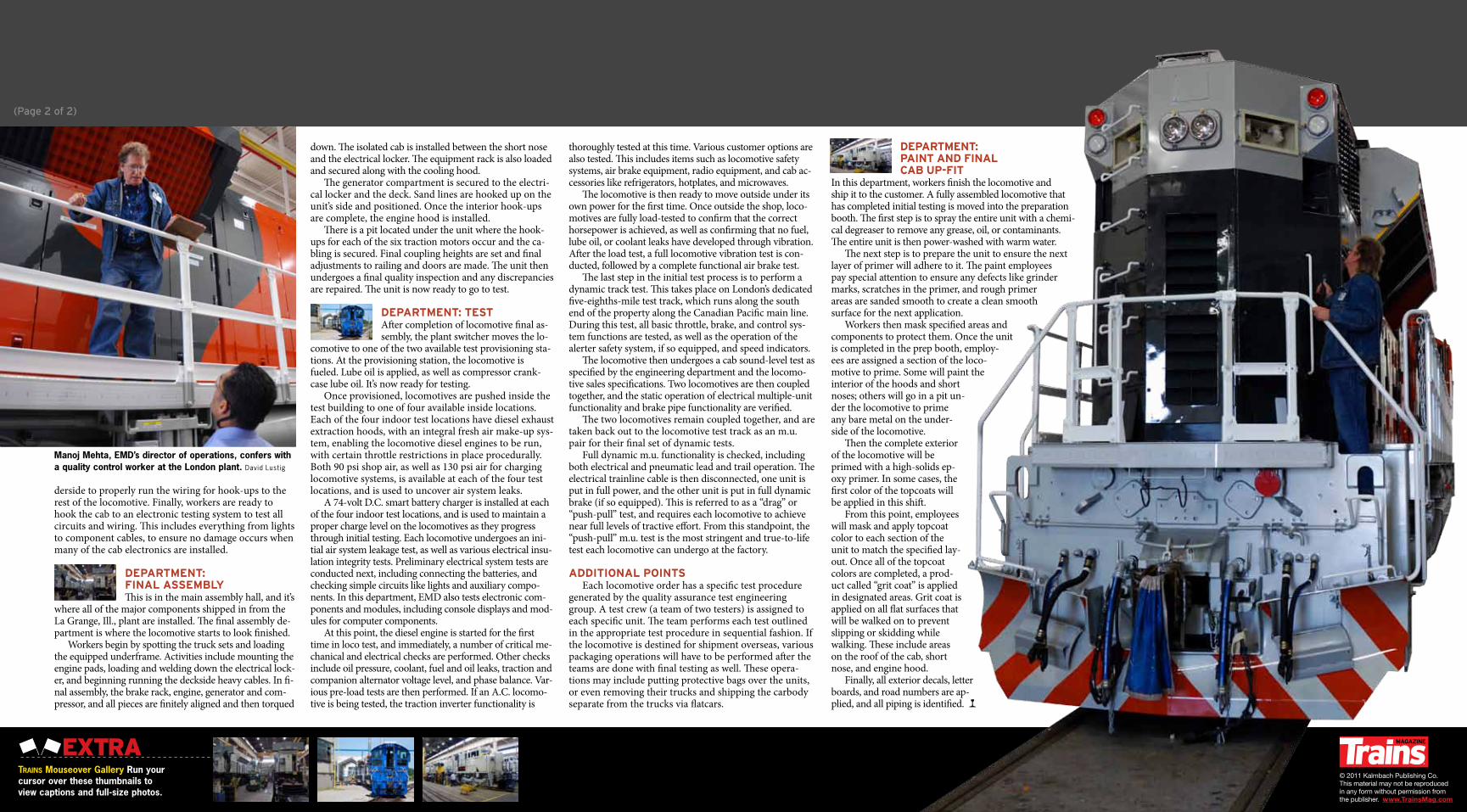
Manoj Mehta, EMD’s director of operations, confers with a quality control worker at the London plant. David Lustig
down. The isolated cab is installed between the short nose and the electrical locker. The equipment rack is also loaded and secured along with the cooling hood.
The generator compartment is secured to the electri-cal locker and the deck. Sand lines are hooked up on the unit’s side and positioned. Once the interior hook-ups are complete, the engine hood is installed.
There is a pit located under the unit where the hook-ups for each of the six traction motors occur and the ca-bling is secured. Final coupling heights are set and final adjustments to railing and doors are made. The unit then undergoes a final quality inspection and any discrepancies are repaired. The unit is now ready to go to test.
Department: teStAfter completion of locomotive final as-sembly, the plant switcher moves the lo-
comotive to one of the two available test provisioning sta-tions. At the provisioning station, the locomotive is fueled. Lube oil is applied, as well as compressor crank-case lube oil. It’s now ready for testing.
Once provisioned, locomotives are pushed inside the test building to one of four available inside locations. Each of the four indoor test locations have diesel exhaust extraction hoods, with an integral fresh air make-up sys-tem, enabling the locomotive diesel engines to be run, with certain throttle restrictions in place procedurally. Both 90 psi shop air, as well as 130 psi air for charging locomotive systems, is available at each of the four test locations, and is used to uncover air system leaks.
A 74-volt D.C. smart battery charger is installed at each of the four indoor test locations, and is used to maintain a proper charge level on the locomotives as they progress through initial testing. Each locomotive undergoes an ini-tial air system leakage test, as well as various electrical insu-lation integrity tests. Preliminary electrical system tests are conducted next, including connecting the batteries, and checking simple circuits like lights and auxiliary compo-nents. In this department, EMD also tests electronic com-ponents and modules, including console displays and mod-ules for computer components.
At this point, the diesel engine is started for the first time in loco test, and immediately, a number of critical me-chanical and electrical checks are performed. Other checks include oil pressure, coolant, fuel and oil leaks, traction and companion alternator voltage level, and phase balance. Var-ious pre-load tests are then performed. If an A.C. locomo-tive is being tested, the traction inverter functionality is
(Page 2 of 2)