Build 3D Scanner System based on Binocular Stereo Vision · II. THE PRINCIPLE OF BINOCULAR STEREO...
6
Build 3D Scanner System based on Binocular Stereo Vision Zhihua Lv College of Information Engineering, Northwest A&F University, Yangling, 712100, China Email: [email protected] Zhiyi Zhang* College of Information Engineering, Northwest A&F University, Yangling, 712100, China Email: [email protected] Abstract—This paper presents such a low-cost and simple 3D Scanner System. The necessary hardware is a hand-held line laser and two same standard cameras. The System can obtain 3D information of object and importantly this method is simple and effective. So it is very easy-to-use, and the results can be satisfied for normal users. Index Terms – scanner, binocular stereo vision, pinhole camera model, Sobel Operator I. INTRODUCTION The 3D Scanner is a device which can obtain the 3D information of object or scene. The purpose of a 3D scanner is usually to create a point cloud of geometric samples on the surface of the subject [1]. These points can be processed and reconstructed the shape of the object. If color information of each point is also able to be collected, the surface of the object which has colors can be reconstructed. The result called three dimensional models. There are a lot of methods for obtaining the 3D information of objects. According to different methods, it is usually divided into two types: contact and non-contact 3D scanners [1]. Contact 3D scanners need physical touch to get the 3D information. They usually has high precise. But they often need a long time to scan and it may damages the scanned object. Non-contact 3D scanners usually uses laser or structured lighting [2] to irradiate an object and get its reflection to calculate the 3D information. Compare to contact 3D scanner, its scanning is fast, its operation is simple, more importantly, it will not damage the scanned subject. But the disadvantage is that it maybe not precise. There are a lot of methods can finish 3D scanning. Each method has its different limitations, advantages and costs. The paper proposes a non-contact and low-cost 3D laser scanner system. This process will involve many technologies such as that how to make cameras able to get images, camera calibration, image processing, getting the center line from image and so on. But it is not necessary to discuss all technologies in this paper. In this system the necessary hardware is a hand-held line laser and two standard cameras. Two cameras are put at a straight line and they can't be moved when scanning. And the line laser irradiates an object vertically. Two images can be respectively got by using two cameras. There is a laser line in each image at the same time. With the position of laser line in two images, we can calculate the real position of points that lying on the laser line. By moving the laser like a paintbrush, the 3D data of the object are acquired until the scan results are smooth or satisfied for users. II. THE PRINCIPLE OF BINOCULAR STEREO VISION Binocular stereo vision is a way of getting 3D information from two 2D images. As we all know, the pinhole camera model how 3D scene points are transformed into 2D image points. The pinhole camera is a simple linear model for perspective projection as shown in Figure 1. Figure 1. Pinhole camera model In Figure 1, C, D points and A, B points can be constituted a straight line respectively. And two lines have a intersection. In this model, the obtained images are inverted images. In other words, the object image is upside down. In order to make problem convenient, the pinhole and the image plane can be swapped as shown in Figure 2[3]. JOURNAL OF COMPUTERS, VOL. 7, NO. 2, FEBRUARY 2012 399 © 2012 ACADEMY PUBLISHER doi:10.4304/jcp.7.2.399-404
Transcript of Build 3D Scanner System based on Binocular Stereo Vision · II. THE PRINCIPLE OF BINOCULAR STEREO...

Build 3D Scanner System based on Binocular Stereo Vision
Zhihua Lv
College of Information Engineering, Northwest A&F University, Yangling, 712100, China Email: [email protected]
Zhiyi Zhang*
College of Information Engineering, Northwest A&F University, Yangling, 712100, China Email: [email protected]
Abstract—This paper presents such a low-cost and simple 3D Scanner System. The necessary hardware is a hand-held line laser and two same standard cameras. The System can obtain 3D information of object and importantly this method is simple and effective. So it is very easy-to-use, and the results can be satisfied for normal users.
Index Terms – scanner, binocular stereo vision, pinhole camera model, Sobel Operator
I. INTRODUCTION The 3D Scanner is a device which can obtain the 3D
information of object or scene. The purpose of a 3D scanner is usually to create a point cloud of geometric samples on the surface of the subject [1]. These points can be processed and reconstructed the shape of the object. If color information of each point is also able to be collected, the surface of the object which has colors can be reconstructed. The result called three dimensional models.
There are a lot of methods for obtaining the 3D information of objects. According to different methods, it is usually divided into two types: contact and non-contact 3D scanners [1].
Contact 3D scanners need physical touch to get the 3D information. They usually has high precise. But they often need a long time to scan and it may damages the scanned object.
Non-contact 3D scanners usually uses laser or structured lighting [2] to irradiate an object and get its reflection to calculate the 3D information. Compare to contact 3D scanner, its scanning is fast, its operation is simple, more importantly, it will not damage the scanned subject. But the disadvantage is that it maybe not precise.
There are a lot of methods can finish 3D scanning. Each method has its different limitations, advantages and costs. The paper proposes a non-contact and low-cost 3D laser scanner system. This process will involve many technologies such as that how to make cameras able to get images, camera calibration, image processing, getting the center line from image and so on. But it is not necessary to discuss all technologies in this paper.
In this system the necessary hardware is a hand-held line laser and two standard cameras. Two cameras are put at a straight line and they can't be moved when scanning. And the line laser irradiates an object vertically. Two images can be respectively got by using two cameras. There is a laser line in each image at the same time. With
the position of laser line in two images, we can calculate the real position of points that lying on the laser line. By moving the laser like a paintbrush, the 3D data of the object are acquired until the scan results are smooth or satisfied for users.
II. THE PRINCIPLE OF BINOCULAR STEREO VISION Binocular stereo vision is a way of getting 3D
information from two 2D images. As we all know, the pinhole camera model how 3D scene points are transformed into 2D image points. The pinhole camera is a simple linear model for perspective projection as shown in Figure 1.
Figure 1. Pinhole camera model
In Figure 1, C, D points and A, B points can be constituted a straight line respectively. And two lines have a intersection. In this model, the obtained images are inverted images. In other words, the object image is upside down. In order to make problem convenient, the pinhole and the image plane can be swapped as shown in Figure 2[3].
JOURNAL OF COMPUTERS, VOL. 7, NO. 2, FEBRUARY 2012 399
© 2012 ACADEMY PUBLISHERdoi:10.4304/jcp.7.2.399-404

Figure 2. Swap pinhole and image plane
As shown in Figure 3, set up a coordinate system. The left camera is at the origin of coordinates and the right camera is at the x-axes. The y-axes take the downward direction as positive. Two cameras look toward the positive direction of z-axes. P1, P2 are the P in left, right camera on the imaging point, respectively. L is the distance of two cameras.
Figure 3. Binocular Stereo Vision
O1, O2 are at the x-axes, and the two cameras are the same type. We can know Y1 = Y2 easily. In other words, O1P1 and O2P2 are on the same plane so that they have an intersection. In Figure 3, the intersection is point P. By mathematical relations, the equation of two straight lines is:
⎪⎪⎩
⎪⎪⎨
⎧
===−−
===
sZZ
YY
LXLXPO
tZZ
YY
XXPO
22222
11111
:
:
(1)
Our target is to calculate the coordinate of point P. It is necessary to know the value of t or s. By equation (1), the value of t can be calculated as following:
11221
2
LYYXYXLYt
+−=
(2)
And by the equation of the O1P1 straight line in equation (1), the P(X,Y,Z) can be presented as following equation (3):
⎪⎩
⎪⎨
⎧
===
tZZtYYtXX
1
1
1
(3)
From equation (2) and (3), the coordinate of point P can be calculated.
III. TECHNICAL SCHEME The binocular stereo vision system is usually divided
into five parts: Image Acquisition, Camera Calibration, Image Pre-processing and Feature Extraction, Stereo Matching, Distance Determination [4][5][6]. These five parts have their main influencing factor and technique respectively. Every part can use different methods.
In order to make problem simple, in this paper, we divide system into four parts: Image Acquisition, Getting Necessary Parameters of Cameras, Image Pre-processing and The Center of Line Structure Laser Extracting, Points Matching and Distance Determination. These four parts use these names which are easier to be known. Because some parts of this system are not so complicated as usually.
A. Image Acquisition Acquiring 2D image is the first step to obtain the 3D
information of an object in stereo vision. The result is more precise with the higher resolution of image. But the higher resolution image will cost much time so that making the system slow. In this paper, the 320 * 240 size images are used for scanning. But in practical application, 640 * 480 size images at least are necessary. If the system wants to adapt to complex environment, it needs to modify the acquiring images with some image property such as brightness, contrast, sharpness and so on.
In this system, two cameras are put at a straight line as shown in Figure 3. The distance can be known by measuring.
B. Getting Necessary Parameters of Cameras In general, a 3D scanner system needs very complex
calibration. More importantly, this work needs user to complete, but user often cannot finish it. So we want to simplify this process as possible.
As shown in Figure 3, we know that the necessary parameters are the distance of two cameras and the focal length of cameras. Z1, Z2 are equal to focal length. The distance of two cameras can be known easily. In general, we set this parameter to 5cm – 10 cm. Next is surveying focal length. Many cheap cameras have a fixed focal length and we can know it directly. If the camera has automatic focus, we need to survey it. In this paper, the method of surveying focal length is not discussed.
C. Image Pre-processing and The Center of Line Structure Laser Extracting The images from cameras include a variety of noise
and distortion. In order to highlight useful information and limit useless information, it is necessary to
400 JOURNAL OF COMPUTERS, VOL. 7, NO. 2, FEBRUARY 2012
© 2012 ACADEMY PUBLISHER

preprocess the original image. There are two purposes. Firstly, improve the definition of images. Secondly, make images more easy to process by computer and convenient for feature analysis.
In general, the scanned subject only has about 1/3 in the image. So it is necessary to limit the scanning range. It can improve the scanning speed. More importantly, we can eliminate the background effectually. The simple method is to draw a rectangle in the image. We consider that out of rectangle is background.
The laser provides a sharp contrast to the environment. But it is also difficult to find out which pixel is the laser and which pixel is the background in two images. Here we provide two methods to get the center of line structure laser. The two methods have a common step, convert image to grayscale. The source image is 3-channels (RGB), and it needs to be converted to 1-channel. It can use the average value of R, G, B to instead of every pixels.
1) Simple Method: The first method is simple and fast, but precise is low. Image Binarization is typically a thresholding operation on a grayscale image. The thresholding is given by user when scanning. If a pixel value is greater than the thresholding, it will be set to max-value, or be set to zero. After binarization, the max-value pixels can be considered as the laser line. But the laser has width and only the center line is necessary. As shown in Figure 4, with scanning every row of an image as the red arrow, the left boundary and right boundary of can be obtained.
Figure 4. Simple Method to find the center of laser line
L is the left boundary, and R is the right boundary. The center of line can be calculated as equation (4). It is easily to be known that the result is an integer or a half of an integer. So it is not precise.
2
RLC +=
(4)
2) The Center-of-Gravity Method based on Sobel Operator: The second method can get higher precise, but will reduce the speed. This method is divided into three steps as following:
a) Roughly find the center: In order to know the precise center, the first step is to find a rough center.
Then it can be considered that the true center is close to this rough center. Because the rough center is not precise, there are many methods to find it. This paper provides a simple method [7]. As shown in Figure 5, the red (high color) is a 1*3 size mask. To every row, the mask move from left to right and calculate the sum of pixel value. And the max sum place can be found out. Then the middle of this place can be consider as the rough center. But it is also possible that there is not laser line at a row. So user can give a thresholding. Only if the center pixel value of the window is greater than the thresholding, it can be consider as the rough center.
Figure 5. The red is the window to find rough center
b) Find the left boundary and right boundary with sobel operator: The ideal laser line is a gaussian distribution in a row. Next problem is how to find a range and the pixel values in this range are the most possible to reflect the Gaussian Distribution. This paper uses the sobel operator to find boundary. The Sobel Operator is used in image processing, particularly within edge detection algorithms [8].
⎥⎥⎥
⎦
⎤
⎢⎢⎢
⎣
⎡
+++
−−−
⎥⎥⎥
⎦
⎤
⎢⎢⎢
⎣
⎡
+−+−+−
121000121
101202101
Figure 6. The left is vertical operator, the right is horizontal operator [9]
Since all laser lines are vertical in this paper, the vertical operator is used to calculate the boundaries. If the laser lines are horizontal on images, we can use the horizontal operator. At (a) step above, the rough center has been found out. As shown in Figure 7, w is a half of range. In general, w can be 15 (pixels). Then in this range, from left to right, every pixel is calculated by vertical Sobel Operator.
Figure 7. The range of using Sobel Operator
As shown in Figure 8, it’s a pixel matrix. Every element is the pixel value. The middle element is present element. From this matrix and vertical Sobel Operator, the result can be presented as following equation (5).
lu u ru l m r
ld d rd Figure 8. Example
( ) ( )lrldlurdruS 22 −+−−+= (5)
JOURNAL OF COMPUTERS, VOL. 7, NO. 2, FEBRUARY 2012 401
© 2012 ACADEMY PUBLISHER

In equation (5), S can be considered as the rate of pixel change. Here a thresholding is necessary. In the range of using Sobel Operator, the leftmost place that S is greater than the thresholding is the left boundary, and the rightmost place is the right boundary.
c) Calculate the center with the Center-of-Gravity Method [10]: The left boundary and right boundary has been known in every rows. The precise center is calculated as following equation (6):
∑=
=rp
lpi i
ii
NNPC
(6)
D. Points Matching and Distance Determination At this step, the first problem is how to find matching
points. This problem has been argued over several decades in computer vision. It is the most important part in stereo vision. In general, this problem is very complex. In this paper, we simply this process. It is the reason why we put two cameras at the same line(x-axes).
As shown in Figure 3 and mentioned above, Y1 = Y2. And the line laser irradiates the object vertically. As a result, a point in left image and the matching point in right image are at the same line in the image array. As shown in Figure 9, the point (1, 3) in left image is matching the point (1, 4) in right image.
Figure 9. The green is laser line, the red is the center line
In the Figure 10, u-axes and v-axes are the coordinate system of image. Left image and right image has this coordinate system, respectively. L is the distance of two cameras.
In order to use equation (1)(2)(3) for calculating 3D information, it is necessary to transform 2D coordinate to 3D coordinate in space coordinate system. As shown in Figure 5, our purpose is to transform P1’(U1, V1) and P2’(U2, V2) into P1(X1, Y1, Z1) and P2(X2, Y2, Z2) in Figure 3.
Figure 10. 2-Dimensional points coordinate
Transforming coordinate between 2D and 3D is a problem of linear algebra obviously. In following is the convert equation:
⎥⎥⎥
⎦
⎤
⎢⎢⎢
⎣
⎡
⎥⎥⎥⎥⎥⎥
⎦
⎤
⎢⎢⎢⎢⎢⎢
⎣
⎡
−
−
=⎥⎥⎥
⎦
⎤
⎢⎢⎢
⎣
⎡
1002
102
01
1
1
1
1
1
VU
f
h
w
ZYX (7)
⎥⎥⎥
⎦
⎤
⎢⎢⎢
⎣
⎡
⎥⎥⎥⎥⎥⎥
⎦
⎤
⎢⎢⎢⎢⎢⎢
⎣
⎡
−
+−
=⎥⎥⎥
⎦
⎤
⎢⎢⎢
⎣
⎡
1002
102
01
2
2
2
2
2
VU
f
h
Lw
ZYX (8)
In equation (7) and (8), w is the width of image, h is the height of image. Then the 3D coordinate of P1, P2 can be known. And as equation (1)(2)(3), the coordinate of P point can be calculated. By moving the laser, two cameras are able to get images continuously. Then the 3D data can be calculated until the scan results are satisfied by users.
IV. EXPERIMENTAL RESULTS AND CONCLUSION The programs of this system are all developed in Qt
Creator environment. The used library includes OpenCV and OpenGL. The two cameras are Logitech QuickCam Pro 9000. The laser is green. The computer is Pentium(R) Dual-Core CPU T4300 @ 2.10GHz.
Figure 11. The result of Getting center line
402 JOURNAL OF COMPUTERS, VOL. 7, NO. 2, FEBRUARY 2012
© 2012 ACADEMY PUBLISHER
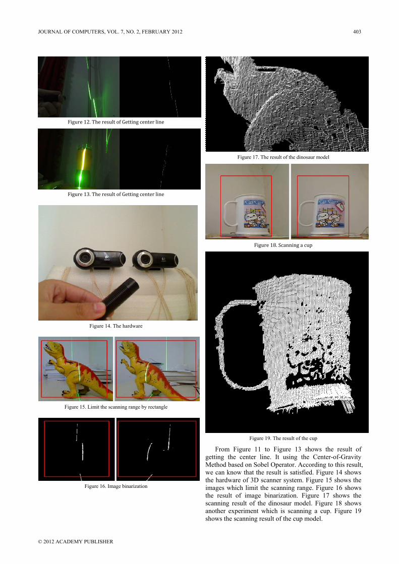
Figure 12. The result of Getting center line
Figure 13. The result of Getting center line
Figure 14. The hardware
Figure 15. Limit the scanning range by rectangle
Figure 16. Image binarization
Figure 17. The result of the dinosaur model
Figure 18. Scanning a cup
Figure 19. The result of the cup
From Figure 11 to Figure 13 shows the result of getting the center line. It using the Center-of-Gravity Method based on Sobel Operator. According to this result, we can know that the result is satisfied. Figure 14 shows the hardware of 3D scanner system. Figure 15 shows the images which limit the scanning range. Figure 16 shows the result of image binarization. Figure 17 shows the scanning result of the dinosaur model. Figure 18 shows another experiment which is scanning a cup. Figure 19 shows the scanning result of the cup model.
JOURNAL OF COMPUTERS, VOL. 7, NO. 2, FEBRUARY 2012 403
© 2012 ACADEMY PUBLISHER

The scanning time is about 10-20s. As shown in Figure 17 and Figure 19, one side of the dinosaur model and cup model can be reconstructed. And the 3D laser scanner doesn’t need complex calibration.
According to the experimental result, we can know this method can reconstruct the 3D model basically. And the precision can be satisfied by normal users. In order to get better precision, there are two methods. A method is making environment black as possible when scanning. It will make laser and background more contrast. In image preprocessing, the results will be better. Another method is increasing the resolution of images. It will make images have more particulars of object so that the result model has more points.
ACKNOWLEDGMENT This work was supported by the Scientific Research
Foundation from Northwest Agriculture & Forest University of China No. Z111020721, the Special Fund from the Central Collegiate Basic Scientific Research Bursary No. Z109021004, Scientific Research Foundation for the Returned Overseas Chinese Scholars, State Education Ministry No. K314020901 and China National Undergraduates Innovating Experimentation Projection.
REFERENCES [1] http://en.wikipedia.org/wiki/3d_scanner [2] Douglas Lanman, Gabriel Taubin: "Build Your Own 3D
Scanner: 3D Photography for Beginners", SIGGRAPH 2009 Course Notes, Wednesday, August 5, 2009.
[3] Gary Bradski, Adrian Kaebler, "Learning OpenCV - Computer Vision with the OpenCV Library", September 2008: First Edition.
[4] Ramesh.C.Jain, Thomas.O.Binford, "DIALOGUE Ignorance, Myopia, and Naivete in Computer Vision System", Vol. 53, No. 1, Jan, pp, 112-117, 1991
[5] Ron Mcclamrock, "Marr's Three Levels: A Re-Evaluation, Minds Mach", Vol.1, No.2, pp. 185-196, 1991
[6] Ling Li, "The research on 3-Dimensional reconstruction based on binocular stereo vision", Master, thesis, 2005
[7] Wu Jiayong, Wang Pingjiang, Chen Jihong, Wu Mengliang, " Method of Linear Structured Light Sub-pixel Center Position Extracting Based on Gradient Barycenter", Journal of Image and Graphics, Jul. 2009. 1006-8961(2009)07-1354-07
[8] http://en.wikipedia.org/wiki/Sobel_operator [9] Xiong Huiyuan, Zong Zhijian, Gao Qun, Chen Chenghe,
"Precise method for extracting center of structured light stripe", Computer Engineering and Applications, 2009, 45(10): 235-237
[10] Li Zhongwei, Wang Congjun, Shi Yusheng, "An Algorithm for Detecting Center of Structured Light Stripe Combining Gradient Sharpening with Barvcenter Method", Journal of Image and Graphics, 1006-8961(2008) 01-0064-05
Zhihua Lv GuangXi Province, China. Birthdate: Dec, 1989. is undergraduate in College of Information Engineering, Northwest A&F University. And research interests on Computer Graphics and Digital Image Processing.
He is a junior student of College of Information Engineering, Northwest A&F University.
Zhiyi Zhang ShanXi Province, China. Birthdate: Sep, 1974. is Electronic and Information Engineering Ph.D., graduated from Faculty of Engineering, Graduate School of Engineering Iwate University, Japan. And research interests on Computer Aided Design, Computer Aided Geometric Design, Computer Graphics.
He is a associate professor of College of Information Engineering, Northwest A&F University.
404 JOURNAL OF COMPUTERS, VOL. 7, NO. 2, FEBRUARY 2012
© 2012 ACADEMY PUBLISHER