Bugbot Teacher’s Guide - Illinois State University · in Make magazine as ʻthe Beetlebot,ʼ the...
28
Bugbot Teacherʼs Guide Introduction Welcome to the world of Educational Robotics. If you are new to teaching with Educational Robotics, this guide will take you through the material step-by-step so that you can quickly have your students off and running. If you have already used Educational Robotics in your previous instruction, this guide will provide you with reproducible handouts and materials, designed to be accessible for students. The culminating activity in this guide is the construction of the Bugbot. Each Bugbot kit is a self-contained robot that requires no programming. Bugbot uses momentary switches as bump-sensors, which allow the robot to move around obstacles and perform seemingly-complex navigation within its environment. This type of robotics, widely referred to as BEAM (Biology, Electronics, Aesthetics, and Mechanics), was pioneered by Mark Tilden. Designs for the Bugbot were popularized on the internet and in Make magazine as ʻthe Beetlebot,ʼ the original design is attributed to Jerome Demers, who was just sixteen years old when he created the robot. The Bugbot included in these kits is nearly identical to these models, with minor changes to make the building process more tractable for a classroom setting. The Bugbot Teacherʼs Guide, as well as the Bugbot Student Guide, are released under the Creative Commons noncommercial, share-share-alike license (c b n a http:// creativecommons.org/licenses/by-sa/3.0/us/ ), except where otherwise noted. This license allows you to make copies of documents, as well as remix the materials without worry. If you publish the remixed materials, however, you must attribute credit to the original and license the derivatives under the same Creative Commons license. Above all, we hope that this program is rewarding both for your students and for you, the educator. We believe that education is a dialog and that learning is a discussion. We at RJ&K encourage you to build your own Bugbot, with your students, and to continue to explore together the wonderful world of BEAM and STEM (Science, Technology, Engineering, and Mathematics). Kindest Regards, RJ Linton CEO/CIO RJ and K Inc. Web: www.rjandk.com Email: [email protected] Phone: 309-339-5345 Bugbot Teacher’s Guide c b n a Except where otherwise noted http://creativecommons.org/licenses/by-nc-sa/3.0/us/ Page 1
Transcript of Bugbot Teacher’s Guide - Illinois State University · in Make magazine as ʻthe Beetlebot,ʼ the...

Bugbot Teacherʼs Guide Introduction
! Welcome to the world of Educational Robotics. If you are new to teaching with Educational Robotics, this guide will take you through the material step-by-step so that you can quickly have your students off and running. If you have already used Educational Robotics in your previous instruction, this guide will provide you with reproducible handouts and materials, designed to be accessible for students.
! The culminating activity in this guide is the construction of the Bugbot. Each Bugbot kit is a self-contained robot that requires no programming. Bugbot uses momentary switches as bump-sensors, which allow the robot to move around obstacles and perform seemingly-complex navigation within its environment. This type of robotics, widely referred to as BEAM (Biology, Electronics, Aesthetics, and Mechanics), was pioneered by Mark Tilden. Designs for the Bugbot were popularized on the internet and in Make magazine as ʻthe Beetlebot,ʼ the original design is attributed to Jerome Demers, who was just sixteen years old when he created the robot. The Bugbot included in these kits is nearly identical to these models, with minor changes to make the building process more tractable for a classroom setting.
! The Bugbot Teacherʼs Guide, as well as the Bugbot Student Guide, are released under the Creative Commons noncommercial, share-share-alike license (c b n a http://creativecommons.org/licenses/by-sa/3.0/us/ ), except where otherwise noted. This license allows you to make copies of documents, as well as remix the materials without worry. If you publish the remixed materials, however, you must attribute credit to the original and license the derivatives under the same Creative Commons license.
! Above all, we hope that this program is rewarding both for your students and for you, the educator. We believe that education is a dialog and that learning is a discussion. We at RJ&K encourage you to build your own Bugbot, with your students, and to continue to explore together the wonderful world of BEAM and STEM (Science, Technology, Engineering, and Mathematics).
Kindest Regards,
RJ LintonCEO/CIORJ and K Inc. Web: www.rjandk.comEmail: [email protected]: 309-339-5345
Bugbot Teacher’s Guide
c b n a Except where otherwise noted http://creativecommons.org/licenses/by-nc-sa/3.0/us/ Page 1

Basic Electrical Circuits" 4Observations and Exploration" 4
Circuit Drawing" 6
Electronics" 7Schematic Practice " 8
Schematic Symbols" 9
Ohmʼs Law" 10The Water Analogy " 10
Graphical Representation of Ohmʼs Law" 11
Algebraic Manipulation of Ohmʼs Law" 12
Ohmʼs Law Concepts " 12
Resistor Man" 14Parts" 14
Tools " 14
Soldering" 15
Bugbot " 16Parts and Tools" 16
Preparation" 17
Momentary Switches" 17
Motor Preparation" 19
Table of Contents
c b n a Except where otherwise noted http://creativecommons.org/licenses/by-nc-sa/3.0/us/ Page 2

Bugbot Assemblies" 20
Bugbotʼs Body " 21
Bugbotʼs Tail" 22
Switches " 22
Attaching the motors " 23
Attaching the tail" 23
Final Electrical Connections " 24
Adding some friction" 25
Antennae " 25
Helping Hands (Optional)" 27Tools " 27
Parts" 27
Assembly" 28
Table of Contents
c b n a Except where otherwise noted http://creativecommons.org/licenses/by-nc-sa/3.0/us/ Page 3

Basic Electrical CircuitsObservations and Exploration
Basic Electrical Circuits
c b n a Except where otherwise noted http://creativecommons.org/licenses/by-nc-sa/3.0/us/ Page 4
Description: Basic Electrical Circuits
Electrical circuits are connected electrical components which form a closed loop. In other words, if you begin tracing an electrical circuit with a pencil, eventually you will return to the location on the circuit from which you started.
Name:
Partnerʼs Name:
“Nothing is too wonderful to be true if it be consistent with the laws of nature.”--Michael Faraday
Flashlight
To begin to develop an understanding of electrical circuits, it is best to build one. Here, you will construct a flashlight. You will explore how the circuit works and try to determine the important aspects of the circuit. To finish this activity, you will need some aluminum foil (optionally a short piece of 18 - 20 gauge wire) a two D-cells, and one mini flashlight bulb.
Exploration
Using the aluminum foil, one of the D-Cells, and the mini flashlight bulb, try to build a circuit to light the light bulb. Answer the following questions.
1. Imagine that your circuit (the “circle”, or arrangement of the materials needed to light the bulb) is like a bunch of pipes carrying water. What is flowing through the “pipes” of your circuit ?

Basic Electrical Circuits
c b n a Except where otherwise noted http://creativecommons.org/licenses/by-nc-sa/3.0/us/ Page 5
2. Note any observations about the system here, such as the brightness of the lightbulb or the length of foil used for connections.
3. Does the arrangement of the materials matter in lighting the light bulb?
4. Does the length or size of aluminum foil matter in lighting the bulb?
5. What happens when you add the second battery to the circuit?
6. Is a complete circle needed to light the bulb? (Do ALL the pieces need to be connected or touching?)

Circuit Drawing
Basic Electrical Circuits
c b n a Except where otherwise noted http://creativecommons.org/licenses/by-nc-sa/3.0/us/ Page 6
7. If you were to draw a picture of the circuit, what would it look like? Draw your picture here.
! page 2 of 4
TASK 3:
Alert one of the camp counselors when you are done
1. Let the counselors know you have finished your observations.
2.We will use the data you recorded in your tables, and your group’s answers to the questions to compare results with all the other groups.
!
TASK 2: Lighting a Light Bulb
1. Try lighting the light bulb. (Hint: The word “circuit” means the same as “circle”).
2. Record any observations you feel are im-portant on your worksheet, like the order of the objects, what parts have to touch what, etc.
3. Keep track of (record on your worksheet) any measurements you make, and try to keep the information organized in a useful way.
4.Once you are able to light the light bulb, try using a 2nd battery.
5.Once you are able to light the bulb, try us-ing different size pieces of foil.
6.Answer questions 1 through 6 on your worksheet.
TASK 1: Prepare for activities
1. First, find the worksheet located at the end of this packet.
2.Fill in your name, your partners names and your counselor’s name.
3. As you do your activities, be sure that everyone has a chance to take part in some part of the activity.

Electronics
Electronics
c b n a Except where otherwise noted http://creativecommons.org/licenses/by-nc-sa/3.0/us/ Page 7
Name:
Partnerʼs Name:
“I haven't failed, I've found 10,000 ways that don't work”--Thomas Alva Edison
SchematicsSchematicsSchematics
One of the primary methods of communicating ideas about electronics is the schematic. A schematic is simply a drawing of a collection of connected symbols. All of the symbols a designer chooses to use come from a standard collection of electronics symbols. You may have heard of several types of electronic components with symbols that are used on a schematic. For example, you have probably heard of a transistor, resistor, or a battery. Each of these electronic components have a standard symbol used by circuit designers when they create schematics.
One of the primary methods of communicating ideas about electronics is the schematic. A schematic is simply a drawing of a collection of connected symbols. All of the symbols a designer chooses to use come from a standard collection of electronics symbols. You may have heard of several types of electronic components with symbols that are used on a schematic. For example, you have probably heard of a transistor, resistor, or a battery. Each of these electronic components have a standard symbol used by circuit designers when they create schematics.
One of the primary methods of communicating ideas about electronics is the schematic. A schematic is simply a drawing of a collection of connected symbols. All of the symbols a designer chooses to use come from a standard collection of electronics symbols. You may have heard of several types of electronic components with symbols that are used on a schematic. For example, you have probably heard of a transistor, resistor, or a battery. Each of these electronic components have a standard symbol used by circuit designers when they create schematics.
Battery Cell Resistor Transistor
The picture on the left is an example of a schematic. You can see two Battery Cells in this schematic as well as two motors and three switches.
Description: Schematics and Components
Just like when someone learns to snowboard, rock climb, or skydive, building robots has certain vocabulary everyone needs to know. The vocabulary of robotics is electronics and mechanics. In this guide we begin the discussion of electronics.

Schematic Practice
Electronics
c b n a Except where otherwise noted http://creativecommons.org/licenses/by-nc-sa/3.0/us/ Page 8
Schematics
Using the provided symbol chart and the grid space below, attempt to draw a schematic of a simple circuit to light a LED with a single Battery Cell. Include all of the components you think would be required to make the circuit useful.

Schematic Symbols
Electronics
c b n a Except where otherwise noted http://creativecommons.org/licenses/by-nc-sa/3.0/us/ Page 9
Schematics
Below is a set of standard electronic component symbols.
Ammeter Battery Capacitor
Battery Cell Diode Light Emitting Diode (LED)
Motor Ohm Meter Photodiode
Phototransistor Resistor DPST Switch
NPN Transistor Volt Meter Variable Resistor
Wire (Connects Components) Wire Connections Wire Jump

Ohm’s LawThe Water Analogy
Ohm’s Law
c b n a Except where otherwise noted http://creativecommons.org/licenses/by-nc-sa/3.0/us/ Page 10
Name:
Partnerʼs Name:
"...a physicist who professed such heresies is unworthy to teach science."--German Minister of Education from 1001 Dumbest
Things Ever Said By Steven D. Price
The Water Analogy
Recall the image from the exploratory activity of your electric circuit being like a system of pipes with water running through them. In this comparison, the electricity in your circuit is like the water moving through the pipes and the individual droplets of water would be like the individual electrons. The voltage would be like the amount of water pressure in the pipes. A battery providing the voltage, then, would work like a pump station pushing water through the pipes. The electric current (which is measured in Amperes) would be like the rate of water flow. Resistance in your circuit can be thought of as something that blocks the pipes and keeps the water from moving easily. For example, maybe the pipe is clogged with sand or gravel. In an electric circuit, the actual metal atoms that the wire is made of act as the gravel or sand would, resisting the flow of the electricity. If resistance in your circuit stays the same, then the larger the voltage, the higher the electric current will be. Just like in water pipes, the more pressure there is, the faster the water flows.
“George Simon Ohm lived from 1789 to 1854. He was a mathematics teacher. He became interested in the new field of electricity. At the time, many physicists didn't use mathematics ... Ohm combined his mathematics and the results of his electrical experiments to produce Ohm's Laws.”
--http://www.shodor.org/cserd/Resources/Activities/OhmsLaw/
Description: Ohmʼs Law
In this activity, you will see how Ohmʼs Law relates current, voltage, and resistance in a circuit. Ohmʼs Law for simple circuits is usually expressed as V = IR. Electric current (I) is the flow of electricity (electrons) through a wire in response to an electric potential (voltage, V). Collisions of electrons with atoms in the wire are expressed as the resistance (R) of that material.

Graphical Representation of Ohmʼs Law
Ohm’s Law
c b n a Except where otherwise noted http://creativecommons.org/licenses/by-nc-sa/3.0/us/ Page 11
Graphical Representation of Ohmʼs Law
1. Look at the following data table. The values of voltage and current for a simple circuit, with only one resistor (2 Ohms) and a battery cell, are listed.
2. Use the information from the data table to graph the relationship on the current–voltage graph below.
0
2
4
6
8
10
0 1/2 1 1 1/2 2 2 1/2 3 3 1/2 4 4 1/2 5
Ohmʼs Law
Volta
ge “V
”
Current “I”
Data TableData TableData Table
Battery Voltage “V”(Volts)
Resistance of Resistor “Ω” (Ohms)
Current, “I” (Amperes)
0 2 01 2 ½2 2 14 2 25 2 2 ½6 2 38 2 4
10 2 5

Algebraic Manipulation of Ohmʼs LawOhmʼs Law Concepts
Ohm’s Law
c b n a Except where otherwise noted http://creativecommons.org/licenses/by-nc-sa/3.0/us/ Page 12
Various Mathematical Versions of Ohmʼs Law
The following graphic is a common representation of the algebraic manipulations of Ohmʼs Law. This type of image acts as a nemonic for the algebra one would have to do for various uses of Ohmʼs law. Notice that Ohmʼs Law is also related to Power.
Properties of Ohmʼs Law
Knowing the various arrangements of Ohmʼs Law, and the shape of a typical graph of the parameters of Ohmʼs Law, answer the following questions.
1. Note the shape of the Current-Voltage graph, is Ohmʼs Law a straight line (linear relationship) or more curvy (curvilinear relationship)?

Ohm’s Law
c b n a Except where otherwise noted http://creativecommons.org/licenses/by-nc-sa/3.0/us/ Page 13
2. The “steepness” of the graph is called its slope. Looking back at the graph you drew, what do you think the slope of the graph represents from Ohmʼs Law -- Voltage, Current, or Resistance?
3. Think back to the graph of Ohmʼs Law for a circuit with one resistor. What would happen if you added another resistor? Would another resistor make the resistance of the circuit bigger or smaller?
4. So, then would it be easier or harder for the electricity go through the circuit?
5. Would the graph be steeper or shallower? Why?
6. What would adding another resistor do to the electric current in the circuit?
Resistor ManPartsTools
Resistor Man
c b n a Except where otherwise noted http://creativecommons.org/licenses/by-nc-sa/3.0/us/ Page 14
Name:
Partnerʼs Name:
"It's the little details that are vital. Little things make big things happen."--John Wooden
Resistor Man Parts and Tools Parts and Tools
Resistor Man is a sculpture built from various resistors. The values and colors of the resistor do not matter.
Tools:
1. Helping Hands (Optional)
2. Soldering Iron
Parts:
1. Various Resistors
Description: Resistor Man
Resistor Man provides a fun way to learn basic soldering skills. These skills are the foundation skills for complete advanced electronics projects.
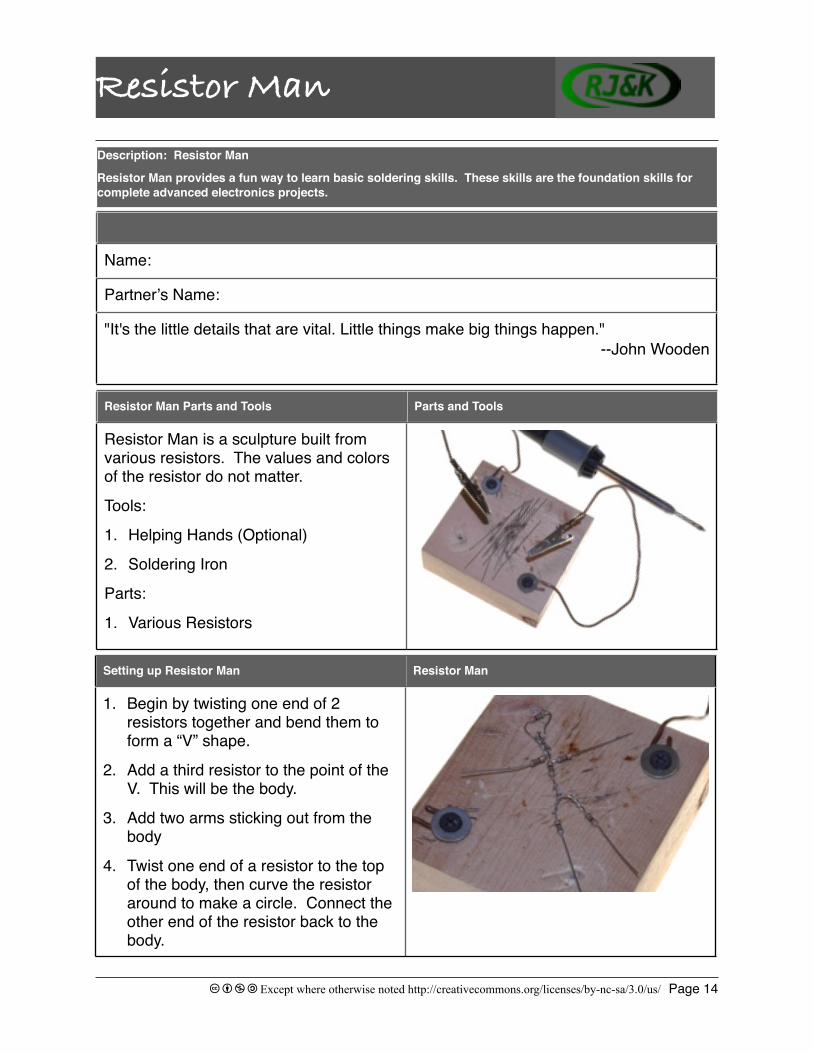
Setting up Resistor Man Resistor Man
1. Begin by twisting one end of 2 resistors together and bend them to form a “V” shape.
2. Add a third resistor to the point of the V. This will be the body.
3. Add two arms sticking out from the body
4. Twist one end of a resistor to the top of the body, then curve the resistor around to make a circle. Connect the other end of the resistor back to the body.
Soldering
Resistor Man
c b n a Except where otherwise noted http://creativecommons.org/licenses/by-nc-sa/3.0/us/ Page 15
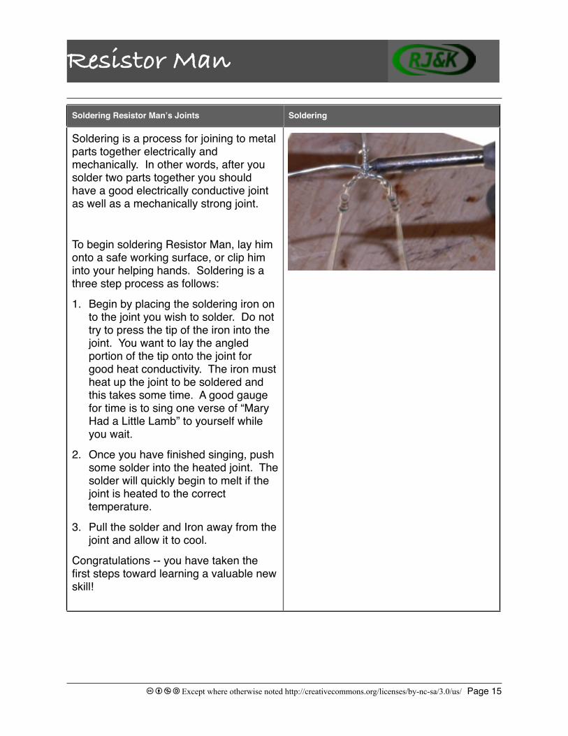
Soldering Resistor Manʼs Joints Soldering
Soldering is a process for joining to metal parts together electrically and mechanically. In other words, after you solder two parts together you should have a good electrically conductive joint as well as a mechanically strong joint.
To begin soldering Resistor Man, lay him onto a safe working surface, or clip him into your helping hands. Soldering is a three step process as follows:
1. Begin by placing the soldering iron on to the joint you wish to solder. Do not try to press the tip of the iron into the joint. You want to lay the angled portion of the tip onto the joint for good heat conductivity. The iron must heat up the joint to be soldered and this takes some time. A good gauge for time is to sing one verse of “Mary Had a Little Lamb” to yourself while you wait.
2. Once you have finished singing, push some solder into the heated joint. The solder will quickly begin to melt if the joint is heated to the correct temperature.
3. Pull the solder and Iron away from the joint and allow it to cool.
Congratulations -- you have taken the first steps toward learning a valuable new skill!

BugbotParts and Tools
Bugbot
c b n a Except where otherwise noted http://creativecommons.org/licenses/by-nc-sa/3.0/us/ Page 16
Name:
Partnerʼs Name:
Can you draw a circuit diagram that describes the forward and reverse motion of Bugbot? On a separate sheet of paper, give it a try. Hint: Remember to take into account the position of the momentary switches.
Inventorying Bugbotʼs parts Parts and Tools
Anytime you begin an assembly project, it is wise to locate each part in the kit. The parts that should be in your Bugbot kit are:
1. Two DC motors
2. Two momentary switches
3. 1 piece of Aluminum
4. 1 piece of 18 gauge wire
5. 4 pieces of shrink tubing
6. 1 wooden bead
7. 3 paper clips
8. 1 AA battery holder
9. 1 slide switch
Required Tools:
1. Needle nose pliers
2. Hot glue gun
3. Soldering iron
4. Side cutters
5. Safety lighter
6. Wire strippers
Description: The Bugbot is a clever little robot that is programed with solder. In other words, there is no way to reprogram Bugbot after it has already been assembled. Instead, the behavior of Bugbot is determined during operation by the direction of the flow of electricity through the Bugbotʼs motors.

PreparationMomentary Switches
Bugbot
c b n a Except where otherwise noted http://creativecommons.org/licenses/by-nc-sa/3.0/us/ Page 17
Soldering the Momentary Switches Switch Orientation and wire bend.
In this step we will assemble Bugbotʼs sensors. Each sensor is made up of an antenna attached to a momentary switch that acts as a “feeler.” Weʼll assemble the antennae later, for now we are just going to worry about the momentary switches.
NOTES:
1. Be careful not to lay the soldering iron on plastic parts of the switches.
2. Be careful not to over heat the switch tabs. Over heating can cause the switches to melt.
3. Try to keep the insulation of the wires as tight against the solder joint as possible to prevent short circuits.
Letʼs get started:
1. Lay the momentary switches flat on the work surface so the switch levers face each other.
Notice the “NC” label on the switch.
Preperation Prepared Lengths of Wire
Bugbot requires very little preparation before you begin to build.
1. Cut five 4” pieces of 18 gauge wire.
2. Cut one 3” piece of 18 gauge wire.
3. Strip 1/2” of insulation off of each end of each piece of wire.
The next few instructions will guide you through preparing Bugbots subassemblies.

Bugbot
c b n a Except where otherwise noted http://creativecommons.org/licenses/by-nc-sa/3.0/us/ Page 18
Momentary Switches Continued Finished Connections
2. Turn the switches so they form about a 70 degree angle between them. The two “NC” tabs should be touching.
3. Lay the battery box in front of the switches so the red and black wire are facing the switches.
4. Bend a “J” shape into the red wire and hook it through the “NC” tabs on both momentary switches.
5. Solder the 2 “NC” tabs and the red wire together.
6. Bend the ends of the 3” piece of wire into “J” shapes. Hook one end through each of the two center tabs on the momentary switches.
7. Bend the end of the black wire from the battery box into a “J” shape and hook it through one of the center tabs on one of the momentary switches.
8. Solder both center tabs to the wires looped through them.
9. Bend a “J” shape into one end of two of the 4” pieces of wire. Hook the end through each of the outside tabs of both momentary switches.
10.Solder both wires in place.
11.Set the assembly aside for now, weʼll come back to these parts after weʼve finished preparing the motors.
Motor Preparation
Bugbot
c b n a Except where otherwise noted http://creativecommons.org/licenses/by-nc-sa/3.0/us/ Page 19
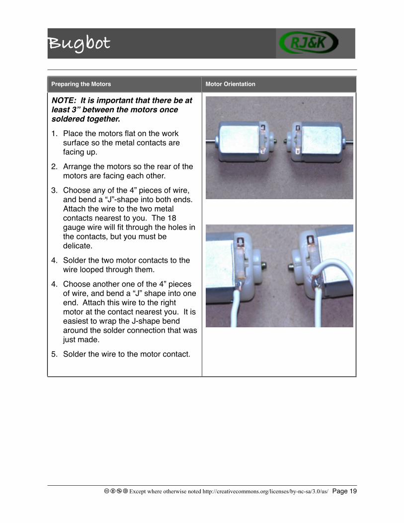
Preparing the Motors Motor Orientation
NOTE: It is important that there be at least 3” between the motors once soldered together.
1. Place the motors flat on the work surface so the metal contacts are facing up.
2. Arrange the motors so the rear of the motors are facing each other.
3. Choose any of the 4” pieces of wire, and bend a “J”-shape into both ends. Attach the wire to the two metal contacts nearest to you. The 18 gauge wire will fit through the holes in the contacts, but you must be delicate.
4. Solder the two motor contacts to the wire looped through them.
4. Choose another one of the 4” pieces of wire, and bend a “J” shape into one end. Attach this wire to the right motor at the contact nearest you. It is easiest to wrap the J-shape bend around the solder connection that was just made.
5. Solder the wire to the motor contact.
Bugbot Assemblies
Bugbot
c b n a Except where otherwise noted http://creativecommons.org/licenses/by-nc-sa/3.0/us/ Page 20
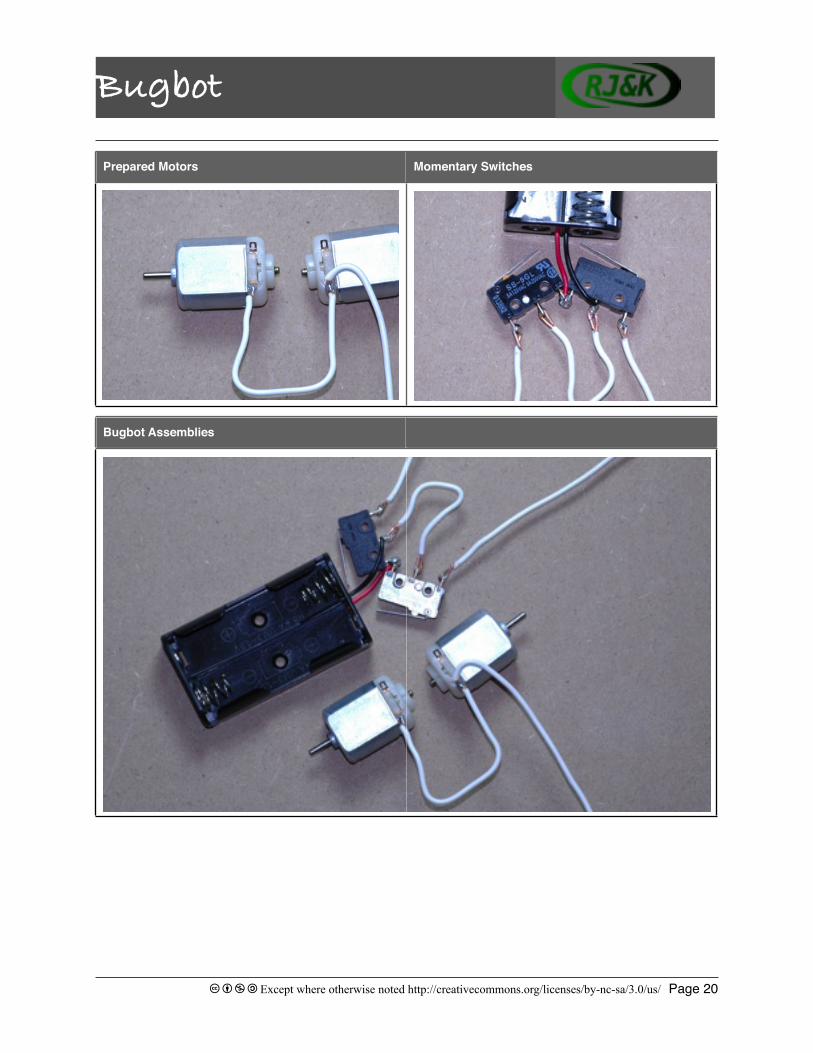
Prepared Motors Momentary Switches
Bugbot Assemblies

Bugbotʼs Body
Bugbot
c b n a Except where otherwise noted http://creativecommons.org/licenses/by-nc-sa/3.0/us/ Page 21
Building Bugbotʼs Body Wire Attachment
In this step, we will assemble Bugbotʼs body. Bugbot has two main body parts, the chassis and the motor carrier. The chassis is the battery box, and the motor carrier is the strip of Aluminum. Weʼll add Bugbotʼs tail later.
1. Place a mark down the middle of the Aluminum strip and line this mark up with the middle line of the battery box. The Aluminum should make a T with the battery box.
2. Mark the edges of the battery box on the Aluminum.
3. Bend the Aluminum at the marks to create a wide “U” shape.
4. Place a bead of hot glue in the center of the battery box about 1” away from the edge with the red and black wires.
5. Press the Aluminum onto the glue, positioning the strips so that the ends can be wrapped around the battery box.
6. After the hot glue cools, adjust the angle of the motor carrier bends until you are satisfied with Bugbotʼs height. Remember, you will be gluing the motors onto the carrier as well.
7. Use the remaining 4” piece of wire and bend a “J” shape into one end.
8. Hook the wire around the spring in the battery box on the end away from the red and black leads.
9. Solder this wire to the spring.
NOTE: Be careful not to heat up the spring too much, it may melt the battery box.
In this step, we will assemble Bugbotʼs body. Bugbot has two main body parts, the chassis and the motor carrier. The chassis is the battery box, and the motor carrier is the strip of Aluminum. Weʼll add Bugbotʼs tail later.
1. Place a mark down the middle of the Aluminum strip and line this mark up with the middle line of the battery box. The Aluminum should make a T with the battery box.
2. Mark the edges of the battery box on the Aluminum.
3. Bend the Aluminum at the marks to create a wide “U” shape.
4. Place a bead of hot glue in the center of the battery box about 1” away from the edge with the red and black wires.
5. Press the Aluminum onto the glue, positioning the strips so that the ends can be wrapped around the battery box.
6. After the hot glue cools, adjust the angle of the motor carrier bends until you are satisfied with Bugbotʼs height. Remember, you will be gluing the motors onto the carrier as well.
7. Use the remaining 4” piece of wire and bend a “J” shape into one end.
8. Hook the wire around the spring in the battery box on the end away from the red and black leads.
9. Solder this wire to the spring.
Assembled Body
In this step, we will assemble Bugbotʼs body. Bugbot has two main body parts, the chassis and the motor carrier. The chassis is the battery box, and the motor carrier is the strip of Aluminum. Weʼll add Bugbotʼs tail later.
1. Place a mark down the middle of the Aluminum strip and line this mark up with the middle line of the battery box. The Aluminum should make a T with the battery box.
2. Mark the edges of the battery box on the Aluminum.
3. Bend the Aluminum at the marks to create a wide “U” shape.
4. Place a bead of hot glue in the center of the battery box about 1” away from the edge with the red and black wires.
5. Press the Aluminum onto the glue, positioning the strips so that the ends can be wrapped around the battery box.
6. After the hot glue cools, adjust the angle of the motor carrier bends until you are satisfied with Bugbotʼs height. Remember, you will be gluing the motors onto the carrier as well.
7. Use the remaining 4” piece of wire and bend a “J” shape into one end.
8. Hook the wire around the spring in the battery box on the end away from the red and black leads.
9. Solder this wire to the spring.
Interesting fact: “Procter & Gamble chemical and packaging engineer, Paul Cope invented thermoplastic glue around 1940...” Source: about.com

Bugbotʼs TailSwitches
Bugbot
c b n a Except where otherwise noted http://creativecommons.org/licenses/by-nc-sa/3.0/us/ Page 22
Attaching the Switches Switches Mounted on Bugbot
The momentary switches are going to be mounted on the top front of Bugbot with the switch levers facing front.
1. Rotate the momentary switches so the red and black leads from the battery box come over the top of the switches and the switch levers are facing the front of the robot.
2. Place a bead of hot glue on the bottom of each switch.
3. Press the momentary switches onto the top of the battery box on the side nearest the red and black wires.
4. Next put a bead of glue on the bottom of the slide switch.
5. Press the slide switch onto the top of the battery box on the end furthest from the red and black wires so the slide faces the rear of Bugbot
Building Bugbotʼs Tail Bugbotʼs Tail
1. Straighten one of the paper clips.
2. Slide the bead to the middle of the paper clip.
3. Bend the paper clip around the bead so the paper clip forms a “U” shape around the bead.
4. This is Bugbotʼs tail. You may want to try different shapes to make sure the bead can still roll, while the bead stays at the bottom of the tail.
Attaching the motorsAttaching the tail
Bugbot
c b n a Except where otherwise noted http://creativecommons.org/licenses/by-nc-sa/3.0/us/ Page 23
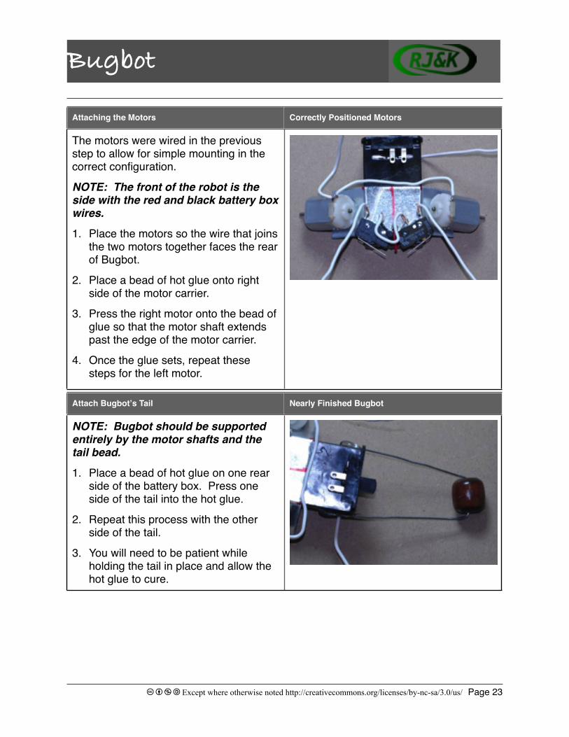
Attach Bugbotʼs Tail Nearly Finished Bugbot
NOTE: Bugbot should be supported entirely by the motor shafts and the tail bead.
1. Place a bead of hot glue on one rear side of the battery box. Press one side of the tail into the hot glue.
2. Repeat this process with the other side of the tail.
3. You will need to be patient while holding the tail in place and allow the hot glue to cure.
Attaching the Motors Correctly Positioned Motors
The motors were wired in the previous step to allow for simple mounting in the correct configuration.
NOTE: The front of the robot is the side with the red and black battery box wires.
1. Place the motors so the wire that joins the two motors together faces the rear of Bugbot.
2. Place a bead of hot glue onto right side of the motor carrier.
3. Press the right motor onto the bead of glue so that the motor shaft extends past the edge of the motor carrier.
4. Once the glue sets, repeat these steps for the left motor.

Final Electrical Connections
Bugbot
c b n a Except where otherwise noted http://creativecommons.org/licenses/by-nc-sa/3.0/us/ Page 24
Final Electrical Connections Motor Wires
There are a few more electrical connections that must be made to complete Bugbotʼs “nervous system.”
NOTE: Be careful not to overheat the switch tabs. Overheating can cause the switch to melt.
1. Following the same procedures for soldering as before, begin by soldering the loose wire from the motor to the slide switch.
2. Solder the wire connected to the battery box spring to the other slide switch terminal.
3. Next, solder the loose wire from the right momentary switch to the free terminal on the right motor.
4. Repeat step three with the left momentary switch and the left motor.
Bugbot is nearly complete! All that is left is to give Bugbot its antennae and some traction.
Switch Wires
There are a few more electrical connections that must be made to complete Bugbotʼs “nervous system.”
NOTE: Be careful not to overheat the switch tabs. Overheating can cause the switch to melt.
1. Following the same procedures for soldering as before, begin by soldering the loose wire from the motor to the slide switch.
2. Solder the wire connected to the battery box spring to the other slide switch terminal.
3. Next, solder the loose wire from the right momentary switch to the free terminal on the right motor.
4. Repeat step three with the left momentary switch and the left motor.
Bugbot is nearly complete! All that is left is to give Bugbot its antennae and some traction.

Adding some frictionAntennae
Bugbot
c b n a Except where otherwise noted http://creativecommons.org/licenses/by-nc-sa/3.0/us/ Page 25
Antennae Antennae and Shrink Tubing
The antennae consist of the last two paper clips and the last two pieces of shrink tubing.
NOTE: Be careful not to heat the switch body while you are shrinking the tubing.
1. Cut the capped ends off of both pieces of shrink tubing.
2. Straighten both of the paper clips that are left.
3. Slide one piece of shrink tubing over each paper clip.
4. Position the end of one paper clip against the lever of one of the momentary switches.
5. Slide the shrink tubing down the paper clip and over the lever.
Adding Some Friction Bugbotʼs tires
Bugbot needs some friction between the motor shafts and the ground. We gain the needed friction by adding shrink tubing to each motor shaft.
1. Cut two pieces of shrink tubing so that they are not too long for the motor shafts to seat neatly inside the tubing.
2. Slide the open end of one of the pieces of shrink tubing onto one of the motor shafts.
3. Using a safety lighter or heat gun, heat the shrink tubing until it shrinks onto the motor shaft.
4. Repeat this process with the other motor shaft.

Bugbot
c b n a Except where otherwise noted http://creativecommons.org/licenses/by-nc-sa/3.0/us/ Page 26
Antennae Continued. Completed Bugbot
6. With the lighter, or heat gun, heat the shrink tubing until the tubing shrinks and holds the paper clip in place.
7. Repeat with the other switch.
8. Once the antennae are attached to the momentary switches, put a bead of hot glue on each antenna where the heat tubing ends. Be careful not to get hot glue under the lever.

Helping Hands (Optional)ToolsParts
Helping Hands
c b n a Except where otherwise noted http://creativecommons.org/licenses/by-nc-sa/3.0/us/ Page 27
Name:
Partnerʼs Name:
“If I lived back in the wild west days, instead of carrying a six-gun in my holster, I'd carry a soldering iron.”
--Jack Handy
Description: Helping Hands
When soldering small components, it is often very helpful to have an extra set of hands. While it is not always possible to work with another person, several devices have been created to assist with holding components during soldering. A very common, and easy to build, device called the Helping Hands is one such device.
Tools and Parts Tools
While very few tools and parts are required to build the helping hands, it is always a good idea to start a project by collecting the things you need at the beginning.
Tools:
1. #2 Philips Screw Driver
2. Crimpers
3. Pliers
Parts:
1. 2 wood screws
2. Block of soft wood
3. 2 large washers
4. 2 pieces of stiff wire
5. 2 alligator clips
Parts
While very few tools and parts are required to build the helping hands, it is always a good idea to start a project by collecting the things you need at the beginning.
Tools:
1. #2 Philips Screw Driver
2. Crimpers
3. Pliers
Parts:
1. 2 wood screws
2. Block of soft wood
3. 2 large washers
4. 2 pieces of stiff wire
5. 2 alligator clips

Assembly
Helping Hands
c b n a Except where otherwise noted http://creativecommons.org/licenses/by-nc-sa/3.0/us/ Page 28
Assembly Crimping
1. Crimp one alligator clip on one end of each “arm.”
2. Bend the other end of each arm into a small U-shape.
3. Using the wood screw, and the large washer, screw the hook end of one arm into a corner of the wood block.
4. Repeat this step for the other arm.
The Helping Hands is an indispensable tool when you are soldering. Not only will it keep your fingers away from the hot tools you will be using, it will hold your parts for you so that your solder joints come out exactly the way you want them.
Preparing the base of the arms
1. Crimp one alligator clip on one end of each “arm.”
2. Bend the other end of each arm into a small U-shape.
3. Using the wood screw, and the large washer, screw the hook end of one arm into a corner of the wood block.
4. Repeat this step for the other arm.
The Helping Hands is an indispensable tool when you are soldering. Not only will it keep your fingers away from the hot tools you will be using, it will hold your parts for you so that your solder joints come out exactly the way you want them.
Completed Helping Hands
1. Crimp one alligator clip on one end of each “arm.”
2. Bend the other end of each arm into a small U-shape.
3. Using the wood screw, and the large washer, screw the hook end of one arm into a corner of the wood block.
4. Repeat this step for the other arm.
The Helping Hands is an indispensable tool when you are soldering. Not only will it keep your fingers away from the hot tools you will be using, it will hold your parts for you so that your solder joints come out exactly the way you want them.