BT TM-15 Manual - PAINT-SUPPLY.net
24
B T P A I N T B A L L . C O M BT_TM-15_Manual.qxp 6/17/09 5:23 PM Page B
Transcript of BT TM-15 Manual - PAINT-SUPPLY.net

B T P A I N T B A L L . C O M
BT_TM-15_Manual.qxp 6/17/09 5:23 PM Page B

O W N E R ’ S M A N U A L
B T P A I N T B A L L . C O M
BT_TM-15_Manual.qxp 6/17/09 5:23 PM Page C

B T P A I N T B A L L . C O M
CONTENTS Page
1. Rules for Safe Marker Handling 1
2. Introduction and Specifications 1
3. Battery Replacement and Life Indicator 1
4. Compressed Air/Nitrogen Supply 2
5. Basic Operation 2
6. Firing the TM-15 4
7. Break Beam Eyes Operation 4
8. Unloading the TM-15 5
9. Regulator and Velocity Adjustments 5
10. Programming 6
11. Setting Functions 7
12. Trigger Adjustments 9
13. General Maintenance 10
14. Assembly/Disassembly Instructions 11
15. Storage and Transportation 14
16. Troubleshooting Guide 14
17. Diagrams and Parts List 17
WARRANTY (Inside Back Cover)
NEITHER BT PAINTBALL DESIGNS, INC. NOR ANY OF ITS PRODUCTS ARE AFFILIATED WITH TIPPMANN SPORTS, LLC.
For manuals and warranty details, go to: paintballsolutions.com
For manuals in other languages, (where appli-cable), go to:paintballsolutions.com
©2009 BT Paintball Designs, Inc. The BT Shield,“Battle Tested” and “TM-15” are trademarks ofBT Paintball Designs, Inc. All rights reserved.
BT_TM-15_Manual.qxp 6/17/09 5:23 PM Page D

B T P A I N T B A L L . C O M
TM-15 Limited Lifetime Warranty
LIMITED LIFETIME WARRANTY INFORMATION (ORIGINAL PURCHASERECEIPT REQUIRED)KEE Action Sports (“KEE”) warrants that this product is free from defects in materials and work-manship for as long as it is owned by the original purchaser, subject to the terms and condi-tions set forth below. KEE Action Sports will repair or replace with the same or equivalentmodel, without charge, any of its products that have failed in normal use because of a defectin material or workmanship.
KEE Action Sports is dedicated to providing you with products of the highest quality and theindustry’s best product support available for satisfactory play.
Purchaser should register product to activate warranty. Register your product by:1. Online at www.paintballsolutions.com2. Complete the product registration card (if applicable) and mail along with a copy of yourreceipt to Paintball Solutions, 570 Mantua Blvd., Sewell, NJ 08080.
WHAT THIS WARRANTY DOES NOT COVERThis warranty does not cover problems resulting from abuse, the unauthorized modification oralteration of our product, problems resulting from the addition of aftermarket products andscratches or minor superficial imperfections. Due to the nature of paintball products it is impor-tant that the product be maintained by the user as indicated in the product manual to remainin good operating condition. Your Limited Lifetime Warranty will be void if you fail to maintainthe product as recommended in the product instruction manual. In addition, certain parts ofa product may be subject to wear through regular usage. Replacement and repair of suchparts is the responsibility of the user throughout the life of the product. These parts are not cov-ered under the Limited Warranty. Examples of this type of part include (but are not limited to)goggle lens, straps, o-ring seals, cup seals, springs, ball detentes, batteries, hoses, drive belts,gears and any part of a product subject to continuous impact from paintballs. Hydrotesting ofair cylinders is not covered under this warranty.
The Limited Lifetime Warranty also does not cover incidental or consequential damages. Thiswarranty is the sole written warranty on KEE’s product and limits any implied warranty to theperiod that the product is owned by the original purchaser.Some states, provinces and nations do not allow the limitation of implied warranties or of inci-dental or consequential damages, so the above limitations or exclusions may not apply to you.This warranty gives you specific legal rights and you may also have other rights which vary
from state to state, province to province, nation to nation.
If you should encounter any problems with your product and you have added aftermarketparts on your product, please test it with the original stock parts before sending it in. Alwaysunload and remove air supply before shipping markers. Do not ship your air supply tank if itis not completely empty. Shipping a pressurized air supply tank is unsafe and unlawful. Removeall batteries from products prior to shipping.
This Limited Warranty gives you specific legal rights, and you may also have other rights which varyfrom state to state. Some states do not allow the exclusion of incidental or consequential damages.
For warranty parts, service or information contact: Paintball Solutions • www.paintballsolutions.comE-mail: [email protected] • Phone: 1-800-220-3222
May be covered by: 5,881,707; 5,967,133; 6,035,843; 6,474,326; 6,637,421 and 7,100,593,marked under license; 6,601,780; 6,925,997; 6,161,573; 6,057,750 and EPC patented.
PAINTBALL GUNS AND PAINTBALL GUN ACCESSORIES ARE NOT TOYS!- Careless use or misuse may result in serious bodily injury or death!- Eye protection designed for paintball must be worn by the user and all persons within range.- Not for sale to persons under 18 years of age.- Must be 18 years of age or older to operate or handle any paintball gun and paintball gunaccessories without adult of parental supervision.
- Read and understand all cautions, warnings, and operating manuals before using any paint-ball gun or paintball gun accessory.
- Do not aim paintball gun at eyes or head of people or at animals.- Paintball guns are to be used with .68 caliber Paintballs Only.- To prevent fire or shock hazard, do not expose unit to rain or moisture.- To prevent fire or shock hazard, do not immerse unit in liquids.- To prevent fire or shock hazard, do not disassemble any electronic paintball device.- Please conform to all local or state regulations with regard to battery disposal.- Use Common Sense and have fun.
TM-15 Instruction Manual Version 1.0 05/09.
BT_TM-15_Manual.qxp 6/17/09 5:23 PM Page E

B T P A I N T B A L L . C O M 1
1. Rules for Safe Marker Handling IMPORTANT: Never carry your TM-15 uncased when not on a playingfield. The non-playing public and law enforcement personnel may not beable to distinguish between a paintball marker and firearm. For your ownsafety and to protect the image of the sport, always carry your TM-15 ina suitable marker case or in the box it came in.
• Treat every marker as if it were loaded.• Never look down the barrel of a paintball marker. • Keep your finger OFF the trigger until ready to shoot.• Never point the marker at anything you don’t wish to shoot.• Keep the marker on “safe” until ready to shoot.• Keep the barrel blocking device in/on the marker’s barrel when not shooting. • Always remove paintballs and air source before disassembly. • After removing air source, point marker in safe direction and discharge
until marker is degassed.• Store the marker unloaded and degassed in a secure place.• Follow warnings listed on the air source for handling and storage. • Do not shoot at fragile objects such as windows. • Every person within range must wear eye, face, and ear protection designed
specifically to stop paintballs and meeting ASTM standard F1776. • Always measure your marker’s velocity before playing paintball and
never shoot at velocities in excess of 91.44 meters (300 feet-per-second).
READ OWNERS MANUAL BEFORE USING.
2. Introduction and SpecificationsCongratulations on your selection of the TM-15 paintball marker. The TM-15 is made to provide you with many years of reliable performance. We arehonored that you have chosen the TM-15 as your marker of choice andhope you enjoy using this high quality product.
The patented Valve design, Slip Stream™ Solenoid, Hall Effect SensorTrigger, and Four Position Selector Switch set new standards for marker tech-
nology. The TM-15 is precision engineered from magnesium alloy, aircraft-grade aluminum, and composite materials. We expect you to play hard andplay frequently and the TM-15 was built with this in mind.
The TM-15 operates on low pressure. The main operating pressure is180–200 PSI. The pressure can be nominally adjusted and monitored visuallyvia the gauge on the bottomline regulator. There is no secondary regulatorto worry about.
TTMM--1155 SSppeecciiffiiccaattiioonnss Model- TM-15Barrel- 14" Ported BarrelCaliber- .68Action- Semi Auto, PSP Burst, and NXL Full AutoAir source- Compressed Air Battery- One 9-Volt (Alkaline Only)Cycle Rate- Up to 20 BPSShell Material- Magnesium AlloyAccuracy Range- 150ft +
IInncclluuddeedd wwiitthh yyoouurr TTMM--1155- 14" Barrel (.691 bore)- Allen Wrenches- Spare Parts Kit- Barrel Blocking Device- One 9-Volt Battery - Manual - One BT Rip-Clip™Adapter & Adapter Screw Kit, for use with the TM Rip-Clip™ only. (TM Rip-Clip™ not included)
3. Battery Replacement and Life IndicatorThe TM-15 requires a single 9-volt alkaline battery as the electronic powersource. The use of long life batteries is recommended. The battery is installedby removing the magazine and inserting a 9-Volt battery into the magazine.
BT_TM-15_Manual.qxp 6/17/09 5:23 PM Page 1

B T P A I N T B A L L . C O M2
To remove the magazine, press in the magazine release button, which islocated on the right side of the TM-15. While pressing the release button,pull the magazine down and out of the body and then insert a 9-volt bat-tery following the polarity markings on the side of the magazine. (Fig. 1.1)
The TM-15 also has a battery lifeindicator. When in a firing mode(F1, F2, and F3), if the LED flash-es green then the battery isgood, if the LED is orange thebattery is fairly depleted and youshould change batteries soon, orif the LED is red then the batteryshould be replaced immediately.
Note: Some rechargeable batteries might be too large for the TM-15magazine battery compartment. If they do not fit, please do not forcethem into the magazine.
4. Compressed Air/Nitrogen SupplyThe TM-15 is designed to work with compressed air/nitrogen only. Do notuse CO2, as it will damage your TM-15.
Consult the Dealer where you purchased your TM-15, or a recognized andcompetent air smith, for instruction in the safe handling of compressed-aircylinders before purchasing or connecting one to your TM-15.
The TM-15 utilizes a fully functional regulator at the bottom of the gripframe that doubles as an ASA (Air Source Adapter) or Receiver for a stan-dard threaded pre-set output compressed air system. It is strongly recom-mended that a very high-flow “low-pressure” (350–450 psi) fixed-output sys-tem is utilized as an air source for your TM-15. Using a “high-pressure” out-put compressed air tank is acceptable. If you are using an adjustable out-
put regulator system, the output pressure should be between 400–500 psi.
Before pressurizing your TM-15:• Check to make sure that you and anyone within range are wearing eye
protection designed specifically for paintball. • Double check that all screws are tightened and no parts are loose before
installing your tank. • Ensure you have a barrel plug, barrel cover, or other specifically designed
barrel-blocking device in place.• Make sure there are no paintballs in the marker. • The Power should be OFF and the Selector switch should be set to the
Safety position.
Air can now be applied; the marker will become pressurized.
Notes: • Remember compressed air or nitrogen systems can be extremely dan-
gerous if misused or improperly handled. Use only cylinders meetingD.O.T. or regionally defined specifications.
• Never disassemble your tank or tank regulator. Only a qualified andtrained technician should perform work on your tank and tank regulator.
• Never add any lubricants or greases into the fill adapter on your tankregulator or into the TM-15 regulator.
5. Basic Operation Safety and safe marker handling are the most important aspects of paint-ball sports. Please practice each of the following steps with an unloadedmarker before attempting to charge your marker with compressed airand paintballs.
• Do not install compressed air or load paintballs into your TM-15 until youfeel completely confident with your ability to handle your TM-15 safely.
Fig 1.1Fig 1.1
BT_TM-15_Manual.qxp 6/17/09 5:23 PM Page 2

B T P A I N T B A L L . C O M 3
• Keep your finger out of the trigger guard and away from the trigger;point the muzzle of the marker in a safe direction at all times. Keep themarker turned OFF when not in use. The TM-15 uses a power switchand a selector switch for its safety devices.
• Always keep your TM-15 pointed in a safe direction. Always use a barrelplug or barrel blocking device. Always use paintball specific eye protec-tion meeting or exceeding ASTM standards in any areas where paintballmarkers may be discharged.
• Remember that the ultimate safety device is you, the operator.
Feed Elbow InstallationSeat the feed elbow ontothe narrow section of thetop picatinny rail: about 1"forward of the feed hole onthe right side of the marker (Fig. 1.2). Then pushand hold in the latch button while sliding the feed elbow toward the rearof the marker (Fig. 1.3). Just before the feed elbow covers the feed holein the right side of the marker, release the latch button and continue slid-ing the feed elbow until the latch locks into the rail slot. When done cor-rectly, the feed elbow will now be unable to slide forward or backwardwithout holding in the latch button, and the feed hole in the right sideshell will not be visible from the sides of the feed elbow.
Barrel InstallationMake sure marker is degassed, hopper removed, no paintballs in the feedelbow or breech, and the TM-15 is turned off.
• While pointing marker in a safe direction, place the threaded end of thebarrel into the front opening of the marker body.
• Turn the barrel clockwise until it stops (do not over tighten). • Install a barrel blocking device. This can be a barrel plug or other such
device that prevents the accidental discharge of paintballs.
Switching on your TM-15Warning: Before switching on your TM-15, make sure it is pointed in a safedirection. Always use a barrel plug or barrel blocking device. Rememberthat the ultimate safety device is you, the operator.
To switch the TM-15 on, set the selector switch to the (S) safety position.The TM-15 will not turn on unless the selector is in the safety position.Locate the power button on the left side of the marker. Push and hold thepower button for 2 seconds and the LED light will turn green and then tored. Release the button and the LED will remain red.
The TM-15 will now be on and in the (S) safety position. To make the TM-15 live,move the selector switch to the F1, F2, or F3 positions. Do not move the selec-tor switch to a firing position until you are ready to safely use the marker.
Switching OFF your TM-15Move the Selector Switch to the (S) safety position, push and hold thepower button for 2 seconds, and the LED will turn from red to green.Release the power button and the TM-15 will switch off.
Selector SwitchThe TM-15 comes equipped with a four-position selector switch which comesfactory set in the recreational firing mode setting. Move the selector from posi-tion (S) safety, to positions (F1, F2, and F3) to change into a firing mode (Fig 1.4).
Selector PositionsSafety ---------------------------------Semi-Auto ------------------------PSP Ramping -------------------NXL Full Auto ------------------
Automatic OFF featureThe TM-15 also has an “Automatic OFF” feature. If you accidentally leaveyour TM-15 powered up, it will shut itself off after approximately 1 hourof inactivity.
Fig 1.3Fig 1.2
Fig 1.4
BT_TM-15_Manual.qxp 6/17/09 5:23 PM Page 3
B T P A I N T B A L L . C O M4
Eye Function The TM-15 board is pre-programmed to activate the eye system eachtime the marker is powered up. See Section 7 (Break Beam Eyes Oper-ation) for more details.
Installing a Loader and PaintballsThe TM-15 comes equipped to accept 1.03" (outer dimension) standard-gravity feed loaders as well as most agitating and force-feed loaders. Fitthe loader directly into the feed elbow. It might be necessary to adjust thefeed elbow clamping screw to your loader.
The TM-15 uses .68 caliber, water-soluble paintballs, readily available atpaintball pro-shops, commercial playing fields, and many sporting goodsstores. The paintballs are fed from the loader through the feed elbow andinto the breech of the marker.
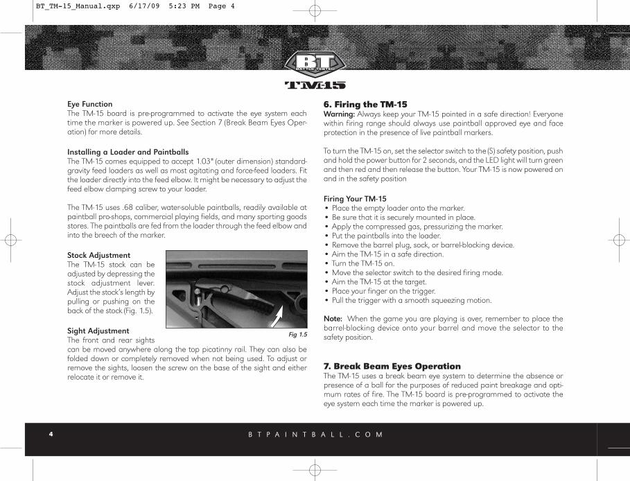
Stock AdjustmentThe TM-15 stock can beadjusted by depressing thestock adjustment lever.Adjust the stock’s length bypulling or pushing on theback of the stock (Fig. 1.5).
Sight AdjustmentThe front and rear sightscan be moved anywhere along the top picatinny rail. They can also befolded down or completely removed when not being used. To adjust orremove the sights, loosen the screw on the base of the sight and eitherrelocate it or remove it.
6. Firing the TM-15Warning: Always keep your TM-15 pointed in a safe direction! Everyonewithin firing range should always use paintball approved eye and faceprotection in the presence of live paintball markers.
To turn the TM-15 on, set the selector switch to the (S) safety position, pushand hold the power button for 2 seconds, and the LED light will turn greenand then red and then release the button. Your TM-15 is now powered onand in the safety position
Firing Your TM-15• Place the empty loader onto the marker. • Be sure that it is securely mounted in place. • Apply the compressed gas, pressurizing the marker. • Put the paintballs into the loader. • Remove the barrel plug, sock, or barrel-blocking device. • Aim the TM-15 in a safe direction. • Turn the TM-15 on.• Move the selector switch to the desired firing mode. • Aim the TM-15 at the target. • Place your finger on the trigger. • Pull the trigger with a smooth squeezing motion.
Note: When the game you are playing is over, remember to place thebarrel-blocking device onto your barrel and move the selector to the safety position.
7. Break Beam Eyes OperationThe TM-15 uses a break beam eye system to determine the absence orpresence of a ball for the purposes of reduced paint breakage and opti-mum rates of fire. The TM-15 board is pre-programmed to activate theeye system each time the marker is powered up.
Fig 1.5
BT_TM-15_Manual.qxp 6/17/09 5:23 PM Page 4

B T P A I N T B A L L . C O M 5
To turn the eyes off, ensure that there are no paintballs in the markersbreech or feed elbow and make sure the marker is switched off. Whilepulling and holding the trigger, turn the marker on. When the selector isswitched to a firing mode, a quick double blinking green LED will indicatethat the eye system has been deactivated. To turn the eyes back on, simply press the power button one time quickly.
Notes:• When the eyes are on, a slow consistent single-flashing green LED
indicates that no ball is in the breech and a rapid flashing green LEDindicates that there is a ball in the breech.
• For optimal performance of the TM-15 eyes, keep the inside of the TM-15 breech clean and clear of broken paint, paint residue, or otherdebris.
• Although the eyes can be cleaned via cleaning the breech of the TM-15marker, if the eyes need to be accessed, please follow the steps outlinedin the Disassembly/Assembly section of this manual.
8. Unloading the TM-15Warning: Always keep your TM-15 pointed in a safe direction and alwayskeep your protective eye, face, and ear wear on until marker is complete-ly unloaded and safe.
• Be sure your finger is away from the trigger area.• Place the barrel plug, sock, or barrel-blocking device into the end of the
barrel.• Move the selector switch to the (S) safety position.• Turn the TM-15 off by pressing and holding the power button. The LED
will change from red to green, once it changes to green, release thebutton. Observe the light to make sure it is no longer lit.
• Remove your pressurized gas source by slowly and carefullyunscrewing it.
• If you are using an electronic loader make sure loader is completelyturned off.
• Slightly tilt the marker so that the loader is lower than the body.• Remove the loader by releasing the clamp and spinning it in a
clockwise direction and gently pulling it.• Read the pressure gauge and make sure the pressure reads 0 psi.• Do not look down the barrel but look down the feed neck to make sure
there are no paintballs in the breech.• Remove the barrel from the marker.• Make sure there are no more paintballs remaining in the barrel.
9. Regulator and Velocity AdjustmentThe TM-15 utilizes a Bottom-line regulator that doubles as an ASAAdapter/Receiver for a standard threaded pre-set output compressed airsystems or remote hose. This unique regulator system channels airthrough the air transfer tube, eliminating the need for external macro lineand fittings. The TM-15 bottom-line regulator controls the amount of airpressure going from your compressed air system into the marker.
The TM-15 regulator should be factory pre-set at about 200 psi, as this isthe best operating pressure for proper marker operation. However, if overtime you do need to adjust the pressure, use the Regulator Adjuster Screwon the front of your TM-15 bottom-line regulator.
Regulator AdjustmentNote: Do not use this to adjust the velocity of the marker.
If adjustments are needed, use a 3/16"Allen wrench and insert it into the regu-lator adjustment screw. This is located inthe front of the regulator (Fig. 1.6).
To Increase Output Pressure- Turn the reg-ulator’s adjustment screw clockwise. To Decrease Output Pressure- Turn theregulator’s adjustment screw counter-clockwise.
Fig 1.6
BT_TM-15_Manual.qxp 6/17/09 5:23 PM Page 5

B T P A I N T B A L L . C O M6
Notes: • Always watch the gauge as you are adjusting the pressure. • The bottomline regulator should not be disassembled.• Never set the regulator above 200 psi.
Adjusting Velocity- At the back of the TM-15 internal body is the boltguide cap. The holes in the bolt guide cap serve as your velocity adjuster.Confirm that the pressure on your TM-15 bottom-line regulator is at 200PSI.
You can access the velocity adjuster by sliding the velocity adjustmentcover forward and inserting a 7/64" Allen wrench into the bolt guide capthru the bottom of the marker. Then you can increase or decrease thevelocity on your TM-15 by tightening or loosening the bolt guide cap, usingthe included 7/64" inch Allen wrench.
To Increase Velocity- Unscrew or loosen thevelocity adjustment screw by turning itcounter clockwise. Rotate the velocityadjustment screw in small increments, stop-ping between slight turns to test velocity,until desired velocity is achieved. Do notback the adjuster out too far. Stop if youhear an air leak, and adjust back in a 1/4turn (Fig. 1.7). A paintball specific radar chronograph should be used toaccurately measure your velocity.
To Decrease Velocity- Tighten or screw-in the velocity adjustment screwby turning it clockwise. Rotate the velocity adjustment screw clockwise insmall increments (1/4 turn or less), stopping between slight turns to testvelocity, until desired velocity is achieved. A paintball specific radarchronograph should be used to accurately measure your velocity.
Notes:•This marker was designed with safety and safety standards in mind. If
you attempt to shoot paintballs at a higher velocity than establishedsafety standards, the marker may not function properly.
• This marker is not designed to shoot above the safety limits establishedby Industry Standards, but under certain conditions it may. It is there-fore important to check the velocity before using your TM-15.
• The velocity is not adjusted by inserting the Allen wrench into the velocityadjuster and rotating the Allen wrench, but by using the Allen wrench asa handle to rotate the velocity adjuster.
10. Programming Note: In this section, you will see the phrase "Cycle the Selector Switch".To cycle the selector switch, move the selector switch from the (S) positionto the (F3) position and then back to the (S) position.
Tournament Lock On/OffThe TM-15 comes with a tournament lock which will lock your marker intothe firing mode currently selected. The Tournament lock button isaccessed thru a small hole just in front of the trigger. The TM-15 must beturned off to change the tournament lock setting.
Carefully insert the long side of the 3/32" Allen wrench into the hole on thetrigger guard and then into the hole on thebody and then gently press the tournament lockbutton to show the current status of the tourna-ment lock (Fig. 1.8).
• If the LED blinks green, the tournament lockis on.
• If the LED blinks red, the tournament lock isoff.
Fig 1.7
Fig 1.8
BT_TM-15_Manual.qxp 6/17/09 5:23 PM Page 6

To change the tournament lock, press the button once to display the cur-rent status, then press it again within 1 second and the LED will blink thenew status.
Note: The tournament lock button is part of the markers circuit board.Only use light pressure when pressing the button.
To Enter Programming Mode- The TM-15 must be OFF and the tourna-ment lock must be off to begin managing the functions. While the TM-15is off, with the selector switch in the safety (S) position, press and hold thepower button, cycle the selector switch, then release the power button toenter programming mode. If done correctly the LED will change to a solidred, which is the firing mode function.
Once in programming mode, with selector switch in the (S) position, eachtime the power button is pushed you will cycle to the next Function andthe LED will change to a specific color per the descriptions below. Function’s current value- To view a function’s current value, advance tothe function you wish to check using the power button. Then simply pulland release the trigger quickly to view its current value by observing thenumber of flashes.
Changing a Function’s Value- Once you have selected the function you wish tochange, move the selector switch to the (F1) position to increase the value or tothe (F2) position to decrease the value. Each time the trigger is pulled it will increase
or decrease the function’s value by one. If the selector switch is in the (F3) position,a single trigger pull will return a function value to its default setting. Once a func-tion’s value is changed, move the selector switch to the the (S) safety position.To check the function’s new value, simply pull and release the trigger once whilethe selector is in the safety (S) position and the LED will flash the new value. At thispoint, you can select a different function to change or exit programming mode.
Exiting Programming Mode- push and hold the power button, cycle theselector switch, and then release the power button.
11. Setting FunctionsFiring ModesFiring modes will be indicated by a solid red LED. The default firing modeis the recreational mode (value 5).
Note: Selector position (0) is used as a Safety in all Modes.Value 1: Semi-Auto – One shot per trigger pull.
Value 2: PSP – The TM-15 will operate in semi-auto mode for the first 3 safety shots; then if the user maintains at least one pull per a second, theTM-15 will fire “x” number of shots per pull and release of the trigger asdefined by function 6 (burst shots) at the rate of fire defined by function 2.No trigger pull within one second of the last pull will reset the mode and theuser must fire three more safety shots to continue burst shots.
B T P A I N T B A L L . C O M 7
Function LED Color Default Value Range1 Firing Mode Solid Red 5 1-52 ROF (rate-of-fire) Solid Green 11 1-253 Dwell Solid Orange 28 1-454 BIP (ball in place) Flashing Red 10 1-405 Ramping Point Flashing Green 4 3-96 Burst Shots Flashing Orange 3 3-9
Selector Switch Position in Programming Mode S Cycle to Next Function / Read a Current ValueF1 Increase a Function’s ValueF2 Decrease a Function’s ValueF3 Returns a Function to Factory Default
BT_TM-15_Manual.qxp 6/17/09 5:23 PM Page 7

B T P A I N T B A L L . C O M8
Value 3: Full-Auto/NXL – The TM-15 will operate in semi-auto mode forthe first 3 safety shots; then pull and hold trigger on the 4th shot, and theTM-15 will fire full-auto at the rate of fire value in function 2, which isdefaulted to 13 shots per second for this mode.
Value 4: Ramping/Millennium – The TM-15 will operate in semi-automode until player achieves the minimum trigger pull as defined by theramping point value in function 5, which is defaulted to 6 trigger pulls persecond for this mode. At that point, and as long as 6 trigger pulls per sec-ond are maintained, the TM-15 will ramp to the rate of fire value in func-tion 2, which is defaulted to 12 shots per second for this mode.
Value 5: Recreational Mode - Selector Switch Position (1) - StandardSelector Switch Position (F1) - Semi-automatic; see value 1.
Selector Switch Position (F2) – PSP; see value 2.
Selector Switch the (F3) Position - NXL full auto; see value 3.
Notes:• If you activate the tournament lock on your TM-15 while in recreation-
al mode, all three firing modes will still be active.• It is possible to raise or lower both the rate of fire and ramping point
values if rules change. • Selector the (S) position is used as a safety in all firing modes.
Max Rate of Fire (ROF)Max Rate of Fire (ROF) will be indicated by a solid green LED.The default Max ROF is 6 flashes (13 BPS).
Dwell SettingDwell Setting will be indicated by a solid orange LED.The Dwell setting determines how long the Slip Stream™ Solenoid isopen. The Dwell is defaulted at setting 28 and is adjustable from 1–45.
Note: If the Dwell Setting is adjusted too high or low, the TM-15 will notfunction correctly.
Flashes/ROF Flashes/ROF Flashes/ROF1 Flash = 8 BPS 2 Flash = 8.5 BPS3 Flash = 9 BPS4 Flash = 9.5 BPS5 Flash = 10 BPS6 Flash = 10.5 BPS7 Flash = 11 BPS8 Flash = 11.5 BPS9 Flash = 12 BPS
10 Flash = 12.5 BPS11 Flash = 13 BPS12 Flash = 13.5 BPS13 Flash = 14 BPS14 Flash = 14.5 BPS15 Flash = 15 BPS16 Flash = 15.5 BPS17 Flash = 16 BPS18 Flash = 16.5 BPS
19 Flash = 17 BPS20 Flash = 17.5 BPS21 Flash = 18 BPS22 Flash = 18.5 BPS23 Flash = 19 BPS24 Flash = 19.5 BPS25 Flash = 20 BPS
Firing ModesValue Selector Position Mode
F1 Semi-Auto1 F2 Semi-Auto
F3 Semi-AutoF1 PSP
2 F2 PSP F3 PSP F1 NXL Full-Auto
3 F2 NXL Full-AutoF3 NXL Full-AutoF1 Millennium Ramping
4 F2 Millennium RampingF3 Millennium RampingF1 Semi-Auto
5 F2 PSP F3 NXL Full-Auto
BT_TM-15_Manual.qxp 6/17/09 5:23 PM Page 8

B T P A I N T B A L L . C O M 9
Ball in Place Delay (BIP)Ball in Place Delay (BIP) will be indicated by a flashing red LED.The BIP is defaulted at 10 ms (each Flash = 1 millisecond). BIP isadjustable from 1–40 milliseconds.
Note: If you are not using a force-feed loader, it is recommended that youuse a higher BIP setting.
Ramping PointRamping Point will be indicated by a flashing green LED.
The default ramping point is 4 (4.5 BPS). Ramping Point is adjustable from4–9.5 BPS. Please see chart for corresponding flashes and BPS settings.
Burst ShotsBurst Shots will be indicated by a flashing orange LED.The Burst shot value is defaulted to 3 and is adjustable from (3–5).
Programming Example: If you are in the default recreational firing modeand want to go to semi-auto firing mode. Push and hold the power button,cycle the selector switch, then release the power button and the LED will bea solid red. Move the selector switch to position (F2) which will decrease thevalue and pull the trigger four times and then move the selector switch backto the (S) position. Pull the trigger while in the (S) position to check the
changed value. The LED will now flash 1 time, to show that the firing modehas been changed to semi-auto.
Factory Board ResetTo reset all the functions to the defaults, turn off your TM-15, then carefullyinsert the long side of the 3/32" Allen wrench into the tournament lockaccess hole and then gently press the button in for 5 seconds. Once anorange LED flashes to confirm the reset, release the button.
12. Trigger AdjustmentsThe TM-15 features a Hall Effect Sensor Trigger. There is no trigger switchto worry about, clog with paint, or break. The TM-15 trigger can be adjust-ed by the four set screws in the trigger.
When a trigger pull is recognized, the LED will quickly flash a dim Red foreach trigger pull. If no trigger pull is recognized, the LED flashes normal-ly based on the status of the eyes and battery power level. If the trigger isheld in, the dim red LED will stay illuminated.
Before making any trigger adjustments, de-gas the TM-15, make sure thegauge reads 0 psi, then switch ON the TM-15 with eyes turned off to easily monitor the current activation point.
You will notice four (4) set screws in your trigger (Fig. 1.9). These can be adjusted with a 1/16" Allen wrench. Make small adjustments and check thatthe trigger is activating the solenoid.
• The first (1) set screw adjusts thetrigger activation point. For bestresults, the activation point shouldbe set right in the middle of thetotal trigger movement from frontto back.
6 Flashes = 3 BPS7 Flashes = 3.5 BPS8 Flashes = 4 BPS9 Flashes = 4.5 BPS10 Flashes = 5 BPS11 Flashes = 5.5 BPS12 Flashes = 6 BPS
13 Flashes = 6.5BPS14 Flashes = 7 BPS15 Flashes = 7.5 BPS16 Flashes = 8 BPS17 Flashes = 8.5 BPS18 Flashes = 9 BPS
Ramping PointFlashes/PTR (Pulls to Ramp)
1 2 3 4
Fig 1.9
BT_TM-15_Manual.qxp 6/17/09 5:23 PM Page 9

B T P A I N T B A L L . C O M10
• The Second (2) set screw adjusts forward movement, and forward stop point.
• The Third (3) set adjusts the trigger return spring tension. Turn it clock-wise to increase the spring tension and counter clockwise to decreasethe spring tension.
• The (4) Fourth set screw adjusts the rear movement range, and rearstop point.
Notes:• If any of the set screws are over adjusted in any direction the TM-15 may
not fire.• If the trigger travel is adjusted too short, the TM-15 may fire on its own,
repeatedly and/or uncontrollably.
13. General MaintenanceCAUTION: Before attempting to perform any maintenance operations,make sure that all paintballs and propellant sources have been removedfrom the marker and that the regulator gauge reads 0 psi. Install a bar-rel blocking device, move the selector switch to the off position and pushpower button and hold for over 2 seconds until the LED light changesfrom Red to Green, and keep the TM-15 power off.
Keep your TM-15 clean and lubricated to eliminate the friction that wouldprevent reliable operation. Clean and lube the marker before each use,and do not put it away dirty. Do not use oils made for paintball markers,real firearms or pneumatic tools, do not use oils at all. Do not use petro-leum-based lubricants in the lubrication of this marker. Teflon or silicon(non-spray only) lubricants designed for use on o-rings may be used forlubrication for the bolt, bolt guide and poppet area only. Only use greasesupplied with your TM-15.
Keep your TM-15 clean and lubricated to eliminate the friction that wouldprevent reliable operation. It is recommended that you clean and lube the
marker before each use.
Do not use oil or petroleum-based lubricants in the lubrication of this mark-er. Teflon or silicon (non-spray only) lubricants designed for use on O-Ringsmay be used for lubrication for the bolt, bolt guide and poppet area only.Dow 33 or the include grease is recommended.
Internal Cleaning & GreasingThe TM-15 is designed to allow you to access the bolt guide assemblywithout separating the shells. On the back of the TM-15, there is a removable panel which is taken off to allow easy access to the bolt guideassembly for cleaning and maintenance.
• Remove the two panel screws, using a 7/64" Allen wrench and lift thepanel off.
• Lift out the stock assembly, stock cover, and the velocity adjuster cover. • Once the panel is removed, use a 1/8" Allen wrench to remove the bolt
guide retention screw.• Insert a 7/64" Allen wrench into one of the velocity adjuster holes or
into the slot and pull the bolt assembly straight back. Stop when it hitsthe shell.
• Rotate the bolt guide counter clockwise, about 1/4 turn. This will allowyou to pull the bolt guide assembly out.
• Once the bolt guide assembly is out, use a BT battle swab to clean theinside of the body, and then clean and re-grease the bolt guide assem-bly as described in Section 14.
To install the bolt guide assembly, reverse the above steps, making surethe stock, stock cover, and velocity adjuster cover are sitting in the rightside shell correctly. Also check that the bolt guide retention screw is all theway in, before putting the removable panel back on.
External Cleaning Use a clean cloth, dampened with water, to clean the outside of the
BT_TM-15_Manual.qxp 6/17/09 5:23 PM Page 10

B T P A I N T B A L L . C O M 11
TM-15. Do not use any chemicals, as you may damage the protective finish.
If a full cleaning is needed, we recommend that you fully disassemble theTM-15; doing so will allow you to rinse the shells with hot water to removedirt and paint buildup.
Warning: Do not rinse the TM-15 under water without fully disassemblingthe marker, as you may damage the markers electronics.
14. Assembly/Disassembly InstructionsCAUTION: Before attempting to perform any marker disassembly, makesure that all paintballs and propellant sources have been removed fromthe marker and that the regulator gauge reads 0 psi. Install a barrel-blocking device, move the selector switch to the safety (S) position, andmake sure the TM-15 is turned off.
Disassembly Tips•Make sure you have a clean area to work on your marker.• Do not remove the air transfer tube from the body and regulator; these
parts are assembled tightly at the factory to prevent leaks.• When separating the shell for the first time, locate the trigger and trig-
ger spring, notice their position for easy reassembly.• Make sure the main spring is installed correctly on the bolt, as it needs
to be installed in the right direction.• After reassembling the TM-15 recheck your trigger activation settings.
Visit PaintballSolutions.com for additional information.
Barrel It is recommended that the barrel be removed before and other mainte-nance or disassembly is performed. Simply turn the barrel counter clockwiseto remove. Use warm water and a barrel cleaning device to keep the barrelin top condition.
Feed Elbow To remove the feed elbow, push and hold in the latch button while slidingthe feed elbow forward and lift off the elbow when it reaches the narrowsection of the top rail. The Feed elbow does not slide off the front of the rail.
Note: Make sure that when the feed elbow is reinstalled it lines up withthe hole on the right side of the shell.
MagazineTo remove the magazine, press in the magazine release button located onthe right side of the TM-15 and pull the magazine down and out of the shell.
Front and Rear SightsUsing a 7/64" Allen wrench, loosen the screws at the base of both thefront and rear sights, and remove.
Removable Shell PanelThe removable shell panel can be removed to access the internal assem-bly for basic cleaning and maintenance by removing the two panelscrews with a 7/64" Allen wrench and then lifting the panel off.
Stock AssemblyThe stock assembly can be removed from the shell once the removableshell panel has been removed.
GripsUsing a 5/64" Allen wrench, remove the four 6-32 button head screws holdingthe grips in place. Notice that the lower screws are longer than the top grip screws.
Selector ArmIt is not necessary to remove the selector arm when dissembling the TM-15. Using a 1/16" Allen wrench, remove the flat head screw whichholds the selector arm to the selector shaft.
BT_TM-15_Manual.qxp 6/17/09 5:23 PM Page 11

B T P A I N T B A L L . C O M12
Note: The selector arm is keyed into the selector shaft. Make sure they arealigned before reinstalling the selector arm screw.
Magazine Release AssemblyRemove the magazine release screw, using a 5/64" Allen wrench. Liftthe spring cap and spring out of the right side shell; and then push themagazine release arm out of the left side shell.
Separating ShellOnce the parts above have been removed, the shell can now be separated. The shell is separated by loosening all the shell screws.
• Using a 7/64" Allen wrench, loosen all the socket head screws in theleft side shell.
• Also loosen the two flat head screws, located under the grips with a5/64" Allen wrench.
• The left side shell can now be separated from the right, by lifting it off.
Note: It is not necessary to remove the picatinny side rails to separate the shells.
Trigger The trigger can be removed by simply lifting it out of the right side shell.When reinstalling it, make sure the trigger spring is seated correctly. Seethe picture below for correct installation.
Trigger spring The trigger spring serves as a dual purposespring. It holds the selector switch in positionand gives the trigger a spring return. (See Fig.2.0 for correct installation).
Selector Shaft The selector shaft sits in the right side shell on a post and connects to the
selector switch arm, when fully assembled. You will notice, on one side of theshaft four keys that sit into the trigger spring. Make sure these keys line upbefore putting the shell back together.
Removing the Body from the ShellWarning: Before removing the body assembly from the shell it will be nec-essary to unplug the battery harness or lift out the battery harness holder.• Separate the shells as described.• Remove the two body retaining screws using a 7/64" Allen wrench.• Lift the body assembly from the right side shell
Removal, Installation and Cleaning of Ball Detents• Use a 5/64" Allen wrench and turn counter-clockwise to remove the
ball detent assembly. • Clean the detents with a damp cloth and apply a small amount of
grease to the outer sides of the detents if sticking is an issue.• Installation is the reverse of the removal. Do not over tighten the ball
detent covers!
Note: Be careful not to lose any of the detent parts as they are small.
Removal of Bolt Guide Assembly Caution: Make sure the TM-15 is completely empty of air before removing the Bolt Guide Assembly.
• Either take off the removable panel or separate the shells as described.• Using a 1/8" Allen wrench, insert it
into the rear retention screw, turn theAllen wrench counter-clockwise andcompletely remove the screw (Fig. 2.1).
• Insert a 7/64" Allen wrench into oneof the velocity adjuster holes or intothe slot and pull the bolt assemblystraight back. If the assembly does
Fig 2.0
Fig 2.1
BT_TM-15_Manual.qxp 6/17/09 5:23 PM Page 12

B T P A I N T B A L L . C O M 13
not easily slide out, insert a BT barrel swab into the front of the bodyand push out the bolt and bolt guide assembly.
Note: You can remove the bolt guide assembly for maintenance andcleaning by taking off the removable shell panel only. It is not necessaryto separate the shells.
Maintenance of Bolt and Bolt Guide• Inspect the o-rings on both the bolt and bolt guide for any wear or dam-
age. Replace damaged or worn o-rings if necessary.• Lubricate all o-rings on bolt and bolt guide with the supplied grease or
Dow 33. Only a small amount of grease is needed.
Maintenance of PoppetNote: Notice how far the bolt guide cap is into the bolt guide. When rein-stalling the bolt guide cap make sure it is at about the same location. Thiswill help keep your velocity settings.
• Use a 7/64" Allen wrench and insert it into the side of the bolt guidecap. Turn counter clockwise until bolt guide cap is completely removed.
• Remove the poppet spring, being careful not to lose it.• Use 1/8" Allen wrench and carefully insert it into the front of the bolt
guide. Push the poppet out the back of the bolt guide. Be careful not todamage the poppet front sealing face.
• Inspect and lubricate poppet o-ring and be careful not to lubricate thefront poppet seal.
Replacing the Poppet SealIf there is a slight air leak evident coming through the bolt area, the poppet sealmay be worn and need to be replaced. With the poppet removed, grab thepoppet seal with pliers and unscrew the poppet by hand from the poppet seal.Do not grab the poppet with pliers or put in a vice as it may damage the brass.Install the new poppet seal by hand. Once tightened by hand, the poppet willhold the poppet seal in place and it should not come apart during operation.
Re-Installation of Poppet and Bolt Guide Cap• Place poppet into the back of the bolt guide and gently push forward.
If installed properly the poppet will be all the way forward resting onthe bolt guide internal face (Fig. 2.2).
• Install the poppet spring back into the back of the poppet. • Using the 7/64" Allen wrench, screw
the bolt guide cap clockwise backinto the bolt guide. Screw the boltguide cap all the way in to help seatthe poppet and then turn it out oneturn. Further adjustment over achronograph will be needed toachieve desired velocity.
Re-Installation of Main Spring, Bolt and Bolt Guide Assembly• Slide the main spring onto bolt, and then the bolt onto bolt guide, so it
is one assembly. You will notice, one end of the spring is smaller and willlock onto the bolt (Fig. 2.3).
• Insert bolt assembly back into the body. • Line up the alignment hole on the guide with the alignment pin on the
body and slide the bolt assembly fully forward to the body. • Holding the bolt assembly tight into the back of the body with one
hand, reinstall the boltguide retention screwand tighten using the1/8" Allen wrench.
Circuit Board Removal The circuit board should only need to be removed to clean the break beam eyes.
• Remove the body assembly from the shell.• Using a 5/64" Allen key, remove the two circuit board screws and
carefully remove the circuit board.• Gently wipe the eye sensors with a damp cloth. Do not use chemicals
Fig 2.2
Fig 2.3
BT_TM-15_Manual.qxp 6/17/09 5:23 PM Page 13

B T P A I N T B A L L . C O M14
to clean the eye sensors. Only use a damp cloth with water.
RegulatorWarning: Do not take the regulator apart; it is not designed to be userserviceable. Damage to regulator will not be covered under warranty.
15. Storage and TransportationIMPORTANT: Never carry your TM-15 uncased when not on a playingfield. The non-playing public and law enforcement personnel may not beable to distinguish between a paintball marker and firearm. For your own safety and to protect the image of the sport, always carry your TM-15 ina suitable marker case or in the box in which it was shipped.
• Your TM-15 must be clear of all paint and propellant when not beingused.
• Make sure the TM-15 marker is off. Push the power button and hold for2 seconds until the LED light changes from red to green.
• Put the barrel blocking device in its place. Make sure the marker is clean.
• Store your TM-15 in a clean, cool, dry place.
• Keep your TM-15 away from unauthorized and unsafe users.
• It may be a good idea to remove the battery when storing your TM-15 toprevent unauthorized use.
This is not a toy. Misuse may cause serious injury or death. Eye Protectiondesigned specifically for paintball must be worn by the user and personswithin range. Recommend 18 years of age or older to purchase. Personsunder 18 years of age must have adult supervision.
Your TM-15 must be clear of all paint and any source of propellant duringtransportation to and from the playing field. Keep your barrel blockingdevice in place. Keep the TM-15 Marker switched off. Protect your TM-15from excessive heat during transportation. Observe and obey all local, state and federal laws concerning the trans-portation of paintball markers. For information concerning any of the lawsin your area, contact your nearby law enforcement agency.
If you must ship your TM-15 for any reason, the box in which you purchasedthe marker should be used to protect your marker against rough handlingduring transport.
Never ship pressurized gas cylinders!
16. Troubleshooting Guide Note: If you are experiencing any problems and you are using anyaftermarket parts, it is necessary to re-install the factory parts andre-test before attempting any troubleshooting, as non-factory after-market parts are not designed by BT Paintball to work in the TM-15,and they may be the cause of the problems. Do not contact BTPaintball until you have returned the TM-15 to factory stock condition and tested.
BT_TM-15_Manual.qxp 6/17/09 5:23 PM Page 14

B T P A I N T B A L L . C O M 15
Does notturn on
Be sure selectoris on “S” position.
Be sure youhave a freshbattery.
Marker will not turn on unless the selector is on “S” position.
If you have tried several different batteries, check to makesure the battery harness is plugged in to the board properly.If it is, unplug the battery from the harness for 5 minutes,then plug back in and try again.
Does notfire
Make suremarker isturned on.
Make sure youhave a paint-ball in thechamber.
Trigger mayneed to beadjusted.
Check the LED light on the side of the marker. The LEDshould be rapidly blinking green when a paintball is present.
The anti-chop eye system prevents the marker from firingunless a ball is present. Never put anything other than apaintball down the feed neck of the TM-15.
Check the LED light on the side of the marker. While holding inthe trigger, the LED should stay red in the background, and notbe red when the trigger is released. If it is not that way, thenthe trigger may need to be adjusted. See the “Adjusting yourtrigger” section earlier in the manual.
Does notfire witheyesturned OFF
Trigger mayneed to beadjusted.
Solenoid maynot be connect-ed properly.
Solenoid mayneed to bereset.
Check the LED light on the side of the marker While holdingin the trigger, the LED should stay red in the background,and not be red when the trigger is released. If it is not thatway, then the trigger may need to be adjusted. See the“Adjusting your trigger” section earlier in the manual.
Check to make sure the solenoid is connected properly tothe sensor board. If it is, the solenoid may need to be reset.
To reset the solenoid, with the eyes OFF, pull the triggerrepeatedly until the solenoid makes a loud clicking soundagain with each trigger pull, but do not pull the trigger morethan ten times, as this can damage the solenoid. If after tenpulls the solenoid still doesn't click, it may need to be serviced.
Leaks constantlythroughthe chamber
To reset the solenoid, with the eyes OFF, pull the trigger repeatedly until thesolenoid makes a clicking sound again with each trigger pull, but do notpull the trigger more than ten times, as this can damage the solenoid. Ifafter ten pulls the solenoid still doesn’t click, it may need to be replaced.
Replace poppet seal.
Multipleballs firedfrom onlyone shot
Shootsmore thanonce fromone triggerpull
Regulatorleaks frombottomplug
Ball detentsmay be stick-ing open.
Loader forcingpaintballs toohard into marker.
Battery maybe low.
Trigger may needto be adjusted.
Adjust over-pressurizationrelief valve.
Remove both ball detent covers and clean the ball detents witha cloth. You may also add some grease to the outer surface ofthe detents to make sure they are not sticking within the covers.
Try a different loader, such as the Empire Magna DriveLoader. If using a Halo series or Empire Reloader B seriesloader, try installing an Empire Magna Clutch Upgrade Kit..
Replace battery with a fresh name brand alkaline 9-volt.
Make sure the trigger has plenty of travel both before andafter the activation point.
The plug on the underside of the regulator is an over-pres-surization relief. If it is leaking, most likely the regulator is setto too high of a pressure and needs to be lowered. If theregulator is set to 200 psi or less and the over-pressurizationrelief is still leaking, it is possible to turn the plug cap just asmall amount in the clockwise direction, until the leak stops.
Regulatoris slow torecharge
Air tank is notscrewed allthe way intothe TM-15’s regulator ASA.
If during rapid firing the first ball comes out of the barrel at full veloci-ty and following shots decrease substantially, watch the gauge onthe TM-15 regulator to see if the needle drops down significantly andis slow to come back to the set pressure. This is typically the result ofnot screwing your air tank in enough. When screwing your air tankinto the TM-15’s regulator ASA, it is important to not stop as soon asthe marker pressurizes, but to continue turning until the air tankstops. It is also acceptable to install the air tank when it is empty, thenhave it filled by a professional while it is installed. This will ensure thatyou get the maximum air flow from your air tank.
Solenoid mayneed to be reset.
Poppet seal maybe worn.
BT_TM-15_Manual.qxp 6/17/09 5:23 PM Page 15
B T P A I N T B A L L . C O M16
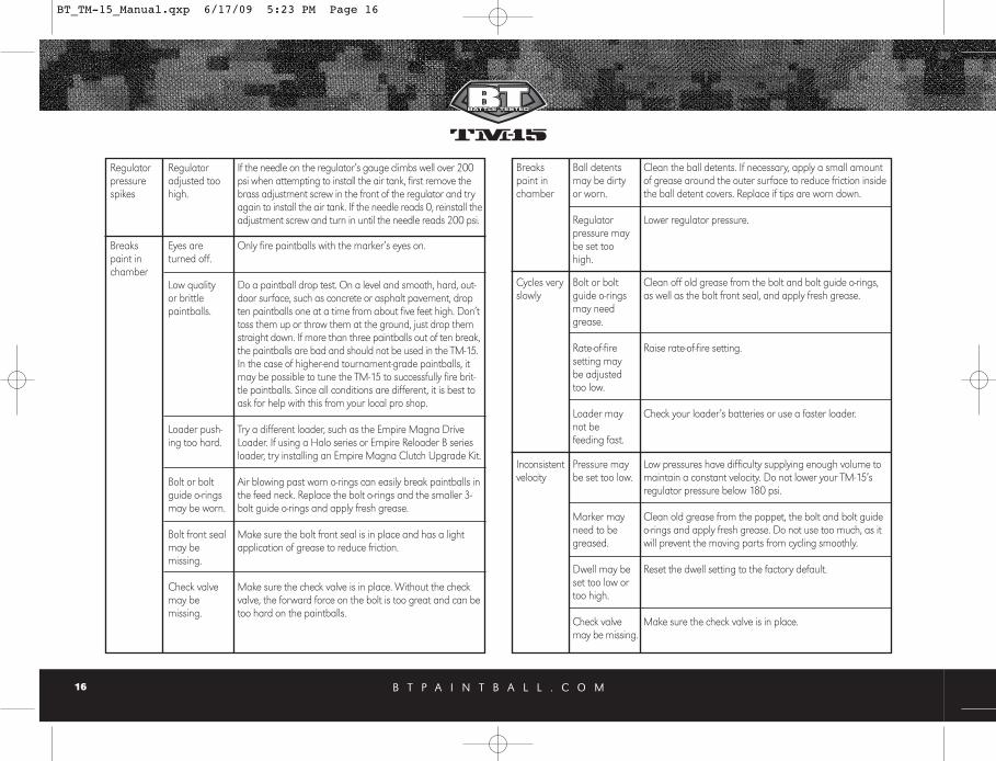
Breakspaint inchamber
Ball detentsmay be dirtyor worn.
Regulatorpressure maybe set toohigh.
Clean the ball detents. If necessary, apply a small amountof grease around the outer surface to reduce friction insidethe ball detent covers. Replace if tips are worn down.
Lower regulator pressure.
Cycles veryslowly
Bolt or boltguide o-ringsmay needgrease.
Rate-of-firesetting maybe adjustedtoo low.
Loader maynot be feeding fast.
Clean off old grease from the bolt and bolt guide o-rings,as well as the bolt front seal, and apply fresh grease.
Raise rate-of-fire setting.
Check your loader’s batteries or use a faster loader.
Inconsistentvelocity
Pressure maybe set too low.
Marker mayneed to begreased.
Dwell may beset too low ortoo high.
Check valvemay be missing.
Low pressures have difficulty supplying enough volume tomaintain a constant velocity. Do not lower your TM-15’s regulator pressure below 180 psi.
Clean old grease from the poppet, the bolt and bolt guideo-rings and apply fresh grease. Do not use too much, as itwill prevent the moving parts from cycling smoothly.
Reset the dwell setting to the factory default.
Make sure the check valve is in place.
Regulatorpressurespikes
Regulatoradjusted toohigh.
If the needle on the regulator’s gauge climbs well over 200psi when attempting to install the air tank, first remove thebrass adjustment screw in the front of the regulator and tryagain to install the air tank. If the needle reads 0, reinstall theadjustment screw and turn in until the needle reads 200 psi.
Breakspaint inchamber
Eyes areturned off.
Low qualityor brittlepaintballs.
Loader push-ing too hard.
Bolt or boltguide o-ringsmay be worn.
Bolt front sealmay be missing.
Check valvemay be missing.
Only fire paintballs with the marker’s eyes on.
Do a paintball drop test. On a level and smooth, hard, out-door surface, such as concrete or asphalt pavement, dropten paintballs one at a time from about five feet high. Don’ttoss them up or throw them at the ground, just drop themstraight down. If more than three paintballs out of ten break,the paintballs are bad and should not be used in the TM-15.In the case of higher-end tournament-grade paintballs, itmay be possible to tune the TM-15 to successfully fire brit-tle paintballs. Since all conditions are different, it is best toask for help with this from your local pro shop.
Try a different loader, such as the Empire Magna DriveLoader. If using a Halo series or Empire Reloader B seriesloader, try installing an Empire Magna Clutch Upgrade Kit.
Air blowing past worn o-rings can easily break paintballs inthe feed neck. Replace the bolt o-rings and the smaller 3-bolt guide o-rings and apply fresh grease.
Make sure the bolt front seal is in place and has a lightapplication of grease to reduce friction.
Make sure the check valve is in place. Without the checkvalve, the forward force on the bolt is too great and can betoo hard on the paintballs.
BT_TM-15_Manual.qxp 6/17/09 5:23 PM Page 16

B T P A I N T B A L L . C O M 17
Inconsistentvelocity
Battery maybe low.
Poppet o-ringmay be worn.
Replace battery with a fresh brand name alkaline 9-volt.
Replace poppet o-ring and apply fresh grease.
Velocitydrops offwhen firingmultipleshots
Air tank is notscrewed all theway into theTM-15’s regula-tor ASA.
If during rapid firing the first ball comes out of the barrel atfull velocity and following shots decrease substantially,watch the gauge on the TM-15 regulator to see if the nee-dle drops down significantly and is slow to come back tothe set pressure. This is typically the result of not screwingyour air tank in enough. When screwing your air tank intothe TM-15's regulator ASA, it is important to not stop assoon as the marker pressurizes, but to continue turninguntil the air tank stops. It is also acceptable to install the airtank when it is empty, then have it filled by a professionalwhile it is installed. This will ensure that you get the maxi-mum air flow from your air tank.
Scratcheson bolt
Spring may bedamaged.
This can cause negative performance. The main spring shouldbe repaired by a trained technician or it can just be replaced.
Selectorswitch notworking
Selector maybe installedincorrectly
Check to be certain that the selector switch is installed withkeys facing down toward the trigger spring.
Leaks attimes whileshootingmultipleshots
Poppet may besticking open.
Battery may below.
Solenoid maybe stickingopen.
Clean the old grease from the poppet o-ring and applyfresh grease. If that doesn't help, replace the poppet o-ringand apply fresh grease.
Replace battery with a fresh brand name alkaline 9-volt.
If the solenoid is sticking open occasionally, the regulatorpressure may be set too high. If the pressure is set to 200psi or less, then the solenoid may be filled with dirt and/orgrease. See Maintenance section for instructions on how toclean the solenoid.
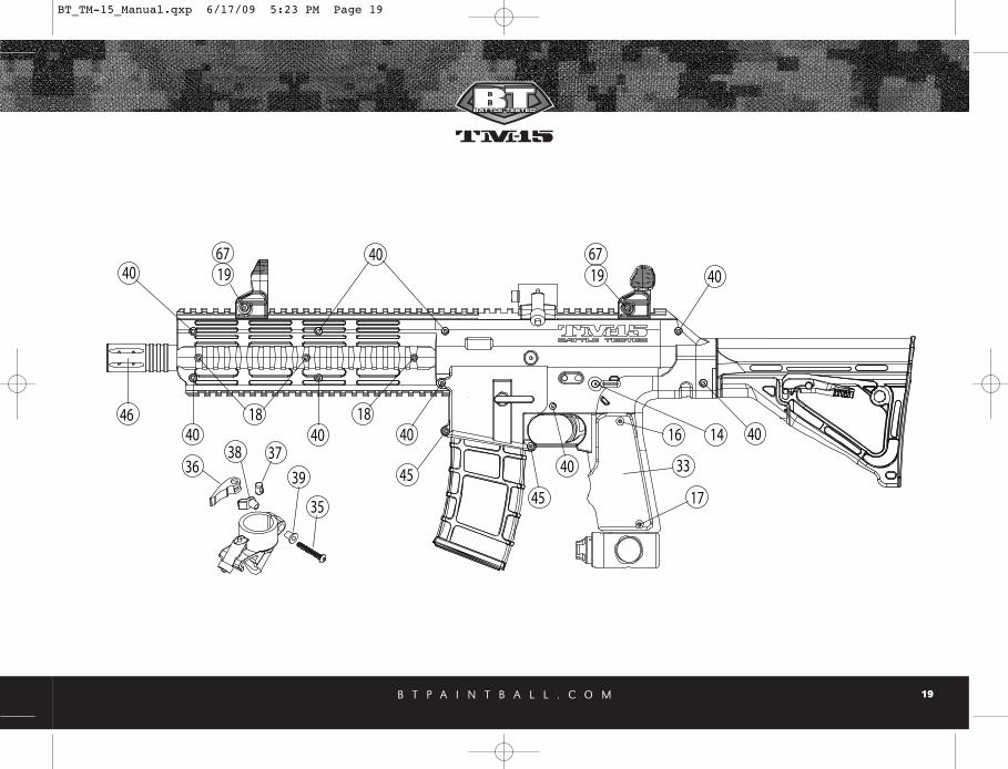
Schematic # Description SKU#1 CHECK VALVE (air restricter) 175312 BOLT RUBBER TIP 175333 BOLT / BOLT GUIDE LARGE O-RING 175344 SPRING MAIN 175355 BOLT GUIDE SMALL O-RING 175376 BOLT GUIDE CAP O-RING 175387 POPPET O-RING 175408 BALL DETENT ASSEMBLY (complete) 175419 REGULATOR CAP SET SCREW (4-48 x .125 cup point) 1759910 TRIGGER SET SCREW ( 6-32 x .250 flat point) 1760211 POPPET SPRING 1762312 POPPET ASSEMBLY (with replaceable tip) 1762813 POPPET SEAL 1762914 SELECTOR SCREW (flat head 4-40 x .5) 1765015 CIRCUIT BOARD SCREW (button head 6-32 x .157) 1765216 GRIP SCREW-TOP (button head 6-32 x .250) 1765317 GRIP SCREW-BOTTOM (button head 6-32 x .438) 1765418 PICATINNY RAIL SCREW (socket head 6-32 x .5) 1765519 FOLDING SIGHT HEX NUT (6-32 .25 wide x .092 thick) 1765720 SOLENOID SCREW (button head 10-24 x .250) 1765821 BOLT GUIDE RETENTION SCREW (custom) 1765922 BOLT 1766123 BOLT GUIDE CAP 1766424 SOLENOID ASSEMBLY (complete) 1766525 SOLENOID SPACER (brass) 1767026 REGULATOR ASSEMBLY (complete) 1767127 REGULATOR GAUGE (plain 300 psi) 1767228 MAIN BODY 1767729 CIRCUIT BOARD 17679
17. Diagrams and Parts List
BT_TM-15_Manual.qxp 6/17/09 5:23 PM Page 17

B T P A I N T B A L L . C O M18
61
10 62 59 532 22 3 5
5268 13
7 1112 6
5432
43
44
60
20
25
24
1
30
8
29
15
23
505556
57
27
63
47
9
51 64
3
66
6548
34
21
42 3158
4128
26
45
4 49
BT_TM-15_Manual.qxp 6/17/09 5:23 PM Page 18
B T P A I N T B A L L . C O M 19
3638 37
39
35
4018
40
40 40
40
40
17
16 14
6719
40 6719
1840
46
33
4545
BT_TM-15_Manual.qxp 6/17/09 5:23 PM Page 19

B T P A I N T B A L L . C O M20
Schematic # Description SKU#30 SOLENOID AIR TRANSFER O-RINGS 1768231 LIGHT PIPE 1771032 POWER BUTTON 17712not shown BATTERY HARNESS 1771533 RUBBER GRIP 1771734 CLAMPING FEED ELBOW (complete) 1775735 QUICK RELEASE SCREW (button head 8-32 X 1.250) 1775936 LEVER QUICK RELEASE 1776037 NUT QUICK RELEASE 1776138 SEAT QUICK RELEASE 1776239 SPACER QUICK RELEASE 1776340 SHELL SCREW (socket head 6-32 x .625) 1781041 FRAME SCREW ( flat head 6-32 X .625) 1781142 MAGAZINE RELEASE SCREW (button head 4-40 x .250) 1781243 TRIGGER ACTIVATION SET SCREW (w/magnet) 1781344 TRIGGER SET SCREW (6-32 X 1.00 cup point) 1781445 BODY RETENTION SCREW (socket head 6-32 x .750) 1781546 14 INCH BARREL 1781647 SHELL LEFT SIDE 1781748 SHELL RIGHT SIDE 1781849 SHELL ACCESS PANEL 1781950 PICATINNY SIDE RAIL (removable) 1782051 STOCK COVER PLATE 1782152 VELOCITY ADJUSTER COVER 1782253 BATTERY HARNESS HOLDER 1782354 MAGAZINE 1782455 MAGAZINE RELEASE ARM 1782556 MAGAZINE RELEASE ARM SPRING 1782657 MAGAZINE RELEASE ARM SPRING CAP 1782758 SELECTOR SWITCH ARM 17828
Schematic # Description SKU#59 SELECTOR SWITCH SHAFT (complete with magnets) 1782960 SINGLE TRIGGER ASSEMBLY 1783061 SINGLE TRIGGER GUARD 1783162 TRIGGER SPRING 1783263 TM-15 AIR TRANSFER TUBE 17833not shown MAIN WIRING HARNESS 1783464 CARBINE STOCK ASSEMBLY (complete) 1783565 FRONT SIGHT (complete w/hardware) 1784366 REAR SIGHT (complete w/hardware) 17844not shown BT SHELL JEWEL 1784967 SIGHT BODY SCREW (socket head 6-32 x 1.125) 1785068 BOLT GUIDE (fits TM-15 and TM-7) 17851not shown TM-15 RIP-CLIP™ ADAPTER PLATE (Rip-Clip™not included) 17852not shown TM-15 RIP-CLIP™ RAIL LOCKING SCREW KIT (Rip-Clip™not included) 38445
ACCESSORIES & PARTS KITS SKU#BT TM-15 TEAM PARTS KIT 17798BT TM-15 PLAYER PARTS KIT 17799TM-15 DOUBLE TRIGGER KIT 52071BT FOLDING FOREGRIP (TM-7 Style) 52081BT IRON SIGHT SET 53021
BT_TM-15_Manual.qxp 6/17/09 5:23 PM Page 20