Brushless Motor Controller Report - Andy...
20
Brushless Motor Controller Report Spring 2010 May 15, 2010 Brian Clementi MAE of 2010 322 Bogert Ave Ridgewood, NJ 07450 (201) 421-9507 [email protected] MAE 4900 Final Report 6 credits, two semesters Spring 2010 Biorobotics and Locomotion Lab Cornell University
Transcript of Brushless Motor Controller Report - Andy...

Brushless Motor Controller Report
Spring 2010
May 15, 2010
Brian ClementiMAE of 2010
322 Bogert AveRidgewood, NJ 07450
(201) [email protected]
MAE 4900 Final Report6 credits, two semesters
Spring 2010
Biorobotics and Locomotion LabCornell University

2
Table of ContentsI. Introduction ..................................................................................................................... 3II. Methods and Results ...................................................................................................... 5
A. Motor Description ...................................................................................................... 5B. The Motor Controller Board ...................................................................................... 6
i. Building the board ................................................................................................... 6ii. Connecting Boards.................................................................................................. 7
D. Motor Controller ...................................................................................................... 10III. Discussion ................................................................................................................... 12IV. Appendices ................................................................................................................. 13

3
I. Introduction
In the world of robotics, there are only a finite number of ways to actuate a robot.
When the goal is to minimize the cost of transport and improve the energy efficiency, the
most logical selection for actuation is electric motors. Other methods of actuation, like
hydraulics or pneumatics, have major issues preventing energy efficiency. A hydraulic
engine is extremely powerful, but consumes large amounts of energy and requires
continuous running, even if the robot is not moving. Pneumatic systems require large,
heavy storage tanks for compressed air, necessitating large air compressors to fill up the
tanks and often the energy consumed compressing the air is not considered in the cost of
transport. Conversely, electric motors are capable of large amounts of power, and are
relatively light weight. A typical electric motor is capable of 200 watts per kilogram,
while a typical human muscle is only capable of about 50 watts per kilogram of power.
Electric motors come in two major varieties: brushed and brushless. Brushed
motors are the most common and the easiest to use. Brushed motors work by having two
magnets in the stator and an electromagnet in the rotor. The motor continues to spin by
the electromagnet changing orientation, which is controlled by the brushes that act as
contact switches. Brushed motors are very easy to use, and will run by simply applying a
dc voltage across the motor leads. The current Ranger robot is the laboratory uses
exclusively brushed motors, with motor controllers set up for the brushed motors.
There are several issues with brushed motors. The constant contact of the brushes
will limit the top speed of the motor and eventually the brushes wear out, necessitating
replacement. The brushes also result in sparking and electrical noise, which leads to
variation in the motor constants, as observed by the laboratory. Another disadvantage is
that the component of the motor that heats up, the electromagnet, is in the rotor and is
nearly impossible to cool without opening the motor to blow air through it.
Conversely, brushless motors do not contain brushes. The electromagnet for the
motor is in the stator and does not rotate, while the rotor contains rare earth magnets.
The changing of the polarity to continue to make the motor spin is controlled by a
computer, making the control more precise and efficient, since the computer can factor in

4
the speed of the motor. Without the brushes, the motor has less frictional losses and less
variable motor constants and properties. Also, with the electromagnets in the stator the
motor will be much easier to cool, which means the motor will be able to run longer at
higher power values without overheating.
The major drawback of the brushless motor is that they are much more difficult to
control. A brushless motor requires a computer to sense the position of the rotor and
apply the appropriate voltage across the appropriate electromagnet to force the motor to
spin. Hence, the goal of this project is to modify a motor controller board to enable
control of a brushless motor and create a motor controller to run the motor.

5
II. Methods and Results
A. Motor DescriptionThe motor used is a Maxon EC32, 32 mm, brushless, 80 Watt order number
118888, corresponding to the 18 volt motor. The spec sheet for the motor is located in
the appendix. A picture of the motor is displayed below in Figure 1. The motor is
approximately 2.5 inches long, 1.25 inches across, and 270 grams.
As depicted in the figure, the motor has eight wires attaching to it. There is one
power wire for each of the three windings, one power wire for the Hall effect sensors, one
ground wire for the Hall effect sensors, and one power wire for each of the three Hall
effect sensors. The Hall sensors are built into the motor to detect the position of the
rotor. The Hall sensors return a high value when rotor is in one orientation and a low
when the rotor is 180 degrees away from the high. In actual use, the Hall sensor returns a
high for the 180 degree section while the rotor is closest to the sensor and a low voltage
of zero for the rest of the time. The motor uses three Hall sensors, and by determining
which sensors are on at any given time, the appropriate orientation of the electromagnetic
field can be applied.
Figure 1: Picture of the brushless motor supplied.

6
B. The Motor Controller Board
In order to implement a controller for the brushless motor, it is necessary for the
H-bridge to have control over the three motor winding; this means that the motor
controller board H-bridge must have a total of six MOSFETs, with each of the windings
connected to the board between two of the MOSFETs. The current motor controller
boards used on the Ranger only contain four MOSFETs, because they were built for
brushed motors. The simplest method to reach the necessary number of MOSFETs,
without redesigning an entire board, is to build a pseudo-motor controller board. The
pseudo board is incapable of being used by itself; it contains no processor, it only
contains the motor controller portion of the board, but when connected to the old motor
controller boards, it is successfully used as a brushless motor controller.
i. Building the board
Although the pseudo motor controller only requires an additional two MOSFETs,
the set of four were used on the board. This means the board has all the motor controller
parts necessary to run a brushless motor, and the board is capable of being used as a
backup for the current motor controller boards if necessary.
A picture of the finished product is depicted below in Figure 2, as described
above only the motor controller components are on the board, so only approximately half
the board is populated. The board was populated by a process called surface mount
soldering. Using the procedure outlined in the wiki entry entitled: “How-to guide for
surface mount soldering” compiled by Emily McAdams, the parts are soldered onto the
empty circuit board.

7
ii. Connecting Boards
Upon completion of the pseudo motor controller board, it is necessary to connect
the two boards together, relaying the appropriate information or power between the
boards. To connect the boards, a four pin and a six pin connector were used to relay
information to unused jacks on the original board, as well as an additional wire that was
directly soldered to each board. This is depicted in Figure 3 below.
Figure 2: The top (left) and bottom (right) sides of the competed pseudo motor controller board.
Figure 3: Displays the connections between the two motor controller boards.

8
The four pin connector is largely used to power the new pseudo board, and
connects to the new board at the serial port at J6. The power supplied to the board is
3V3D, and is applied through pin three of the jack. Pin one of the jack supplies a
reference ground, referred to as GND-C. The PWM for the board is supplied through pin
four, and LSA is supplied through pin two. Pin one connects to the pseudo board at pin
one of J3, pin two connects at pin 3 of U4, pin three connects at pin 1 of J1, and pin four
connects at pin 2 of U4. Each of these connections is soldered onto the appropriate place
on the pseudo board. The four pin connector required a small modification of the old
board. At pin four, there was a resistor connecting a 5 volt reference voltage to the
output. This resistor was removed because the reference voltage is unnecessary. The
exact technical modification was that resistor R105 and resistor R24 were removed and
R105 was placed across R111.
For the six pin connector, only two of the pins are utilized. Pin two is the battery
current output, and pin five is the motor current output. This information is supplied
back to the old motor controller board. The six pin connector attaches to the old motor
controller board at J2. Pin two of the six pin connector is soldered directly to the resistor
pad R11 and pin 5 is soldered directly to the resistor pad at R9 on the pseudo board.
The final board to board connection was the watchdog timer (WDT). The WDT
was connected by attaching a small magnet wire between the two boards at the necessary
points. This magnet wire was soldered directly to the boards by a via at pin 30 of the
MCU on both boards.
The final connection necessary is to connect the Hall effect sensors to the old
motor controller board. This requires three free digital inputs. Therefore, the Hall effect
sensors are set up with a connector into J9 on the old motor controller board. The Hall
sensors require a reference voltage applied to the signal across a resistor. Therefore, the
available 5 volts at pin four of J9 were used as the reference voltage. This process
involves soldering three resistors to pin four and then attaching one of the resistors to
each Hall sensor output. The entire apparatus was covered with heat shrink to make it
look more appealing. Schematics of the boards and connections are displayed below.

9
It is also important to setup the motor power correctly. The power supply at J7
shown in Figure 4 is the power supply for the motor controller board. The motor itself
must be powered. This configuration is depicted in Figure 5 below. In the figure, the
blue, black, and red wires coming from the motor correspond directly with the actual
white, black, and red winding power wires of the motor.
Figure 4: Depicts the connections to the original motor controller board. Specifically the interactions with the pseudo board.
Figure 5: Depiction of motor power connections.

10
D. Motor Controller
The basic principal of the motor controller is to use the Hall effect sensors to
determine the orientation of the rotor and apply a magnetic field perpendicular to the
rotor magnets. To control the speed of the motor, the voltage applied is Pulse Width
Modulated (PWM). It is also necessary to determine the speed of the motor, which can
be accomplished by measuring the time for the Hall sensors to go through one full
rotation, corresponding to one revolution of the motor. The diagram below shows the
possible sequence of MOSFET activity to achieve one full rotation of the rotor. In the
diagram, each winding is attached between two MOSFETs, and by controlling which
MOSFETs are active controls the flow of current into the motor and ultimately the
direction of the magnetic field.
The actual implementation of this strategy utilizes a block commutation scheme
provided in the Maxon EC motor guide, included in the appendix. This strategy is
depicted in Figure 7, below. As depicted below there are six cases, where the high sensor
is: 1, 1 and 2, 2, 2 and 3, 3, 3 and 1. In the code, the variable hall_sensor_code is
comprised of three bits: sensor 3 is assigned bit 0, sensor 2 is assigned bit 1, and sensor 1
is assigned bit 2. The actual motor code takes on a switch-case structure, which allows
Figure 6: Depicts the flow of current through the MOSFETs and motor windings, as a progression of the rotation of the motor. The figure is from the Brushless DC motor control using the LPC2141 article from the NPX website.

11
for the six cases listed above, as well as the potential to go in the reverse direction. In
each case, it is first determined which winding is getting the voltage applied to it. Next, it
is determined which two MOSFETs are set to the on position. For example, phase 1 in
the diagram below has Hall sensors 1 and 3 set to on. This gives a value of 101 for
hall_sensor_code, in binary, or 5 in decimal. In the diagram, U1-2 is on, with the shaded
portion on the positive side. This means that the lowside MOSFETs for windings 1 and 2
are set to on, and the lowside MOSFET for winding 3 is off. Also, since the top is
shaded, the first number of the subscript has the voltage applied to it, so in the code,
winding 1 gets the voltage. This example is depicted as the second state in Figure 6. The
specific section of code is as follows:
//***************************case 5: //0b101 Phase I { PWM_PHASE_A = pwm; PWM_PHASE_B = 0; PWM_PHASE_C = 0; LOWSIDE_PHASE_A_ON LOWSIDE_PHASE_B_ON LOWSIDE_PHASE_C_OFF break; }//***************************
Figure 7: Block commutation scheme from Maxon’s motor guide.

12
III. Discussion
Upon the completion of the project, I have a working motor controller for a
brushless dc motor; however, the motor controller can be improved. Currently all of the
code for the motor controller is in the main loop of the c file. This may cause a problem
at high speed, since the motor may be turning faster than the main loop can keep up with.
This problem could be solved by putting the code into an interrupt; let the motor run until
a hall sensor switches on, then apply the necessary voltage to the necessary windings.
This would also be useful for determining the speed of the motor by counting the
interrupts. A working motor controller has been made, but many modifications are
necessary before the code is good enough to use on a robot.

13
IV. Appendices
Motor Controller Code:
#include <includes.h>
void FIQ_Handler(void) __irq{}
int main (void){signed short hall_sensor_code = 0;signed short motor_forward = 0;unsigned short pwm = 100;unsigned long watchdog_counter = 0;
#define LOWSIDE_PHASE_A_OFF FIO0CLR = (1<<11); // turn off low side A enable output#define LOWSIDE_PHASE_B_OFF FIO1CLR = (1<<17); // turn off low side B enable output#define LOWSIDE_PHASE_C_OFF FIO0CLR = (1<<10); // turn off low side C enable output
#define LOWSIDE_PHASE_A_ON FIO0SET = (1<<11); // turn on low side A enable output#define LOWSIDE_PHASE_B_ON FIO1SET = (1<<17); // turn on low side B enable output#define LOWSIDE_PHASE_C_ON FIO0SET = (1<<10); // turn on low side C enable output
#define PWM_PHASE_A PWMMR6 #define PWM_PHASE_B PWMMR2#define PWM_PHASE_C PWMMR5
init_hardware(); //init_interrupts(); while(1) {
//Set up the Hall effect sensor code. This could be way shorter,//but this way is easy to fiddle with until the phases are right. hall_sensor_code = 0; if (FIO0PIN & (1<<5)) { hall_sensor_code |= (1<<0); // Hall effect sensor 3 (C), bit zero } if (FIO0PIN & (1<<16)) { hall_sensor_code |= (1<<1); // Hall effect sensor 2 (B), bit one }
14
if (FIO0PIN & (1<<29)) { hall_sensor_code |= (1<<2); // Hall effect sensor 1 (A), bit two } if (!motor_forward) { hall_sensor_code = - hall_sensor_code; // Let's try making it go backward too }
switch(hall_sensor_code) { case 5: //0b101 Phase I { PWM_PHASE_A = pwm; PWM_PHASE_B = 0; PWM_PHASE_C = 0; LOWSIDE_PHASE_A_ON LOWSIDE_PHASE_B_ON LOWSIDE_PHASE_C_OFF break; } case 4: //0b100 Phase II { PWM_PHASE_A = pwm; PWM_PHASE_B = 0; PWM_PHASE_C = 0; LOWSIDE_PHASE_A_ON; LOWSIDE_PHASE_B_OFF; LOWSIDE_PHASE_C_ON; break; } case 6: //0b110 Phase III { PWM_PHASE_A = 0; PWM_PHASE_B = pwm; PWM_PHASE_C = 0; LOWSIDE_PHASE_A_OFF; LOWSIDE_PHASE_B_ON; LOWSIDE_PHASE_C_ON; break; } case 2: //0b010 Phase IV { PWM_PHASE_A = 0; PWM_PHASE_B = pwm;

15
PWM_PHASE_C = 0; LOWSIDE_PHASE_A_ON; LOWSIDE_PHASE_B_ON; LOWSIDE_PHASE_C_OFF; break; } case 3: //0b011 Phase V { PWM_PHASE_A = 0; PWM_PHASE_B = 0; PWM_PHASE_C = pwm; LOWSIDE_PHASE_A_ON; LOWSIDE_PHASE_B_OFF; LOWSIDE_PHASE_C_ON; break; } case 1: //0b001 Phase vI { PWM_PHASE_A = 0; PWM_PHASE_B = 0; PWM_PHASE_C = pwm; LOWSIDE_PHASE_A_OFF; LOWSIDE_PHASE_B_ON; LOWSIDE_PHASE_C_ON; break; } //Backwards counterclockwise case -5: //-0b101 Phase I R { PWM_PHASE_A = 0; PWM_PHASE_B = pwm; PWM_PHASE_C = 0; LOWSIDE_PHASE_A_ON; LOWSIDE_PHASE_B_ON; LOWSIDE_PHASE_C_OFF; break; } case -4: //-0b100 Phase II R { PWM_PHASE_A = 0; PWM_PHASE_B = 0; PWM_PHASE_C = pwm; LOWSIDE_PHASE_A_ON; LOWSIDE_PHASE_B_OFF; LOWSIDE_PHASE_C_ON; break;

16
} case -6: //-0b110 Phase III R { PWM_PHASE_A = 0; PWM_PHASE_B = 0; PWM_PHASE_C = pwm; LOWSIDE_PHASE_A_OFF; LOWSIDE_PHASE_B_ON; LOWSIDE_PHASE_C_ON; break; } case -2: //-0b010 Phase Iv R { PWM_PHASE_A = pwm; PWM_PHASE_B = 0; PWM_PHASE_C = 0; LOWSIDE_PHASE_A_ON; LOWSIDE_PHASE_B_ON; LOWSIDE_PHASE_C_OFF; break; } case -3: //-0b011 Phase V R { PWM_PHASE_A = pwm; PWM_PHASE_B = 0; PWM_PHASE_C = 0; LOWSIDE_PHASE_A_ON; LOWSIDE_PHASE_B_OFF; LOWSIDE_PHASE_C_ON; break; } case -1: //-0b001 Phase VI R { PWM_PHASE_A = 0; PWM_PHASE_B = pwm; PWM_PHASE_C = 0; LOWSIDE_PHASE_A_OFF; LOWSIDE_PHASE_B_ON; LOWSIDE_PHASE_C_ON; break; } default: //all off { PWM_PHASE_A = 0; PWM_PHASE_B = 0; PWM_PHASE_C = 0;

17
LOWSIDE_PHASE_A_OFF; LOWSIDE_PHASE_B_OFF; LOWSIDE_PHASE_C_OFF; break; } }
PWMLER= (PWMLER|0x65) & ~PWMLER_RB; //update PWM values.
if (watchdog_counter++ > 1000) {
watchdog_counter = 0; } else if (watchdog_counter++ > 500) { FIO0SET = (1<<6); // turn on watchdog timer output } else { FIO0CLR = (1<<6); // turn off watchdog timer output watchdog_counter++; } }}

Operating Range Comments
Continuous operationIn observation of above listed thermal resistance(lines 17 and 18) the maximum permissible windingtemperature will be reached during continuousoperation at 25°C ambient.= Thermal limit.
Short term operationThe motor may be briefly overloaded (recurring).
Assigned power rating
n [rpm]
max
onE
Cm
otor
maxon Modular System Overview on page 16 - 21
Specifications
156 May 2009 edition / subject to change
Stock programStandard programSpecial program (on request)
Order Number
EC 32 �32 mm, brushless, 80 Watt, � approved
Thermal data17 Thermal resistance housing-ambient 5.4 K / W18 Thermal resistance winding-housing 2.5 K / W19 Thermal time constant winding 15.4 s20 Thermal time constant motor 1180 s21 Ambient temperature -20 ... +100°C22 Max. permissible winding temperature +125°C
Mechanical data (preloaded ball bearings)23 Max. permissible speed 25000 rpm24 Axial play at axial load < 8 N 0 mm
> 8 N max. 0.14 mm25 Radial play preloaded26 Max. axial load (dynamic) 5.6 N27 Max. force for press fits (static) 110 N
(static, shaft supported) 1200 N28 Max. radial loading, 5 mm from flange 28 N
Other specifications29 Number of pole pairs 130 Number of phases 331 Weight of motor 270 g
Values listed in the table are nominal.
Connection motor (Cable AWG 22)red Motor winding 1black Motor winding 2white Motor winding 3Connection sensors (Cable AWG 26)1)
green VHall 4.5 ... 24 VDCblue GNDred / grey Hall sensor 1black / grey Hall sensor 2white / grey Hall sensor 3Wiring diagram for Hall sensors see page 27
1) Not lead through in combination with resolver.
Planetary Gearhead�32 mm0.75 - 4.5 NmPage 232
Encoder HED_5540500 CPT,3 channelsPage 269 / 271Resolver Res 26�26 mm10 VPage 278
118891 118892 118888 118889 118893 118890
Motor DataValues at nominal voltage
1 Nominal voltage V 12.0 18.0 18.0 24.0 36.0 48.02 No load speed rpm 15000 14300 13000 11000 14700 113003 No load current mA 901 555 487 286 289 1484 Nominal speed rpm 13600 12800 11600 9510 13200 97905 Nominal torque (max. continuous torque) mNm 37.5 40.1 41.2 43.6 39.7 42.66 Nominal current (max. continuous current) A 5.82 3.88 3.61 2.37 1.98 1.197 Stall torque mNm 428 443 407 355 454 3538 Starting current A 57.2 37.4 31.4 17.3 19.7 8.849 Max. efficiency % 77.0 77.6 77.1 76.4 77.7 76.2
Characteristics10 Terminal resistance phase to phase � 0.21 0.481 0.573 1.39 1.83 5.4311 Terminal inductance phase to phase mH 0.03 0.0752 0.09 0.226 0.285 0.85612 Torque constant mNm / A 7.48 11.8 13.0 20.5 23.1 40.013 Speed constant rpm / V 1280 806 737 465 414 23914 Speed / torque gradient rpm / mNm 35.8 32.7 32.6 31.5 32.8 32.515 Mechanical time constant ms 7.49 6.86 6.82 6.59 6.87 6.816 Rotor inertia gcm2 20.0 20.0 20.0 20.0 20.0 20.0
Planetary Gearhead�32 mm0.75 - 6.0 NmPage 234 / 236
M 1:2
Recommended Electronics:DECS 50/5 Page 288DEC 50/5 289DECV 50/5 295DEC 70/10 295DES 50/5 296EPOS2 24/5 303EPOS2 50/5 303EPOS 70/10 303EPOS P 24/5 306Notes 20
Spindle Drive�32 mmPage 251 / 252 / 253

26 Technology – short and to the point May 2009 edition / subject to change
max
on
EC
mo
tor
Block commutation
0° 60° 120° 180° 240° 300° 360°
EMK
EMK
Sensorless commutation
1
2 2
3 3
maxon EC motor ironless windingTechnology – short and to the point
Characteristics of maxon EC motors− Brushless DC motor− Long service life− Speeds of up to 50 000 rpm and higher
are possible− Highly efficient− Linear motor characteristics, excellent
control properties− Ironless winding system maxon®
with three phases in the stator− Lowest electrical time constant and
low inductance− No detent− Good heat dissipation, high overload
capacity− Rotating Neodymium permanent magnet
with 1 or 2 pole pairs.− Lowest residual unbalance
Characteristics of the maxon EC-max range− attractive price/performance ratio− robust steel casing− speeds of up to 20 000 rpm− rotor with 1 pole pair
Characteristics of the maxon EC powermax range− Highest power density thanks to rotor
with 2 pole pairs− Knitted winding system maxon® with optimi-
sed interconnection of the partial windings− Speeds of up to 25 000 rpm− High-quality magnetic return material to
reduce eddy current losses− Mechanical time constants below 3 ms
Bearings and service life
The long service life of the brushless design can only be properly exploited by using preloaded ball bearings.− Bearings designed for tens of thousands
of hours.− Service life is affected by maximum speed,
residual unbalance and bearing load.
Electronical commutation
Block commutationRotor position is reported by three in-built Hall sensors. The Hall sensors arranged offset by 120° provide six different signal combinations per revolution. The three partial windings are now supplied in six different conducting phases in accordance with the sensor information. The current and voltage curves are block-shaped. The switching position of each electronic com-mutation is offset by 30° from the respective torque maximum.
Properties of block commutation– Relatively simple and favorably priced
electronics– Torque ripple of 14 %– Controlled motor start-up– High starting torques and accelerations
possible – The data of the maxon EC motors are
determined with block commutation.
Possible applications– Highly dynamic servo drives– Start/stop operation– Positioning tasks
Sensorless block commutationThe rotor position is determined using the progression of the induced voltage. The electro-nics evaluate the zero crossing of the induced voltage (EMF) and commute the motor current after a speed dependent pause (30° after EMF zero crossing). The amplitude of the induced voltage is dependent on the speed. When stalled or at low speed, the voltage signal is too small and the zero crossing cannot be detected precisely. This is why special algorithms are required for star-ting (similar to stepper motor control). To allow EC motors to be commuted without sensors in a D arrangement, a virtual star point is usually created in the electronics.
Properties of sensorless commutation– Torque ripple of 14 % (block commutation)– No defined start-up– Not suitable for low speeds– Not suitable for dynamic applications
Possible applications– Continuous operation at higher speeds– Fans
LegendThe commutation angle is based on the length of a full commutation sequence (360°e). The length of a commutation interval is therefore 60°e. The commutation rotor position is identical to the motor shaft position for motors with 1 pole pair.The values of the shaft position are halved for motors with 2 pole pairs.
Program
– EC-Program– EC-max-Program– EC-powermax
– with Hall sensors– sensorless– with integrated electronics
1 Flange
2 Housing
3 Laminated steel stack
4 Winding
5 Permanent magnet
6 Shaft
7 Balancing disks
8 Print with Hall sensors
9 Control magnet
= Ball bearing
+ Spring (bearing preload)
27May 2009 edition / subject to change Technology – short and to the point
max
on
EC
mo
tor
0° 60° 120° 180° 240° 300° 360°Turning angle
Sinusoidal phase currents
Block-shaped phase currents
Currents in sine and block commutation
Wiring diagram for Hall sensors
123
45
7
+8
6
=9
=
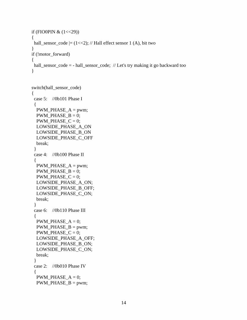
Hall sensor circuit
The open collector output of Hall sensors does not normally have its own pull-up resistance, as this is integral in maxon controllers. Any excep-tions are specifically mentioned in the relevant motor data sheets.
Winding arrangement
The maxon rhombic winding is divided into three partial windings, each shifted by 120°. The partial windings can be connected in two different manners - “Y” or “D”. This changes the speed and torque inversely proportional by the factor .However, the winding arrangement does not play a decisive role in the selection of the motor. It is important that the motor-specific parame-ters (speed and torque constants) are line with requirements.
The maximum permissible winding temperature is 125°C. (EC-max and EC-powermax 155°C).
For further explanations, please see page 141 or “The selection of high-precision microdrives” by Dr. Urs Kafader.
Sinusoidal commutationThe high resolution signals from the encoder or resolver are used for generating sine-shape motor currents in the electronics. The currents through the three motor windings are related to the rotor position and are shifted at each phase by 120 degrees (sinusoidal commutation). This results in the very smooth, precise running of the motor and, in a very precise, high quality control.
Properties of sinusoidal commutation– More expensive electronics– No torque ripple – Very smooth running, even at very low
speeds– Approx. 5% more continuous torque
compared to block commutation
Possible applications– Highly dynamic servo drives– Positioning tasks
Legend1Star point2Time delay 30°3Zero crossing of EMF
=2
34
5
7
6
=
8
1