Brunel University Professor Savvas Tassou - Grimsby · School of Engineering and Design ...
33
School of Engineering and Design www.brunel.ac.uk/about/acad/sed Refrigerated Display Cabinets Progress made and research and development issues Brunel University Professor Savvas Tassou
Transcript of Brunel University Professor Savvas Tassou - Grimsby · School of Engineering and Design ...

School of Engineering and Design
www.brunel.ac.uk/about/acad/sed
Refrigerated Display Cabinets
Progress made and research and development issues
Brunel University
Professor Savvas Tassou

School of Engineering and Design
www.brunel.ac.uk/about/acad/sed
1. Work started as a collaboration between Safeway Stores PLC and Brunel University back in 1994. CASE Studentship funded by EPSRC and Safeway– David Stribling
2. Followed by a PhD by Dr Weizhong Xiang3. A recent PhD by Dr Abas Hadawey4. A current PhD project by Ahmad Al-Sahhaf5. Other investigations funded by DEFRA and EPSRC (Drs
Deborah Datta, Richard Watkins and Issa Chaer).
Brief History
School of Engineering and Design
www.brunel.ac.uk/about/acad/sed
• Environmental test chamber to be able to test at EN441 conditions.
• Replication of refrigeration pack and typical supermarket control system in the laboratory for research on modelling and control
• CFD simulation – one of the 1st applications of CFD to display cabinet modelling
Test facilities and Modelling Tools
Condenser
Receiver
Heat Exchanger
Filter Drier
Display Case 1Display Case 2
Liqu
id L
ine
Flow
met
er
Compressor Pack
SV1
SV2
SV3
SV4
TEV
SV SOLENOID VALVE
TEV THERMOSTATIC Exp. VALVE
PRESSURE & TEMPERATURE SENSORS
LOW PRESSURE SIDE
DEFROST LINE
HIGH PRESSURE SIDE

School of Engineering and Design
www.brunel.ac.uk/about/acad/sed
b0
Fan
b1
u0
u1
u1
u1
u1
u1
60
240
250
250
250
380
45460
510
120
200b0
Fan
b1
u0
u1
u1
u1
u1
u1
60
240
250
250
250
380
45460
510
120
200
)()(
2
2000
wcm gH
ubD
ρρρ
−=
u0
TwarmTcold
Break throughu0
TwarmTcold
Break through
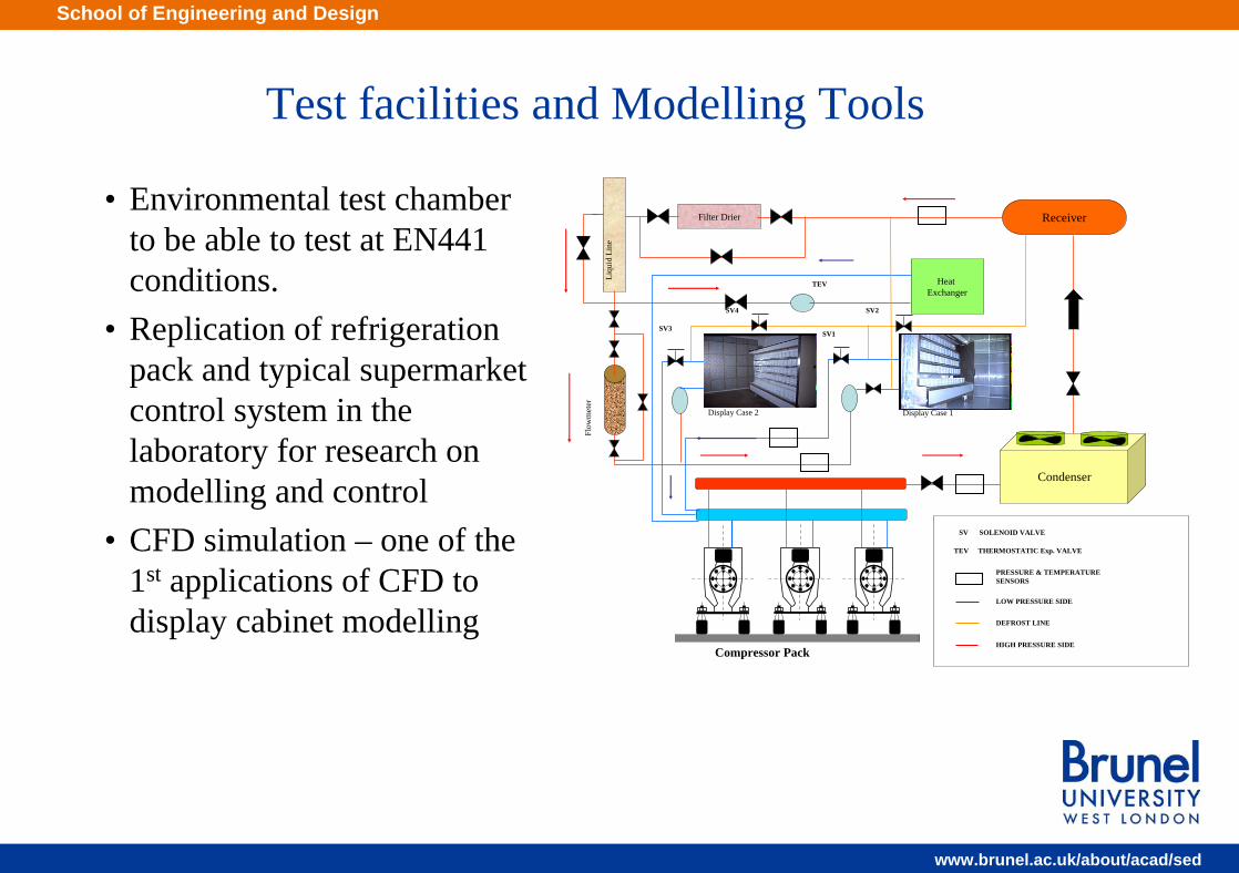
Deflection modulus = 0.14~0.18
1430
Multi-deck cabinet design issuesMulti-deck cabinet design issues
School of Engineering and Design
www.brunel.ac.uk/about/acad/sed
b0
Fan
b1
u0
u1
u1
u1
u1
u1
60
240
250
250
250
380
45460
510
120
200b0
Fan
b1
u0
u1
u1
u1
u1
u1
60
240
250
250
250
380
45460
510
120
200
)()(
2
2000
wcm gH
ubD
ρρρ
−=
Deflection modulus = 0.14~0.18
1430
Multi-deck cabinet design issuesMulti-deck cabinet design issues
H = Opening heightbo= Air curtain slot widthuo = air curtain initial velocityρc = density of cold air in cabinetρw= density of space airρo= density of air at air curtain discharge
⎥⎦
⎤⎢⎣
⎡⎟⎟⎠
⎞⎜⎜⎝
⎛−
=
w
o
c
o
oom
TT
TTHg
ubD2
2
.
.

School of Engineering and Design
www.brunel.ac.uk/about/acad/sed
Multi-deck cabinet design issuesMulti-deck cabinet design issues
Height of opening (m)
Minimum velocity (m/s)
Minimum air flow rate (m3 /s/m)
0.25 0.4 0.023
0.40 0.64 0.038
0.60 0.96 0.057
0.80 1.11 0.089
1.00 1.60 0.096
1.20 1.92 0.115
1.38 2.24 0.134
Minimum initial air curtain velocities for non-isothermal air curtains. Slot width = 60 mm
0.0
1.0
2.0
3.0
4.0
5.0
6.0
0.0 0.5 1.0 1.5 2.0 2.5 3.0 3.5 4.0
Initial velocity (m/s)
Tem
pera
ture
(°C
)

School of Engineering and Design
www.brunel.ac.uk/about/acad/sed
Multi-deck cabinet design issuesMulti-deck cabinet design issues
o
w
o
c
o
o bTT
TTHg
u⎟⎟⎠
⎞⎜⎜⎝
⎛−
=
2
2
..18.0
• Experiments and simulation have shown that for multi-deck cabinets H should be the maximum distance between shelves in the cabinet
• Increasing the slot width should reduce the velocity required to provide good sealing
• A loaded cabinet will require a lower air curtain velocity to provide good sealing
• Back panel flow to the shelves will aid the air curtain particularly when the cabinet is not fully loaded.
School of Engineering and Design
www.brunel.ac.uk/about/acad/sed
Multi-deck cabinet design issuesMulti-deck cabinet design issues
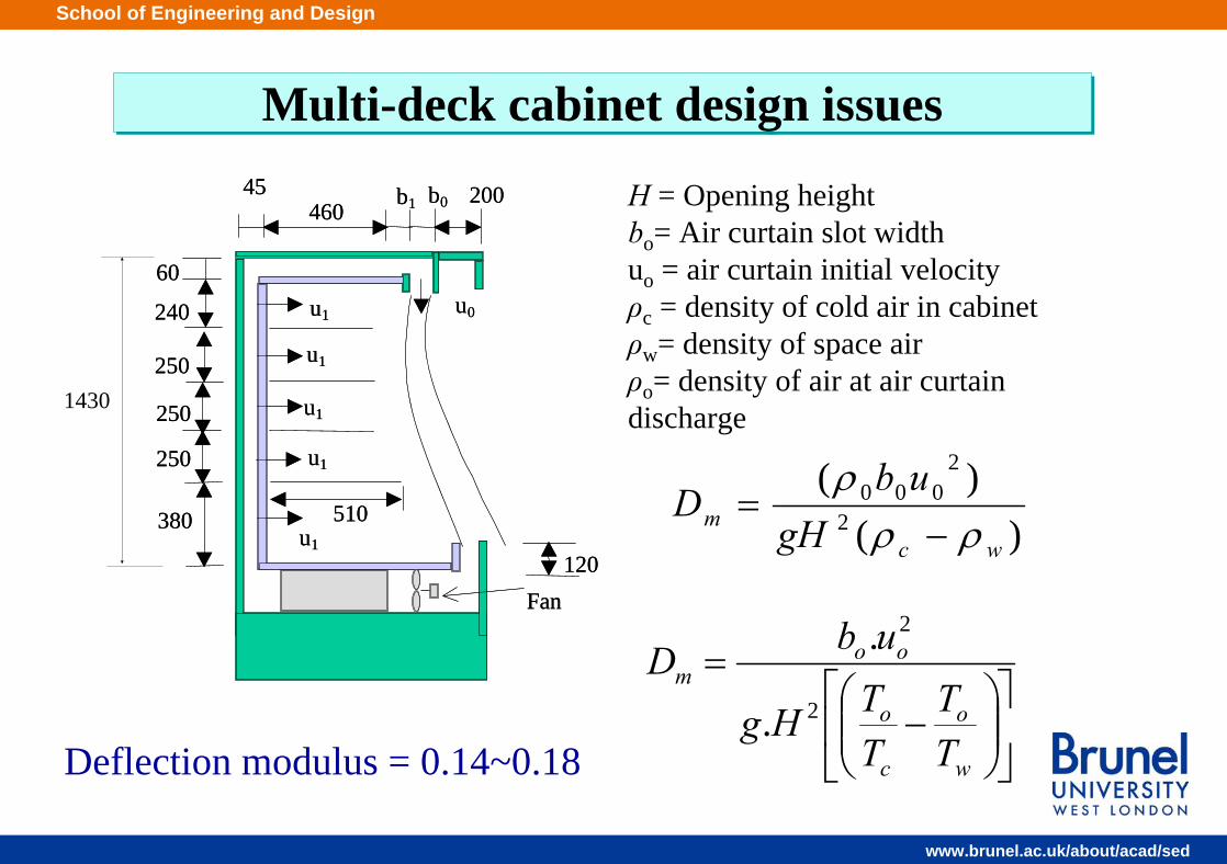
• Back panel flow to the shelves can help maintain lower product temperature
• High back panel flow reduces the flow requirement from the air curtain
• Increasing the air curtain flow increases the refrigeration load.
0.0
1.0
2.0
3.0
4.0
5.0
6.0
0.0 0.2 0.4 0.6 0.8 1.0 1.2 1.4Velocity (m/s)
Tem
pera
ture
(°C)
Back panel -0.038 m/sBack panel -0.075 m/sBack panel -0.113 m/s
0.0
0.2
0.4
0.60.8
1.0
1.2
1.4
1.6
0.0 0.2 0.4 0.6 0.8 1.0 1.2 1.4
Velocity (m/s)
Coo
ling
load
(kW
/m)
Back panel -0.038 m/sBack panel -0.075 m/sBack panel -0.113 m/s
School of Engineering and Design
www.brunel.ac.uk/about/acad/sed
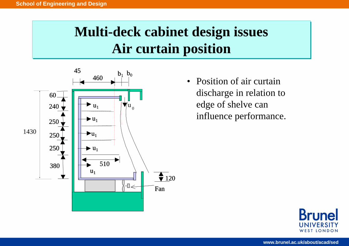
Multi-deck cabinet design issues Air curtain position
Multi-deck cabinet design issues Air curtain position
• Position of air curtain discharge in relation to edge of shelve can influence performance.
b0
Fan
b1
u 0
u1
u1
u1
u1
u1
60
240
250
250
250
380
45460
510
120
b0
Fan
b1
u1
u1
u1
u1
u1
60
240
250
250
250
380
45460
510
120
1430

School of Engineering and Design
www.brunel.ac.uk/about/acad/sed
Multi-deck cabinet design issues Air curtain position
Multi-deck cabinet design issues Air curtain position
0 mm 120 mm 60 mm
1300
1320
1340
1360
1380
1400
0 60 120
Distance of air curtain outlet from front shelf edge (mm)
Coo
ling
load
(W/m
)
276
276.5
277
277.5
278Cooling loadAverage product temperature
• Best performance achieved when b1= slightly above 0 mm• Increasing b1 increases average product temperature and cooling
load
School of Engineering and Design
www.brunel.ac.uk/about/acad/sed
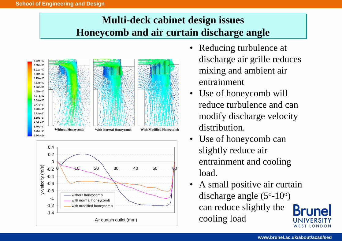
Multi-deck cabinet design issues Honeycomb and air curtain discharge angle
Multi-deck cabinet design issues Honeycomb and air curtain discharge angle
Without Honeycomb
With Normal Honeycomb With Modified Honeycomb
• Reducing turbulence at discharge air grille reduces mixing and ambient air entrainment
• Use of honeycomb will reduce turbulence and can modify discharge velocity distribution.
• Use of honeycomb can slightly reduce air entrainment and cooling load.
• A small positive air curtain discharge angle (5o-10o) can reduce slightly the cooling load
-1.4
-1.2
-1
-0.8
-0.6-0.4
-0.2
0
0.2
0.4
0 10 20 30 40 50 60
Air curtain outlet (mm)
y-ve
loci
ty (m
/s)
without honeycombwith normal honeycombwith modified honeycomb

School of Engineering and Design
www.brunel.ac.uk/about/acad/sed
Multi-deck cabinet design issues Pressure drop and flow distribution
Multi-deck cabinet design issues Pressure drop and flow distribution
• Pressure drop in flow tunnel (rear and top) discharge grille and perforations in the back panel will influence flow distribution and the performance of the cabinet
• Back panel flow to each shelf can be controlled by back panel perforation rate.
410 60 45
30
225
225
225
225
315
Inputs to the CFD model
Air-on section
Lower part of perforated back-panel of the bottom shelf
Perforated back-panel
Entrance of back-panel
Evaporator section
Figure 8.32 Cross section of the cabinet considered in the simulations (Dimensions in mm)
Product Position Air curtain
Top shelf
Second shelf
Third shelf
Fourth shelf
Bottom shelf
Flow distribution (%) 30.0 13.0 12.0 12.0 14.0 16.0
School of Engineering and Design
www.brunel.ac.uk/about/acad/sed
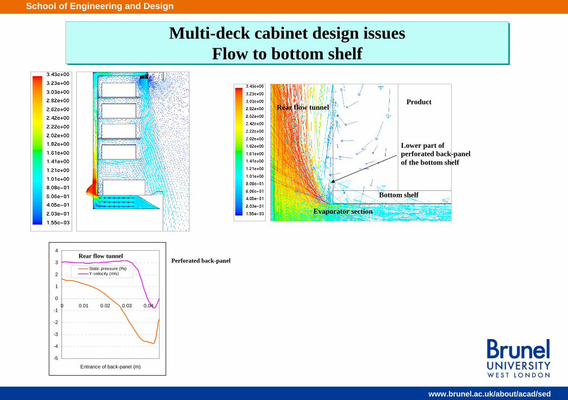
Multi-deck cabinet design issues Flow to bottom shelf
Multi-deck cabinet design issues Flow to bottom shelf
-5
-4
-3
-2
-1
0
1
2
3
4
0 0.01 0.02 0.03 0.04
Entrance of back-panel (m)
Static pressure (Pa)Y-velocity (m/s)
Rear flow tunnel Perforated back-panel
Rear flow tunnel
Evaporator section
Bottom shelf
Product
Lower part of perforated back-panel of the bottom shelf

School of Engineering and Design
www.brunel.ac.uk/about/acad/sed
Multi-deck cabinet design issues Flow to bottom shelf
Multi-deck cabinet design issues Flow to bottom shelf
• Uniform flow distribution in back flow tunnel can be controlled through honeycomb or appropriate flow resistance at inlet to rear flow tunnel
Modified honeycomb (A1)
Solid plate (B1)
Case without modifications (C1)
-5
-4
-3
-2
-1
0
1
2
3
4
0 0.01 0.02 0.03 0.04
Enterance of back-panel (m)
P (pa) (Case A1) V (m/s) (Case A1)
P (pa) (Case B1) V (m/s) (Case B1)
P (pa) (Case C1) V (m/s) (Case C1)

School of Engineering and Design
www.brunel.ac.uk/about/acad/sed
Energy Saving Potetntial
ECM motors 67% more efficient-Tangential fans -Variable speed?More efficient coilMore efficient lighting –LEDs – 66% savings
Energy savings ~ 30%
Air curtain Significant potential
Night blinds Savings ~ 20%
75%
6%
6%
8% 4%1% Infiltration
Radiation
Conduction
Lighting
EvaporatorfansDefrost
TOTAL = 1885 Watts
Contributions to load of open vertical multi-deck cabinets
School of Engineering and Design
www.brunel.ac.uk/about/acad/sed
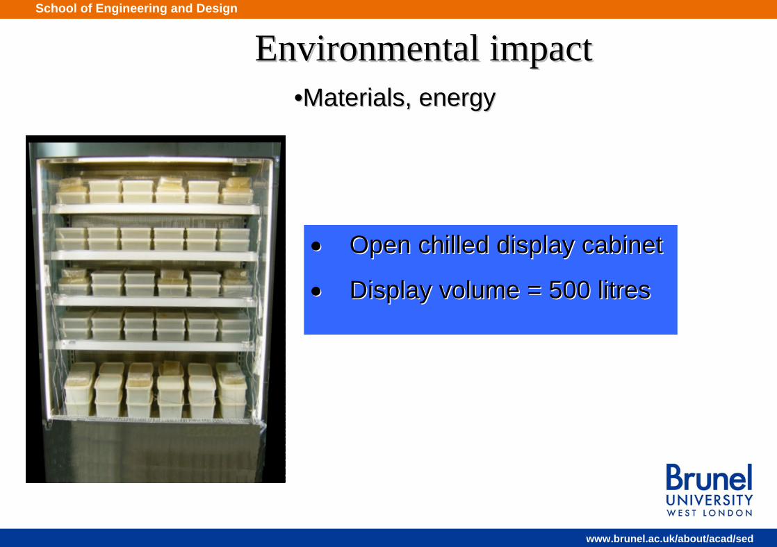
••Materials, energyMaterials, energy
Environmental impactEnvironmental impact
•• Open chilled display cabinetOpen chilled display cabinet
•• Display volume = 500 litresDisplay volume = 500 litres

School of Engineering and Design
www.brunel.ac.uk/about/acad/sed
Environmental impact Environmental impact -- InventoryInventory
Mild steel21%
Glass8%
Chipboard30%
Stainless steel30%
Foam PlasticsRefrigerant
CopperAluminium Stainless steel
ChipboardMild steelGlassCopperAluminiumFoamPlasticsRefrigerant
Total mass = Total mass = 234 kg234 kg
School of Engineering and Design
www.brunel.ac.uk/about/acad/sed
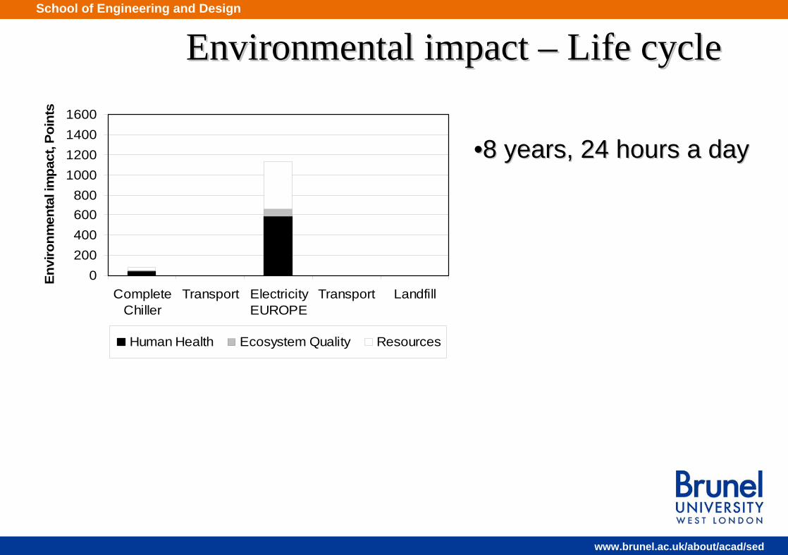
Environmental impact Environmental impact –– Life cycleLife cycle
0200400600800
1000120014001600
CompleteChiller
Transport ElectricityEUROPE
Transport Landfill
Envi
ronm
enta
l im
pact
, Poi
nts
Human Health Ecosystem Quality Resources
••8 years, 24 hours a day8 years, 24 hours a day
School of Engineering and Design
www.brunel.ac.uk/about/acad/sed
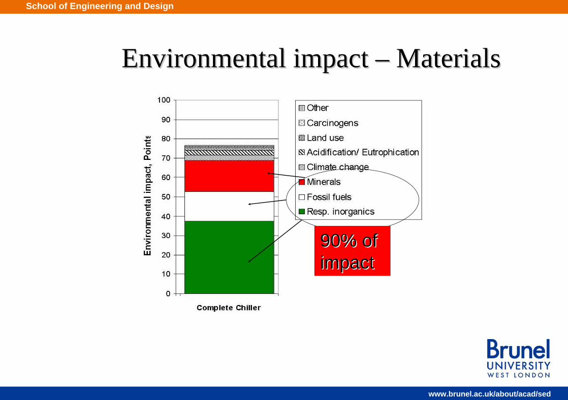
Environmental impact Environmental impact –– MaterialsMaterials
90% of 90% of impactimpact

School of Engineering and Design
www.brunel.ac.uk/about/acad/sed
Environmental impact Environmental impact –– MaterialsMaterials
0 5 10 15 20 25 30
Nickel
Copper
Energy US
Steel
Heat diesel
Energy Asia
Glass (white)
Aluminium ingots
PE (LDPE)
Crude oil
Remaining processes
Environmental impact, Points
52% of 52% of impactimpact

School of Engineering and Design
www.brunel.ac.uk/about/acad/sed
Reducing impact Reducing impact –– MaterialsMaterials•• Copper and Nickel have similar Copper and Nickel have similar
contributionscontributions
•• Nickel (in stainless steel) can be Nickel (in stainless steel) can be avoided by using 430 stainless avoided by using 430 stainless steel instead of 304steel instead of 304
•• Reduces the Reduces the chiller’schiller’senvironmental impact from environmental impact from materials by 30%.materials by 30%.
School of Engineering and Design
www.brunel.ac.uk/about/acad/sed
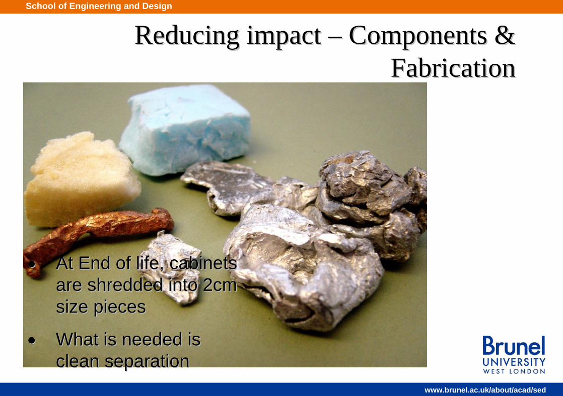
Reducing impact Reducing impact –– Components & Components & FabricationFabrication
•• At End of life, cabinets At End of life, cabinets are shredded into 2cm are shredded into 2cm size piecessize pieces
•• What is needed is What is needed is clean separationclean separation

School of Engineering and Design
www.brunel.ac.uk/about/acad/sed
•• Minimize number of materialsMinimize number of materials
•• Low use of plasticsLow use of plastics
•• Use of wood with low embodied energyUse of wood with low embodied energy
•• Flat sheet insulation with minimum bondingFlat sheet insulation with minimum bonding
•• KeyKey--hole drophole drop--on fixings or screws, rather than on fixings or screws, rather than rivets or spotrivets or spot--weldingwelding
•• Electrical distribution & components Electrical distribution & components concentrated in one accessible compartmentconcentrated in one accessible compartment
Reducing impact Reducing impact –– Components & Components & FabricationFabrication
GOOD DESIGN FEATURES:GOOD DESIGN FEATURES:

School of Engineering and Design
www.brunel.ac.uk/about/acad/sed
Simulation of supermarket zone - aisleSimulation of supermarket zone - aisle
Free boundary
X
L
X
Y
Y
1000
1000
W
Free boundary
Symmetrical surface
H

School of Engineering and Design
www.brunel.ac.uk/about/acad/sed
No heating system in zoneNo heating system in zone
Section A
Section B
Section C
Section D
2m
2m
2m
Section A Section B
Section C Section D
1100mm1350mm
1600mm 1650mm
School of Engineering and Design
www.brunel.ac.uk/about/acad/sed
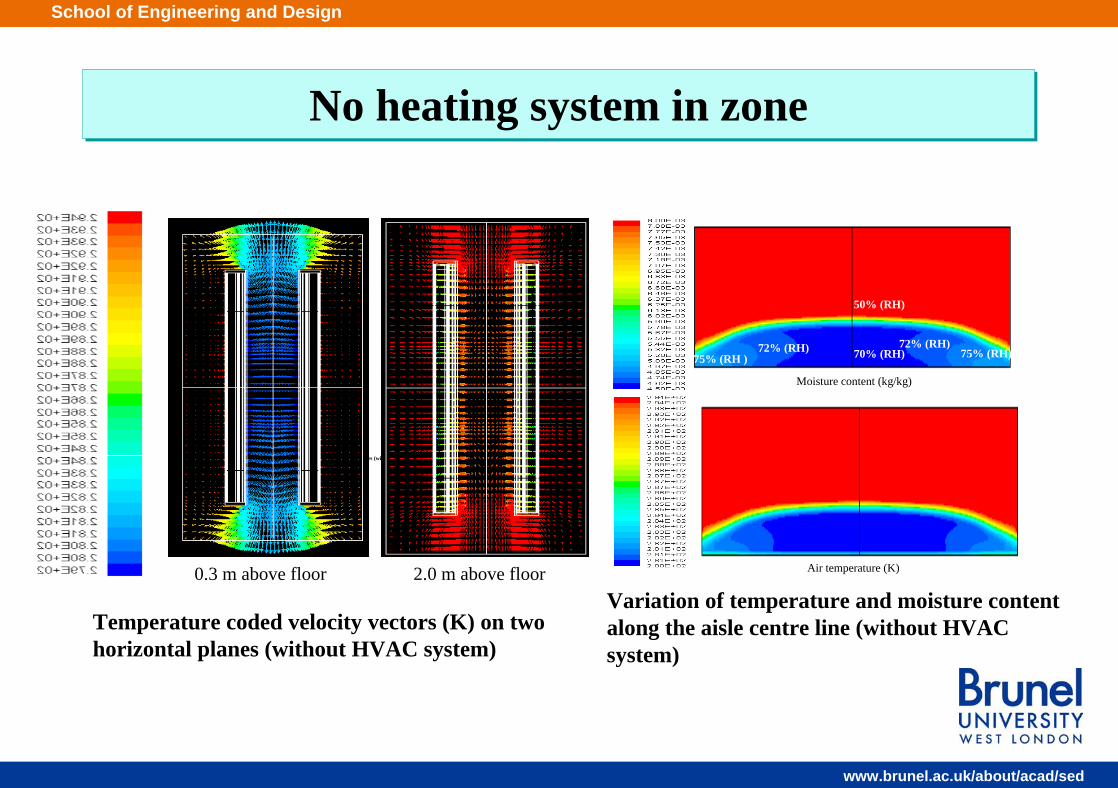
No heating system in zoneNo heating system in zone
Temperature coded velocity vectors (K) on two horizontal planes (without HVAC system)
Moisture content (kg/kg)
Air temperature (K)
70% (RH)
50% (RH)
72% (RH) 72% (RH)75% (RH ) 75% (RH)
0.3 m above floor 2.0 m above floorVariation of temperature and moisture content along the aisle centre line (without HVAC system)
Temperature coded velocity vectors (K) on two horizontal planes (without HVAC system)

School of Engineering and Design
www.brunel.ac.uk/about/acad/sed
Under floor heating systemUnder floor heating system
2.5 m
Section A
Section B
Section C
Section D 12 m
2m
2m
2m
Temperature contours (K) on a horizontal plane 0.3 m above floor level
Section A Section B
Section C Section D
Temperature contours (K) at different sections (floor heating system)
Product temperature (°C) Heating power (W/m2)
Cooling load
(kW/m) Top shelf 3rd shelf Bottom shelf
Minimum temperature in
zone (°C) 0 (No HVAC) 0.91 3.1 2.1 3.8 7.5
150 0.93 3.7 2.5 4.7 9.0 200 0.96 3.9 2.6 4.9 9.5

School of Engineering and Design
www.brunel.ac.uk/about/acad/sed
Top extract and bottom supplyTop extract and bottom supply
0.1 m 3/s/m
Heat from main refrigeration. rack
Dehumidifying cooling coil
Evaporator
0.1 m3/s/m
0.1 m 3/s/m
Heat from main refrigeration. rack
Dehumidifying cooling coil
Evaporator
12 m
2.5m
Section A
Section B
Section C
Section D
2m
2m
2m
Product temperature (°C) Bottom supply temperature (°C)
Cooling load
(kW/m) Top shelf 3rd shelf Bottom shelf
Minimum temperature in
zone (°C) No heating system 0.91 3.1 2.1 3.8 7.5
21 0.82 3.3 2.2 4.2 10 25 0.84 3.5 2.4 4.4 11
Temperature contours (K) on a plane 0.3 m above floor level (top suction and bottom supply system)
School of Engineering and Design
www.brunel.ac.uk/about/acad/sed
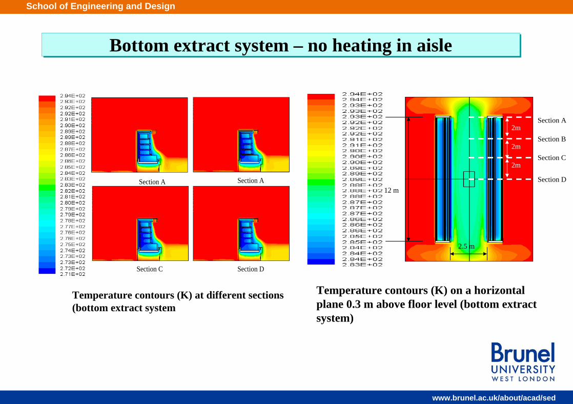
Bottom extract system – no heating in aisleBottom extract system – no heating in aisle
Section A Section A
Section C Section D
12 m
2.5 m
Section A
Section B
Section C
Section D
2m
2m
2m
Temperature contours (K) at different sections (bottom extract system
Temperature contours (K) on a horizontal plane 0.3 m above floor level (bottom extractsystem)
School of Engineering and Design
www.brunel.ac.uk/about/acad/sed
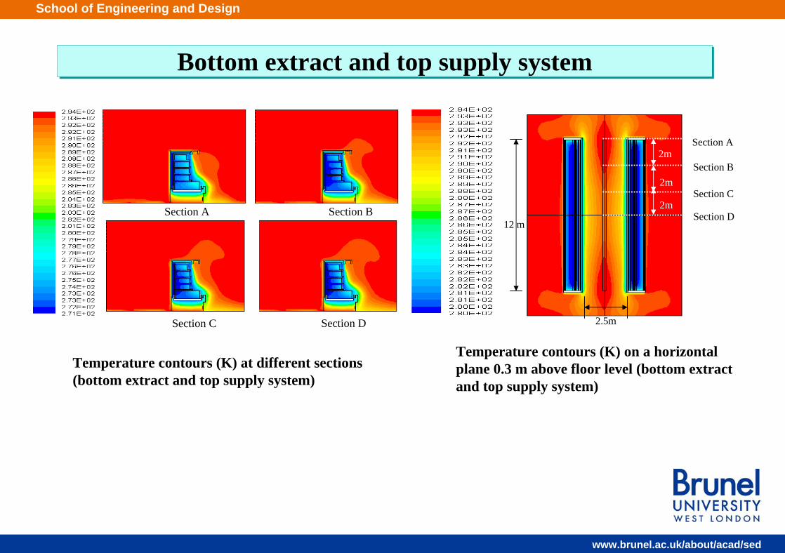
Bottom extract and top supply system Bottom extract and top supply system
Section A Section B
Section C Section D
2m
2m
2m
Section A
Section B
Section C
Section D
2.5m
12 m
Temperature contours (K) on a horizontal plane 0.3 m above floor level (bottom extractand top supply system)
Temperature contours (K) at different sections (bottom extract and top supply system)
School of Engineering and Design
www.brunel.ac.uk/about/acad/sed
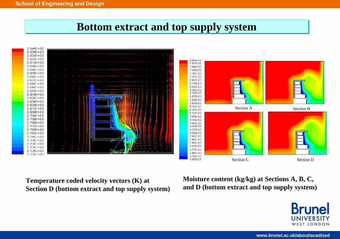
Bottom extract and top supply system Bottom extract and top supply system
Section A Section B
Section C Section D
Moisture content (kg/kg) at Sections A, B, C, and D (bottom extract and top supply system)
Temperature coded velocity vectors (K) at Section D (bottom extract and top supply system)

School of Engineering and Design
www.brunel.ac.uk/about/acad/sed
Comparison of different systemsComparison of different systems
Zone type Latent cooling load (kW/m)
Total cooling load (kW/m)
No HVAC 0.28 0.91
Top extract and bottom supply 0.24 0.82
Bottom extract and top supply 0.16 0.84
Zone type Temperature
Top shelf (ºC)
Temperature 3rd shelf
(ºC)
TemperatureBottom shelf
(ºC)
Zone minimum air temperature
(ºC) Bottom extract 3.6 2.4 4.7 13 Bottom extract and top supply 3.7 2.4 4.7 17
No HVAC system 3.1 2.1 3.8 7.5
Latent and total cooling load for different systems
Comparison between bottom extract system, bottom extract and topsupply systems and no HVAC system
School of Engineering and Design
www.brunel.ac.uk/about/acad/sed
SummarySummary
• Progress has been made but further work needs to be done to gain an in-depth understanding of the factors influencing the performance of air curtains in display cabinets.
• Becoming more important with the use of higher opening heights.• Evaluation of performance of ECM fans and LED lighting in field
trials.• Control integration and system optimisation in real time.• Compact and efficient evaporator/cooling coil designs to minimise
material use and frosting/defrosting losses.• Impact of merchandising approaches on cabinet design, sales and
energy use