BROOKHWEN - bnl.gov
7
-/ ,’ - BROOKHWEN NATI 0NpA”L LAB 0 RAT0 RY J BNL-74984-2005-CP An Upgrade of Magnet-Field-Driven Timing Systems at the AGS Y. Tian, B. Oerter Submitted to I Oth International Conference on Accelerator and Large Experimental Physics Control Systems (ICLEPCS) 200.5, Geneva, Switzerland, October 1044, 2005 September, 2005 Collider-Accelerator Department Brookhaven National Laboratory P.O. Box 5000 Upton, NY 1 1973-5000 www.bnl.gov Managed by Brookhaven Science Associates, LLC for the United States Department of Energy under Contract No. DE-AC02-98CHlO886 This is a preprint of a paper intendedfor publication in a journal or proceedings. Since changes may be made before publication,this preprint is made available with the understandingthat it will not be cited or reproducedwithout the permission of the author.
Transcript of BROOKHWEN - bnl.gov
- /
,’ - BROOKHWEN
NATI 0NpA”L LAB 0 RAT0 RY J
BNL-74984-2005-CP
An Upgrade of Magnet-Field-Driven Timing Systems at the AGS
Y. Tian, B. Oerter
Submitted to I Oth International Conference on Accelerator and Large Experimental Physics Control Systems (ICLEPCS) 200.5, Geneva, Switzerland, October 1044, 2005
September, 2005
Collider-Accelerator Department
Brookhaven National Laboratory P.O. Box 5000
Upton, NY 1 1973-5000 www.bnl.gov
Managed by Brookhaven Science Associates, LLC
for the United States Department of Energy under Contract No. DE-AC02-98CHlO886
This is a preprint of a paper intended for publication in a journal or proceedings. Since changes may be made before publication, this preprint is made available with the understanding that it will not be cited or reproduced without the permission of the author.
DISCLAIMER
This report was prepared as an account of work sponsored by an agency of the United States Government. Neither the United States Government nor any agency thereof, nor any Qf their employees, nor any of their contractors, subcontractors, or their employees, makes any warranty, express or implied, or assumes any legal liability or responsibility for the accuracy, completeness, or any third party’s use or the results of such use of any information, apparatus, product, or process disclosed, or represents that its use would not infinge privately owned rights. Reference herein to any specific commercial product, process, or service by trade name, trademark, manufacturer, or otherwise, does not necessarily constitute or imply its endorsement, recommendation, or favoring by the United States Government or any agency thereof or its contractors or subcontractors. The views and opinions of authors expressed herein do not necessarily state or reflect those of the United States Government or any agency thereof
AN UPGRADE OF MAGNET-FIELD-DRIVEN
TIMING SYSTEMS AT THE AGS
Y. Tian, E. Oerter
Brookhaven National hboratov , Upton, New York 11973, USA
ABSTRACT An upgrade of the main magnet-field-driven timing systems at Brookhaven National Laboratory's
Alternating Gradient Synchrotron (AGS) and Booster accelerators will be described in this paper. A novel approach using content addressable memory (CAM) is applied to overcome a weakness in the previous systems, which required a reproducible dwell field for proper operation. Upgraded from a multibus-based system to a VME-based system, the new timing system also proves easier to maintain and to diagnose. Details of the system architecture, as well as its application in other timing systems will be discussed.
INTRODUCTION A Timing system is typically required in an accelerator to synchronize all the components in the
accelerator complex [l]. The task of the main magnet-field-driven timing system at Brookhaven National Laboratory's Alternating Gradient Synchrotron (AGS) accelerator is to'generate 8-bit timing events at scheduled magnetic fields. These timing events are broadcasted to various accelerator equipment systems to control and synchronize their activities. In a magnet-field-driven timing system, a table is used to define the output event codes at specific
magnetic fields. The table is loaded before the start of an accelerator cycle. Once the cycle starts, the timing system follows the accelerators magnetic field and searches in its table to find if the field exists. If a match is found, the corresponding event code will be generated. In the previous timing system, a pointer-based searching algorithm was used to find the match of a
magnetic field. This approach required a good initial magnetic field, i.e., a reproducible dwell field, for proper operation. A shift of the dwell field could halt the search operation and therefore stop the timing system. Some adjustments were needed to restart the system. During our previous operations, such a situation occurred occasionally. To overcome this weakness, a novel approach using content addressable memory (CAM) was applied
to replace the point-based table-searching algorithm. The CAM-based algorithm is able to quickly search the entire table and is not dependent on the reproducibility of the dwell field. Therefore the drift of the dwell field doesn't affect'the performance of the timing system. CAM-based timing systems have been implemented in the AGS accelerator for more than one year and have been running smoothly. In addition, the CAM-based timing system is a standard VME-based system and is easier to maintain and to diagnose than the previous multibus-based system. We have also applied the CAM- based design to upgrade the 6QHZ-clock-driven and 1MHZ-clock-driven timing systems at the AGS accelerator. Similar upgrades have been done at Brookhaven National Laboratory's Booster accelerator.
SYSTEM ARCHITECTURE Multibus-based timing system The architecture of the multibus-based timing system is shown in Figure 1. There are four pre-
defined tables. Each table represents a different accelerator timing cycle and can be individually loaded before the accelerator cycle starts. A table consists of up to two thousand scheduled entries. Each entry has a 24-bit setpoint and an 8-bit event code. The setpoint is the scheduled magnetic field value at which an event code should be generated. The setpoint least count represents 0.2 Gauss and 0.1 Gauss for the AGS and Booster accelerators respectively. *
Work performed under the auspices of the. US. Department of Energy.
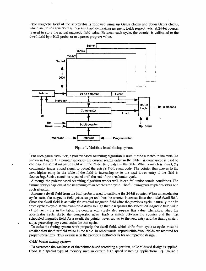
The magnetic field of the accelerator is followed using up Gauss clocks and down Gauss clocks, which are pulses generated in increasing and decreasing magnetic fields respectively. A 24-bit counter is used to store the actual magnetic field value. Between each cycle, the counter is calibrated to the dwell field by a Hall probe, or to a preset program value.
Table1
t + 2000
Table21 -~ ~
24 bit setpoint I Event I I
Table4
Table3
I . I I
lncrldecr
Comparator
TO A cl" I-:. .. .ounter I
t Hall probe Program value
Figure 1. Multibus-based timing system
t f Up Down
For each gauss clock tick, a pointer-based searching algorithm is used to find a match in the table. As shown in Figure 1, a pointer indicates the current search entry in the table. A comparator is used to
comparator issues a load signal to output the entry's 8-bit event code. The pointer then moves to the next higher entry in the table if the field is increasing or to the next lower entry if the field is decreasing. Such a search is repeated until the end of the accelerator cycle. Although the pointer-based searching algorithm works well, it can fail under certain conditions. The
failure always happens at the beginning of an accelerator cycle. The following paragraph describes one such situation. Assume a dwell field from the Hall probe is used to calibrate the 24-bit counter. When an accelerator
cycle starts, the magnetic field gets stronger and thus the counter increases from the initial dwell field. Since the dwell field is actually the residual magnetic field after the previous cycle, naturally it drifts from cycle to cycle. If the dwell field drifts so high that it surpasses the scheduled magnetic field value of the first entry in the table, the counter will surely also surpass this value. Therefore, when the accelerator cycle starts, the comparator never finds a match between the counter and the first scheduled'magnetic field. As a result, the pointer never moves to the next entry and the timing system stops generating any event codes for that cycle. To make the timing system work properly, the dwell field, which drifts from cycle to cycle, must be
smaller than the first field value in the table. In other words, reproducible dwell fields are required for proper operations. This weakness in the previous method calls for an improved design.
L compare the actual magnetic field with the 24-bit field value in the table. When a match is found, the
CAM-based timing system To overcome the weakness of the pointer-based searching algorithm, a CAM-based design is applied.
CAM is a special type of memory used in certain high speed searching applications [2]. Unlike a
standard memory, which returns the saved data for a supplied address, a CAM is designed such that data is supplied and the CAM searches its entire memory to see if the data is stored anywhere in it. If the data is found, the CAM returns a list of one or more memory addresses where the word is found. Since a CAM is designed to quickly search its entire memory, it is much faster than a standard memory in virtually all searching applications. A typical application of CAM is in the design of communication router that can quickly search through its routing table to find a port for each IP packet, and that can also update its routing table rapidly.
Table8 I Table7 1
Table6 I Table5 I
Table4 I Table3 I
Table2 I - -
24 bit counter o:zn
Table1 -
Hall probe Program value
d
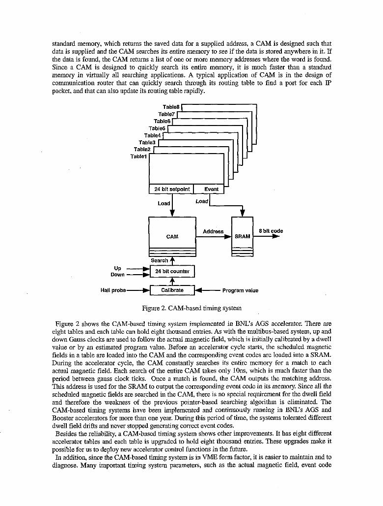
Figure 2. CAM-based timing system
-
Figure 2 shows the CAM-based timing system implemented in BNL's AGS accelerator. There are eight tables and each table can hold eight thousand entries. As with the multibus-based system, up and down Gauss clocks are used to follow the actual magnetic field, which is initially calibrated by a dwell value or by an estimated program value. Before an accelerator cycle starts, the scheduled magnetic fields in a table are loaded into the CAM and the corresponding event codes are loaded into a SRAM. During the accelerator cycle, the CAM constantly searches its entire memory for a match to each actual magnetic field. Each search of the entire CAM takes only lOns, which is much faster than the period between gauss clock ticks. Once a match is found, the CAM outputs the matching address. This address is used for the SIgAM to output the corresponding event code in its memory. Since all the scheduled magnetic fields are searched in the CAM, there is no special requirement for the dwell field and therefore the weakness of the previous pointer-based searching algorithm is eliminated. The CAM-based timing systems have been implemented and continuously running in BNL's AGS and Booster accelerators for more than one year. During this period of time, the systems tolerated different dwell field drifts and never stopped generating correct event codes. Besides the reliability, a CAM-based timing system shows other improvements. It has eight different
accelerator tables and each table is upgraded to hold eight thousand entries. These upgrades make it possible for us to deploy new accelerator control functions in the future. In addition, since the CAM-based timing system is in VME form factor, it is easier to maintain and to
diagnose. Many important timing system parameters, such as the actual magnetic field, event code
24 bit setpoint I Event -
CAM Address 8 bit code
SRAM
I
output, table information and dwell value, can be easily read back from the new module. Also abnormal conditions can be detected and handled through standard VME interrupt mechanisms.
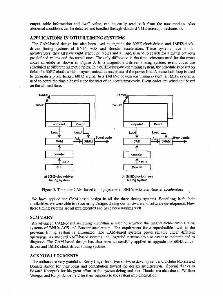
APPLICATIONS IN OTHER TIMING SYSTEMS The CAM-based design has dso been used to upgrade the 6OHZ-clock-driven and 1MHZ-clock-
driven timing systems of B W s AGS and Booster accelerators. These systems have similar architectures: they all have eight scheduled tables and a CAM is used to search for a match between pre-defined values and the actual ones. The only difference is the time reference used for the event codes schedule as shown in Figure 3. In a magnet-field-driven timing system, event codes are scheduled at different magnetic fields. In a 6OHZ-clock-driven timing system, the schedule is based on ticks of a 60HZ clock, which is synchronized to one phase of the power line. A phase lock loop is used to generate a phase-locked 6 0 l Z signal. In a 1MHZ-clock-driven timing system, a lMHZ crystal is used to count the time elapsed since the start of an accelerator cycle. Event codes are scheduled based on the elapsed time.
I setpoint Event
Event code b
Event code SRAM
counter x I counter I 1 MHZ
I Crystal I a) GOHZ-clock-driven
timing system b) 1 MHZ-clock-driven
timing system
Figure 3. The other CAM-based timing systems in BNL's AGS and Booster accelerators
We have applied the CAM-based design in all the'three timing systems. Benefiting from their similarities, we were able to reuse many designs during our hardware and software development. Now these timing systems are all implemented and have been running well.
SUMMARY An advanced CAM-based searching algorithm is used to upgrade the magnet-field-driven timing
systems of BNL's AGS and Booster accelerators. The requirement for a reproducible dwell in the previous timing system is eliminated. The CAM-based systems prove reliable under different operations. As standard VME-based systems, the upgraded systems are also easier to maintain and to diagnose. The CAM-based design has also been successfully applied to upgrade the 6OHZ-clock- driven and 1MHZ-clock-driven timing systems.
ACKNOWLEDGMENTS The authors are very grateful to Kerry Unger for driver software development and to John Morris and
Donald Barton for their ideas and contribution toward the design specification. Special thanks to Edward Koropsak for his great effort to the system debug and test: Thanks are also due to William Venegas and Ralph Schoenfeld for their supports to the system implementation.

REFERENCE [ 13 “Review of Accelerator Timing System”, T. Korhonen, Paul Scherrer Institut, Switzerland
International Conference on Accelerator and Large Experimental Physics Control Systems (ICALEPCS), 1999, Trieste, Italy
[2] “SiberCAM Ultra-2M SCT2OOOC Large-capacity Content‘ Addressable Memory Data Sheet”, May 5,2002, SiberCore Technologies, http://www.sibercore.com