Broadcast Products Technical Bulletin 20-2012-119 · 2012-12-15 · B-HDCM11-038R-0.FM Broadcast...
22
Page 1 of 22 B-HDCM11-038R-0.FM Broadcast Products Technical Bulletin 20-2012-119 Master Setup Unit DATE: December 10, 2012 DESCRIPTION Firmware version 2.00 is available. ORDERING INFORMATION To order upgrades, contact: Sony SoftwarePLUS ® (800) 538-7550 www.sony.com/softwareplus Customers outside the United States: Please order parts or upgrades from your usual supplier. NOTE: • The firmware is available by download only from the SoftwarePLUS website above • For upgrade instructions see “FIRMWARE UPDATE” on page 16. SUMMARY OF NEW FUNCTIONS • New functions for HDC2000 and HDCU2000 are supported. Refer to “SUPPORT FOR HDC2000 AND HDCU2000” on page 2. • Specifications for control of the detail knob are changed. Refer to “DETAIL KNOB” on page 7. • The RCP Assignment file operation is supported. Refer to “RCP ASSIGNMENT FILE OPERATION” on page 8. • A specification is added to force availability of PANEL ACTIVE. Refer to “FORCED AVAILABILITY OF PANEL ACTIVE” on page 12. • SELF-LOCK mode is added to PANEL ACTIVE mode. Refer to “SELF-LOCK MODE” on page 12. • Specifications are changed for panel setting backup files (Network Config, Custom Paint Menu, Custom Assign). Refer to “PANEL SETTING BACKUP FILES” on page 13. • The character entry screen is changed to keyboard style. Refer to “KEYBOARD STYLE CHARACTER ENTRY” on page 15. FIRMWARE REQUIRED Part No. Description Qty. MMSU10005 MSU-1000/1500 Firmware V2.00 1 Broadcast Products Technical Bulletin 20-2012-119 SUBJECT: FIRMWARE UPGRADE—VERSION 2.00 HDCM11-038R MODEL: MSU-1000 MSU-1500 SERIAL NO: MSU-1000 110,001–110,050 110,001–110,050 MSU-1500 100,001–100,192 110,001–110,070
Transcript of Broadcast Products Technical Bulletin 20-2012-119 · 2012-12-15 · B-HDCM11-038R-0.FM Broadcast...

Page 1 of 22B-HDCM11-038R-0.FM Broadcast Products Technical Bulletin 20-2012-119
Master Setup Unit
DATE: December 10, 2012
DESCRIPTION
Firmware version 2.00 is available.
ORDERING INFORMATION
To order upgrades, contact:
Sony SoftwarePLUS®
(800) 538-7550www.sony.com/softwareplus
Customers outside the United States: Please order parts or upgrades from your usual supplier.
NOTE:
• The firmware is available by download only from the SoftwarePLUS website above
• For upgrade instructions see “FIRMWARE UPDATE” on page 16.
SUMMARY OF NEW FUNCTIONS
• New functions for HDC2000 and HDCU2000 are supported. Refer to “SUPPORT FOR HDC2000 AND HDCU2000” on page 2.
• Specifications for control of the detail knob are changed. Refer to “DETAIL KNOB” on page 7.
• The RCP Assignment file operation is supported. Refer to “RCP ASSIGNMENT FILE OPERATION” on page 8.
• A specification is added to force availability of PANEL ACTIVE. Refer to “FORCED AVAILABILITY OF PANEL ACTIVE” on page 12.
• SELF-LOCK mode is added to PANEL ACTIVE mode. Refer to “SELF-LOCK MODE” on page 12.
• Specifications are changed for panel setting backup files (Network Config, Custom Paint Menu, Custom Assign). Refer to “PANEL SETTING BACKUP FILES” on page 13.
• The character entry screen is changed to keyboard style. Refer to “KEYBOARD STYLE CHARACTER ENTRY” on page 15.
FIRMWARE REQUIRED
Part No. Description Qty.
MMSU10005 MSU-1000/1500 Firmware V2.00 1
Broadcast ProductsTechnical Bulletin 20-2012-119
SUBJECT: FIRMWARE UPGRADE—VERSION 2.00
HDCM11-038R
MODEL: MSU-1000MSU-1500
SERIAL NO:
MSU-1000 110,001–110,050
110,001–110,050
MSU-1500 100,001–100,192
110,001–110,070

Page 2 of 22B-HDCM11-038R-0.FM Broadcast Products Technical Bulletin 20-2012-119
SUPPORT FOR HDC2000 AND HDCU2000
Adaptive Matrix and Natural Skin Detail
The following new functions of HDC2000 and HDCU2000 are supported:
• Adaptive Matrix
Paint > Matrix > Adaptive Matrix > ON/OFF (See Figure 1.)
Figure 1
The Adaptive Matrix button is added to tabs:
User 1, User 2, Multi, PresetThe Adaptive Matrix function is commonly available for all Matrix functions.
• Natural Skin Detail
Paint > Skin Detail > Natural Skin DTL > ON/OFF (See Figure 2.)
Figure 2
The Natural Skin DTL button is added to tabs:
Skin DTL1, Skin DTL2, Skin DTL3The Natural Skin Detail function is commonly available for all Skin Detail functions.

Page 3 of 22B-HDCM11-038R-0.FM Broadcast Products Technical Bulletin 20-2012-119
Transfer of User Gamma Files
A function is added to transfer user gamma files from the panel to the camera similarly to transferring scene files.
File > User Gamma > User Gam Transfer
The name of the User Gamma file is indicated.(See Figure 3.)
Figure 3
Menu Submenu Control Item Function
User Gamma
User GamTransfer
MS > CAM Transfers user gamma file from Memory Stick Duo to camera.
MS > CAMsTransfers user gamma file from Memory Stick Duo to multiple cameras. Not available during network connections.
Delete Deletes user gamma file from Memory Stick Duo.
Adjusting (Paint menu items) Selects Gamma Table.
Page 4 of 22B-HDCM11-038R-0.FM Broadcast Products Technical Bulletin 20-2012-119
Gamma Table Name
A function is added to indicate the name of the gamma table.
Paint > Gamma Table (See Figure 4.)
NOTE: When Standard is selected, the name of the Gamma Table is not indicated.
Figure 4

Page 5 of 22B-HDCM11-038R-0.FM Broadcast Products Technical Bulletin 20-2012-119
Camera Menu Control from Panel
A menu is added to control the camera menu of the camera/CCU system from the panel.
Config > Camera > CAM Menu Control(See Figure 5.)
Figure 5
Menu Submenu Switch Control Item Description
Gamma Table Selects curve for gamma correction.
Standard Standard Uses standard gamma curve.
Standard Selects type of standard gamma curve.
Gamma OFF Disables gamma correction.
Hyper HyperUses gamma to reproduce dynamic range of camera including high-luminance parts.
Hyper Selects type of hyper gamma curve.
Gamma OFF Disables gamma correction.
Special Special Selects gamma that emulates film and other gamma.
Special Selects type of special gamma curve.
Gamma OFF Disables gamma correction.
User User Selects gamma created with CVP File Editor and other gamma.
User Selects type of user gamma curve.
Gamma OFF Disables gamma correction.

Page 6 of 22B-HDCM11-038R-0.FM Broadcast Products Technical Bulletin 20-2012-119
The Menu Overlay button switches CCU menu indication to camera menu indication to enable operation of the camera menu by confirming the menu on CCU output.
NOTE: Items currently located in Config > Camera are moved to Config > Camera > Mode.
Operation
• Use CAM Menu Overlay to display the camera menu, switching from the CCU character display (PIX OUT). The following operations are not available when CAM Menu Overlay is ON.
• To turn ON the camera menu display with the Menu button:
• Use Display to display or hide camera operation mode.• Use Menu to display or hide the camera menu.• Display and Menu buttons are equivalent to the toggle
switch for the menu display in the camera head.• To operate while displaying the camera menu:
• Press Enter to switch to setting mode and confirm the setting change.
• Press Cancel to end setting mode and cancel the setting change.
• Turn the adjustment knob on the right to move the cursor in the camera menu and change the setting.
Menu Submenu Item Option Function
Camera
Mode
CAM Menu Control — Control Camera VF menu.

Page 7 of 22B-HDCM11-038R-0.FM Broadcast Products Technical Bulletin 20-2012-119
DETAIL KNOB
Specifications for Control of SD Detail
When the SD detail control function is assigned to the detail knob, and the panel is connected directly to a camera in stand-alone mode, the control command for the down converter of the camera is now sent.
Maintenance > SD Adjusting > SD Detail
Menu Secondary Menu Submenu Switch Control Item Description
SD Adj Maintenance items for down converter output
SD Detail Contour correction function for down converter output
OFF Disables SD Detail function.
1/3 First page of SD Detail adjustment
LevelContour correction levelAdjusting in plus direction sharpens picture; adjusting in minus direction softens picture.
Limiter
Makes adjustments so contour correction is not greater than a set level to prevent over correction by strong contour correction when shooting subjects with large luminance differences. Adjusting in plus direction enables clipping of objects with small luminance differences.
Crisp
Makes adjustments so signals with small luminance differences are considered noise and correction is not applied to de-emphasize contours of noise with the contour correction function. Adjusting in plus direction results in luminance differences for which contour correction is not performed, becoming large and improving S/N sensitivity, but resolution sensitivity deteriorates.
Level Dep
Contour correction is not applied to dark parts and S/N sensitivity is increased to de-emphasize contours of noise with the contour correction function.Adjusting in plus direction results in contour correction not being applied up to a brighter level.
2/3 Second page of SD Detail adjustment
H/V ratio Adjusts horizontal and vertical ratio of contour correction.
Frequency Adjusts center frequency of contour correction.
Detail Comb
Reduces cross color noise by applying comb filter to contour correction signals. Adjusting in plus direction reduces cross color noise, but resolution sensitivity deteriorates. This can only be used when an SD camera is connected.
3/3 Third page of SD Detail adjustment
W Limiter Limiter correction for detail signals added in white direction.
B Limiter Limiter correction for detail signals added in black direction.

Page 8 of 22B-HDCM11-038R-0.FM Broadcast Products Technical Bulletin 20-2012-119
RCP ASSIGNMENT FILE OPERATION
RCP Assignment file operation is supported. Up to five settings for RCP assignment can be stored and recalled in internal MSU memory.
Config > RCP Assignment(See Figure 6.)
Figure 6
Menu Submenu Switch Control Item Description
RCP Assignment 1–5 Selects memory file number of
RCP Assignment.
CLR Clears memory file of selected RCP Assignment.
Store Saves memory file of RCP Assignment.
RCP List Sets RCP Assignment setting.
Panel Selects panel to change RCP Assignment.
Camera Selects camera to be assigned to selected panel.
Set Enables reflection of state of RCP List to system.
Cancel Returns state of RCP List to current state.
All Camera
Displays panel and camera that are currently not in system in RCP List.
All Reset
Resets current state of RCP Assignment.

Page 9 of 22B-HDCM11-038R-0.FM Broadcast Products Technical Bulletin 20-2012-119
To Recall State of RCP Assignment
To recall the state of RCP Assignment from MSU internal memory:
1. Press the file operation button to select the saved state of RCP Assignment to recall. The selected file button lights, and the state of RCP assignment is reflected in the RCP List. (See Figure 7.)
NOTE: • The only file operation buttons enabled are those in which
the state of RCP assignment is saved. Before the Set button is pressed, RCP assignment is not recalled yet, and RCP assignment can be modified with panel and camera knobs.
• If the system configuration (panel, camera, and CCU) is changed from when the RCP assignment file was saved, operation of recalled assignment status is not guaranteed.
Figure 7
2. Press the Set button. The file operation button is no longer lit, and the setting is recalled.
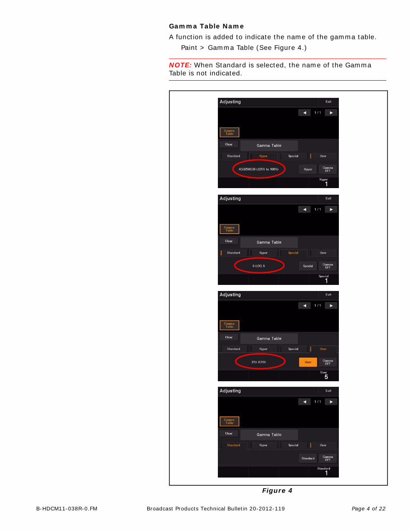
To Save State of RCP Assignment
To save the state of RCP Assignment:
1. Set the state of RCP Assignment.
2. Press the Store button. The Store button lights.(See Figure 8.)
FILE OPERATION BUTTONS FOR INTERNAL MEMORY
Page 10 of 22B-HDCM11-038R-0.FM Broadcast Products Technical Bulletin 20-2012-119
Figure 8
3. Press the file operation button to save. The state of RCP Assignment is saved to the assigned file number, and the Store file operation buttons are no longer lit.
To Clear RCP Assignment
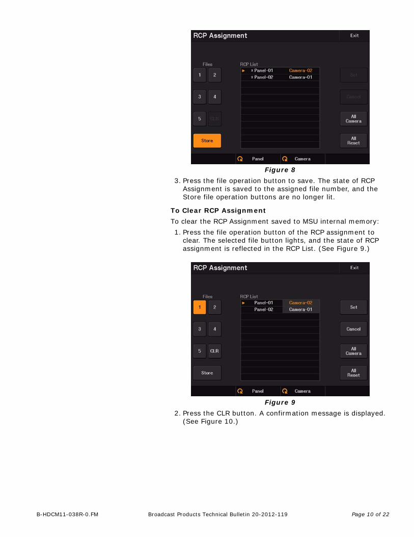
To clear the RCP Assignment saved to MSU internal memory:
1. Press the file operation button of the RCP assignment to clear. The selected file button lights, and the state of RCP assignment is reflected in the RCP List. (See Figure 9.)
Figure 9
2. Press the CLR button. A confirmation message is displayed. (See Figure 10.)
Page 11 of 22B-HDCM11-038R-0.FM Broadcast Products Technical Bulletin 20-2012-119
Figure 10
3. Press OK. Saved data of the specified file is cleared, and the file operation button is disabled.
Press Cancel to not clear the file. The RCP List returns to the state before the file numbers were pressed.
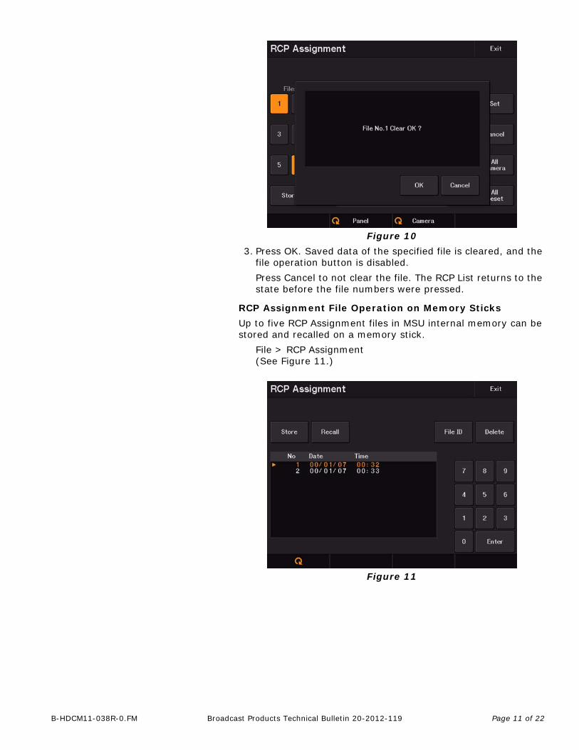
RCP Assignment File Operation on Memory Sticks
Up to five RCP Assignment files in MSU internal memory can be stored and recalled on a memory stick.
File > RCP Assignment(See Figure 11.)
Figure 11

Page 12 of 22B-HDCM11-038R-0.FM Broadcast Products Technical Bulletin 20-2012-119
FORCED AVAILABILITY OF PANEL ACTIVE
A specification is added to force availability of PANEL ACTIVE in network system emergencies when the button is not lit.
When the camera network system is configured to MCS mode, MCS master manages PANEL ACTIVE; therefore, if the HUB or MCS master unit is disrupted, the camera becomes inoperable because PANEL ACTIVE is not available. However, when the camera/CCU and panel are connected via CCA cable, communication between the panel and camera is not disrupted even if the MCS master unit or HUB is disrupted.
The forced legacy switch equipped with the CCU is provided for emergency measures against the error. This emergency function is now also provided with the panel.
Even if connection to the HUB or MCS master unit is disrupted in an MCS mode system, PANEL ACTIVE can be made available by holding the PANEL ACTIVE button for five seconds.
SELF-LOCK MODE
SELF-LOCK mode is added to the PANEL ACTIVE menu, which enables control of the applicable camera from multiple control panels (RCP/MSU) without transition of PANEL ACTIVE status between panels.
Config > MSU > Mode > Panel Active (See Figure 12.)
Figure 12
Menu Submenu Control Item Function
RCP Assignment Store/Recall Store
Saves RCP Assignment file from MSU internal memory to Memory Stick Duo.
RecallReads RCP Assignment file from Memory Stick Duo to MSU internal memory.
File ID Sets File ID in RCP Assignment file of a Memory Stick Duo.
Delete Deletes RCP Assignment file from Memory Stick Duo.
RCP Assignment — Sets RCP Assignment setting.
Page 13 of 22B-HDCM11-038R-0.FM Broadcast Products Technical Bulletin 20-2012-119
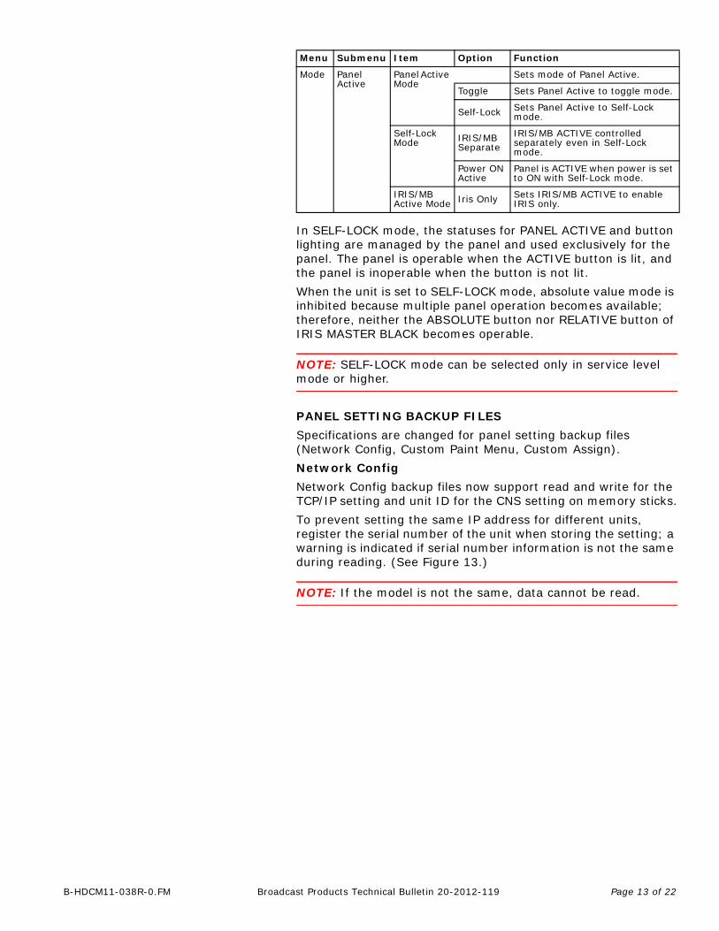
In SELF-LOCK mode, the statuses for PANEL ACTIVE and button lighting are managed by the panel and used exclusively for the panel. The panel is operable when the ACTIVE button is lit, and the panel is inoperable when the button is not lit.
When the unit is set to SELF-LOCK mode, absolute value mode is inhibited because multiple panel operation becomes available; therefore, neither the ABSOLUTE button nor RELATIVE button of IRIS MASTER BLACK becomes operable.
NOTE: SELF-LOCK mode can be selected only in service level mode or higher.
PANEL SETTING BACKUP FILES
Specifications are changed for panel setting backup files (Network Config, Custom Paint Menu, Custom Assign).
Network Config
Network Config backup files now support read and write for the TCP/IP setting and unit ID for the CNS setting on memory sticks.
To prevent setting the same IP address for different units, register the serial number of the unit when storing the setting; a warning is indicated if serial number information is not the same during reading. (See Figure 13.)
NOTE: If the model is not the same, data cannot be read.
Menu Submenu Item Option Function
Mode Panel Active
Panel Active Mode
Sets mode of Panel Active.
Toggle Sets Panel Active to toggle mode.
Self-Lock Sets Panel Active to Self-Lock mode.
Self-Lock Mode IRIS/MB
SeparateIRIS/MB ACTIVE controlled separately even in Self-Lock mode.
Power ON Active
Panel is ACTIVE when power is set to ON with Self-Lock mode.
IRIS/MB Active Mode Iris Only Sets IRIS/MB ACTIVE to enable
IRIS only.

Page 14 of 22B-HDCM11-038R-0.FM Broadcast Products Technical Bulletin 20-2012-119
Figure 13
INDICATION WHEN MODEL AND SERIAL NUMBER ARE THE SAME
INDICATION WHEN SERIAL NUMBER IS DIFFERENT

Page 15 of 22B-HDCM11-038R-0.FM Broadcast Products Technical Bulletin 20-2012-119
FILE ID for Memory Stick Files
File ID can be set or indicated for panel setting, REFERENCE, or SCENE files on the memory stick.
When the File ID in the applicable menu is pressed, a software keyboard appears for entering the File ID. (See Figure 14.)
Figure 14
KEYBOARD STYLE CHARACTER ENTRY
The character entry screen, which is used for BARS Character and Lens File Name, is changed to keyboard style for easier entry.
When pressing a button that requires character entry, such as File ID, a software keyboard appears on the screen. (See Figure 15.)
Figure 15
FILE ID INDICATION
Page 16 of 22B-HDCM11-038R-0.FM Broadcast Products Technical Bulletin 20-2012-119
FIRMWARE UPDATE
Preparation
1. Copy the firmware files to the following folder of a memory stick: \MSSONY\PRO\CAMERA\MSU1X00
2. Insert the memory stick in the memory stick slot of the unit.
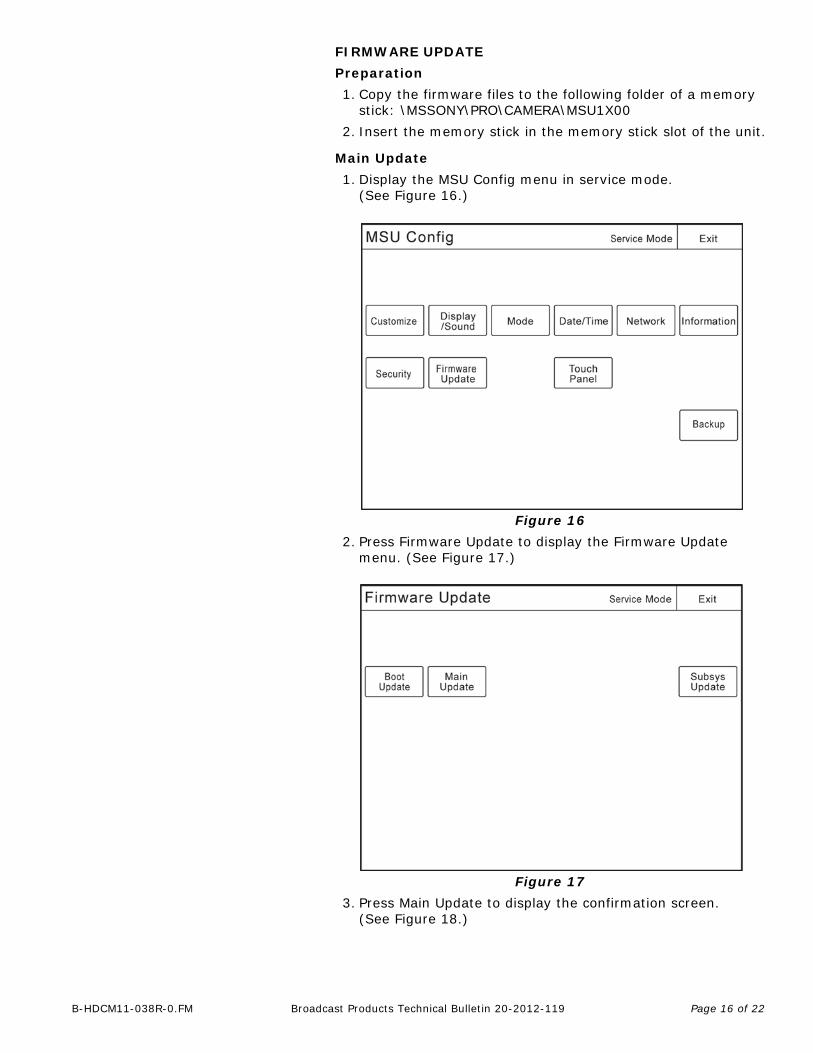
Main Update
1. Display the MSU Config menu in service mode. (See Figure 16.)
Figure 16
2. Press Firmware Update to display the Firmware Update menu. (See Figure 17.)
Figure 17
3. Press Main Update to display the confirmation screen. (See Figure 18.)

Page 17 of 22B-HDCM11-038R-0.FM Broadcast Products Technical Bulletin 20-2012-119
Figure 18
4. Press Start to update the main program.
NOTE: The Loader Section and Main Section of the main block are updated. The Loader Section is updated first. The screen is cleared when the progress bar reaches 100%, and then the Main Section is updated. (See Figure 19.)
Figure 19
Page 18 of 22B-HDCM11-038R-0.FM Broadcast Products Technical Bulletin 20-2012-119
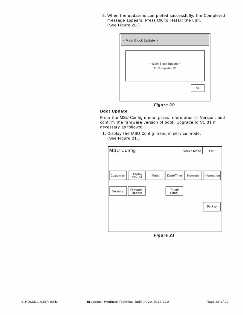
5. When the update is completed successfully, the Completed message appears. Press OK to restart the unit. (See Figure 20.)
Figure 20
Boot Update
From the MSU Config menu, press Information > Version, and confirm the firmware version of boot. Upgrade to V1.01 if necessary as follows:
1. Display the MSU Config menu in service mode. (See Figure 21.)
Figure 21

Page 19 of 22B-HDCM11-038R-0.FM Broadcast Products Technical Bulletin 20-2012-119
2. Press Firmware Update to display the Firmware Update menu. (See Figure 22.)
Figure 22
3. Press Boot Update to display the confirmation screen. (See Figure 23.)
Figure 23

Page 20 of 22B-HDCM11-038R-0.FM Broadcast Products Technical Bulletin 20-2012-119
4. Press Start to update the boot program. (See Figure 24.)
Figure 24
5. When the update is completed successfully, the Completed message appears. Press OK to restart the unit. (See Figure 25.)
Figure 25

Page 21 of 22B-HDCM11-038R-0.FM Broadcast Products Technical Bulletin 20-2012-119
Subsystem Update
From the MSU Config menu, press Information > Version, and confirm the firmware version of Subsys. Upgrade to V2.01 if necessary as follows:
1. Display the MSU Config menu in service mode. (See Figure 26.)
Figure 26
2. Press Firmware Update to display the Firmware Update menu. (See Figure 27.)
Figure 27

Page 22 of 22B-HDCM11-038R-0.FM Broadcast Products Technical Bulletin 20-2012-119
3. Press Subsys Update to display the confirmation screen. (See Figure 28.)
Figure 28
4. Press Start to update subsystem firmware.
NOTE: The illuminated switches, LEDs, and LCD are turned off during the Subsys Update, and the Memory Stick indicator displays the progress. The indicator blinks green and red during the update, and goes out upon completion of the update. After the internal data has been updated, the unit restarts automatically. DO NOT turn off power until the unit has restarted.
CONFIRMATION
From the MSU Config menu, press Information > Version, and confirm that firmware is as follows:
MAIN V2.00
BOOT V1.01
SUBSYS V2.01
Software History
MAIN BOOT SUBSYS Technical Bulletin
V1.01 V1.00 V1.01 —
V1.10 V1.01 V1.01 20-2011-053
V1.11 V1.01 V1.01 20-2011-057
V1.12 V1.01 V1.03 20-2011-061
V1.40 V1.01 V2.01 20-2011-126
V2.00 V1.01 V2.01 20-2012-119