BRL Gaskeur CV 2011 EN - Kiwa CV EN.pdf · Evaluation Guideline 1st February 2011 regarding the...
47
Evaluation Guideline 1st February 2011 regarding the Product Certificate GASKEUR Basic Label CV (Central Heating): 2010 for Central Heating Appliances
Transcript of BRL Gaskeur CV 2011 EN - Kiwa CV EN.pdf · Evaluation Guideline 1st February 2011 regarding the...

Evaluation Guideline
1st February 2011
regarding the Product Certificate GASKEUR Basic Label CV (Central Heating): 2010 for Central Heating Appliances

Preface
This Evaluation Guideline has been adopted by the Kiwa Board of Experts of Energy Performance Label, wherein all the relevant parties in the field of supply, installation and use are represented. These Boards of Experts also supervises the certification activities and where necessary require the Evaluation Guideline to be revised. All references to Board of Experts in this Evaluation Guideline pertain to the above mentioned Boards of Experts. This Evaluation Guideline will be used by Kiwa in conjunction with the Kiwa-Regulations for Product Certification. This regulation details the method employed by Kiwa for conducting the necessary investigations prior to issuing the product certificate and the method of external control. This Evaluation Guideline is drawn up for certification purposes within the framework of GASKEUR appliance labelling. This certification is voluntary and supplementary, which implies that the label is neither obligatory for admission nor permits admission in its own right. To be admitted each appliance is required by law to bear the CE Marking. GASKEUR labels are supplementary, i.e. they provide information on a certain aspect of the appliance not clearly indicated by the CE Marking. This Evaluation Guideline states the basic requirements to be met by a central heating appliance to be eligible for GASKEUR labelling. In addition to this Evaluation Guideline, there are also Evaluation Guidelines for hot water appliances and for air heaters. As supplements to the basic labels there are labels for specific appliance properties such as efficiency, comfort and emissions for which criteria exist or which will be developed. These specific labels may only be obtained if the requirements for the basic label have been met. In order to continue harmonisation with the European standards and regulations, this Evaluation Guideline uses heat inputs and efficiencies based on the net calorific value (Hi). In order to ensure complete harmonisation with national legislation, in as far as it (still) makes use of the gross value; conversion information has been included where necessary. NOTE: This is a translation from the Dutch. In case of ambiguity or differences in interpretation between this translation and the original Dutch text, the Dutch text prevails.

Evaluation Guideline GASKEUR Basic Label CV:2010 © Kiwa Nederland B.V. - 2 - 1st February 2011
Kiwa Nederland B.V. is a company with an international and independent reputation for testing and certification of gas and water related products for manufacturers and suppliers. These products include gas appliances, sanitary ware, measurement and control devices and installation and distribution materials. Kiwa Nederland B.V. also tests and certifies the raw materials for plastic pipe products. Furthermore, Kiwa Nederland B.V. certifies various quality, safety and environmental management systems for a wide range of customers. Kiwa Nederland B.V. also provides independent expertise in the form of consultancy in the field of installation safety. Kiwa Nederland B.V. is based in Apeldoorn and Rijswijk in the Netherlands and is accredited by the Dutch Council for Accreditation (RvA). Kiwa Nederland B.V. is appointed by the Dutch government as Notified Body in the field of the European Directives (CE Marking). All test work is carried out in Kiwa Nederland B.V.’s own laboratories, which are accredited to ISO/IEC 17025.
Kiwa Nederland B.V. PO Box 137, 7300 AC Apeldoorn, The Netherlands
Wilmersdorf 50,
7327 AC Apeldoorn The Netherlands
Telephone: +31(0)55 - 5 393 355 Fax: +31(0)55 - 5 393 685 E-mail: [email protected] Website: www.kiwa.nl
© 2011 Kiwa N.V. All rights reserved. No part of this book may be reproduced, stored in a database or retrieval system, or published, in any form or in any way, electronically, mechanically, by print, photoprint, microfilm or any other means without prior written permission from the publisher. The use of this Evaluation Guideline by third parties, for any purpose whatsoever, is only allowed after a written agreement is made with Kiwa to this end. Validation This Evaluation Guideline has been adopted by the Boards of Experts on 1st December 2010. This Evaluation Guideline has been declared binding by Kiwa Nederland BV on 1st Februari 2011.

Evaluation Guideline GASKEUR Basic Label CV:2010 © Kiwa Nederland B.V. - 3 - 1st February 2011
Contents Preface 1
Contents 3
1 Introduction 6 1.1 General 6 1.2 Field of Application / Scope 6 1.3 Acceptance of Test Reports Provided by the Supplier 6 1.4 Certificate 6
2 Terms and Definitions 7 2.1 General Definitions 7 2.2 Technical Definitions 8
3 Procedure for Granting the Quality Declaration 10 3.1 Pre Certification Tests 10 3.2 Granting the Certificate 10
4 General and Constructional Requirements 11 4.1 General 11 4.2 Nuisance 11 4.3 Appliance Category 11 4.4 Appliance Classification 11 4.4.1 Open-Flued Appliances 11 4.4.2 Room-Sealed Appliances 12 4.5 Appliance Construction 12 4.5.1 General 12 4.5.2 Material Selection 12 4.5.3 Composition 12 4.5.4 Maintenance 13 4.6 Evacuation of Flue Gases and Supply of Combustion Air 13 4.6.1 Open-Flued Appliances 13 4.6.2 Room-Sealed Appliances 13 4.7 Connection of the Gas Supply 14 4.8 External Connections for Controls 14 4.9 Protection Against the Risk of Freezing 14 4.10 Temperature Classification 14

Evaluation Guideline GASKEUR Basic Label CV:2010 © Kiwa Nederland B.V. - 4 - 1st February 2011
5 Operational Requirements 15 5.1 General 15 5.2 Efficiencies 15 5.2.1 Open-Flued Appliances 15 5.2.2 Room-Sealed Appliances 15 5.2.3 Flue Loss from Increased Airflow and from Wind Conditions 15 5.2.4 Electrical Power Consumption 15 5.3 Heating Performance 16 5.4 Combustion Product Evacuation for Open-Flued Appliances with Mechanical
Extraction 16 5.5 Temperature Classification 16 5.6 Combustion Product Temperature Limiter 16 5.7 Condensation 16 5.8 Frost Protection 16
6 Test Methods 17 6.1 General 17 6.1.1 Gaseous Fuel 17 6.1.2 Combustion Air Supply and Flue Gases Evacuation 17 6.1.3 Settings for the Appliance 17 6.2 Efficiencies 17 6.2.1 Open-Flued Appliances 17 6.2.2 Room-Sealed Appliances 18 6.2.3 Determination of the Flue Loss at Increased Airflow and in Windy Conditions 18 6.2.4 Determination of the Electrical Power Consumption 18 6.3 Heating Performance 18 6.4 Determination of the Counter Pressure on the Flue Stub 18 6.5 Determination of Flue Gas Temperatures for Temperature Classification 19 6.5.1 Determination of the Operating Temperature 19 6.5.2 Determination of the Peak Temperature 19 6.6 Determination of the Correct Operation of the Combustion Product Temperature
Limiter (If Applicable) 19 6.7 Condensation in the Appliance 20 6.8 Frost Protection 20
7 Labelling 21 7.1 Inscriptions 21 7.2 Documentation 21 7.2.1 Installation Instructions 21 7.2.2 User Information 22
Evaluation Guideline GASKEUR Basic Label CV:2010 © Kiwa Nederland B.V. - 5 - 1st February 2011
8 Requirements in Respect of the Quality System 23 8.1 Manager of the Quality System 23 8.2 Internal Quality Control/Quality Plan 23 8.3 Procedures and Working Instructions 23
9 Summary of Tests and Inspections 24 9.1 Inspection Matrix 24 9.2 Procedures for the Surveillance Programme 25 9.3 Inspection of the Quality Management System 26
10 Agreements on the Implementation of Certification 27 10.1 General 27 10.2 Certification Staff 27 10.2.1 Qualification Requirements 27 10.2.2 Qualification 28 10.3 Report Pre Certification Tests 28 10.4 Decision for Granting the Certificate 29 10.5 Lay out of Certificate 29 10.6 Nature and Frequency of External Inspections 29 10.7 Corrections, Additions and Interpretations of Requirements 29
11 Titles of Standards 30 11.1 Standards/Normative Documents: 30
I Model Certificate 31
II Model IQC-scheme or Framework IQC Scheme 33
III GASKEUR Labels 35
IV Conversion of the Efficiency from Net Value to Gross Value 36
V Requirements for the Acceptance of Test Reports, Where Testing was Carried Out at the Laboratory of the Supplier 37
VI Flue Gas Construction at Initial Type Testing and Product Inspection 40
Evaluation Guideline GASKEUR Basic Label CV:2010 © Kiwa Nederland B.V. - 6 - 1st February 2011
1 Introduction
1.1 General This Evaluation Guideline includes all relevant requirements which are adhered to by the CI as the basis for the issue and maintenance of a product certificate for the GASKEUR Basic Label. This Evaluation Guideline replaces GASKEUR CV:2002 Criteria, dated July 2002 with the accompanying corrections, additions and interpretations. The certificates issued based on those criteria lose their validity 6 months after this Evaluation Guideline has been adopted by the Board of Experts. For the performance of its certification work, the CI is bound to the requirements as included in the clause 4.6 “conditions and procedures for granting, maintaining, extending, suspending and withdrawing certification” of EN45011.
1.2 Field of Application / Scope This Evaluation Guideline applies to gas fired central heating appliances using water as the heat transmission medium and with a heat input of up to 900 kW (Hi). These appliances may be constructed as a complete appliance in which the burner, heat exchanger and other components are supplied as an integrated whole, or as a combination of a boiler body and an add-on burner that is part of the supply. This Evaluation Guideline also applies to central heating appliances with an integrated hot tap water facility (combination boilers and specific combinations of a boiler with an indirectly fired boiler, if this is assessed along with the boiler).
1.3 Acceptance of Test Reports Provided by the Supplier The requirements for accepting test reports from which the tests have been performed in the laboratory of the manufacturer, can be found in the normative Annex 5.
1.4 Certificate The product certificate to be issued based on this Evaluation Guideline is designated as a GASKEUR certificate. A model of the certificate to be issued on the basis of this Evaluation Guideline has been included as an Annex.
Evaluation Guideline GASKEUR Basic Label CV:2010 © Kiwa Nederland B.V. - 7 - 1st February 2011
2 Terms and Definitions
2.1 General Definitions In this Evaluation Guideline, the following terms and definitions are applicable: • Evaluation Guideline: The agreements made by the Board of Experts regarding
the subject of Certification. • Board of Experts: The Board of Experts, appointed by Kiwa Nederland B.V.
regarding the certification system for EPK quality marks. • TI: The testing institute which carries out the approval testing programme. • CI: The certification institute which carries out the certification and grants the
certificates. • Supplier: The party who is responsible for ensuring that the products
continuously meet the requirements upon which the certification was granted. • IQC Scheme: a description of the quality inspections carried out by the supplier
as part of his quality system. • Product Requirements: requirements made specific by means of measures or
figures, focusing on (identifiable) characteristics of products and containing a limiting value to be achieved, which limiting value can be calculated or measured in an unequivocal manner.
• Approval Programme: The investigation to determine whether all requirements put forth in the Evaluation Guideline have been met.
• Surveillance Programme: the investigation which will be carried out after the issue of the certificate to determine if the certified products continue to meet the requirements set in the Evaluation Guideline, whereby it is also indicated which frequency the Surveillance Programme will be carried out by Kiwa.
Remark: In the Inspection Matrix there is a summary of which programme will be carried out by Kiwa in the initial type testing and in the maintenance stage, and with which frequency the Surveillance Programme will be carried out.
• Product Certificate: A document in which the CI declares that a product at the time of delivery is considered to fulfil the product specifications as specified in the certificate.

Evaluation Guideline GASKEUR Basic Label CV:2010 © Kiwa Nederland B.V. - 8 - 1st February 2011
2.2 Technical Definitions • Heat input The amount of energy which is supplied per unit of time in the form of gas to
the gas appliance based on the calorific net value1 of the gas. Symbol: Q Unit: kilowatt (kW). • Nominal heat input Heat input under reference conditions according to the manufacturer. For
appliances with an input range this will be considered to be the minimum and the maximum setting.
Symbol: Qn Unit: kilowatt (kW). • Input range The range, defined by a minimum and a maximum value within which the heat
input may be set by way of a pre-setting. • Output The amount of energy which is transferred per unit of time by the appliance to
the heat-transporting medium (central heating water). Symbol: P Unit: kilowatt (kW). • Nominal output The output under nominal conditions according to the manufacturer. Symbol: Pn Unit: kilowatt (kW). • Efficiency Relationship between the output and the heat input expressed as a percentage. Symbol: η • Full load efficiency Relationship between the output at full load and the heat input. Symbol: ηn • Part load efficiency Relationship between the output at part load and the heat input. Symbol: ηd • Toxicity index Relationship between the measured CO and CO2 percentage times 100; in
formula form (%CO / %CO2) x 100. • Set-up area An area which is not designated as a boiler room in which an appliance is set
up (for example a kitchen, attic, cupboard, workshop, production area, sports hall etc.).
• Boiler room Area intended for the setting up of a boiler with a (joint) nominal heat input
equal to or greater than 130 kW. • Combustion product temperature limiter A protective device that switches off the appliance if the flue gases exceed the
maximum permitted operating temperature (EN 677:1998 "device for limiting the flue gases temperature").
1 Heat inputs and efficiencies can be based on the calorific net value (Hi ) or the calorific gross value (HS) of the gas. All heat inputs given in this Evaluation Guideline are based on the net calorific value (Hi) of the gas.

Evaluation Guideline GASKEUR Basic Label CV:2010 © Kiwa Nederland B.V. - 9 - 1st February 2011
• CLV system (combination air supply and combustion product evacuation system)
System which works with the natural airflow and which consists of a combination of a pipe or duct for the common supply of combustion air and a pipe or duct for the common evacuation of flue gases. This system is only intended for type C appliances fitted with a fan.
• Common flue gases evacuation system System which works with the natural airflow and which consists of a pipe or
duct for the common evacuation of flue gases. This system is only intended for type C appliances fitted with a fan and with an
individual air supply system. • Technically Identical Series With technically identical series it is meant that the appliances within such a
series shall be built from main components with the same construction principle (e.g. the construction of the heat exchanger(s), pump, fan, burner, etc.).
Example: appliances with heat exchangers or burners with different construction principles will therefore not be considered as one series. Appliances with heat exchangers or burners with the same construction principles, but where the heat exchangers or burners have different capacities, are considered as belonging to one series.

Evaluation Guideline GASKEUR Basic Label CV:2010 © Kiwa Nederland B.V. - 10 - 1st February 2011
3 Procedure for Granting the Quality Declaration
3.1 Pre Certification Tests The pre certification-tests to be performed are based on the (product) requirements as included in this Evaluation Guideline including the test methods and contain, de pending on the nature of the product to be certified: • (sample) testing to determine whether the products comply with the product
and/or functional requirements, • Production Process Assessment • Assessment of the quality system and the IQC-scheme, • Assessment on the presence and functioning of the remaining procedure
3.2 Granting the Certificate After finishing the pre-certification tests the results are presented to the person deciding on granting of certificate. This person evaluates the results and decides whether the certificate can be granted or additional data and/or tests are necessary. Examples of certificates are given in Annex I.
If a combination of labels is mentioned on the certificate, as well as the requirements of the Evaluation Guideline GASKEUR Basic Label CV (Central Heating): 2010 for Central Heating Appliances, the requirements of the Evaluation Guideline concerned also need satisfying, such as: • Evaluation Guideline GASKEUR HR (High Efficiency, Heating): 2010 for
Central Heating Appliances; • Evaluation Guideline GASKEUR SV (Clean Combustion): 2010 for Central
Heating Appliances; • Evaluation Guideline GASKEUR CW-HRww (Comfort Hot Water-High
Efficiency, Hot Water): 2010 for Central Heating Appliances, Instantaneous Water Heaters and Storage Water Heaters;
• Evaluation Guideline GASKEUR NZ (Reheating Solar boiler): 2010 for Central Heating Appliances, Instantaneous Water Heaters and Storage Water Heaters;
• Evaluation Guideline GASKEUR HRe (High Efficiency electricity): 2010 for Central Heating Appliances;

Evaluation Guideline GASKEUR Basic Label CV:2010 © Kiwa Nederland B.V. - 11 - 1st February 2011
4 General and Constructional Requirements
4.1 General The appliance should have a valid CE mark under the European Directive for Gas Appliances of 16 December 2009 (2009/142/EC). This marking should be based on at least a type inspection on the basis of the "Essential Requirements" as specified in Annex I to the above-mentioned Directive and the European standards and the associated supplements which are applicable to the appliance.
4.2 Nuisance The appliance must function without producing a nuisance level of noise in any operational phase. Any limited amount of gas that is released upon start up or upon extinguishing may not cause any nuisance (e.g. a gas smell). No condensation may be formed which is a nuisance during operation, or which pollutes the appliance or its environment.
4.3 Appliance Category Appliances should be in categories I2L, I3P, I3B, I3B/P, II2L3P, II2L3B or II2L3B/P. Appliances which are set up for natural gas should be suitable for a nominal inlet pressure of 2.5 or 10 kPa (= 25 or 100 mbar). Appliances which are set up for liquid gas should be suitable for a nominal inlet pressure of 3 or 5 kPa (= 30 or 50 mbar).
4.4 Appliance Classification
4.4.1 Open-Flued Appliances Central heating appliances of type A are not eligible for the GASKEUR label. Open-flued central heating appliances with a natural flue gases evacuation duct (type B11) which can be placed in a set-up area should be type B11bs, which means that they should be fitted with an exhaust protection device ("ttb"). This flue gases evacuation protection device should comply with the requirements of EN 2971. This obligation does not apply to appliances which may only be located in boiler rooms. Open-flued central heating appliances with mechanical evacuation should be type B22 or B23. Appliances of types B12(bs), B13(bs), B21, B31, B32 and B33 are not eligible for the GASKEUR label. Type B14 is considered to be B11; all B4 type appliances are considered to be B1 appliances.
1 EN 297 applies up to a heat input of 70 kW, but under the GASKEUR label this requirement applies to all appliances that can be located in a set-up area.
Evaluation Guideline GASKEUR Basic Label CV:2010 © Kiwa Nederland B.V. - 12 - 1st February 2011
4.4.2 Room-Sealed Appliances Room-sealed appliances should be type C11, C12, C13, C31, C32, C33, C42, C43, C52, C53, C62, C63, C82 or C831. Appliances of types C21, C22, C23, C41, C51, C61, C71, C72, C73 and C81 are not eligible for the GASKEUR label.
4.5 Appliance Construction
4.5.1 General The quality and the wall thickness of the materials from which the appliance is constructed, and also the way in which the various components are put together, should be such that the appliance will not undergo any major changes with respect to its constructional and operational characteristics during a reasonable life expectancy under normal circumstances with respect to installation and use. A reasonable life expectancy is considered to be a period of at least 10 years following installation and circumstances of use which are considered to be normal in the Netherlands2.
4.5.2 Material Selection All appliance components should be able to withstand the mechanical, chemical and thermal conditions to which they will be exposed in normal use during the life expectancy of the appliance. Components of the appliance on which condensation can form such as during a cold start, low temperature operation, etc., should be made from corrosion-resistant material or from a material which is sufficiently protected against corrosion, unless the wall thickness is such that early failure may be considered to have been excluded.
4.5.3 Composition Connections at places where condensation may occur may not experience excessive corrosion. For this reason, seams and gaps should be avoided as much as possible. Appliances in which condensation can occur in the flue gases evacuation duct (on the basis of EN 297:1994/A5 "Criteria for Condensation in the Flue") should either be fitted with a condensation drain for the condensation which occurs in the flue gases evacuation system or it should be clearly stated in the installation instructions that this device should be fitted. In appliances that are not specifically intended for setting up in a boiler room, this facility should be constructed in accordance with NPR 3378 part 42. Appliances in which condensation can also occur in a balanced state, should comply with the applicable Evaluation Guideline for the GASKEUR HR label with respect to the evacuation of condensation and the construction and material choice for the parts in contact with condensation.
1 Appliances of types C42 and C43 are only admitted for use on a CLV system and appliances of types C82 and C83 are only admitted for use on a common exhaust system. 2 With respect to the distribution gas it may be assumed that the total sulphur content will not amount to more than 50 mg/m3

Evaluation Guideline GASKEUR Basic Label CV:2010 © Kiwa Nederland B.V. - 13 - 1st February 2011
4.5.4 Maintenance It must be possible to carry out periodic cleaning and maintenance work with tools which are normally available without having to disconnect the connections to the appliance, with the exception of the electrical connection (plug), the gas supply (appliance valve), combustion product evacuation duct and any condensation outlet. The combustion product side seal of the appliance should only be achieved through mechanical means. For components that have to be disassembled during normal maintenance no pastes or sealants may be used as a sealing agent unless it is not necessary to replace them during maintenance. The seal of the appliance should also be guaranteed after repeated cleaning and maintenance work.
4.6 Evacuation of Flue Gases and Supply of Combustion Air
4.6.1 Open-Flued Appliances Open-flued central heating appliances that are supplied without a flue construction should be fitted with a flue connection with an internal diameter so that flue material with diameters in accordance with Table 1 can be directly applied. Use of an adapter is only permitted if this is part of the delivery of the appliance and is to be assessed as an integral component during inspection. For open-flued central heating appliances with mechanical extraction this flue connection should be at least suitable for the minimum pipe diameter which is required for a flue system resistance length of at least 6m and for opening out into the area for "free outflow", area I, of NPR 3378 part 61:1999, or in accordance with NEN 2757 the area where Δpout = 0 Pa applies.
Generally obtainable flue diameters (mm) in the Netherlands
50 – 60 – 70 – 80 – 90 – 100 – 110 – 130 – 150 – 180 – 200 – 250 – 300 – 350 – 400 –
450 – 500 – 600 – 650
4.6.2 Room-Sealed Appliances Room-sealed central heating appliances which are supplied without a flue gases evacuation construction should be fitted with a combustion air supply and combustion product flue connection with an internal diameter such that the supply and flue material with diameters in accordance with Table 1 can be directly connected. If a diameter modification or a crossover from concentric to parallel (or vice versa) is desired, then an adapter may be used which is also delivered if it is also to be tested as part of the appliance during the inspection of the appliance in the seal testing examination. The connections should be gas-tight after installation. For appliances which may be located in a set-up area this should be achieved without the use of extra devices. This means that the connecting stubs should be fitted with, for example, a suitable rubber lip ring.
Table 1

Evaluation Guideline GASKEUR Basic Label CV:2010 © Kiwa Nederland B.V. - 14 - 1st February 2011
4.7 Connection of the Gas Supply The central heating appliance should be fitted with a good connection facility for the gas supply. This connection must be manufactured from materials which are generally available in the Netherlands for making detachable gas-tight connections, such as right-handed sealing pipe thread in accordance with ISO 7-1 (conical outside thread and cylindrical inside thread) or compression fittings in accordance with KE 35 or BRL K 623/01. For connection sizes larger than 1¼" use may also be made of a flanged joint in accordance with ISO 7005, as long as the counter flange and packing material is also supplied. A flange joint is mandatory for connection sizes greater than 2".
4.8 External Connections for Controls The appliance should be properly accessible and located in a circuit with a safe, very low voltage connection point for the connection of the wiring for the room thermostat and other external controls.
4.9 Protection Against the Risk of Freezing Appliances to which combustion air is supplied from the outside air should be fitted with a safeguard against the risk of freezing. Exceptions to this are appliances with a built-in fan in which the combustion air and the flue gases are supplied or removed respectively through a concentric duct and terminal system.
4.10 Temperature Classification If the manufacturer indicates that the appliance is suitable for connection to a plastic combustion product evacuation system, then the temperature class should be indicated in accordance with Table 2:
Temperature class Operating temperature (°C) Peak temperature (°C)
T 060 ≤ 60 ≤ 80 T 080 ≤ 80 ≤ 100 T 100 ≤ 100 ≤ 120 T 120 ≤ 120 ≤ 150 T 140 ≤ 140 ≤ 170 T 160 ≤ 160 ≤ 190 T 200 ≤ 200 ≤ 250 T 250 ≤ 250 ≤ 300
Table 2

Evaluation Guideline GASKEUR Basic Label CV:2010 © Kiwa Nederland B.V. - 15 - 1st February 2011
5 Operational Requirements
5.1 General The operational requirements are based on the test conditions in article. 6.1 unless otherwise indicated.
5.2 Efficiencies The water-side (= direct) efficiencies for the heating function of the appliance must at least comply with the following values: • for appliances with a heat input of not more than 100 kW:
full load at least 88.5% part load at least 86.5%
• for appliances with a heat input greater than or equal to 100 kW but not more than 400 kW: full load at least 88% + 0.05% points per 10 kW heat input part load at least 86% + 0.05% points per 10 kW heat input
• for appliances with a heat input greater than or equal to 400 kW: full load at least 90 % part load at least 88 %
These requirements apply for both the minimum and the maximum adjustable heat input for appliances with an input range within which the heat input can be adjusted in advance.
5.2.1 Open-Flued Appliances In open-flued appliances the efficiencies should be measured in accordance with article 6.2.1.
5.2.2 Room-Sealed Appliances In room-sealed appliances the efficiencies should be measured in accordance with article 6.2.2.
5.2.3 Flue Loss from Increased Airflow and from Wind Conditions For open-flued appliances the flue loss may not be more than 2% greater than the flue loss for a normal airflow at a static airflow which is 10 Pa higher than the normal airflow. For room-sealed appliances, in the event of wind gusts of 12 m/s, the flue loss may not rise by more than 5% compared to the flue loss with no wind.
5.2.4 Electrical Power Consumption From the electrical power consumption, with the exception of that of the circulation pump for the central heating function, for appliances with a nominal heat input up to and including 25 kW, a maximum of 50 W and, for appliances with a nominal heat input greater than 25 kW, a maximum of 2 W/kW heat input will be left out of consideration for the determination of efficiency. The remaining electrical power consumption will be deducted from the efficiency on the basis of primary energy (see Annex IV).
Evaluation Guideline GASKEUR Basic Label CV:2010 © Kiwa Nederland B.V. - 16 - 1st February 2011
5.3 Heating Performance Under the conditions in accordance with Article 6.3 and set up in accordance with the manufacturer’s instructions, the appliance must be capable of: 1. providing a supply water temperature of 90 °C at a return water temperature
of 70 °C, or 2. providing a supply water temperature of 90 °C at a higher return temperature
than 70°C if this is the result of adjustment by any heat input control (modulation on the basis of water temperature. There must then be an indication in the instructions at which supply water temperature this regulator acts. This may not, however, be before 80 °C. There must also be an indication at which relative heat input the maximum temperature of 90 °C will be reached), or
3. providing a supply water temperature of 80 °C at a return water temperature of 60 °C. In this case the instructions must expressly indicate that the appliance is designed for heating systems which are intended for a temperature regime of 80 – 60 °C as a maximum.
5.4 Combustion Product Evacuation for Open-Flued Appliances with Mechanical Extraction For open-flued appliances which are fitted with a fan for the transportation of the flue gases, the following data should be determined and supplied: a) the counter pressure on the flue stub whereby the appliance operates during a
cold start; b) the counter pressure on the flue stub whereby the appliance just remains in
operation; c) a summary of the calculated possibilities for the flue gases evacuation system
on the basis of the counter pressures in a) and b) determined in accordance with article 6.4, and in relation to the outflow area in accordance with NPR 3378.
At the counter pressures occurring in a) and b) the toxicity index may not exceed the value 2 during testing in accordance with article 6.4.
5.5 Temperature Classification The temperature class of the appliance must correspond to the class in which according to Table 2 both the operating temperature and the peak temperature fall. If the operating temperature and the peak temperature fall in different classes then the higher of the two applies as the temperature class of the appliance.
5.6 Combustion Product Temperature Limiter If the appliance is fitted with a combustion product temperature limiter then it may not activate under normal circumstances, including during a cold start.
5.7 Condensation Under the applicable conditions according to EN 297/A5:1998 no condensation may occur in the appliance or the flue gases evacuation system unless the component in question is designed and constructed as such in accordance with article 4.5.
5.8 Frost Protection If in accordance with article 4.9 a protective device against the risk of freezing is required then this should engage the appliance when the temperature of the outgoing boiler water is less than 5 °C.

Evaluation Guideline GASKEUR Basic Label CV:2010 © Kiwa Nederland B.V. - 17 - 1st February 2011
6 Test Methods
6.1 General
6.1.1 Gaseous Fuel The measurements, unless otherwise specified, are taken with the reference gas or gasses at the nominal supply pressure for the appliance category in question as stated in EN 437, EN 438 and EN 677 and on the basis of the following conditions: - Ambient temperature: 20°C ± 2 °C (hourly average with setpoint
20°C) - Humidity: 70 % ± 5% - Barometric pressure: 101.325 kPa - Wobbe and calorific value: net value (Hi) - Air velocity: < 0.5 m/s
6.1.2 Combustion Air Supply and Flue Gases Evacuation The diameter of the flue gases evacuation duct and of any air supply pipe should be in accordance with the installation instructions or should correspond to the diameter of the connection stub of the appliance. Open-flued appliances with a natural airflow are fitted with a vertical flue gases evacuation duct with a length of 1m. In open-flued appliances which are fitted with a fan for the transportation of the combustion air or gasses the tests are carried out at the lowest value of the counter pressure on the flue stub at which the appliance can become operational. Room-sealed appliances should be fitted with an air supply duct and a flue gases evacuation duct of the shortest length specified in the manufacturer's specification. The inlet and outlet shall lie in zones of equal pressure.
6.1.3 Settings for the Appliance An appliance that has heat input modification by way of a pre-setting should be set at the highest nominal heat input. An appliance that has a facility for the preparation of hot tap water (combination appliance) should be assessed with the tap water preparation function switched on. If there is also a heat retention switch then this must be set at the highest position. If this is not done for particular reasons then this will be recorded in the inspection dossier for verification of the basic assumptions for the testing for the underlying GASKEUR labels. Where it is not otherwise stated in this Evaluation Guideline the other settings will be in accordance with the manufacturer’s specifications and recorded in the inspection dossier.
6.2 Efficiencies
6.2.1 Open-Flued Appliances Both the water-side full load efficiency and the part load efficiency will be determined in accordance with the direct method as in EN 297:1994/A2:1996/A2-C1:2006, art. 4.7.1 and art. 4.7.2.

Evaluation Guideline GASKEUR Basic Label CV:2010 © Kiwa Nederland B.V. - 18 - 1st February 2011
6.2.2 Room-Sealed Appliances Both the water-side full load efficiency and the part load efficiency will be determined in accordance with the direct method as in EN 483:1999/A2:2001/AC:2006, art. 7.7.1 and art. 7.7.2.
6.2.3 Determination of the Flue Loss at Increased Airflow and in Windy Conditions Open-flued appliances are made operational at nominal heat input as in article 6.1. When temperature balance has been reached, the flue loss is determined at normal airflow. The measurement is then repeated with an increased static airflow at the flue gases evacuation duct, which is 10 Pa higher than the normal airflow in the first measurement. Room-sealed appliances are made operational at nominal heat input as in article 7.1, without wind gusts on the supply and evacuation terminal of the appliance. When temperature balance has been reached, the flue loss is determined. The measurement is then repeated at a horizontal wind of 12 m/s in direction of the axis of the terminal. If the capacity of the fan is dependent on the load on the appliance then the measurement should also be carried out at the lowest capacity of the fan and the associated highest and lowest heat input values of the appliance, as far as applicable.
6.2.4 Determination of the Electrical Power Consumption The electrical power consumed by the appliance is determined in such a manner that the power consumed by the circulation pump is measured separately and specified in the inspection dossier. For the assessment of compliance with the requirement in articl 5.2.4 the electrical consumption of the pump is not, however, taken into consideration.
6.3 Heating Performance The appliance is made operational at nominal heat input as in article 6.1, while the water circulation is continued with the built-in circulation pump or set in accordance with the installation instructions with the aid of an external pump. When a return water temperature of 60 °C has been achieved the supply water is checked to see if it is at a temperature of 80 °C. If it is not expressly stated that the appliance is only suitable for installations which are laid out for 80 – 60 °C then the testing will be continued by regulating the cooling load in such a manner that the return water temperature only rises by a maximum of 2 K/minute until the supply water temperature reaches 90 °C. During this measurement a check will be made on whether and, if so, at which supply temperature the appliance begins to modulate back and at which heat input the supply temperature reaches 90 °C. Compliance with the requirements of article 5.3 are subsequently checked.
6.4 Determination of the Counter Pressure on the Flue Stub The appliance is fitted with a flue gases evacuation duct with a nominal diameter corresponding to that of the flue stub of the appliance and with a length of 10 times this diameter. The pressure measurement point is located in the pipe at a height of 5 times the diameter. a) The appliance is calibrated on the reference gas at the nominal heat input or at
the maximum heat input if the appliance has an input range. The values in question are determined as follows: for the determination of the maximum duty pressure the appliance is started cold with a fully closed flue gases evacuation duct. The terminal is then gradually opened until the appliance
Evaluation Guideline GASKEUR Basic Label CV:2010 © Kiwa Nederland B.V. - 19 - 1st February 2011
commences operation. The counter pressure in the flue gases evacuation duct is then measured at that moment.
b) For the determination of the shutdown pressure the supply water temperature is set to 80 °C. Once temperature balance has been reached the terminal from the flue gases evacuation duct is gradually closed. The pressure in the flue gases evacuation duct is measured at the moment when the combustion air safety device cuts in.
For the counter pressures in a) and b) the toxicity index is determined under the following conditions: • In a state of heating up where the water temperature is approx. 20 °C and after
a delay of about 10 seconds beginning from the moment the burner is ignited • In a balance state where the boiler water has an ingoing temperature of 40 °C
and an outgoing temperature of 60 °C • In a balance state where the boiler water has an ingoing temperature of 60 °C
and an outgoing temperature of 80 °C.
6.5 Determination of Flue Gas Temperatures for Temperature Classification
6.5.1 Determination of the Operating Temperature The control thermostat of the appliance is set to its highest position. The flue gases evacuation duct is fitted at a maximum height of 0.5m from the flue stub with a spider-shaped measurement probe including a temperature sensor to determine the temperature of the flue gases. The appliance is made operational as specified in 7.1 at a heat input that is 5% higher than the nominal heat input respectively the highest heat input in the input range. The volume flow of the water is set at a temperature increase for the water (difference between supply and return) of 20 K and the heat emission is set at a temperature increase for the supply water of a maximum of 2 K/min. The pressure in the evacuation duct is regulated in such a manner that the highest flue gases temperature occurs. The highest flue gases temperature is then determined before, during and after the moment when the control thermostat engages. This is the operating temperature.
6.5.2 Determination of the Peak Temperature The control thermostat of the appliance is bridged. If the thermostat maximum can be adjusted then it is set to the highest position and then the appliance is put into operation and calibrated in the same way as in article 6.5.1. The highest temperature is then determined before, during and after the moment of locking out. This is the peak temperature.
6.6 Determination of the Correct Operation of the Combustion Product Temperature Limiter (If Applicable) The appliance is put into operation and adjusted in the same way as in article 6.5.1. The control thermostat is then set to the highest value. The appliance is then operated at around the switching point of the control thermostat until no rise in temperature has been observed for some time. Then check for compliance with the first requirement of article 5.6.

Evaluation Guideline GASKEUR Basic Label CV:2010 © Kiwa Nederland B.V. - 20 - 1st February 2011
6.7 Condensation in the Appliance The appliance is subjected to a test in accordance with EN297/A5:1998 article 4.11 under the associated conditions. A check is made for compliance with article 5.7.
6.8 Frost Protection For the assessment of the switching value prescribed in Article 5.8 a separate test of the protection device is sufficient.

Evaluation Guideline GASKEUR Basic Label CV:2010 © Kiwa Nederland B.V. - 21 - 1st February 2011
7 Labelling
7.1 Inscriptions If the appliance is certified on the basis of the GASKEUR Regulations and also meets the requirements set out in this Evaluation Guideline, the manufacturer may obtain the right to apply the GASKEUR Basic label. The label shall be as indicated in Annex 3. If a combination of labels are mentioned on the certificate, as well as the requirements of the Evaluation Guideline GASKEUR Basic Label CV (Central Heating): 2010 for Central Heating Appliances, the requirements of the Evaluation Guideline concerned also need satisfying, such as: • Evaluation Guideline GASKEUR HR (High Efficiency, Heating): 2010 for
Central Heating Appliances; • Evaluation Guideline GASKEUR SV (Clean Combustion): 2010 for Central
Heating Appliances; • Evaluation Guideline GASKEUR CW-HRww (Comfort Hot Water-High
Efficiency, Hot Water): 2010 for Central Heating Appliances, Hot Water Appliances and Hot Water Storage Appliances;
• Evaluation Guideline GASKEUR NZ (Reheating Solar boiler): 2010 for Central Heating Appliances, Hot Water Appliances and Hot Water Storage Appliances;
• Evaluation Guideline GASKEUR HRe (High Efficiency electricity): 2010 for Central Heating Appliances;
7.2 Documentation The appliance should be accompanied by a documentation package with instructions for the installer and for the user.
7.2.1 Installation Instructions In addition to that which is stated in the European Directive on Gas Appliances the installation instructions should also contain: • (if applicable) The instruction that the appliance is designed for installations
which are laid out for a supply temperature of 80 °C and a return temperature of 60 °C, and that it is therefore not suitable for installations which work on a 90 – 70 regime.
• The counter pressure value on the flue stub at which the appliance operates during a cold start (see article 5.4)
• The counter pressure value on the flue stub at which the appliance just remains in operation (see article 5.4)
• The electrical power consumption during full load, part load and stand-by • An instruction and a summary of the possibilities for constructing a
combustion gas evacuation system based on the data specified above • (if applicable) An instruction for the correct installation and connection of the
combustion product temperature limiter • (if applicable) The temperature classification
Evaluation Guideline GASKEUR Basic Label CV:2010 © Kiwa Nederland B.V. - 22 - 1st February 2011
7.2.2 User Information In addition to that which is stated in the European Directive on Gas Appliances the user instructions should also contain: • (if applicable) an explanation of the operation of the frost protection • (if applicable) an explanation of the operation of the combustion gas
temperature limiter
Evaluation Guideline GASKEUR Basic Label CV:2010 © Kiwa Nederland B.V. - 23 - 1st February 2011
8 Requirements in Respect of the Quality System
This chapter contains the requirements which have to be met by the supplier’s quality system.
8.1 Manager of the Quality System Within the supplier’s organizational structure an employee must have been appointed who is in charge of managing the supplier’s quality system.
8.2 Internal Quality Control/Quality Plan The supplier shall have an internal quality control scheme (IQC scheme) which is applied by him. The following must have been demonstrably recorded in this IQC scheme: • what aspects are checked by the producer; • according to what methods such inspections are carried out; • how often these inspections are carried out; • in what way the inspection results are recorded and kept. This IQC scheme should at least be an equivalent derivative of the model IQC scheme included in the addendum.
8.3 Procedures and Working Instructions The supplier shall be able to submit the following: • procedures for:
dealing with products showing deviations; corrective actions to be taken if non-conformities are found; dealing with complaints about products and/or services delivered;
• the working instructions and inspection forms used.

Evaluation Guideline GASKEUR Basic Label CV:2010 © Kiwa Nederland B.V. - 24 - 1st February 2011
9 Summary of Tests and Inspections
In this chapter a summary is given of the following items, which form part of the certification process: • Approval Programme; • Inspection of general, constructive and functional requirements; • Procedure for the surveillance programme; • Inspection of the quality management system; Furthermore, it is also indicated with which frequency the Surveillance Programme will be carried out by the CI.
9.1 Inspection Matrix
Investigation in relation to: Surveillance by Kiwa after issue of the certificate
Description of Requirements Article in Guideline Approval
Programme Inspection Frequency
General and Constructional Requirements Basic requirements 4.1 x x 1 x per 24 mths Nuisance 4.2 x x 1 x per 24 mths Appliance category 4.3 x x 1 x per 24 mths Appliance classification 4.4 x x 1 x per 24 mths Appliance construction 4.5 x 1 x per 24 mths Evacuation of Combustion Gases and Supply of Combustion Air
4.6 x 1 x per 24 mths
Connection of the gas supply 4.7 x 1 x per 24 mths External connections for controls 4.8 x 1 x per 24 mths Protection against the risk of freezing 4.9 x 1 x per 24 mths Temperature classification 4.10 x 1 x per 24 mths Operational Requirements General 5.1 x x 1 x per 24 mths Efficiencies 5.2 x x 1 x per 24 mths Heating performance 5.3 x x 1 x per 24 mths Evacuation of flue gases for open–flued appliances with mechanical extraction
5.4 x 1 x per 24 mths
Temperature classification 5.5 x 1 x per 24 mths Combustion gas temperature limiter 5.6 x 1 x per 24 mths Condensation 5.7 x 1 x per 24 mths Frost protection 5.8 x 1 x per 24 mths
1) With significant changes of the product or production process, compliance with the (product) requirements shall be reconfirmed.
2) The given inspections shall be carried out by Kiwa at their premises 3) Procedures for the surveillance programme are given in 9.2 4) The inspections given for the surveillance programme shall be carried out on
one appliance per technically identical series.

Evaluation Guideline GASKEUR Basic Label CV:2010 © Kiwa Nederland B.V. - 25 - 1st February 2011
9.2 Procedures for the Surveillance Programme
Description for the procedure of settings input during the surveillance programme.
The appliance for the surveillance programme will be selected by Kiwa from the running production line or stock of the manufacturer or importer. The selected appliance is removed from its box by the TI at their premises and is connected and adjusted in the test environment conforming to the included installation manual. Subsequently, it will be determined whether the appliance is functioning correctly and to what extent the corrected heat input (Qc, conform to Article 7.3.1 of the EN 483:1999) and/or the actual heat input (Qi, conform to Article 7.1.5 of the EN 483:1999) deviates from the nominal heat input as indicated on the identification plate of the appliance (Qn, conform to EN 483:1999). The following three situations can occur:
Situation 1: (Qc < 0,95Qn) or (Qc > 1,05Qn)
In case the appliance has been set and the corrected heat input deviates by more than 5% from the nominal heat input according to the identification plate, then the measurements will be stopped. This is designated as a failure.
Situation 2: (Qc ≥ 0,95Qn and Qi ≤ 0,98Qn) or (Qi ≥ 1,02Qn and Qc ≤ 1,05Qn)
In the case that the appliance has been set and the actual heat input deviates by more than 2% and the corrected heat input deviates by more than 5% from the nominal heat input according to the identification plate, then:
1. The TI will discuss with the manufacturer whether the measurements
regarding the surveillance programme can be started, or whether the appliance needs to be adjusted to fall within the 2% heat input deviation from the nominal heat input according to the identification plate. 1.1 In the case that the manufacturer indicates that the measurements
regarding the surveillance programme can be started, these measurements will be begun;
1.2 In the case that the manufacturer indicates that the appliance needs to be adjusted to fall within the 2% heat input deviation from the nominal heat input according to the identification plate, the TI will assess whether the adjustments needed are marginal. Marginal means here that the adjustments are within the limits of the usual production tolerances which can occur. 1.2.1 In the case that the adjustments, as assessed by the TI are
marginal, then the manufacturer or the TI, on assignment and after written permission of the manufacturer has been received, will apply these adjustments1 and the actual heat input will be re-measured. 1.2.1.1 In the case that the actual heat input deviates by
less than 2% from the nominal heat input as indicated on the identification plate, then the measurements in regards to the surveillance programme will be started.
1 For example, if relevant set points have not yet been incorporated in the GASKEUR test report, this still needs to be carried out.
Evaluation Guideline GASKEUR Basic Label CV:2010 © Kiwa Nederland B.V. - 26 - 1st February 2011
1.2.1.2 In the case that the actual heat input deviates more than 2% from the nominal heat input as indicated on the identification plate, then, after discussion with the manufacturer, step 1.2 may be repeated or this will be designated as a failure.
Situation 3: (0,98Qn < Qi < 1,02Qn)
In the case that the actual heat input deviates by less than 2% of the nominal heat input as indicated on the identification plate, then the measurements in regards to the surveillance programme will be started.
9.3 Inspection of the Quality Management System The quality management system of the supplier will be inspected by the CI once per year. This assessment will comprise at least the aspects as indicated in the Kiwa Regulations for Product Certification.
Evaluation Guideline GASKEUR Basic Label CV:2010 © Kiwa Nederland B.V. - 27 - 1st February 2011
10 Agreements on the Implementation of Certification
10.1 General Beside the requirements included in this Evaluation Guideline, also the general rules for certification as included in the Kiwa Regulations for Product Certification apply. These rules are in particular • The general rules for conducting the pre-certification tests, to be distinguished in:
1. the way suppliers are to be informed about an application is being handled, 2. how the test are conducted, 3. the decision to be taken as a result of the pre certification tests.
• The general directions for conducting inspections and the aspects to be audited, • The measurements to be taken by Kiwa in case of Non Conformities, • Measurements taken by Kiwa in case of improper Use of Certificates, Certification
Marks, Pictograms and Logos, • Terms for termination of the certificate, • The possibility to lodge an appeal against decisions of measurements taken by Kiwa.
10.2 Certification Staff The staff involved in the certification may be sub-divided into: • certification experts: they are in charge of carrying out the pre-certification tests
and assessing the inspectors’ reports; • inspectors: they are in charge of carrying out external inspections at the
supplier’s works;
• decision-makers: they are in charge of taking decisions in connection with the pre-certification tests carried out, continuing the certification in connection with the inspections carried out and taking decisions on the need to take corrective actions.
10.2.1 Qualification Requirements The qualification requirements comprise the following: • The qualification requirements for the operational certification personnel of a
CI which comply to the requirements set down in EN 45011; • The qualification requirements for the operational personnel of a CI which
have additionally been set down by the Board of Experts regarding the subject of this Evaluation Guideline.
Evaluation Guideline GASKEUR Basic Label CV:2010 © Kiwa Nederland B.V. - 28 - 1st February 2011
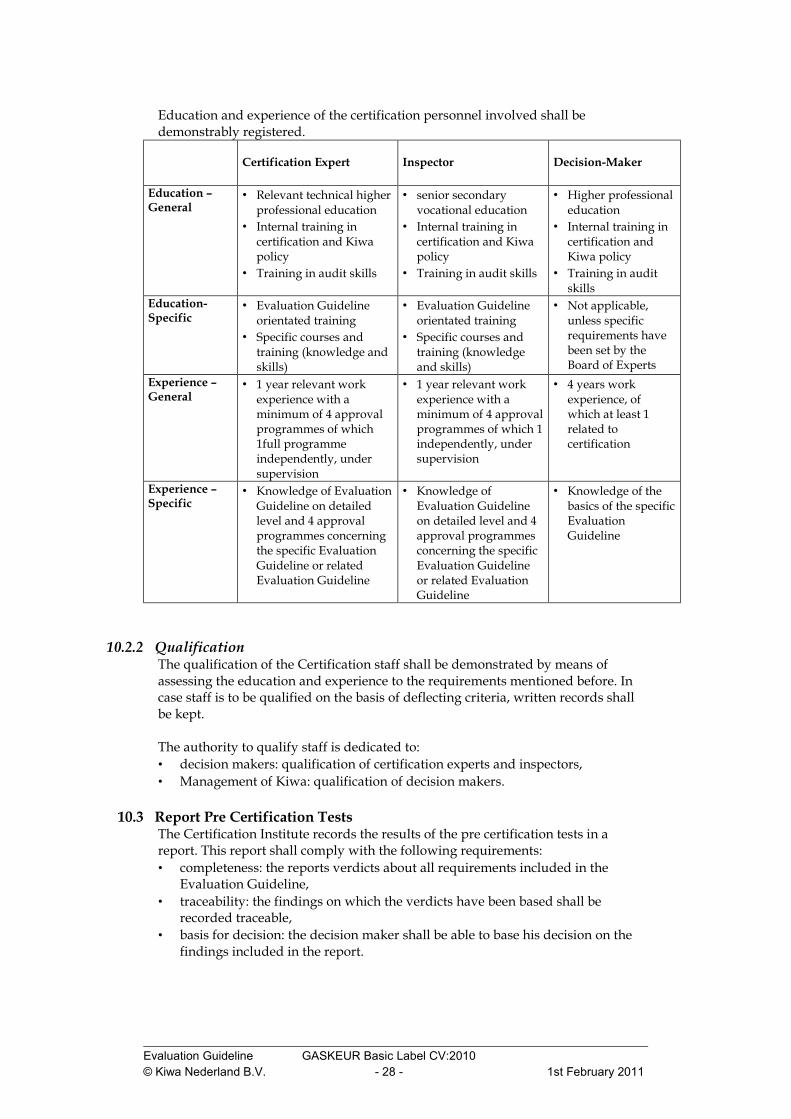
Education and experience of the certification personnel involved shall be demonstrably registered.
Certification Expert
Inspector
Decision-Maker
Education – General
• Relevant technical higher professional education
• Internal training in certification and Kiwa policy
• Training in audit skills
• senior secondary vocational education
• Internal training in certification and Kiwa policy
• Training in audit skills
• Higher professional education
• Internal training in certification and Kiwa policy
• Training in audit skills
Education-Specific
• Evaluation Guideline orientated training
• Specific courses and training (knowledge and skills)
• Evaluation Guideline orientated training
• Specific courses and training (knowledge and skills)
• Not applicable, unless specific requirements have been set by the Board of Experts
Experience – General
• 1 year relevant work experience with a minimum of 4 approval programmes of which 1full programme independently, under supervision
• 1 year relevant work experience with a minimum of 4 approval programmes of which 1 independently, under supervision
• 4 years work experience, of which at least 1 related to certification
Experience – Specific
• Knowledge of Evaluation Guideline on detailed level and 4 approval programmes concerning the specific Evaluation Guideline or related Evaluation Guideline
• Knowledge of Evaluation Guideline on detailed level and 4 approval programmes concerning the specific Evaluation Guideline or related Evaluation Guideline
• Knowledge of the basics of the specific Evaluation Guideline
10.2.2 Qualification The qualification of the Certification staff shall be demonstrated by means of assessing the education and experience to the requirements mentioned before. In case staff is to be qualified on the basis of deflecting criteria, written records shall be kept. The authority to qualify staff is dedicated to: • decision makers: qualification of certification experts and inspectors, • Management of Kiwa: qualification of decision makers.
10.3 Report Pre Certification Tests The Certification Institute records the results of the pre certification tests in a report. This report shall comply with the following requirements: • completeness: the reports verdicts about all requirements included in the
Evaluation Guideline, • traceability: the findings on which the verdicts have been based shall be
recorded traceable, • basis for decision: the decision maker shall be able to base his decision on the
findings included in the report.
Evaluation Guideline GASKEUR Basic Label CV:2010 © Kiwa Nederland B.V. - 29 - 1st February 2011
10.4 Decision for Granting the Certificate The decision for granting the certificate shall be made by a qualified decision maker which has not been involved in the pre certification tests. The decision shall be recorded traceable.
10.5 Lay out of Certificate The product certificate shall be conform the model included as an annex.
10.6 Nature and Frequency of External Inspections The certification body shall carry out Audits at the supplier at regular intervals to check whether the supplier complies with his obligations. About the frequency of inspections the Board of Experts decides. At the time this Evaluation Guideline took effect, the frequency of the number of inspection visits per year is set according to Chapter 9. Inspections shall at least refer to: • The suppliers IQC-scheme and the results obtained from inspections carried out
by the supplier, • The correct way of marking of certified products • Complying with required procedures
The results of each inspection shall be traceable recorded in a report.
10.7 Corrections, Additions and Interpretations of Requirements Corrections and additions will be drawn up by the TC GASKEUR and may or may not be approved by the Board of Experts. The TC GASKEUR may record the interpretation of requirements of this Evaluation Guideline in one separate interpretation document.
Evaluation Guideline GASKEUR Basic Label CV:2010 © Kiwa Nederland B.V. - 30 - 1st February 2011
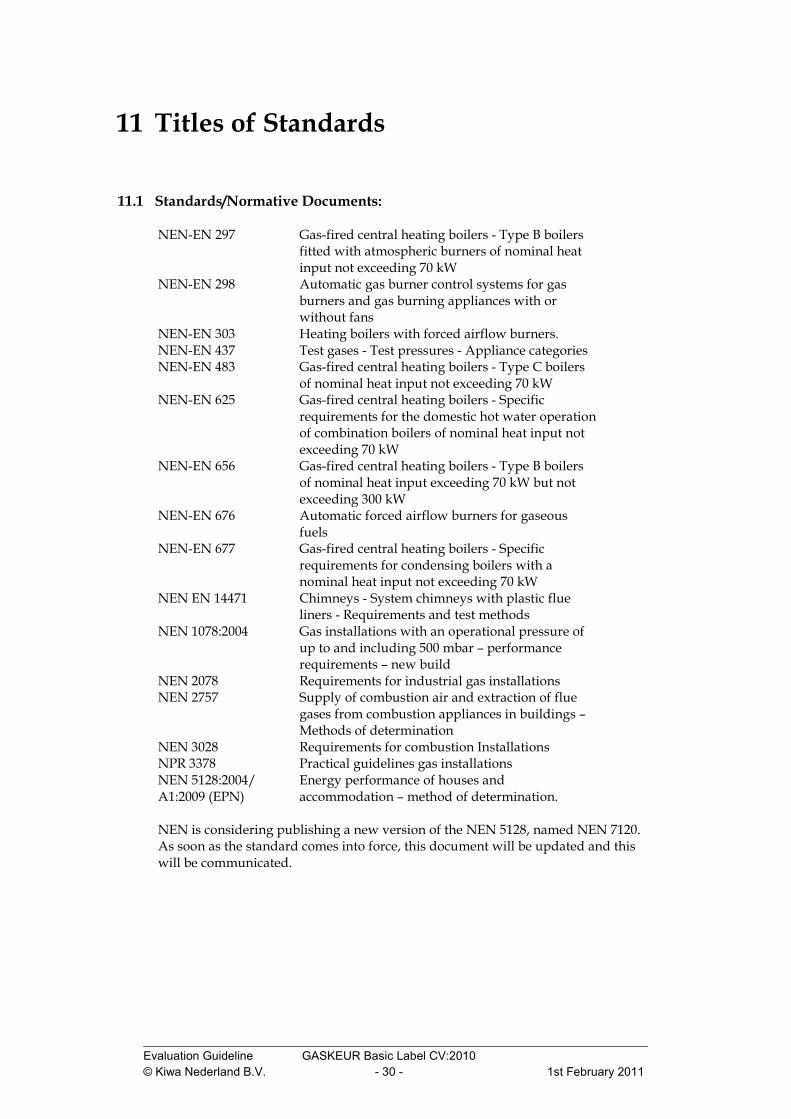
11 Titles of Standards
11.1 Standards/Normative Documents: NEN-EN 297 Gas-fired central heating boilers - Type B boilers
fitted with atmospheric burners of nominal heat input not exceeding 70 kW
NEN-EN 298 Automatic gas burner control systems for gas burners and gas burning appliances with or without fans
NEN-EN 303 Heating boilers with forced airflow burners. NEN-EN 437 Test gases - Test pressures - Appliance categories NEN-EN 483 Gas-fired central heating boilers - Type C boilers
of nominal heat input not exceeding 70 kW
NEN-EN 625 Gas-fired central heating boilers - Specific requirements for the domestic hot water operation of combination boilers of nominal heat input not exceeding 70 kW
NEN-EN 656 Gas-fired central heating boilers - Type B boilers of nominal heat input exceeding 70 kW but not exceeding 300 kW
NEN-EN 676 Automatic forced airflow burners for gaseous fuels
NEN-EN 677 Gas-fired central heating boilers - Specific requirements for condensing boilers with a nominal heat input not exceeding 70 kW
NEN EN 14471 Chimneys - System chimneys with plastic flue liners - Requirements and test methods
NEN 1078:2004 Gas installations with an operational pressure of up to and including 500 mbar – performance requirements – new build
NEN 2078 Requirements for industrial gas installations NEN 2757 Supply of combustion air and extraction of flue
gases from combustion appliances in buildings – Methods of determination
NEN 3028 Requirements for combustion Installations NPR 3378 Practical guidelines gas installations NEN 5128:2004/ A1:2009 (EPN)
Energy performance of houses and accommodation – method of determination.
NEN is considering publishing a new version of the NEN 5128, named NEN 7120. As soon as the standard comes into force, this document will be updated and this will be communicated.

Evaluation Guideline GASKEUR Basic Label CV:2010 © Kiwa Nederland B.V. - 31 - 1st February 2011
I Model Certificate
Model Certificate - GASKEUR Basic / HR / SV

Evaluation Guideline GASKEUR Basic Label CV:2010 © Kiwa Nederland B.V. - 32 - 1st February 2011
Model Certificate - GASKEUR EPN
Evaluation Guideline GASKEUR Basic Label CV:2010 © Kiwa Nederland B.V. - 33 - 1st February 2011
II Model IQC-scheme or Framework IQC Scheme
On the following page a template of an IQC scheme is given which is referred to in Chapter 8.

Evaluation Guideline GASKEUR Basic Label CV:2010 © Kiwa Nederland B.V. - 34 - 1st February 2011
Inspection Items Inspections Aspects Inspection Method
Inspection Frequency
Inspection Registration
Supplied Materials: Components:
• Material Certificates • Declarations of
conformity and/or CE certificates
• Entry Inspection of applied components
• Brand and Type • Specifications
Production Process Production apparatus, equipment: Procedures, Work instructions, used apparatus
• Registration of
procedures and equipment used.
• Inspection methods • Inspection
frequency • Registration and
documentation of inspection results and equipment used.
End Products Procedures, Work instructions, used apparatus
• Inspection methods • Inspection
frequency • Registration and
documentation of inspection results and equipment used.
• Branding • Non-compliance
boundaries
Means for measuring and testing
• List and status of used measuring and testing equipment and testing
• Calibration and maintenance reports
Logistics
• Internal transport • Storage • Packaging • Branding • Delivery
Documents • Drawings • Instructions • Labelling
Procedure in the case of non-compliance
• Procedure and documentation
Complaints procedure • Procedure, registration and closure
Evaluation Guideline GASKEUR Basic Label CV:2010 © Kiwa Nederland B.V. - 35 - 1st February 2011
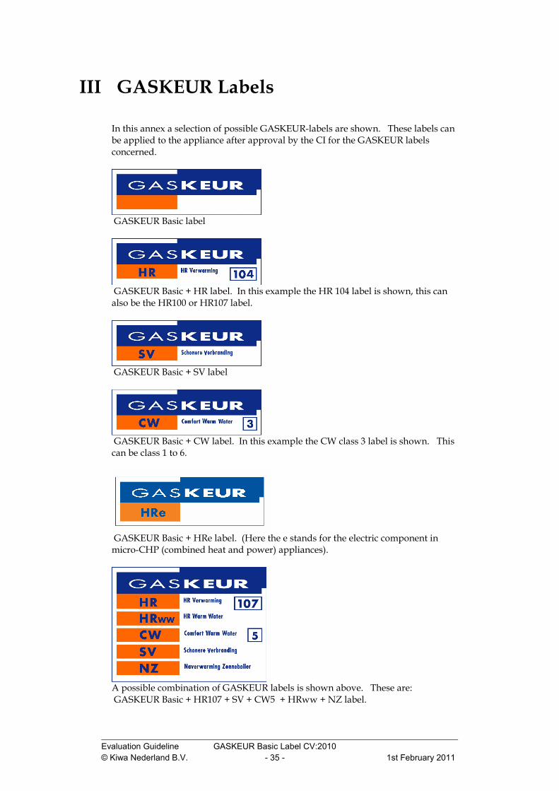
III GASKEUR Labels
In this annex a selection of possible GASKEUR-labels are shown. These labels can be applied to the appliance after approval by the CI for the GASKEUR labels concerned.
GASKEUR Basic label
GASKEUR Basic + HR label. In this example the HR 104 label is shown, this can also be the HR100 or HR107 label.
GASKEUR Basic + SV label
GASKEUR Basic + CW label. In this example the CW class 3 label is shown. This can be class 1 to 6.
GASKEUR Basic + HRe label. (Here the e stands for the electric component in micro-CHP (combined heat and power) appliances).
A possible combination of GASKEUR labels is shown above. These are: GASKEUR Basic + HR107 + SV + CW5 + HRww + NZ label.

Evaluation Guideline GASKEUR Basic Label CV:2010 © Kiwa Nederland B.V. - 36 - 1st February 2011
IV Conversion of the Efficiency from Net Value to Gross Value
The efficiency values according to the criteria relate to the net calorific value (HI) of the energy supplied. For situations where the gross calorific value (HS) is still used for communications, as is the case in NEN 5128 (EPN), the values should be converted. To do this the conversion factors (relationship between gross and net calorific value) for each form of energy supplied are used in accordance with the most recent version of NEN 5128. In the NEN 5128 the following values are given (Table C.6):
• natural gas (G25): Hi / Hs = 0.902 • propane (G31): Hi / Hs = 0.921 • butane (G30): Hi / Hs = 0.924 • electricity: Hi / Hs = 0.923
In order to convert the efficiency to the gross value the value of η determined in this Evaluation Guideline is multiplied by the ratio between the net calorific value and the gross value of the energy form(s) in question. The result is therefore smaller (efficiency seems to be lower). For an accurate conversion this should be done in relation to the supplied form of energy (pay attention to the proportion of electricity). N.B.: The η determined in this way corresponds to the η which is used in NEN 5128 (EPN) for entering appliance efficiency. Power Station Efficiency For the efficiency of the electricity generation in the power station use should be made of the value in the most recent NEN 5128, taking into account the determination of the gross and net values. In the NEN 512 the following values are given for this (art. 15.2):
• ηel = 0.39 (at gross value) • ηel;ow = 0.39 / 0.923 = 0.4225 (at net value)

Evaluation Guideline GASKEUR Basic Label CV:2010 © Kiwa Nederland B.V. - 37 - 1st February 2011
V Requirements for the Acceptance of Test Reports, Where Testing was Carried Out at the Laboratory of the Supplier
Approval Programme Possibilities for Acceptance Regarding the Approval Programme, there are two possibilities for acceptance of test reports, where testing was carried out at the laboratory of the supplier. 1. Laboratory Agreement with the Supplier;
If the supplier can produce a so-called Laboratory Agreement which has been undersigned by a CI, then the CI can accept the test results of the supplier according to the procedure documented in this Laboratory Agreement.
2. Witnessing at the Supplier’s Premises; Measurement results of the supplier can be accepted by witnessing the measurements carried out by the supplier.
The following aspects need to be taken into consideration regarding the selection of the (size of) the spot check of the measurements carried out by the supplier:
• Are there any measurement results which are close to the limit for non-compliance? Measurements in the area of the non-compliance limits must always be checked. As a rule of thumb, all these results must be within 5% of the non-compliance limit (this does not apply to all properties; common sense should also be used).
• Are there any measurement results which can be used for commercial ends (such as a HR label)? Commercially relevant measurement results shall always be checked.
• Are there any properties known regarding the test object concerned which are more critical than average (e.g. cold start using limit gas)? Properties which are known to be more critical than average shall always be checked.
• Are there significant differences between the results of the manufacturer and its own measurement results? When there are more significant differences then further measurements need to be checked. In general, around 10% of the measurements must be examined. If there are significant differences, this percentage needs to be doubled (in extreme cases, until 100% have been examined).
Furthermore, there are a number of fixed rules which apply to witness measurements in all cases, namely:
• The location where the measurements are carried out shall be clearly indicated in the report.

Evaluation Guideline GASKEUR Basic Label CV:2010 © Kiwa Nederland B.V. - 38 - 1st February 2011
• Calibration certificated from acceptable traceable calibrations (carried out by accredited calibration institutes) must be incorporated into the report, or must be traceable by the CI.
• Regarding the use inaccuracy, the measuring equipment used must comply with the same requirements which are applied to the measuring equipment of Kiwa.
• The make, model and serial number of every instrument used must be incorporated into the report.
• Verified measurement values shall be initialled on the measurement sheets by the acting certification expert.
In both cases at least once a year a comparison will be made between the measurements taken by Kiwa of an appliance which has already been tested by the supplier, and the results from the supplier’s test of the same appliance. The results of Kiwa have precedence. Correction Procedure The maximum allowable deviation between the measurement results of the supplier and Kiwa are given in Table 1 below:
Measured Value/ Parameter abs / rel value Tolerance HR Efficiency (CV nominal) absolute value ≥ -1% ;≤ +1% Compared to Kiwa HR Efficiency (CV 30%) absolute value ≥ -1,5%; ≤ +1,5% Compared to Kiwa Efficiency (Tap water) absolute value ≥ -2.5%; ≤ +2.5% Compared to Kiwa Flow relative value ≥ -10%; ≤ +10% Compared to Kiwa Heat Input relative value ≥ -2%; ≤ +2% Compared to Kiwa Temperature absolute value ≥ -1°C; ≤ +1°C Compared to Kiwa Waiting Time absolute value ≥ -2 s; ≤ +2 s Compared to Kiwa Emission CO2 absolute value ≥ -0.3 %; ≤ +0.3% Compared to Kiwa Emission CO / Nox absolute value ≥ -10 ppm; ≤ +10ppm Compared to Kiwa Pressure Resistance tap water circuit absolute value ≥ - 0.05 bar; ≤ +0.05 bar Compared to Kiwa
Table 1
The correction procedure, which is applied from the moment of comparison up to the moment of the first following comparison, has two distinct possibilities:
1. The efficiency measurement installation of the supplier is identical to the efficiency measurement installation of Kiwa (same software and components).
If the measurement values of the supplier are at or within the tolerance limits as indicated in Table 1, then no correction is needed. If the measurement values of the supplier are outside the tolerance limits as indicated in Table 1, then a correction takes place of the measurement value of the supplier based on the deviation compared to the applicable tolerance.
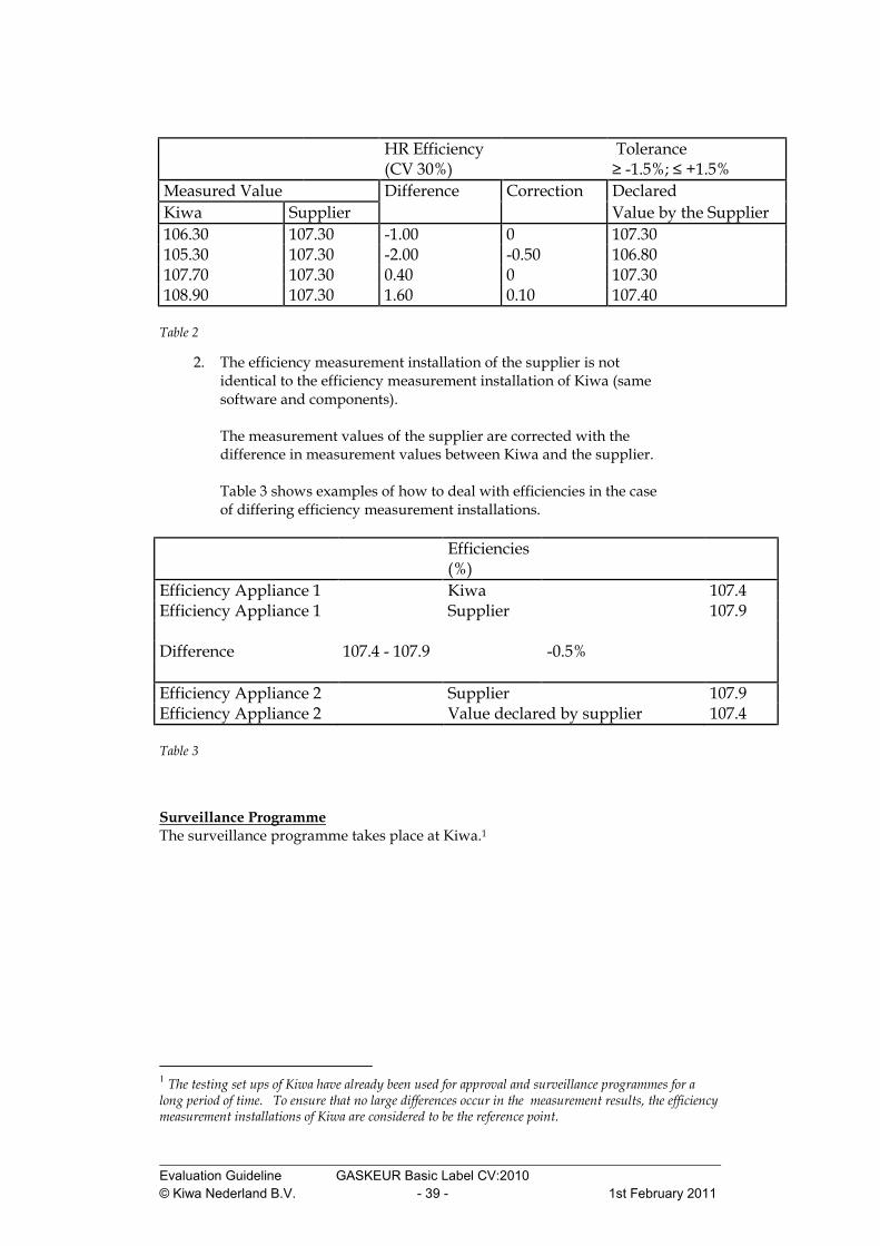
Table 2 shows examples of how corrections of efficiencies should be dealt with in the case of identical efficiency measurement installations.
Evaluation Guideline GASKEUR Basic Label CV:2010 © Kiwa Nederland B.V. - 39 - 1st February 2011
HR Efficiency (CV 30%)
Tolerance ≥ -1.5%; ≤ +1.5%
Measured Value Difference Correction Declared Kiwa Supplier Value by the Supplier 106.30 107.30 -1.00 0 107.30 105.30 107.30 -2.00 -0.50 106.80 107.70 107.30 0.40 0 107.30 108.90 107.30 1.60 0.10 107.40
Table 2
2. The efficiency measurement installation of the supplier is not identical to the efficiency measurement installation of Kiwa (same software and components).
The measurement values of the supplier are corrected with the difference in measurement values between Kiwa and the supplier. Table 3 shows examples of how to deal with efficiencies in the case of differing efficiency measurement installations.
Efficiencies (%)
Efficiency Appliance 1 Kiwa 107.4 Efficiency Appliance 1 Supplier 107.9 Difference 107.4 - 107.9 -0.5% Efficiency Appliance 2 Supplier 107.9 Efficiency Appliance 2 Value declared by supplier 107.4
Table 3
Surveillance Programme The surveillance programme takes place at Kiwa.1
1 The testing set ups of Kiwa have already been used for approval and surveillance programmes for a long period of time. To ensure that no large differences occur in the measurement results, the efficiency measurement installations of Kiwa are considered to be the reference point.

Evaluation Guideline GASKEUR Basic Label CV:2010 © Kiwa Nederland B.V. - 40 - 1st February 2011
VI Flue Gas Construction at Initial Type Testing and Product Inspection
Introduction
An analysis has been carried out by Kiwa into how deviations of efficiency values could have arisen between the initial type testing and the product inspection. The following conclusion has been made:
• Initial type testing has been carried out using a parallel flue gas system, whilst the product inspection was carried out using a concentric flue gas system, or vice versa. This can lead to deviations.
In the past the actual manner of assessing was insufficiently recorded. Currently, all variables which can have an influence on the assessment results and which are apparent to Kiwa are recorded on measurement sheets. This enables Kiwa to perform the initial type testing and the product inspection under identical conditions. However, it has not been determined which concentric flue gas pipe needs to be used for the initial type testing as well as the product inspection. This is explained in this annex. Basic Assumptions: The appliance cannot be supplied under appliance category C6
• The choice of the supplier is between an assessment using a parallel or a concentric configuration (it must of course be possible for the appliance to be brought to market in the configuration chosen). Thereafter, all later assessments must be carried out using the configuration originally selected, for both the initial type testing as well as product inspections.
• For the initial type testing and the product inspection, the supplier delivers the flue gas configuration according to the choice made, whereby the assessment is made using the shortest possible configuration, at least consisting of a terminal (wall or roof) and the components necessary to connect the appliance.
• The flue gas system chosen and used during the initial type testing will be recorded in the report (photograph, drawings etc.).
The appliance can be supplied under appliance category 6
• The choice of the supplier is between measurement using a parallel or a concentric configuration. Thereafter, all later measurements must be carried out using the configuration originally selected, for both the initial type testing as well as product inspections.
• The selected configuration for the flue gas system as described below and used during the initial type testing, will be recorded in the report (photograph, drawings etc.).
This means that the assessments are carried out using standard components as described below, for a parallel or concentric flue gas system, based on the selection of the supplier.

Evaluation Guideline GASKEUR Basic Label CV:2010 © Kiwa Nederland B.V. - 41 - 1st February 2011
• For a parallel flue gas system the following configuration shall be used: Vertical flue pipe with a length of 50 cm and a diameter of 80mm; Air inlet with a 90° bend with a diameter of 80mm;
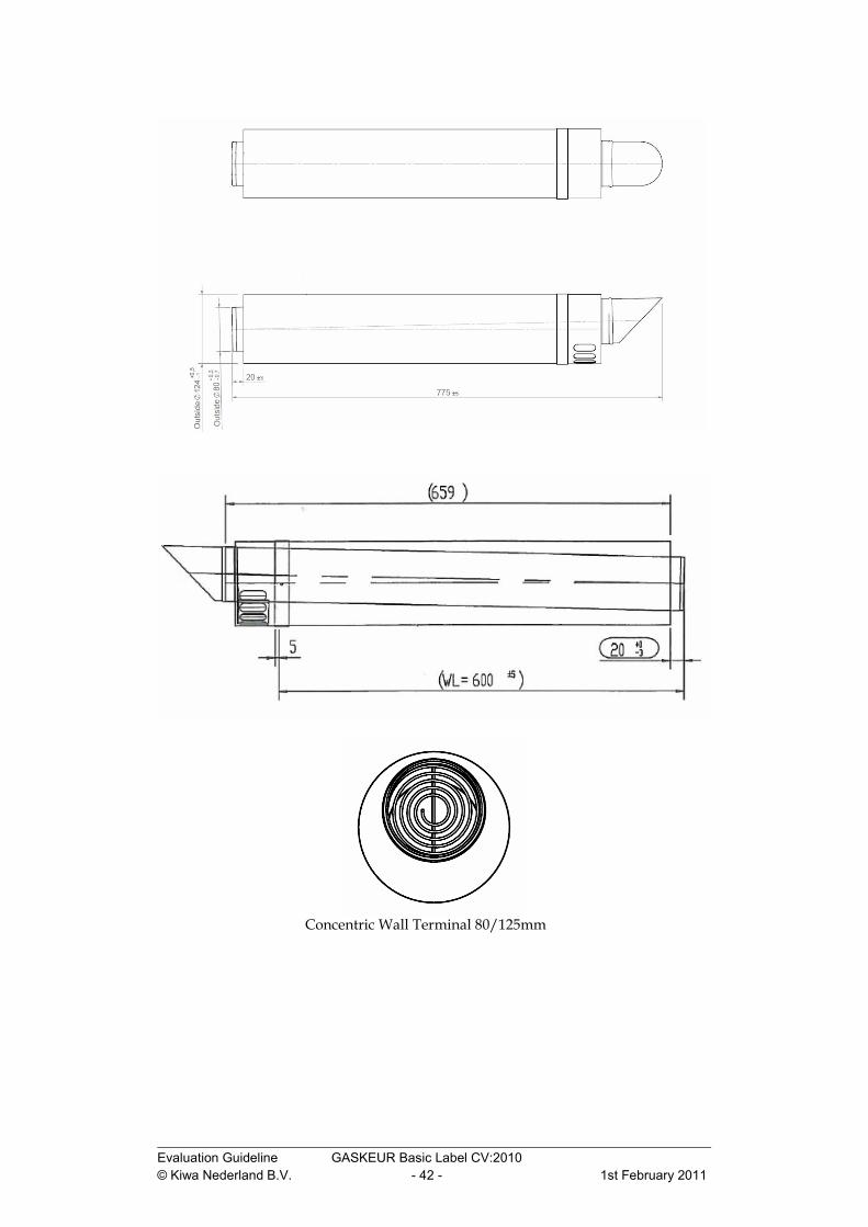
The flue pipe material is aluminium. • For a concentric flue gas system, the following configuration shall be used:
Concentric 90° bend, 80/125mm; Horizontal concentric terminal 80/125mm, complete with an
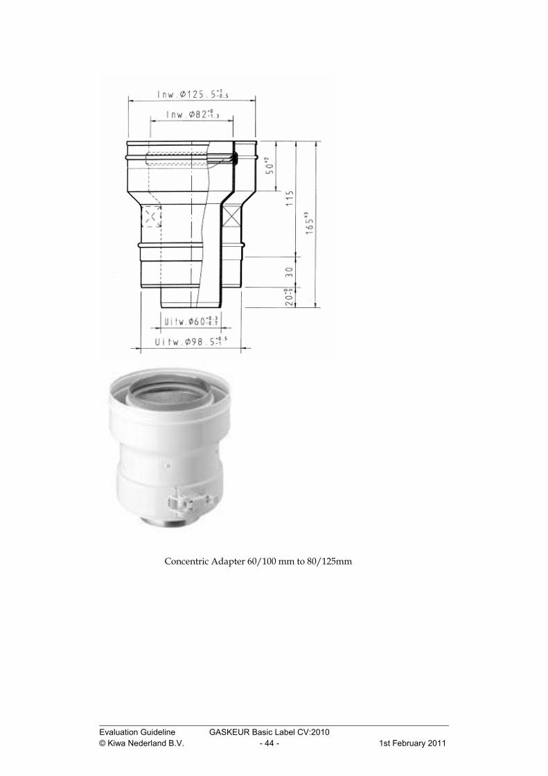
aluminium lining pipe and with a length 775mm; If the appliance is supplied with a concentric flue gas system with
different values than 80/125mm, then an adaptor (reducer) to 80/125mm needs to be utilised.
Standard Configuration of the Flue gas System for Appliances with a Heat Input up to 70 kW:
Evaluation Guideline GASKEUR Basic Label CV:2010 © Kiwa Nederland B.V. - 42 - 1st February 2011
Concentric Wall Terminal 80/125mm

Evaluation Guideline GASKEUR Basic Label CV:2010 © Kiwa Nederland B.V. - 43 - 1st February 2011
Concentric 90º bend 80/125mm
Evaluation Guideline GASKEUR Basic Label CV:2010 © Kiwa Nederland B.V. - 44 - 1st February 2011
Concentric Adapter 60/100 mm to 80/125mm
Evaluation Guideline GASKEUR Basic Label CV:2010 © Kiwa Nederland B.V. - 45 - 1st February 2011
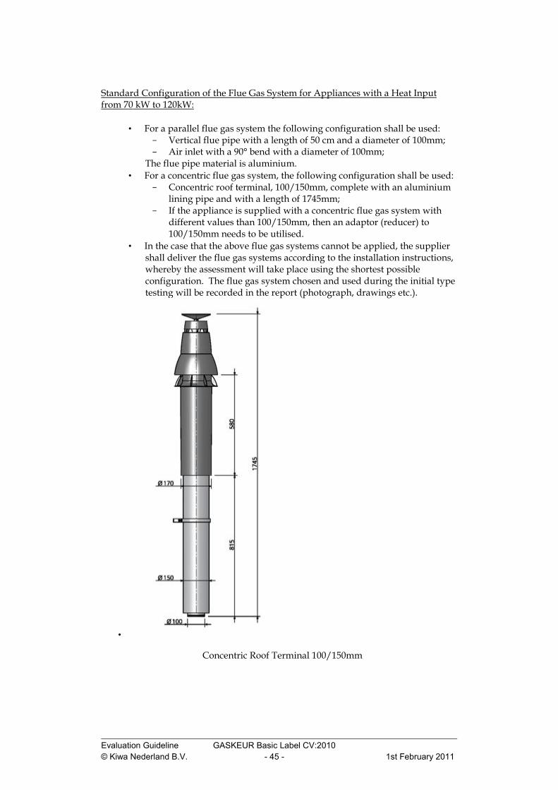
Standard Configuration of the Flue Gas System for Appliances with a Heat Input from 70 kW to 120kW:
• For a parallel flue gas system the following configuration shall be used: Vertical flue pipe with a length of 50 cm and a diameter of 100mm; Air inlet with a 90° bend with a diameter of 100mm;
The flue pipe material is aluminium. • For a concentric flue gas system, the following configuration shall be used:
Concentric roof terminal, 100/150mm, complete with an aluminium lining pipe and with a length of 1745mm;
If the appliance is supplied with a concentric flue gas system with different values than 100/150mm, then an adaptor (reducer) to 100/150mm needs to be utilised.
• In the case that the above flue gas systems cannot be applied, the supplier shall deliver the flue gas systems according to the installation instructions, whereby the assessment will take place using the shortest possible configuration. The flue gas system chosen and used during the initial type testing will be recorded in the report (photograph, drawings etc.).
•
Concentric Roof Terminal 100/150mm

Evaluation Guideline GASKEUR Basic Label CV:2010 © Kiwa Nederland B.V. - 46 - 1st February 2011
Appliances with a Heat Input Exceeding 120 kW: • The choice of the supplier is between an assessment using a parallel or a
concentric configuration (it must of course be possible for the appliance to be brought to market in the configuration chosen). Thereafter, all later assessments must be carried out using the configuration originally selected, for both the initial type testing as well as product inspections.
• For the initial type testing and the product inspection, the supplier delivers the flue gas configuration according to the choice made, whereby the assessment is made using the shortest possible configuration, at least consisting of a terminal (wall or roof) and the components necessary to connect the appliance.
• The flue gas system chosen and used during the initial type testing will be recorded in the report (photograph, drawings etc.).
Installation of Flue gas System: • Concentric:
The outlet of the concentric wall terminal needs to be placed facing the same direction as the airflow in the testing area, in order to avoid the build up of resistance in the flue gas system and the associated influence on the heat input.
• Parallel: The 90º bend for the air inlet shall be placed facing the same direction as the airflow in the testing area.