Bridgelux Vero 18 Array Series - Farnell element14 · Introduction. Vero represents a revolutionary...
20
Bridgelux ® Vero ® 18 Array Series Product Data Sheet DS32 BXRC-27x4000 | 30x4000 | 35x4000 | 40x4000 | 50x4000
Transcript of Bridgelux Vero 18 Array Series - Farnell element14 · Introduction. Vero represents a revolutionary...

Bridgelux® Vero® 18 Array SeriesProduct Data Sheet DS32
BXRC-27x4000 | 30x4000 | 35x4000 | 40x4000 | 50x4000

Introduction
Vero represents a revolutionary advancement in chip on board (COB) light source technology and innovation. Vero
LED light sources simplify luminaire design and manufacturing processes, improve light quality, and define a platform
for future functionality integration.
Vero is available in four different light emitting surface (LES) configurations and has been engineered to reliably
operate over a broad current range, enabling new degrees of flexibility in luminaire design optimization. Vero arrays
deliver increased lumen density to enable improved beam control and precision lighting with 2 and 3 SDCM color
control standard for clean and consistent uniform lighting.
Vero includes an on board connector port to enable solder free electrical interconnect and simple easy to use
mounting features to enable plug-and-play installation.
Ve
roFeatures
• Market leading efficacy of 130 lm/W typical
• Vero 18 lumen output performance ranges from 1600 to 7600 lumens
• Broad range of CCT options from 2700K to 5000K
• CRI options include minimum 70, 80, and 90, 2 and 3 SDCM color control for 2700K-4000K CCT
• Reliable operation at up to 2X nominal drive current
• Radial die pattern and improved lumen density
• Thermally isolated solder pads
• Onboard connector port
• Top side part number markings
Benefits
• Broad application coverage for interior and exterior lighting
• Flexibility for application driven lighting design requirements
• High quality true color reproduction
• Uniform consistent white light
• Flexibility in design optimization
• Improved optical control
• Enhanced ease of use and manufacturability
• Solderless connectivity enables plug & play installation and field upgradability
• Improved inventory management and quality control

Contents
Product Feature Map 2
Product Nomenclature 2
Product Selection Guide 3
Performance at Commonly Used Drive Currents 4
Electrical Characteristics 6
Absolute Maximum Ratings 7
Performance Curves 8
Typical Radiation Pattern 11
Typical Color Spectrum 12
Mechanical Dimensions 13
Color Binning Information 14
Packaging 15
Design Resources 17
Precautions 17
Disclaimers 17
About Bridgelux 18
1

Product Feature Map
Vero 18 is the second largest form factor in the Vero family of next generation solid state light sources. In addition to delivering the performance and light quality required for many lighting applications, Vero incorporates
Product Nomenclature
The part number designation for Bridgelux Vero LED arrays is explained as follows:
several features to simplify the design integration and manufacturing process, accelerate time to market and reduce system costs. Please consult the Bridgelux Vero Array Series Product Brief for more information on the Vero family of products.
2D Bar code provides full manufacturing traceability
Polarity indication marks simplify manufacturing operator instructions
Optics location/mounting features
Mounting holes
Zhaga Book 3 compatible mounting locations
Solderless connector port enables simplified manufacturing processes, reduced inventory
carrying costs and can enable field upgradability
Thermally isolated solder pads reduce manufacturing cycle time and complexity
Tc Measurement point
Radial die configuration improves lumen density and beam control
2
1 2 3 4 5 6 7 8 9 10 11 – 12 – 13 14
Product Family CCT Bin Options
22 = 2 SDCM23 = 3 SDCM24 = 4 SDCM
Nominal Flux
4000 = 4000lm
Minimum CRIC = 70 CRIE = 80 CRIG = 90 CRI
Array Configuration
Nominal CCT27 = 2,700K30 = 3,000K35 = 3,500K40 = 4,000K50 = 5,000K
BXRC – 30 E 4000 – F – 23
Optional Molex Pico-EZmate™ connector harness (sold separately)

Product Selection Guide
The following product configurations are available:
Table 1: Selection Guide, Pulsed Measurement Data (Tj = Tc = 25°C)
Notes for Tables 1 & 2:
1. Nominal CCT as defined by ANSI C78.377-2011.
2. CRI Values are minimums. Minimum R9 value for 80 CRI products is 0, the minimum R9 values for 90 CRI products is 50.
3. Drive current is referred to as nominal drive current.
4. Products tested under pulsed condition (10ms pulse width) at rated test current where Tj (junction temperature) = Tc (case temperature) = 25°C.
5. Typical performance values are provided as a reference only and are not a guarantee of performance.
6. Bridgelux maintains a ± 7% tolerance on flux measurements.
7. Minimum flux values at the rated test current are guaranteed by 100% test.
8. Typical stabilized DC performance values are provided as reference only and are not a guarantee of performance.
9. Typical performance is estimated based on operation under DC (direct current) with LED array mounted onto a heat sink with thermal interface material and the case temperature maintained at 85°C. Based on Bridgelux test setup, values may vary depending on the thermal design of the luminaire and/or the exposed environment to which the product is subjected.
10. Minimum flux values at elevated temperatures are provided for reference only and are not guaranteed by 100% production testing. Based on Bridgelux test setup, values may vary depending on the thermal design of the luminaire and/or the exposed environment to which the product is subjected
Part NumberNominal CCT1
(K)CRI2
Nominal Drive Current3
(mA)
Typical Pulsed Flux4,5,6
Tc = 25ºC(lm)
Minimum Pulsed Flux6,7
Tc = 25ºC(lm)
Typical Vf (V)
Typical Power
(W)
Typical Efficacy (lm/W)
BXRC-27E4000-F-2x 2700 80 1050 3850 3605 29.5 31.0 124
BXRC-27G4000-F-2x 2700 90 1050 3100 2832 29.5 31.0 100
BXRC-30E4000-F-2x 3000 80 1050 4050 3691 29.5 31.0 131
BXRC-30G4000-F-2x 3000 90 1050 3230 2929 29.5 31.0 104
BXRC-35E4000-F-2x 3500 80 1050 4150 3760 29.5 31.0 134
BXRC-40E4000-F-2x 4000 80 1050 4200 3884 29.5 31.0 135
BXRC-40G4000-F-2x 4000 90 1050 3670 3300 29.5 31.0 118
BXRC-50C4000-F-24 5000 70 1050 4430 4000 29.5 31.0 143
BXRC-50E4000-F-24 5000 80 1050 4200 3783 29.5 31.0 136
BXRC-50G4000-F-24 5000 90 1050 3885 3560 29.5 31.0 125
Part NumberNominal CCT1
(K)CRI2
Nominal Drive Current3
(mA)
Typical DC FluxTc = 85ºC
(lm)
Minimum DC Flux10
Tc = 85ºC(lm)
Typical Vf (V)
Typical Power
(W)
Typical Efficacy (lm/W)
BXRC-27E4000-F-2x 2700 80 1050 3492 3269 28.6 30.0 116
BXRC-27G4000-F-2x 2700 90 1050 2728 2492 28.6 30.0 91
BXRC-30E4000-F-2x 3000 80 1050 3662 3337 28.6 30.0 122
BXRC-30G4000-F-2x 3000 90 1050 2842 2578 28.6 30.0 95
BXRC-35E4000-F-2x 3500 80 1050 3770 3416 28.6 30.0 125
BXRC-40E4000-F-2x 4000 80 1050 3793 3508 28.6 30.0 126
BXRC-40G4000-F-2x 4000 90 1050 3230 2904 28.6 30.0 108
BXRC-50C4000-F-24 5000 70 1050 3898 3520 28.6 30.0 130
BXRC-50E4000-F-24 5000 80 1050 3696 3329 28.6 30.0 123
BXRC-50G4000-F-24 5000 90 1050 3419 3133 28.6 30.0 114
Table 2: Selection Guide, Stabilized DC Performance (Tc = 85°C) 8,9
3

Performance at Commonly Used Drive Currents
Vero LED arrays are tested to the specifications shown using the nominal drive currents in Table 1. Vero may also
be driven at other drive currents dependent on specific application design requirements. The performance at any
drive current can be derived from the current vs. voltage characteristics shown in Figure 1 and the flux vs. current
characteristics shown in Figure 2. The performance at commonly used drive currents is summarized in Table 3.
4
Table 3: Performance at Commonly Used Drive Currents
Part Number CRIDrive
Current1
(mA)
Typical Vf Tc = 25ºC
(V)
Typical Power
Tc = 25ºC(W)
Typical Flux2
Tc = 25ºC(lm)
Typical DC Flux3 Tc = 85ºC
(lm)
Typical Efficacy Tc = 25ºC(lm/W)
BXRC-27E4000-F-2x 80
500 28.1 14.1 1985 1794 141
700 28.7 20.1 2701 2443 134
1050 29.5 31.0 3850 3492 124
1400 30.2 42.3 4891 4447 116
2100 31.6 66.4 6587 6037 99
BXRC-27G4000-F-2x 90
500 28.1 14.1 1598 1402 114
700 28.7 20.1 2175 1909 108
1050 29.5 31.0 3100 2728 100
1400 30.2 42.3 3938 3475 93
2100 31.6 66.4 5304 4717 80
BXRC-30E4000-F-2x 80
500 28.1 14.1 2088 1882 149
700 28.7 20.1 2841 2562 141
1050 29.5 31.0 4050 3662 131
1400 30.2 42.3 5145 4664 122
2100 31.6 66.4 6929 6331 104
BXRC-30G4000-F-2x 90
500 28.1 14.1 1665 1460 119
700 28.7 20.1 2266 1989 113
1050 29.5 31.0 3230 2842 104
1400 30.2 42.3 4103 3620 97
2100 31.6 66.4 5526 4914 83
BXRC-35E4000-F-2x 80
500 28.1 14.1 2139 1937 152
700 28.7 20.1 2912 2638 145
1050 29.5 31.0 4150 3770 134
1400 30.2 42.3 5272 4802 125
2100 31.6 66.4 7100 6518 107
Notes for Table 3:
1. Alternate drive currents in Table 3 are provided for reference only and are not a guarantee of performance.
2. Bridgelux maintains a ± 7% tolerance on flux measurements.
3. Typical stabilized DC performance values are provided as reference only and are not a guarantee of performance.

5
Performance at Commonly Used Drive Currents
Notes for Table 3:
1. Alternate drive currents in Table 3 are provided for reference only and are not a guarantee of performance.
2. Bridgelux maintains a ± 7% tolerance on flux measurements.
3. Typical stabilized DC performance values are provided as reference only and are not a guarantee of performance.
Table 3: Performance at Commonly Used Drive Currents (Continued)
Part Number CRIDrive
Current1
(mA)
Typical Vf Tc = 25ºC
(V)
Typical Power
Tc = 25ºC(W)
Typical Flux2
Tc = 25ºC(lm)
Typical DC Flux3 Tc = 85ºC
(lm)
Typical Efficacy Tc = 25ºC(lm/W)
BXRC-40E4000-F-2x 80
500 28.1 14.1 2165 1949 153
700 28.7 20.1 2947 2654 146
1050 29.5 31.0 4200 3793 135
1400 30.2 42.3 5336 4831 125
2100 31.6 66.4 7186 6558 107
BXRC-40G4000-F-2x 90
500 28.1 14.1 1892 1659 135
700 28.7 20.1 2575 2260 128
1050 29.5 31.0 3670 3230 118
1400 30.2 42.3 4662 4113 110
2100 31.6 66.4 6279 5584 95
BXRC-50C4000-F-24 70
500 28.1 14.1 2283 2003 163
700 28.7 20.1 3108 2727 155
1050 29.5 31.0 4430 3898 143
1400 30.2 42.3 5628 4965 133
2100 31.6 66.4 7579 6740 114
BXRC-50E4000-F-24 80
500 28.1 14.1 2165 1899 154
700 28.7 20.1 2947 2586 147
1050 29.5 31.0 4200 3696 136
1400 30.2 42.3 5336 4707 126
2100 31.6 66.4 7186 6390 108
BXRC-50G4000-F-24 90
500 28.1 14.1 2003 1757 143
700 28.7 20.1 2726 2392 136
1050 29.5 31.0 3885 3419 125
1400 30.2 42.3 4936 4354 117
2100 31.6 66.4 6647 5911 100
Electrical Characteristics
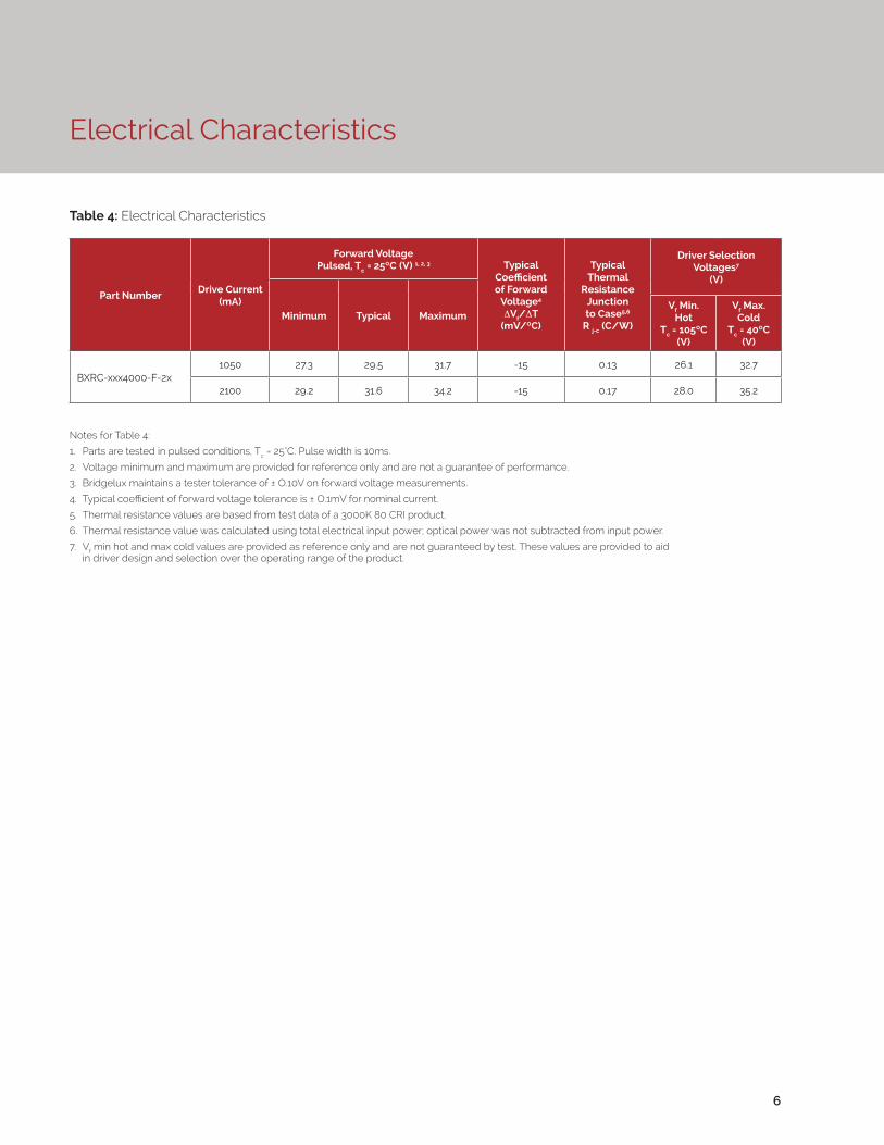
Notes for Table 4:
1. Parts are tested in pulsed conditions, Tc = 25°C. Pulse width is 10ms.
2. Voltage minimum and maximum are provided for reference only and are not a guarantee of performance.
3. Bridgelux maintains a tester tolerance of ± O.10V on forward voltage measurements.
4. Typical coefficient of forward voltage tolerance is ± O.1mV for nominal current.
5. Thermal resistance values are based from test data of a 3000K 80 CRI product.
6. Thermal resistance value was calculated using total electrical input power; optical power was not subtracted from input power.
7. Vf min hot and max cold values are provided as reference only and are not guaranteed by test. These values are provided to aid in driver design and selection over the operating range of the product.
Table 4: Electrical Characteristics
6
Part NumberDrive Current
(mA)
Forward VoltagePulsed, Tc = 25ºC (V) 1, 2, 3 Typical
Coefficient of Forward
Voltage4 ∆Vf/∆T
(mV/ºC)
Typical Thermal
Resistance Junction to Case5,6
R j-c (C/W)
Driver Selection Voltages7
(V)
Minimum Typical MaximumVf Min.
Hot Tc = 105ºC
(V)
Vf Max. Cold
Tc = 40ºC (V)
BXRC-xxx4000-F-2x1050 27.3 29.5 31.7 -15 0.13 26.1 32.7
2100 29.2 31.6 34.2 -15 0.17 28.0 35.2

7
Absolute Maximum Ratings
Notes for Table 5:
1. For IEC 62717 requirement, please consult your Bridgelux sales representative.
2. Refer to Bridgelux Application Note AN31: Assembly Considerations for Bridgelux Vero LED Arrays.
3. DC Forward Current for LM-80 is the maximum drive current for which LM-80 data is currently available.
4. Lumen maintenance (L70) and lifetime predictions are valid for drive current and case temperature conditions used for LM-80 testing as included in the applicable LM-80 test report for these arrays. Contact your Bridgelux sales representatives for LM-80 report.
5. Arrays may be driven at higher currents however lumen maintenance may be reduced.
6. Bridgelux recommends a maximum duty cycle of 10% and pulse width of 20 ms when operating LED Arrays at maximum peak pulsed current specified. Maximum peak pulsed currents indicate values where LED Arrays can be driven without catastrophic failures.
7. Light emitting diodes are not designed to be driven in reverse voltage and will not produce light under this condition. Maximum rating provided for reference only.
Parameter Maximum Rating
LED Junction Temperature (Tj) 150°C
Storage Temperature -40°C to +105°C
Operating Case Temperature1 (Tc) 105°C
Soldering Temperature2 350°C or lower for a maximum of 10 seconds
Maximum Drive Current3,4,5 2100mA
Maximum Peak Pulsed Drive Current6 3000mA
Maximum Reverse Voltage7 -55V
Table 5: Maximum Ratings

Performance Curves
8
Note for Figure 2:
1. Bridgelux does not recommend driving high power LEDs at low currents. Doing so may produce unpredictable results. Pulse width modulation (PWM) is recommended for dimming effects.
Figure 1: Drive Current vs. Voltage (Tj = Tc = 25°C)
Figure 2: Typical Relative Luminous Flux vs. Drive Current (Tj = Tc = 25°C)

9
Performance Curves
Figure 3: Typical DC Flux vs. Case Temperature
Figure 4: Typical DC ccy Shift vs. Case Temperature
Notes for Figures 3-4:
1. Characteristics shown for warm white based on 3000K and 80 CRI.
2. Characteristics shown for neutral white based on 4000K and 80 CRI.
3. Characteristics shown for cool white based on 5000K and 70 CRI.
4. For other color SKUs, the shift in color will vary. Please contact your Bridgelux Sales Representative for more information.

Performance Curves
10
Notes for Figure 5:
1. Characteristics shown for warm white based on 3000K and 80 CRI.
2. Characteristics shown for neutral white based on 4000K and 80 CRI.
3. Characteristics shown for cool white based on 5000K and 70 CRI.
4. For other color SKUs, the shift in color will vary. Please contact your Bridgelux Sales Representative for more information.
Figure 5: Typical ccx Shift vs. Case Temperature

Typical Radiation Pattern
11
Figure 6: Typical Spatial Radiation Pattern
Figure 7: Typical Polar Radiation Pattern
Note for Figure 6:
1. Typical viewing angle is 120⁰.
2. The viewing angle is defined as the off axis angle from the centerline where Iv is ½ of the peak value.

12
Typical Color Spectrum
Figure 8: Typical Color Spectrum
Notes for Figure 8:
1. Color spectra measured at rated current for Tj = Tc = 25°C.
2. Color spectra shown for warm white is 3000K and 80 CRI.
3. Color spectra shown for neutral white is 4000K and 80 CRI.
4. Color spectra shown for cool white is 5000K and 70 CRI.

Mechanical Dimensions
Figure 9: Drawing for Vero 18 LED Array
13
Notes for Figure 9:
1. Drawings are not to scale.
2. Drawing dimensions are in millimeters.
3. Unless otherwise specified, tolerances are ±0.01mm.
4. Mounting holes (2X) are for M2.5 screws.
5. Bridgelux recommends two tapped holes for mounting screws with 31.4 ± 0.10mm center-to-center spacing.
6. Screws with flat shoulders (pan, dome, button, round, truss, mushroom) provide optimal torque control. Do NOT use flat, countersink, or raised head screws.
7. Solder pads and connector port are labeled “+” and “-“ to denote positive and negative, respectively.
8. It is not necessary to provide electrical connections to both the solder pads and the connector port. Either set may be used depending on application specific design requirements.
9. Refer to Application Notes AN30 and AN31 for product handling, mounting and heat sink recommendations.
10. The optical center of the LED Array is nominally defined by the mechanical center of the array to a tolerance of ± 0.2mm.
11. Bridgelux maintains a flatness of 0.10mm across the mounting surface of the array.
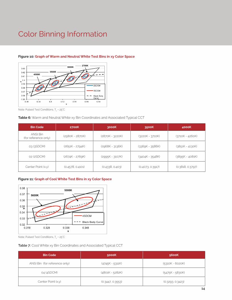
Figure 10: Graph of Warm and Neutral White Test Bins in xy Color Space
Figure 11: Graph of Cool White Test Bins in xy Color Space
Color Binning Information
14
Bin Code 2700K 3000K 3500K 4000K
ANSI Bin(for reference only)
(2580K - 2870K) (2870K - 3220K) (3220K - 3710K) (3710K - 4260K)
03 (3SDCM) (2651K - 2794K) (2968K - 3136K) (3369K - 3586K) (3851K - 4130K)
02 (2SDCM) (2674K - 2769K) (2995K - 3107K) (3404K - 3548K) (3895K - 4081K)
Center Point (x,y) (0.4578, 0.4101) (0.4338, 0.403) (0.4073, 0.3917) (0.3818, 0.3797)
Table 6: Warm and Neutral White xy Bin Coordinates and Associated Typical CCT
Bin Code 5000K 5600K
ANSI Bin (for reference only) (4745K - 5311K) (5310K - 6020K)
04 (4SDCM) (4801K - 5282K) (5475K - 5830K)
Center Point (x,y) (0.3447, 0.3553) (0.3293, 0.3423)
Table 7: Cool White xy Bin Coordinates and Associated Typical CCT
Note: Pulsed Test Conditions, Tc = 25°C
Note: Pulsed Test Conditions, Tc = 25°C
Packaging
15
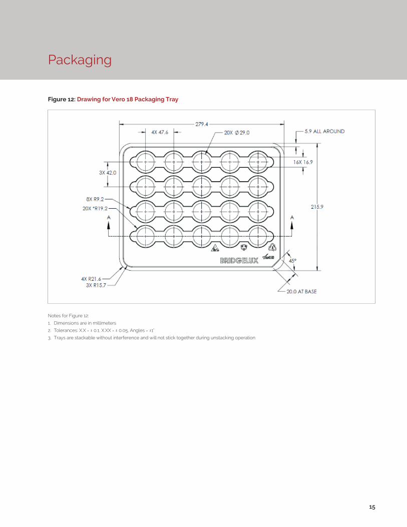
Figure 12: Drawing for Vero 18 Packaging Tray
Notes for Figure 12:
1. Dimensions are in millimeters
2. Tolerances: X.X = ± 0.1, X.XX = ± 0.05, Angles = ±1°
3. Trays are stackable without interference and will not stick together during unstacking operation
Packaging
16
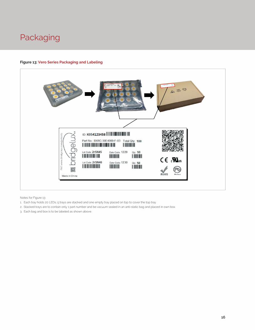
Figure 13: Vero Series Packaging and Labeling
Notes for Figure 13:
1. Each tray holds 20 LEDs, 5 trays are stacked and one empty tray placed on top to cover the top tray.
2. Stacked trays are to contain only 1 part number and be vacuum sealed in an anti-static bag and placed in own box.
3. Each bag and box is to be labeled as shown above.
Design Resources
Disclaimers
Precautions
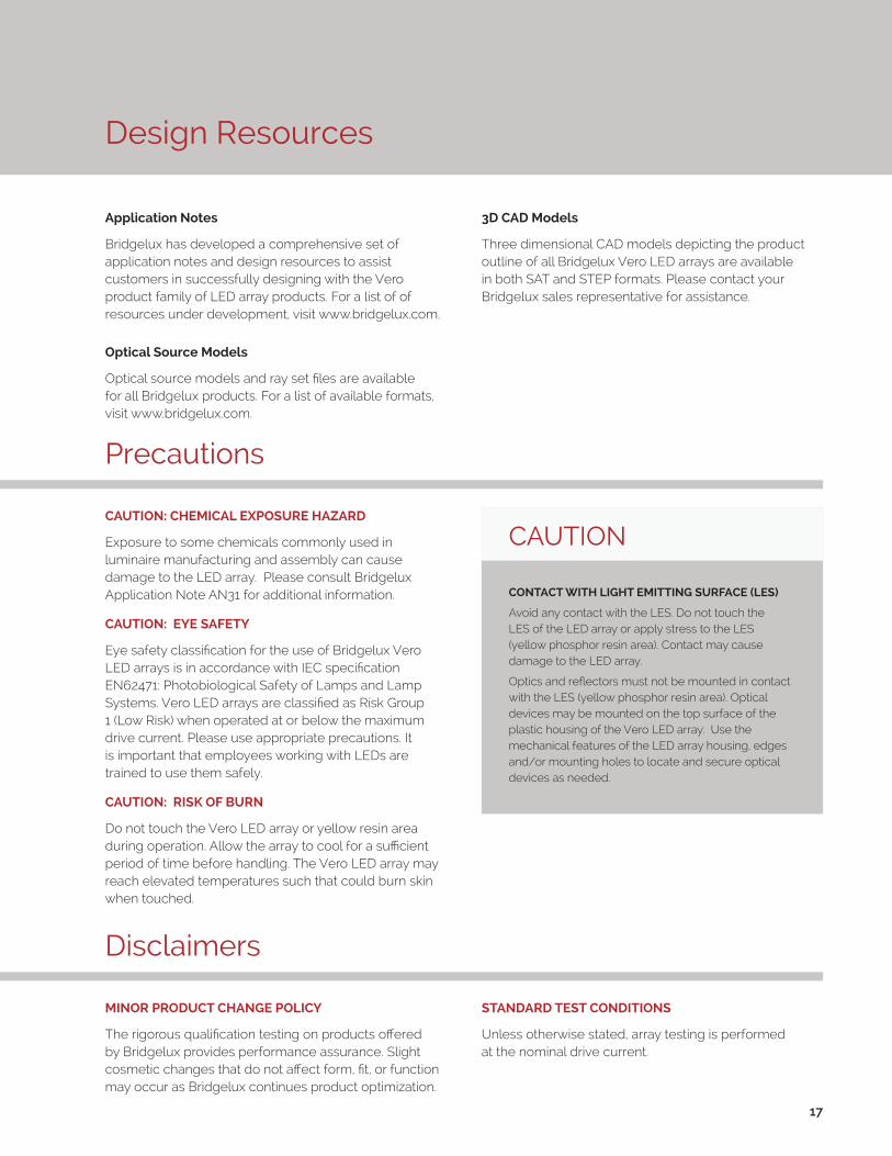
Application Notes
Bridgelux has developed a comprehensive set of application notes and design resources to assist customers in successfully designing with the Vero product family of LED array products. For a list of of resources under development, visit www.bridgelux.com.
Optical Source Models
Optical source models and ray set files are available for all Bridgelux products. For a list of available formats, visit www.bridgelux.com.
MINOR PRODUCT CHANGE POLICY
The rigorous qualification testing on products offered by Bridgelux provides performance assurance. Slight cosmetic changes that do not affect form, fit, or function may occur as Bridgelux continues product optimization.
CAUTION: CHEMICAL EXPOSURE HAZARD
Exposure to some chemicals commonly used in luminaire manufacturing and assembly can cause damage to the LED array. Please consult Bridgelux Application Note AN31 for additional information.
CAUTION: EYE SAFETY
Eye safety classification for the use of Bridgelux Vero LED arrays is in accordance with IEC specification EN62471: Photobiological Safety of Lamps and Lamp Systems. Vero LED arrays are classified as Risk Group 1 (Low Risk) when operated at or below the maximum drive current. Please use appropriate precautions. It is important that employees working with LEDs are trained to use them safely.
CAUTION: RISK OF BURN
Do not touch the Vero LED array or yellow resin area during operation. Allow the array to cool for a sufficient period of time before handling. The Vero LED array may reach elevated temperatures such that could burn skin when touched.
3D CAD Models
Three dimensional CAD models depicting the product outline of all Bridgelux Vero LED arrays are available in both SAT and STEP formats. Please contact your Bridgelux sales representative for assistance.
17
CAUTION
CONTACT WITH LIGHT EMITTING SURFACE (LES)
Avoid any contact with the LES. Do not touch the LES of the LED array or apply stress to the LES (yellow phosphor resin area). Contact may cause damage to the LED array.
Optics and reflectors must not be mounted in contact with the LES (yellow phosphor resin area). Optical devices may be mounted on the top surface of the plastic housing of the Vero LED array. Use the mechanical features of the LED array housing, edges and/or mounting holes to locate and secure optical devices as needed.
STANDARD TEST CONDITIONS
Unless otherwise stated, array testing is performed at the nominal drive current.

18
About Bridgelux
© 2015 Bridgelux, Inc. All rights reserved 2014. Product specifications are subject to change without notice. Bridgelux, the Bridgelux stylized logo design and Vero are registered trademarks, and Decor Series is a trademark of Bridgelux, Inc. All other trademarks are the property of their respective owners.
Bridgelux Vero 18 Array Series Product Data Sheet DS32 Rev. F (01/2015)
101 Portola Avenue
Livermore, CA 94551
Tel (925) 583-8400
Fax (925) 583-8410
www.bridgelux.com
Bridgelux is a leading developer and manufacturer of technologies and solutions transforming the $40 billion global lighting industry into a $100 billion market opportunity. Based in Livermore, California, Bridgelux is a pioneer in solid state lighting (SSL), expanding the market for light emitting diode (LED) technologies by driving down the cost of LED lighting systems. Bridgelux’s patented light source technology replaces traditional technologies (such as incandescent, halogen, fluorescent and high intensity discharge lighting) with integrated, solid state lighting solutions that enable lamp and luminaire manufacturers to provide high performance and energy efficient white light for the rapidly growing interior and exterior lighting markets, including street lights, commercial lighting and consumer applications.
For more information about the company, please visit bridgelux.com.