
Application Note AN30 Thermal Management for · PDF fileApplication Note AN30: Thermal...
31
Application Note AN30 Thermal Management for Bridgelux Vero Series LED Arrays June 25, 2013 101 Portola Avenue, Livermore, CA 94551 • Tel: (925) 583 - 8400 • Fax: (925) 583 - 8401 • www.bridgelux.com Introduction The Bridgelux family of Vero Array products delivers high performance, compact, and cost-effective solid- state lighting solutions to serve the general lighting market. These products combine the higher efficiency, lifetime, and reliability benefits of LEDs with the light output levels of many conventional lighting sources. Optimizing performance and reliability of a lighting system using Bridgelux Vero Series LED Arrays requires careful consideration of thermal management solutions, handling and assembly, selection of electronic drivers and selection of secondary optics. Application Notes AN30, AN31, AN32 and AN36 respectively deal with each of these topics in depth. To achieve optimal performance of the LED Arrays, proper thermal management must be selected or designed. The purpose of this application note is to assist and provide guidance to luminaire designers in the area of thermal management and component selection for use with Bridgelux Vero LED Arrays. This application note provides relevant electrical and thermal characteristics of the Vero LED Arrays, relationship between electrical power and heating power, a review of the fundamentals of heat transfer, design rules and recommendations for best thermal management of Vero LED Arrays, and discussion about the key components used for thermal management.
Transcript of Application Note AN30 Thermal Management for · PDF fileApplication Note AN30: Thermal...

Application Note AN30 Thermal Management for Bridgelux Vero Series LED Arrays June 25, 2013
101 Portola Avenue, Livermore, CA 94551 • Tel : (925) 583 -8400 • Fax: (925) 583 -8401 • www.br idgelux.com
Introduction
The Bridgelux family of Vero Array products delivers high performance, compact, and cost-effective solid-state lighting solutions to serve the general lighting market. These products combine the higher efficiency, lifetime, and reliability benefits of LEDs with the light output levels of many conventional lighting sources.
Optimizing performance and reliability of a lighting system using Bridgelux Vero Series LED Arrays requires careful consideration of thermal management solutions, handling and assembly, selection of electronic drivers and selection of secondary optics. Application Notes AN30, AN31, AN32 and AN36 respectively deal with each of these topics in depth. To achieve optimal performance of the LED Arrays, proper thermal management must be selected or designed.
The purpose of this application note is to assist and provide guidance to luminaire designers in the area of thermal management and component selection for use with Bridgelux Vero LED Arrays. This application note provides relevant electrical and thermal characteristics of the Vero LED Arrays, relationship between electrical power and heating power, a review of the fundamentals of heat transfer, design rules and recommendations for best thermal management of Vero LED Arrays, and discussion about the key components used for thermal management.

Applicat ion Note AN30: Thermal Management for Bridgelux Vero Series LED Arrays Page 2 of 31
101 Portola Avenue, Livermore , CA 94551 • Tel : (925 ) 583-8400 • Fax: (925 ) 583-8401 • www.br idgelux.com
Table of Contents Page
Heat Transfer Theory 3
Thermal Path 8
Thermal Modeling 9
Thermal Network Model Examples 11
Thermal Requirements 16
Thermal Solution Components 19
Measuring Effectiveness of a Thermal Solution 26
Tc Correlations to True Tcase 29
Design Resources 30

Applicat ion Note AN30: Thermal Management for Bridgelux Vero Series LED Arrays Page 3 of 31
101 Portola Avenue, Livermore , CA 94551 • Tel : (925 ) 583-8400 • Fax: (925 ) 583-8401 • www.br idgelux.com
Heat Transfer Theory
Heat Generation
A common misconception, possibly from the broad use of low power indicator LEDs, is that LEDs do not generate heat. However, when voltage is applied across the junction of an LED, current flows through the junction generating both light and heat and this heat must be effectively managed, i.e. drawn away from the junction and transferred to the ambient environment to avoid overheating and damaging the LED. Unlike incandescent sources where almost all of the heat is in the form of infrared energy, which is transferred from the hot filament through the vacuum of the bulb by radiation, almost none of the heat generated by an LED is removed by radiation. The heat of an LED system must be removed by conduction and convection to the surrounding ambient environment. The amount of heat generated from the Vero LED module that must be transferred to the ambient will vary depending on the color temperature, CRI, and drive current of the module. Generally, Cool White low CRI modules are more efficient and produce less waste heat while Warm White high CRI products are less efficient and will produce more waste heat. The range of waste heat produced as a percentage of the input power to the module is ~ 65% for Cool White to 75% for Warm White at nominal drive current and 70 to 80 CRI products. When designing the thermal management solution for the system it is important to understand how much waste heat is being generated for proper design. To calculate the thermal heat being dissipated, multiply the forward DC voltage (Vf) by the DC current (If) by the heating coefficient H. This is described in Equation 1.
Pth = Vf * If * H
Equation 1: Thermal power to be dissipated
Where:
Pth is heat dissipated at the junction of the Vero module Vf is the forward voltage of the Vero module H is the heating coefficient (percentage of power that contributes to waste heat) If is the current flowing through the Vero module
The power calculation should be made for maximum dissipated power, which is computed using the Maximum Vf at the drive current desired. The Maximum Vf can be obtained from the electrical characteristics table in the Bridgelux Vero LED Modules Data Sheet for the specific Vero LED Modules being used. Product data sheets are available at www.bridgelux.com.
Heat generated by additional sources, such as a power supply or driver located near the Vero LED modules, must also be accounted for and managed. When practical, in order to reduce the size and cost of the thermal management solution and to minimize the amount of additional heat added to the system, power supplies and other heat generating components should not be located in close proximity to the Vero LED modules.
Modes of Heat Transfer
There are three basic modes of heat transfer; conduction, convection, and radiation. All heat flow is driven by temperature gradients; i.e. heat travels from a hot region to a cooler region. Each heat transfer mode plays an important role in transferring heat form the source to the ambient. Table 1 provides a summary describing the various heat transfer modes and the equations that govern them.

Applicat ion Note AN30: Thermal Management for Bridgelux Vero Series LED Arrays Page 4 of 31
101 Portola Avenue, Livermore , CA 94551 • Tel : (925 ) 583-8400 • Fax: (925 ) 583-8401 • www.br idgelux.com
Table1: Heat transfer modes and governing equations
Mode Governing Equation Definition of Variables
Conduction
QCOND = -k A dT/dx
Equation 2: Heat Conduction
QCOND is the heat that is conducted (W)
k is the thermal conductivity of the material (W/mK)
A is the cross sectional area of the medium the heat is conducted through (m
2)
dT is the temperature gradient across the material (°C)**
dx is the distance the heat is traveling through the material (m)
Convection
QCONV = h A (Ts – T∞)
Equation 3: Heat Convection
QCONV is the heat convected (W)
h is the convection heat transfer coefficient (W/m2K)
A is surface area
Ts is the surface temperature of the hot surface (°C)**
T∞ is the temperature at infinity, typically the ambient air temperature (°C)**
Radiation
QRAD = εσ A (T4s – T
4∞)
Equation 4: Heat Radiation of Gray Bodies*
QRAD is radiated heat (W)
ε is emissivity and provides a measure for how a surface emits energy relative to a blackbody
σ is the Stephan-Boltzmann Constant, 5.6703 10-8
(W/m
2K
4)
A is the area of the emitting body
Ts is the surface temperature (°C)**
T∞ is the temperature at infinity, typically the ambient air temperature (°C)**
* In the real world, the ideal models of Physics do not absolutely apply. Typically, engineers assume that heat radiation does not depend on the sample’s surface conditions. In these cases, the heat source is known as a “Gray Body”.
** Note that the units for temperature is in Kelvin (K) for some of the variables, however since all usage of temperature measurements in these equations are differences in temperature, measurements can be performed in degrees Celsius (°C).

Applicat ion Note AN30: Thermal Management for Bridgelux Vero Series LED Arrays Page 5 of 31
101 Portola Avenue, Livermore , CA 94551 • Tel : (925 ) 583-8400 • Fax: (925 ) 583-8401 • www.br idgelux.com
Conduction
The first of these, conduction, is the transfer of heat between adjacent molecules of a material, usually a solid. Conduction is the mechanism from getting the heat generated in the LED junction through the packaging, TIM, and heat sink. Equation 2 in table 1 provides the basis for our first set of guidelines for designing meaningful thermal solutions.
Considerations for heat sink design or selection:
Minimize the distance heat must travel (dx). In practical terms this means that if a heat sink is too large, it may lose effectiveness. However, this distance should not be so small that a bottleneck is created, constricting the flow of heat.
Select heat sinks made of materials that have a high thermal conductivity (k). As a reference, Table 2 compares thermal conductivity of various metals typically used for heat sinks and the thermal conductivity of air. Although aluminum is not as an effective heat conductor as copper, it is frequently the material of choice as it minimizes the cost and the weight of the thermal solution.
Use heat sinks with large surface areas (A).
Eliminate air gaps and voids between the Vero LED Modules substrate and the heat sink. Static air is a very poor conductor of heat. During assembly, the bottom surface of the substrate should be in full contact with the mounting surface of a heat sink. A thermal interface material (TIM) should be used between these surfaces to fill in the small voids and air gaps.
Table 2: Thermal conductivity of common heat sink materials and air
Material Thermal
Conductivity (W/mK)
Iron 79.5
Aluminum 205
Copper 385
Air (at 0°C) 0.024

Applicat ion Note AN30: Thermal Management for Bridgelux Vero Series LED Arrays Page 6 of 31
101 Portola Avenue, Livermore , CA 94551 • Tel : (925 ) 583-8400 • Fax: (925 ) 583-8401 • www.br idgelux.com
Convection
Convection describes heat transfer due to random molecular motion and bulk motion of a fluid. In other words, convection is the heat transfer from the heat sink surfaces to air (or water) and is directly dependent upon the amount of flow of the air or water over those surfaces.
In the case of the natural convection, the air molecules are put in motion by the density differences between the hot air near the surfaces of the heat sink and the cooler air surrounding the heat sink. These density differences create buoyancy forces which cause the hot air to rise. The hot (less dense) air rises and moves along the surfaces and cooler (more dense) air fills in the space and creates a cycle of cooling. The buoyancy forces work against frictional forces caused by the air moving over the surfaces and through the fin channels of the heat sink and it is these two forces that are the main drivers of how effective the heat transfer will be. The heat transfer can typically range from 2 to 15 W/m
2K. Many
variables affect the actual value of the heat transfer coefficient such as fin geometry, fin spacing, fin temperature, orientation of the fins relative to the direction of gravity, etc. There are many available resources which provide empirically derived correlations to estimate the heat transfer coefficient. Unfortunately many of the available correlations are based on simple geometry and although they can be useful they should only be used as a guide for design and not an absolute guarantee of performance.
Forced convection relies on the movement of air created from an outside source such as a fan or pump. With forced convection, the heat transfer coefficients are much higher and range from 25 to 250 W/m
2K
for gases and from 100 to 20,000 W/m2K for liquids. Both natural convection and forced convection may
be used to effectively transfer heat away from the Vero LED Modules heat sink. Equation 3 in Table 1 above can be used to develop guidelines for enabling heat transfer through convection.
Considerations for heat sink design or selection:
Use heat sinks with the largest surface area (A) that is physically or economically feasible. As a general rule of thumb, for a well-ventilated heat sink, there should be 64.5 cm
2 (10 in
2) of the heat
sink in contact with the cooling air for every 1 Watt of thermal power dissipated. This value is based on the following assumptions:
1. The temperature rise from the case of the Vero module to the ambient is 40 C, for example, the ambient temperature is 40 C and the case temperature is 80 C. For smaller temperature rise (higher ambient or lower case temperature), more surface area or more efficient cooling solutions will be required.
2. The heat sink is exposed to the ambient air and not enclosed in a housing that would restrict cooling or airflow. If an enclosure or housing is used, sufficient ventilation must be provided to allow the hot air to escape and cool air to be pulled into the enclosure. If the enclosure is completely sealed, we recommend sufficient testing or thermal analysis to ensure the Vero module will be properly thermal managed.
3. The surface area is oriented such that air is free to move across and cool the surfaces. Other fin orientations that restrict flow across are less effective and may require more surface area or efficient thermal management.
4. The fin spacing is optimal for natural convection. If the spacing between fins is too small, the air will not flow freely and the heat transfer will be reduced.
Orient heat sink fins in a manner allowing hot air to flow upward and away from the heat sink and cold air to flow onto the surfaces of the heat sink.
Avoid constricting or blocking the airflow across the cooling surface area.

Applicat ion Note AN30: Thermal Management for Bridgelux Vero Series LED Arrays Page 7 of 31
101 Portola Avenue, Livermore , CA 94551 • Tel : (925 ) 583-8400 • Fax: (925 ) 583-8401 • www.br idgelux.com
Natural convection has limitations in how much heat can be removed even if large surface areas are used. If natural convection is determined to be insufficient, then consider using forced convection that can dramatically increase the convection heat transfer coefficient and hence dramatically increase heat transfer. Forced convection cooled heat sinks also allow for thermal solutions with much smaller weight and size.
Radiation
Radiation is energy transfer by electromagnetic waves. By analyzing Equation 4 in Table 1, guidelines for enabling heat transfer through radiation can be developed.
Radiation heat transfer has a very strong dependency on temperature. Radiation is increasingly more significant as the temperature of the heat sink surfaces increase in temperature. However, since the maximum operating case temperature of the Vero LED Modules is 105°C and the lumen maintenance is based on a case temperature of 75°C to 85°C, the heat sink temperature will typically be in the range of 70°C to 80°C. With these temperatures, the heat transfer due to radiation is very small when compared to other heat transfer modes and can often be neglected.
Use heat sinks with surfaces that have high emissivity values. Painted surfaces or anodized surfaces will typically have emissivity values > 0.8 and will help in aiding radiation cooling.
Keeping in mind how heat is transferred and consciously optimizing specific heat transfer modes should
make the task of designing a cost effective and optimally sized thermal management solution easier. In a
typical lighting assembly using simple heat sinks, the amount of heat that is conducted, convected, and
radiated is a function of the heat sink geometry, surface area, material properties, surface properties, fin
geometry (including thickness and spacing), and heat sink temperature. While this may sound
complicated, the application of effective heat sink design is straightforward and can be aided through the
use of analytical equations and computational fluid dynamics (CFD) software which is discussed later in
this document.

Applicat ion Note AN30: Thermal Management for Bridgelux Vero Series LED Arrays Page 8 of 31
101 Portola Avenue, Livermore , CA 94551 • Tel : (925 ) 583-8400 • Fax: (925 ) 583-8401 • www.br idgelux.com
Thermal Path
As discussed above, the waste heat generated at the LED junction must be transferred to the ambient air through all the elements that make up the thermal management solution. For the Vero LED modules, these elements include the Vero LED module package materials, aluminum substrate, the thermal interface material (TIM) used between the aluminum substrate and heat sink, the heat sink, the luminaire enclosure (if applicable), and other components that are part of the thermal path from junction to ambient of the lighting assembly, and finally the ambient air. These elements transfer heat to the ambient air through the three modes of heat transfer conduction, convection, and radiation as discussed in the previous section. See figure 1 for a representative thermal solution that consists of a Vero LED Module mounted to a heat sink, we consider that all the heat from the LED junction is typically transferred to the ambient through the following thermal path:
1. Heat is conducted from the semiconductor chip within the Vero LED Modules to the elements that make up the Vero LED Modules, including the internal structure and to the aluminum substrate.
2. Heat is then conducted from the Vero LED Modules through the aluminum substrate to the thermal interface material (TIM), see figure 2 that shows the aluminum substrate.
3. Heat is then conducted through the TIM to the heat sink of the lighting system. This is a critical component in transferring the heat. We will discuss this point in detail later.
4. Heat is then conducted through the heat sink.
5. Finally, the heat is convected to the air around the heat sink by natural convection or forced convection. Some heat is also radiated to the ambient.
Figure 1: Heat Flow Path from Vero through the Heat Sink to Ambient
Figure 2: Bottom view of Vero LED Modules showing the aluminum substrate area in gray

Applicat ion Note AN30: Thermal Management for Bridgelux Vero Series LED Arrays Page 9 of 31
101 Portola Avenue, Livermore , CA 94551 • Tel : (925 ) 583-8400 • Fax: (925 ) 583-8401 • www.br idgelux.com
Thermal Modeling
Thermal Circuit Analysis
A simple thermal model or thermal circuit can illustrate the heat flowing through a system using a Vero LED module. Thermal resistance is a measure of the steady-state heat flow from a point of higher temperature to a point of lower temperature, calculated by dividing the temperature difference by the heat flow between the two points. The thermal resistance is usually denoted with an (Rx-y), where x and y are the points of different temperature. This model is analogous to an electrical circuit where heat flow is represented by current, voltages represent temperatures, heat sources are represented by constant current sources, and resistors represent thermal resistances. Figure 3 shows a thermal circuit for a single Vero LED Module mounted on a heat sink.
Figure 3: Simple thermal circuit for single Vero module on a heat sink
Where:
Pth is heat dissipated at the junction and conducting through the Vero LED Modules
Tj is the temperature at the junction of the device
Tc is the case temperature (the temperature of the aluminum substrate)
Th is the temperature at the point where the heat sink is attached to the substrate
Ta is the ambient air temperature
Rj-c is the thermal resistance from junction to case
RTIM is the thermal resistance between the case and the heat sink (TIM resistance)
Rh-a is the thermal resistance of the heat sink to ambient
Rc-a is the thermal resistance from case to ambient
Rj-a is the thermal resistance from junction to ambient (system thermal resistance)
With the exception of Tj, all temperatures listed above can be measured using standard thermocouples. For the Bridgelux Vero LED Modules, the critical design temperature is the case temperature denoted with Tc in the Product Data Sheet. Bridgelux provides a measurement location on the top side of the

Applicat ion Note AN30: Thermal Management for Bridgelux Vero Series LED Arrays Page 10 of 31
101 Portola Avenue, Livermore , CA 94551 • Tel : (925 ) 583-8400 • Fax: (925 ) 583-8401 • www.br idgelux.com
modules for measuring the case temperature. This measurement location is provided for convenience when testing and is representative of the Tc, but the measurement location on the top side of the module is lower than the true case temperature and the temperature difference will vary depending on the heat sink design, power level of the Vero Module, and the TIM used. For more discussion about the Tc and the top side measurement location see the Tc and True Tcase Correlations section.
The thermal resistances that make up the thermal model may be calculated and solved for using the following equation:
Rxy = (Tx – Ty) / Pth
Equation 5: Thermal Resistance
Where:
Rxy is the thermal resistance from point x to point y, where the x and y are points along the thermal path
Tx is the temperature at location x
Ty is the temperature at location y
Pth is heat generated by the Vero LED Module
By substituting “x” and “y” with appropriate values, the thermal resistance of various components in the system can be evaluated.
Rules governing a thermal circuit are analogous to those of an electric circuit. When resistors are in series they simply add together and when resistors are in parallel, they add according to the rules of parallel resistors. Some of the common equations used for the thermal circuit are discussed in the following section..
a) Rj-a = Rj-c + RTIM + Rh-a
b) Rh-a = Rj-a - Rj-c - RTIM
c) RTIM = Rj-a - Rj-c - Rh-a
Equations 6a – 6c: Series Thermal Resistance Equations
Furthermore, when assembling multiple Vero LED Modules on a single heat sink, the rule of parallels applies. This is depicted in Equation 7.
1/ Rj-h = 1/ Rj-h + 1/ Rn-1 j-h + … + 1/ Rn j-h
Equation 7: Summation of Parallel Thermal Resistances

Applicat ion Note AN30: Thermal Management for Bridgelux Vero Series LED Arrays Page 11 of 31
101 Portola Avenue, Livermore , CA 94551 • Tel : (925 ) 583-8400 • Fax: (925 ) 583-8401 • www.br idgelux.com
Figure 4: Thermal circuit of multiple Vero LED Modules on a single heat sink
In Equation 7, “n” refers to the number of Vero LED Modules mounted onto a single heat sink and Rn j-h is the thermal resistance from the Vero LED Modules junction to the heat sink of each of the individual Vero LED Modules. It should be noted that when using this model the total power (sum of all Vero LED Modules mounted to the single heat sink) must be multiplied by the heat sink thermal resistance Rh-a to calculate the heat sink temperature.
Thermal Network Modeling Examples
The following design examples are intended to illustrate how to use the thermal design parameters and calculations described above in typical use conditions of the Vero Modules. The reader should refer to the Vero Module Datasheet Lumen Maintenance Statement to determine the absolute Tc temperature for the luminaire lifetime requirement or use TM-21 calculations based on the specific application parameters. The maximum ambient temperature should be less than or equal to 5 °C below the Vero case temperature according to the LM80 testing specifications. For a detailed discussion of Vero reliability refer to AN34 Reliability Data for Bridgelux Vero LED Arrays. The ambient temperatures and case temperatures used in the design examples below are for illustrative purposes only and the reader should use values that are specific to the analysis of their application.
Design Example 1:
This design example illustrates how to calculate heat sink thermal requirements and how to estimate the surface area when the ambient air temperature, case temperature, and TIM thermal resistance are known.
For this example, a luminaire is to be designed using a 2700K Vero 10 LED Module driven at 350 mA and the maximum case temperature will be limited to 90°C. The maximum ambient temperature for this application was specified as 30°C. A thermal pad with a thermal resistance of 1°C/W has been selected as the TIM. Shifts in forward voltage due to temperature are assumed negligible. Given this information the thermal resistance of the heat sink required for this design can be calculated and the minimum surface area for an extruded aluminum heat sink can be estimated.

Applicat ion Note AN30: Thermal Management for Bridgelux Vero Series LED Arrays Page 12 of 31
101 Portola Avenue, Livermore , CA 94551 • Tel : (925 ) 583-8400 • Fax: (925 ) 583-8401 • www.br idgelux.com
Given: Ta, Tc, RTIM, and drive current
Find: Rh-a and surface area of the heat sink
Solution:
To solve for the case to ambient thermal resistance of the heat sink we use equation 5, where “x” is “c” and “y” is “a”:
Rc-a = (Tc – Ta ) / Pth
In this example, Ta is 30°C and Tc is 90°C. Pth can be solved for using Equation 1 and since this is a warm white CCT, the heating coefficient (H) is assumed to be 0.75. Note that Vfmax can be found from the Vero 10 datasheet.
Pth = Vfmax * If * H
= 29.4 V * 0.350 A * 0.75
= 7.7 Watts
Now that we know Pth, we can solve for Rc-a:
Rc-a = (90 – 30) °C / 7.7 W
= 7.8 °C/W
Since we know the TIM resistance, we can solve for Rh-a:
Rh-a = Rc-a – RTIM
= (7.8 – 1) °C/W
= 6.8 °C/W
The surface area can be estimated based on the rule of thumb discussed in the Convection Section on page 12 above. The surface area is of a heat sink with a thermal resistance of 6.8 °C/W is estimated to be at least 497 cm
2 (77 in
2). While this value may appear large, this is the total surface area required and
may consist of surfaces that make up the luminaire itself as long as there is a good thermal path between the components. The surface area estimate can be used for starting the design, but the final required surface area of the heat sink depends on many variables including the conduction within the heat sink, fin orientation, the ability of hot air to move away from the heat sink, the ability of cooler air to enter and flow through the heat sink fins, and the existence of other heat sources (such as the LED driver) near the Vero LED Modules.
Design Example 2:
This design example illustrates how to calculate the TIM thermal requirements and how to calculate the junction temperature when the ambient air temperature, case temperature, and heat sink thermal resistance are provided.
For this example, a luminaire is to be designed using a 5000K Vero 29 LED Module driven at 2.8 A and the maximum case temperature will be limited to 70°C. The maximum ambient temperature for this application was specified as 45°C and a cooling solution with a thermal resistance of 0.2 °C/W is used to cool the Vero Module and the Rj-c value was found in the Vero Module Datasheet to be 0.28 °C/W. Shifts in forward voltage due to temperature are assumed negligible. Given this information the thermal resistance from case to ambient can be calculated and the appropriate TIM can be selected.

Applicat ion Note AN30: Thermal Management for Bridgelux Vero Series LED Arrays Page 13 of 31
101 Portola Avenue, Livermore , CA 94551 • Tel : (925 ) 583-8400 • Fax: (925 ) 583-8401 • www.br idgelux.com
Given: Ta, Tc, Rh-a, Rj-c and drive current
Find: Rc-a, RTIM, Tj
Solution:
To solve for the case to ambient thermal resistance of the heat sink we use equation 5, where “x” is “c” and “y” is “a”:
Rc-a = (Tc – Ta ) / Pth
Here, Ta is 45°C and Tc is 70°C. Pth can be solved for using Equation 1 and since this is a cool white CCT, the heating coefficient (H) is assumed to be 0.65. Note that Vfmax can be found from the Vero 29 datasheet.
Pth = Vfmax * If * 0.65
= 44.2 V * 2.8 A * 0.65
= 80.4 Watts
Now that we know Pth, we can solve for Rc-a:
Rc-a = (70 – 45) °C / 80.4 W
= 0.31 °C/W
The Rc-a is the combined resistance through the TIM and heat sink, so the total resistance of the system will have to be 0.31 °C/W or less. The cooling solution chosen for this application has a thermal resistance of 0.2 °C/W. The TIM thermal resistance that is required to satisfy the Rc-a requirement can be calculated as shown below:
Rc-a = (RTIM + Rh-a)
RTIM = (Rc-a - Rh-a)
RTIM = (0.31 – 0.2) °C/W
= 0.11 °C/W
To calculate Tj, we can use the Rh-a, RTIM, and Rj-c as shown in the calculation below:
Tj = Ta + Pth x (Rh-a + RTIM + Rj-c)
Tj = 45 °C + 80.4 W x (0.2 + 0.11 + 0.28) °C/W
= 92.4 °C
Design Example 3:
This design example illustrates how to calculate the maximum ambient air temperature based on three cooling solution options.
For this example, a luminaire is to be designed using a 3000K Vero 18 LED Module driven at 1.05 A and the maximum case temperature will be limited to 85°C. Three cooling solutions are being evaluated for this application and the Rh-a values are 0.8 °C/W, 1.5 °C/W and 2.0 °C/W respectively. A phase change material with a thermal resistance of 0.2 °C/W is chosen for the TIM. Shifts in forward voltage due to

Applicat ion Note AN30: Thermal Management for Bridgelux Vero Series LED Arrays Page 14 of 31
101 Portola Avenue, Livermore , CA 94551 • Tel : (925 ) 583-8400 • Fax: (925 ) 583-8401 • www.br idgelux.com
temperature are assumed negligible. Given this information the maximum ambient temperature can be calculated for each thermal solution.
Given: Tc, Rh-s (three options), RTIM, and drive current
Find: Maximum Ta for each thermal solution
Solution:
To solve for the ambient temperature of the three thermal solution options, we use both equation 5 where “x” is “c” and “y” is “a” and equation 6a and re-arrange to solve for Ta:
Rc-a = (Tc – Ta) / Pth
Ta = Tc – (Rc-a x Pth)
Rc-a = (Rh-a + RTIM)
Ta = Tc – (Rh-a + RTIM) x Pth
In this example we know RTIM, we have three cooling options for Rh-a, and Tc is 85°C. Pth can be solved for using Equation 1 and since this is a warm white CCT, the heating coefficient (H) is assumed to be 0.75. Note that Vfmax can be found from the Vero 18 datasheet.
Pth = Vfmax * If * 0.75
= 32.7 V * 1.05 A * 0.75
= 25.8 Watts
Now that we know Pth, we can solve for Ta for the three cooling options:
Ta = Tc – (Rh-a + RTIM) x Pth
Ta1 = 85 °C – (0.8 + 0.2) °C/W x 25.8 W
Ta2 = 85°C – (1.5 + 0.2) °C/W x 25.8 W
Ta3 = 85 °C – (2.0 + 0.2) °C/W x 25.8 W
Ta1 = 59.2 °C
Ta2 = 41.1 °C
Ta3 = 28.2 °C
As you can see above, with the Tc fixed at 85 °C, the thermal solution cooling capability will limit the maximum ambient temperature. If the application requires an ambient air temperature of 55 °C, then only solution 1 could be used; however, if the application requires an ambient air temperature of 35 °C, then solution 1 and 2 would be viable. Solution 3 would only be acceptable for ambient conditions up to 28 °C.
The design examples above are used to illustrate how to use thermal network modeling to calculate thermal requirements when different operating conditions or case temperature constraints are known. Each application should be evaluated based on the specific lifetime requirements for the luminaire, the ambient operating conditions, drive conditions of the Vero Module, and other factors that will affect the operating temperature of the array or other components in the system. The Tc requirements for the Vero Module should be determined from the Vero Module Datasheet or using an appropriate TM-21

Applicat ion Note AN30: Thermal Management for Bridgelux Vero Series LED Arrays Page 15 of 31
101 Portola Avenue, Livermore , CA 94551 • Tel : (925 ) 583-8400 • Fax: (925 ) 583-8401 • www.br idgelux.com
calculation. To assist with Rc-a calculations and estimates for heat sink volume and surface area, refer to the Thermal Requirements Section.
Advanced Modeling - CFD
Using the simple thermal circuit methods described above can yield reasonable results especially if combined with empirical measurements to substitute in for the component temperatures or resistances. However, with complex geometry and systems the thermal circuits do have limitations in the analysis and more advanced simulations can be done using computational fluid dynamics (CFD), which is a computationally based method for solving the fluid flow and heat transfer in both 2D and 3D space. There are many commercially available CFD software available which can be used in conjunction with the thermal circuit modeling above and testing to reduce time to market and optimize the thermal management solution, see Figure 5 below show example outputs of CFD simulations. CFD simulation can provide cost and time reductions during the design process.
Figure 5: Example Results from CFD Software Analysis

Applicat ion Note AN30: Thermal Management for Bridgelux Vero Series LED Arrays Page 16 of 31
101 Portola Avenue, Livermore , CA 94551 • Tel : (925 ) 583-8400 • Fax: (925 ) 583-8401 • www.br idgelux.com
Thermal Requirements
To help designers in the analysis of Vero LED modules, the tables below show the case to ambient thermal resistance (Rc-a) requirements for each form factor at various drive currents and case to ambient temperature rise (Tc-Ta). Table 3 below is based on typical values of Warm White (3000K) 80 CRI and assumes a heating coefficient of 0.75 for calculating the thermal power. Table 4 is based on typical values of Cool White (5000K) 70 CRI and assumes a heating coefficient of 0.65. While the efficiencies used in the calculations below are typical, it is best to design in a safety factor so that the product has design margin to accommodate for component variation.
Table 3: Case to Ambient Thermal Resistance (Rc-a) Requirements for 3000K, 80 CRI Vero Modules
Vero Module
Current (mA)
Voltage Tc = 85C
(V)
Pel Tc = 85C
(W)
Pth Tc = 85C
(W)
Rc-a (Tc - Ta) = 50
(C/W)
Rc-a (Tc - Ta) = 40
(C/W)
Rc-a (Tc - Ta) = 30
(C/W)
Vero 10
115 24.5 2.8 2.1 23.7 19.0 14.2
250 25.2 6.3 4.7 10.6 8.5 6.3
350 26.3 9.2 6.9 7.2 5.8 4.3
500 27.4 13.7 10.3 4.9 3.9 2.9
700 28.8 20.2 15.1 3.3 2.6 2.0
Vero 13
165 28.4 4.7 3.5 14.3 11.4 8.6
350 29.4 10.3 7.7 6.5 5.2 3.9
500 30.7 15.3 11.5 4.3 3.5 2.6
700 31.8 22.3 16.7 3.0 2.4 1.8
1050 33.9 35.6 26.7 1.9 1.5 1.1
Vero 18
350 27.5 9.6 7.2 6.93 5.55 4.16
700 28.2 19.8 14.8 3.37 2.70 2.02
1050 29.1 30.6 22.9 2.18 1.75 1.31
1400 30.2 42.2 31.7 1.58 1.26 0.95
2100 31.3 65.7 49.3 1.01 0.81 0.61
Vero 29
700 35.7 25.0 18.7 2.67 2.14 1.60
1400 37.3 52.3 39.2 1.28 1.02 0.77
2100 38.2 80.2 60.2 0.83 0.66 0.50
2800 39.7 111.0 83.3 0.60 0.48 0.36
3150 40.0 126.1 94.6 0.53 0.42 0.32

Applicat ion Note AN30: Thermal Management for Bridgelux Vero Series LED Arrays Page 17 of 31
101 Portola Avenue, Livermore , CA 94551 • Tel : (925 ) 583-8400 • Fax: (925 ) 583-8401 • www.br idgelux.com
Table 4: Case to Ambient Thermal Resistance (Rc-a) Requirements for 5000K, 70 CRI Vero Modules
Vero Module
Current (mA)
Voltage Tc = 85C
(V)
Pel Tc = 85C
(W)
Pth Tc = 85C
(W)
Rc-a
(Tc - Ta) = 50 (C/W)
Rc-a (Tc - Ta) = 40
(C/W)
Rc-a (Tc - Ta) = 30
(C/W)
Vero 10
115 24.5 2.8 1.8 27.3 21.9 16.4
250 25.2 6.3 4.1 12.2 9.8 7.3
350 26.3 9.2 6.0 8.4 6.7 5.0
500 27.4 13.7 8.9 5.6 4.5 3.4
700 28.8 20.2 13.1 3.8 3.1 2.3
Vero 13
165 28.4 4.7 3.0 16.4 13.2 9.9
350 29.4 10.3 6.7 7.5 6.0 4.5
500 30.7 15.3 10.0 5.0 4.0 3.0
700 31.8 22.3 14.5 3.5 2.8 2.1
1050 33.9 35.6 23.1 2.2 1.7 1.3
Vero 18
350 27.5 9.6 6.2 8.00 6.40 4.80
700 28.2 19.8 12.8 3.89 3.11 2.34
1050 29.1 30.6 19.9 2.52 2.01 1.51
1400 30.2 42.2 27.4 1.82 1.46 1.09
2100 31.3 65.7 42.7 1.17 0.94 0.70
Vero 29
700 35.7 25.0 16.2 3.08 2.46 1.85
1400 37.3 52.3 34.0 1.47 1.18 0.88
2100 38.2 80.2 52.1 0.96 0.77 0.58
2800 39.7 111.0 72.2 0.69 0.55 0.42
3150 40.0 126.1 82.0 0.61 0.49 0.37
Table 3 and 4 above can be used as a guide to discuss thermal requirements with thermal management partners during the design and development of the luminaire product. The Rc-a requirements are from case to ambient and includes the contribution of thermal resistance from both the heat sink and TIM. In the case of a Vero module inside of an enclosure, the thermal resistance would also need to include the contribution in thermal resistance from the enclosure. In addition, figures 6 and 7 below can be used to approximate the surface area and volume required for passive and active cooling assuming an optimized heat sink. The surface area and volume are only estimates and can be used as a guide for preliminary design and do not included conduction and spreading losses through the materials. As mentioned previously, for a detailed design analysis with complex 3D geometry, CFD will need to be utilized.

Applicat ion Note AN30: Thermal Management for Bridgelux Vero Series LED Arrays Page 18 of 31
101 Portola Avenue, Livermore , CA 94551 • Tel : (925 ) 583-8400 • Fax: (925 ) 583-8401 • www.br idgelux.com
Figure 6: Estimated Heat Sink Surface Area for Natural and Forced Convection Cooling
Figure 7: Estimated Heat Sink Volume for Natural and Forced Convection Cooling

Applicat ion Note AN30: Thermal Management for Bridgelux Vero Series LED Arrays Page 19 of 31
101 Portola Avenue, Livermore , CA 94551 • Tel : (925 ) 583-8400 • Fax: (925 ) 583-8401 • www.br idgelux.com
Thermal Solution Components
There are various solutions that can be developed utilizing standard thermal management products and technologies to meet the thermal requirements of the Vero Modules. The choice of which solution to use depends on many factors including, size, weight, cost, performance needed, environmental conditions, reliability, etc. In the section below, key components of the thermal system, typical heat sink manufacturing methods, and more detail about TIM are discussed.
Heat Sinks
There are many commercially available components which may be used with Bridgelux Vero LED Modules. The most commonly used components are passive heat sinks, typically made of aluminum or copper. Heat sinks conduct heat from a heat source and then via convection, transfer the heat to the ambient. The size of a required heat sink depends on many variables, including the temperature requirements for the application (such as maximum ambient and heat pad solder temperature), the material of the heat sink, the surface characteristics of the heat sink, and the physical constraints for the application.
In some applications, space requirements may not allow for a large heat sink. In these cases, designers should consider using forced convection cooling utilizing fans, blowers or synthetic jets. Consult heat sink suppliers to explore forced convection cooling options. Heat sink suppliers can provide detailed technical data and modeling services based on their thermal solutions. Typical data supplied includes heat sink temperature rise above ambient as a function of air flow speed and heat sink thermal resistance as a function of air flow speed. This information aids in the design and heat sink selection process.
Impact of Fin Orientation on Heat Sink Performance
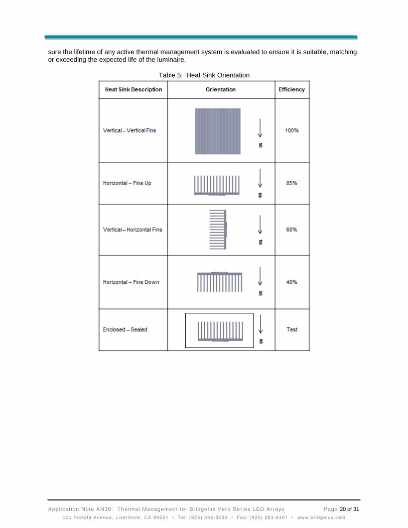
Thermal performance presented by heat sink manufacturers usually pertains to the most favorable heat sink orientation, which is with the fins of the heat sink oriented vertically (see Table 5) or in ducted flow to prevent air bypass. In the optimal orientation, hot air rises through the fins from bottom to top allowing cool air to be pulled in to the bottom. Other orientations give varying results. Rules of thumb on the impact of varying fin orientation are shown in Table 5. However, note that that the actual performance of a heat sink is dependent on many variables such as heat sink location within an assembly, the location of other heat generating elements such as a power supply, effective airflow, fin spacing, fin height, fin thickness, base thickness, base surface area, shape, fin geometry, and overall length. Consequently, the effectiveness of a heat sink mounted in varying orientations is not a fixed number and depends on the inter-relationship between many variables. A much larger poorly positioned heat sink will not be as effective as a properly oriented thermal system.
Results can vary from the guidelines listed in Table 5, and the proposed or calculated design should be measured in all orientations that will be used in the application to gauge true effectiveness of a thermal management solution. There may be many variables that cause differences in results, such as uncontrolled forced convection from central heating units and differing amount of heat conduction to surroundings. All must be taken into consideration when designing a thermal solution.
When the luminaire is to be installed into a sealed (unvented) enclosure, the system performance will be affected due to the thermal cooling capacity of the enclosure and should be tested to ensure the LED thermal requirements are being met. Enclosed configurations are typical of LED replacement lamps or bulbs in conventional enclosed luminaires. The thermal resistance of enclosed systems could be significantly improved by providing ventilation for the air to flow through the enclosure or the luminaire should be constructed in such a manner as to conduct the heat from the LED array to the exterior case of the luminaire, significantly improving the thermal performance of the system. Also, as mentioned previously, fans may be used to increase the convection heat transfer coefficient, and hence dramatically increase heat transfer from the heat sink to the ambient. If fans are used, make sure that they pull-in the cold ambient air to the heat sink surfaces and that they push hot air away from the heat sink. Also, make
Applicat ion Note AN30: Thermal Management for Bridgelux Vero Series LED Arrays Page 20 of 31
101 Portola Avenue, Livermore , CA 94551 • Tel : (925 ) 583-8400 • Fax: (925 ) 583-8401 • www.br idgelux.com
sure the lifetime of any active thermal management system is evaluated to ensure it is suitable, matching or exceeding the expected life of the luminaire.
Table 5: Heat Sink Orientation

Applicat ion Note AN30: Thermal Management for Bridgelux Vero Series LED Arrays Page 21 of 31
101 Portola Avenue, Livermore , CA 94551 • Tel : (925 ) 583-8400 • Fax: (925 ) 583-8401 • www.br idgelux.com
Types of heat sinks
Die Casting – Die castings are a common heat sink manufacturing process because of the low unit cost and the ability to have complex 3D geometries and features. The alloys used for die castings are typically of lower thermal conductivity than other processes.
Extrusion – Extrusions are another common heat sink manufacturing process due to the low tooling and unit cost. Complex 2D profiles can be extruded into various lengths and cut and finished into the final product. The fin thickness can be thin compared to casting and more surface area per volume can be achieved.
Forging – Forged heat sinks can be manufactured to have complex fin geometries similar to die castings, but the materials used are of higher thermal conductivity and the fin thickness can be smaller and more surface area per volume can be achieved.
Bonded Fin/ Stamped Fin Assemblies – These heat sinks are assemblies of fins and base plates and is used to increase the surface area by allowing for taller fins and optimized fin spacing without being constrained to manufacturing rules from die castings, extrusions, or forgings. This type of heat sink can have the most surface area per volume due to the thin stamped fins.
Mixed Metal – Mixed metal designs usually incorporate a combination of copper and aluminum, where the copper is used in the base plate to help conduct the heat to the fins more efficiently. The mixed metal approach allows for lower thermal resistance at a lower weight due to the use of aluminum for the fins.
Two Phase Flow Assemblies (heat pipes, vapor chambers, etc.) – Heat pipes and vapor chambers are based on 2 phase cooling and can be used to improve the efficiency of a heat sink by reducing conduction losses and allowing for an increase in surface area per volume and lower weight solutions.
Table 6: Heat Sink Comparison Table
Natural Convection Forced Convection
Metric Extrusions Castings
Forgings (Pin fin)
Heatpipe Fans SynJet
Weight Heavy Heavy Heavy Light Light Light
Performance Limited Limited Limited High High High
Size Large Large Large Large Small Small
Sensitive to Orientation
Yes Yes Some Minimal No No
Noise No No No No Some Some
Reliability Concerns
No No No No Some Some
Thermal Interface Material (TIM)
Although the substrate of the Vero LED module and the machined heat sink appears to be smooth, surface imperfections exist and when the LED module is mounted to the surface of a heat sink these small imperfections trap air and restrict heat from moving efficiently into the heat sink. The use of thermal interface materials, such as thermal greases (pastes), adhesives, phase change materials (PCMs) and conductive pads/films are recommended to improve the contact and heat flow from the substrate to the heat sink.

Applicat ion Note AN30: Thermal Management for Bridgelux Vero Series LED Arrays Page 22 of 31
101 Portola Avenue, Livermore , CA 94551 • Tel : (925 ) 583-8400 • Fax: (925 ) 583-8401 • www.br idgelux.com
Figure 8: Interface Between Vero LED Module and Heat Sink Mounting Surface
As shown in figure 8 above, the TIM improves the heat transfer by filling in the air voids between the array and the heat sink. There are 3 resistances in the TIM, the resistance through the TIM material and the contact resistance (remaining air layers) between the TIM surface and array and between the TIM surface and heat sink. The contact resistances dominate when the TIM does not fill in the voids such as with at thermal pad. A thermal grease or phase change material will generally fill more of the voids and have a thin bond line, thus, the contact resistance is less and the material resistance will dominate. For other materials such as pads, graphite materials, and metal TIMs the contact resistance will dominate and it will be necessary to test the TIM in order to determine the thermal resistance through the material to be sure the thermal requirements are met.
Although the contact resistance cannot be easily calculated, the thermal resistance of the TIM material can be estimated by calculating the conduction resistance through the TIM material. Equation 8, is only an estimate and should be used for materials where the contact resistance is known to be low such as that of grease or a phase change material.
Equation 8 shows the calculation for the thermal resistance of the TIM material:
RTIM = t / (k* Ac)
Equation 8: Thermal resistance of an interface material
Where:
t is the thermal interface material bond line thickness (BLT) (m)
k is the thermal conductivity (W/m-K)
Ac is the heat source contact area (m2)
TIM suppliers will often state the thermal performance as a function of area with units such as C–cm2/W.
When stated in this form, calculate the thermal resistance by dividing by the heat source contact area Ac.
RTIM = RTIM per Area / Ac
Equation 9: Calculate thermal resistance of an interface material when resistance is a function of area
Where:
RTIM per Area is the thermal resistance as a function of area (C–cm2/W)
Ac is the heat source contact area (can be assumed to be the Vero Module substrate area) (cm2)

Applicat ion Note AN30: Thermal Management for Bridgelux Vero Series LED Arrays Page 23 of 31
101 Portola Avenue, Livermore , CA 94551 • Tel : (925 ) 583-8400 • Fax: (925 ) 583-8401 • www.br idgelux.com
Types of TIMs
Grease (paste) – Thermal grease is commonly used in the electronics market for improving the thermal contact between a heat sink and heat generating component. Greases generally provide the lowest thermal resistance due to the ability of the grease to have good wetting (low contact resistance at the interfaces) and achieve thin bond lines. It is important to discuss the reliability of the grease with the supplier to ensure they are conducting testing to ensure the grease will function at high temperatures and over the life of the luminaire. Greases are typically applied manually with hand held dispensing equipment or can be stencil printed to ensure consistent and controlled application. Greases can be re-worked for products that the intent is to be field replaceable.
Thermal Adhesive/Epoxies– Thermal adhesives and epoxies can be used like a grease to get thin bond lines and good wet out of the surfaces, but the materials form a permanent bond so re-working is not possible in most cases. There could also be risks in the bond cracking due to coefficient of thermal expansion (CTE) mismatch between components.
Phase Change Material (PCM) – PCMs are a solid “polymer” like material which change from a solid to a semi-solid state at the phase change temperature. The PCM will change to a semi-solid material once it has reached the phase change temperature and will then compress (under the load of the screw) and provide good wetting and thin bond lines. PCMs can be die cut to shape, dispensed, or stencil printed like grease and PCMs can also be re-workable like grease.
Thermally conductive pads/films – Thermally conductive pads/films can be used as a TIM in applications where a higher interface resistance can be tolerated and where the use of other materials such as a grease or PCM is not desired. Although the thermal conductivity of the pad or film may be higher than grease, typically pads and films have higher interface resistances and thus the overall performance is lower than grease PCM. The advantage of pads and films are that they can be die cut for easy installation and generally are reliable over time and temperature.
Thermal adhesive tapes – Thermal tapes can be used to secure the array down to a heat sink and provide structural adhesion between the array and heat sink. Tapes generally have thermal performance like the pads and films discussed above, but also provide the structural attachment.
Metal films/foils – Metallic films and foils can be used as a thermal interface material but generally they suffer from high resistance at the interfaces. So although the thermal conductivity of the materials can be quite high compared to a grease or pad, the contact resistance dominates and the overall performance is not as good.
TIM Selection
When selecting a thermal interface material many factors must be considered. These include the TIM thermal conductivity, contact resistance, operating temperature range, cost, manufacturability, electrical conduction, and the ability to control the bond line thickness (BLT). TIM thicknesses for LED arrays typically range from 0.050 mm to 0.500 mm, depending on the type of TIM selected and material properties of the TIM. When selecting a TIM ensure that the thickness of the material is sufficient to fill gaps between the substrate and the heat sink while at the same time minimizing the final bond line thickness (BLT). Thermal conductivities and contact resistances of interface materials vary from product to product. Also, while the bulk thermal conductivity of the TIM material is important, in many cases the contact resistance (air trapped in the interfaces) is the main contributor to the overall thermal resistance, so it is best to test the TIM in the application to be sure it is performing as expected.

Applicat ion Note AN30: Thermal Management for Bridgelux Vero Series LED Arrays Page 24 of 31
101 Portola Avenue, Livermore , CA 94551 • Tel : (925 ) 583-8400 • Fax: (925 ) 583-8401 • www.br idgelux.com
Table 7: Suggested TIM Type for Vero LED Arrays (Y – okay to use) (X – not suggested)
Suggested TIM Guide
TIM Type Vero 10 Vero 13 Vero 18 Vero 29
Thermal Grease Y Y Y Y
Phase Change Y Y Y Y
Thermal Epoxy Y Y Y Y
Thermal Pad (0.5 mm max)
Y Y X X
Thermal Tape Y Y X X
Metal Foil (solid)
Y Y X X
Table 7 above shows what TIM types are acceptable to use for the Vero Modules. This table is intended to be a guide only and the product should be tested to ensure the TIM is meeting the thermal requirements as well as other requirements such as reliability, assembly, etc. Also, although the table may list a type of TIM as okay to use or not recommended, the selection should be based on the use conditions of the product. For example, if a Vero 18 or 29 is being under driven it may be feasible to use a TIM other than a grease or PCM and if a Vero 10 or 13 is being driven at the maximum current, it may be best to use a grease or PCM in order to have a low thermal resistance interface.
As mentioned above, the TIM thermal resistance (RTIM) depends on many variables and some key thermal design rules to consider:
RTIM should not exceed 20% of the thermal resistance requirement from case to ambient (Rc-a).
A grease or PCM thermal resistance can easily be below 0.1 C/W and can be used for all Vero LED Modules, however, a grease or PCM should definitely be used when the thermal power (Pth) is greater than 15 W.
Thermal Pads or Adhesive Tapes generally have a thermal resistance of ~ 1 C/W and can be used when the thermal power (Pth) is less than 15 W. Thermal pads or Adhesive Tapes can also be used for higher power dissipation devices if the total thermal resistance from case to ambient (Rc-a) is being met.
The heat sink and array surfaces can form oxides or have oils from handling or fabrication which should be removed prior to assembly with a surface cleaner such as Isopropyl alcohol.
When using a grease, the amount that is dispensed should be enough to cover the majority of the base of the substrate, but not so much as to result in a thick bond line, which will increase the thermal resistance or so much that the grease squeezes to other locations on the Vero LED Module. See table 7 below for approximate volume of grease needed for various final bond line thicknesses (BLT). These values are approximate and testing should be completed during the design phase to ensure the proper amount of grease is applied.
One method of achieving accurate volume of the TIM material is to screen print or stencil print precise quantities of a dispensable TIM on a heat sink surface prior to attaching the Vero LED Modules. TIM suppliers will provide application assistance and resources to aid in setting up the dispensing of the TIM.
A TIM should be tested under operating conditions that represent the target application to ensure the thermal requirements are being met.

Applicat ion Note AN30: Thermal Management for Bridgelux Vero Series LED Arrays Page 25 of 31
101 Portola Avenue, Livermore , CA 94551 • Tel : (925 ) 583-8400 • Fax: (925 ) 583-8401 • www.br idgelux.com
Discuss the TIM with your supplier to be sure the reliability of the TIM meets the lifetime expectations of the luminaire.
Table 8: Approximate Volume of Grease Required to Cover Substrate for Given BLT
Approximate Volume of Grease, cm3 (cc)
Final BLT, m Vero 10 Vero 13 Vero 18 Vero 29
75 0.012 0.019 0.033 0.076
100 0.016 0.025 0.044 0.101
125 0.020 0.031 0.055 0.126
150 0.023 0.037 0.066 0.152

Applicat ion Note AN30: Thermal Management for Bridgelux Vero Series LED Arrays Page 26 of 31
101 Portola Avenue, Livermore , CA 94551 • Tel : (925 ) 583-8400 • Fax: (925 ) 583-8401 • www.br idgelux.com
Measuring Effectiveness of a Thermal Solution
After a thermal management solution has been designed it is critical to experimentally validate the effectiveness of the solution. This is typically done by building a prototype, simulating the worst-case use conditions, and measuring the Vero LED Module case temperature, Tc. When simulating worst-case use conditions ensure the following:
Convection conditions are realistic.
Material properties and dimensions, including wall thicknesses, surface areas, and component sizes are representative of the design.
Surface properties, including color and roughness properties, are representative of the design.
Additional heat sources that may impact the thermal performance of the device are included (such as a power supply that is placed inside a luminaire enclosure or attached to a heat sink).
Once the representative prototype is built, and realistic use conditions are simulated, Tc may be measured to validate the design.
Special care is required when measuring the Tc to ensure an accurate measurement. As mentioned above, a Tc measurement location is provided on the top side of the Vero module for easy access in a location which Bridgelux has defined near the Light Emitting Surface (LES) and is intended for measuring the temperature with a fine gage thermocouple. This measurement location is identified in the mechanical section in the Vero LED module datasheets. The thermocouple attach area is large enough to accommodate a 30 gauge thermocouple, but a smaller gage such as 36 gauge is recommended for ease of attachment and better accuracy, see figure 9 below which shows the attachment location. The following approach is recommended to minimize measurement errors for attaching the thermocouple to the case temperature measurement point of the Vero LED Modules. A microscope will aid in the installation of the thermocouple detailed in the next steps.
Use a 36 gauge or higher (smaller wire diameter) thermocouple for measuring Tc. Thermocouples of different size and type can be found at www.omega.com. A 36 gauge K type thermocouple with connector is PN: 5SRTC-TT-K-36-36.
Attach the thermocouple bead (junction) to the measurement point surface of the Vero LED Module as shown in figures 10 - 11.
Attach the thermocouple to the Vero LED Module using a thermally conductive, but electrically non-conductive adhesive such as OmegaBond-101.
o First temporarily secure the thermocouple wire using Kapton tape to act as a strain relief and holder for the thermocouple during attachment.
o Next, bend the thermocouple wire in order to create a “spring loading” effect such that the bead will land on the prescribed area and ensure mechanical contact to the surface so that it remains in contact with the surface without an external mechanical force.
o There should be no air gaps between the thermocouple tip and the surface of the Vero LED Modules. A visual inspection using a microscope or stereo scope is beneficial when attaching the thermocouple to inspect the bead contact with the surface.
o Apply enough adhesive around the thermocouple bead to secure the thermocouple in place and allow the adhesive to cure. The adhesive should not be excessive such that it spreads to the top surface of the plastic housing or onto the LES area.
o Place a small strip of Kapton tape over the thermocouple junction to insulate the thermocouple from the surrounding air temperature and tape the wire down to the top side of the housing.

Applicat ion Note AN30: Thermal Management for Bridgelux Vero Series LED Arrays Page 27 of 31
101 Portola Avenue, Livermore , CA 94551 • Tel : (925 ) 583-8400 • Fax: (925 ) 583-8401 • www.br idgelux.com
o The wire of the thermocouple should be routed away from the LES so that the thermocouple is not in the direct path of the light emitted from the LES, see figure 11.
o If the product uses multiple Vero LED Modules in the assembly, identify the module that will be at the hottest temperature for monitoring with the thermocouple.
After turning on the Vero LED Modules, Tc will increase with time as the assembly heats up. Eventually, the lighting assembly should reach a steady state temperature. The time required to reach a steady state temperature depends on the time constant of the assembly. For small fixtures that are natural convection cooled this time is likely to be in the range of an hour. Larger fixtures could take several hours to reach steady state. It is important to monitor the temperature over time to ensure the system has reached steady state and that the Bridgelux Vero LED Modules Tc is at or below the maximum temperatures listed in the Product Data Sheet to ensure functionality and reliability.
Figure 9: Vero LED Module Showing Close up of Thermocouple Measurement Point
Figure 10: Left View Shows Thermocouple Junction Placement and
Right Shows Epoxy Placement over Junction
Tc

Applicat ion Note AN30: Thermal Management for Bridgelux Vero Series LED Arrays Page 28 of 31
101 Portola Avenue, Livermore , CA 94551 • Tel : (925 ) 583-8400 • Fax: (925 ) 583-8401 • www.br idgelux.com
Figure 11: Top View Showing Thermocouple Routing Away from LES and Kapton Strain Relief
Thermocouple wire
routing and Kapton
tape strain relief.

Applicat ion Note AN30: Thermal Management for Bridgelux Vero Series LED Arrays Page 29 of 31
101 Portola Avenue, Livermore , CA 94551 • Tel : (925 ) 583-8400 • Fax: (925 ) 583-8401 • www.br idgelux.com
Tc Correlations to True Tcase
The Tc location on the top surface of the Vero module is provided for convenient and representative measurement of the substrate temperature. However, since the Tc location is not in the direct heat flow path and is on the top surface of the Vero Module, it is at a lower temperature than the location of highest temperature on the external surface of the substrate. The location of highest temperature on the external substrate surface is located on the bottom surface of the substrate in the center of the Vero Module below the LES and is known as the True Case temperature (True Tcase), see figure 12 below. The measurement equipment which is used to characterize the value of Rj-c which is published in the Vero Module Datasheet is based on the True Tcase. Bridgelux correlates the Tc location to the True Tcase temperature under different operating conditions to ensure the Tc is representative of the True Tcase. The test method consists of an isothermal plate (Cold Plate) which is achieved by using a thermoelectric cooler (TEC) to fix the surface temperature which is measured using a thermistor in the center of the Cold Plate just beneath the center of the Vero Module. A high performance thermal grease is used as the TIM between the Vero Module and the Cold Plate to ensure good thermal contact between the Vero Module and the Cold Plate. A thermocouple is embedded into the substrate of the Vero Module to measure the True Tcase and another thermocouple is attached to the Tc measurement location. The Vero Module is operated at various drive currents and Cold Plate temperatures and the temperature difference between the True Tcase and Tc is measured. See figure 12 below for reference.
Figure 12: Tc to True Tcase Correlation Test Setup Heat travels three dimensionally and many factors contribute to the temperature gradient within the Vero Module. These factors include the Vero Module drive current, TIM, heat sink material, heat sink thermal resistance, and ambient temperature surrounding the Vero module. The Vero 10 and Vero 13 are lower power devices and the temperature difference between the Tc and True Tcase under various test conditions is typically within 5 C at nominal and maximum drive currents. The Vero 18 and Vero 29 are higher power devices and the temperature difference between Tc and True Tcase can be higher especially if an improper TIM is used or when used with a lower performance heat sink. When tested using a high performance thermal grease and mounted on the Cold Plate, the temperature difference between Tc and True Tcase for the Vero 18 and Vero 29 stayed within 5 C at nominal drive current and was within 10 C when driven at the maximum drive current. When a poor performing heat sink or a low performance TIM is used that does not allow for good heat transfer from the Vero Module into the heat sink, the temperature differences can be 20 C or higher and the Tc measurement point will not representative of the True Tcase temperature as intended. Bridgelux uses high performance thermal grease when conducting lifetime and other operational testing to ensure the Tc is representative of the True Tcase temperature.

Applicat ion Note AN30: Thermal Management for Bridgelux Vero Series LED Arrays Page 30 of 31
101 Portola Avenue, Livermore , CA 94551 • Tel : (925 ) 583-8400 • Fax: (925 ) 583-8401 • www.br idgelux.com
Design Resources
Heat Transfer Online Sources
www.electronics-cooling.com
www.coolingzone.com
www.thermalnews.com/
www.qats.com/Qpedia-Thermal-eMagazine/Current-Issue/18.aspx
www.engineeringtoolbox.com
hyperphysics.phy-astr.gsu.edu/hbase/thermo/heatra.html
www.electronics-cooling.com/1997/01/notes-on-using-thermocouples/
www.electronics-cooling.com/1995/06/how-to-select-a-heat-sink/
www.omega.com
Heat Transfer References
Incropera and DeWitt. 2002. Fundamentals of Heat and Mass Transfer 5th ed. Wiley.
Younes Shabany. 2009. Heat Transfer: Thermal Management of Electronics. CRC Press.
Adrian Bejan, George Tsatsaronis, and Michael Moran. 1996. Thermal Design & Optimization. Wiley.
Clemens Lasance and Andras Poppe. 2013. Thermal Management for LED Applications. Springer.
CFD Modeling Software
Autodesk Simulation CFD - autodesk.com/products/autodesk-simulation-family/features/simulation-cfd
Floefd - mentor.com/products/mechanical/products/floefd/
FlowTherm - mentor.com/products/mechanical/products/flotherm
Qfin & QLED - qfin.net/drupal/home
IcePak - ansys.com/Products/Simulation+Technology/Fluid+Dynamics/Specialized+Products/ANSYS+Icepak

Applicat ion Note AN30: Thermal Management for Bridgelux Vero Series LED Arrays Page 31 of 31
101 Portola Avenue, Livermore , CA 94551 • Tel : (925 ) 583-8400 • Fax: (925 ) 583-8401 • www.br idgelux.com
Disclaimer
This document has been prepared to provide reference on the application of Bridgelux LED Vero LED
Modules in customer applications. Bridgelux provides this information in good faith, but does not assume
any responsibility or liability for design deficiencies that might exist in a design provided by any company
referenced in this document.
BRIDGELUX MAKES NO REPRESENTATION OR WARRANTY WITH RESPECT TO THE ACCURACY,
APPLICABILITY, FITNESS, OR COMPLETENESS OF THE CONTENTS OF THIS DOCUMENT.
BRIDGELUX DISCLAIMS ANY WARRANTIES (EXPRESS OR IMPLIED), MERCHANTABILITY, OR
FITNESS FOR ANY PARTICULAR PURPOSE. BRIDGELUX SHALL IN NO EVENT BE HELD LIABLE TO
ANY PARTY FOR ANY DIRECT, INDIRECT, PUNITIVE, SPECIAL, INCIDENTAL OR OTHER
CONSEQUENTIAL DAMAGES ARISING DIRECTLY OR INDIRECTLY FROM ANY USE OF THIS
DOCUMENT, WHICH IS PROVIDED “AS IS.”.
It is the responsibility of the customer to ensure that the design meets all necessary requirements and
safety certifications for its intended use.
About Bridgelux
Bridgelux is a leading developer and manufacturer of technologies and solutions transforming the $40
billion global lighting industry into a $100 billion market opportunity. Based in Livermore, California,
Bridgelux is a pioneer in solid state lighting (SSL), expanding the market for light emitting diode (LED)
technologies by driving down the cost of LED lighting systems. Bridgelux’s patented light source
technology replaces traditional technologies (such as incandescent, halogen, fluorescent and high
intensity discharge lighting) with integrated, solid state lighting solutions that enable lamp and luminaire
manufacturers to provide high performance and energy efficient white light for the rapidly growing interior
and exterior lighting markets, including street lights, commercial lighting and consumer applications. With
more than 550 patent applications filed or granted worldwide, Bridgelux is the only vertically integrated
LED manufacturer and developer of solid state light sources that designs its solutions specifically for the
lighting industry. For more information about the company, please visit www.bridgelux.com.
© 2013 Bridgelux, Inc. All rights reserved. Product specifications are subject to change without notice


