Bridge Structural 00 Thom Rich
105
-
Upload
maria-jose-toste-cordeiro -
Category
Documents
-
view
224 -
download
0
Transcript of Bridge Structural 00 Thom Rich
7/30/2019 Bridge Structural 00 Thom Rich
http://slidepdf.com/reader/full/bridge-structural-00-thom-rich 1/104

7/30/2019 Bridge Structural 00 Thom Rich
http://slidepdf.com/reader/full/bridge-structural-00-thom-rich 2/104
n--n__n_n_n_n_n_n^
REESE LIBRARY
UNIVERSITY OF CALIFORNIA.
Class

7/30/2019 Bridge Structural 00 Thom Rich
http://slidepdf.com/reader/full/bridge-structural-00-thom-rich 3/104

7/30/2019 Bridge Structural 00 Thom Rich
http://slidepdf.com/reader/full/bridge-structural-00-thom-rich 4/104

7/30/2019 Bridge Structural 00 Thom Rich
http://slidepdf.com/reader/full/bridge-structural-00-thom-rich 5/104
Bridge
and Structural Design
BY
W. CHASE THOMSON,M. Can. Soc. C. E.
Assistant Engineer Dominion Bridge Co.,
Montreal, Canada.
NEW YORK :
THE ENGINEERING NEWS PUBLISHING COMPANY.
1905.

7/30/2019 Bridge Structural 00 Thom Rich
http://slidepdf.com/reader/full/bridge-structural-00-thom-rich 6/104
Copyright, 1905, by
The Engineering News Publishing Company.

7/30/2019 Bridge Structural 00 Thom Rich
http://slidepdf.com/reader/full/bridge-structural-00-thom-rich 7/104
PREFACE.
This book has been developed from lectures given by the author
during- the past five years, under the auspices of the Dominion
Bridge Co. His object has been to teach the elements of bridge
and structural design in a simple and practical manner. Arts. I to
14 inclusive treat of the general principles of design, and are illu-
strated by numerous examples ;while the remaining Articles are
examples of typical structures, in which the stresses are analyzed,
the members proportioned, and the details carefully worked out.
Both analytical and graphical methods have been employed
for obtaining stresses, and the one which seemed best suited for
any particular subjecthas been
adopted.But few tables are
given,as it was thought unnecessary to repeat information given in any
of the rolling mills' hand-books.
Although the book is intended principally for students and
draughtsmen, there are parts which may be of interest to practicing
bridge designers. Particular attention is here drawn to Art. 17,
which treats of the design of a knee-braced mill building ;and to
Art. 19 which discusses the rivet spacing and web splices in
plate girders, in which one-eighth of the web plateis
counted onas flange area.
MONTREAL, March 10, 1905.

7/30/2019 Bridge Structural 00 Thom Rich
http://slidepdf.com/reader/full/bridge-structural-00-thom-rich 8/104

7/30/2019 Bridge Structural 00 Thom Rich
http://slidepdf.com/reader/full/bridge-structural-00-thom-rich 9/104
CONTENTS.
Page
Art. I. Definitions i
2. The Composition and Resolution of Forces 2-3
3. Examples in Graphical Statics 4-6
4. The Lever and Moments 7-8
5. Shearing and Bending- Stresses in Beams 9-10
6. Moment of Resistance 1 1
7. Moment of Inertia 12
8. Radius of Gyration 13
9. Formulae Relating to Beams 14
10. Examples in the Computation of Properties of Simple
and Compound Sections 14-19
11. Examples Illustrating the Method of Determining
the Sizes of Beams 20
12. Columns and Struts 21-23
13. Examples Illustrating Method of Designing Columns
and Struts 24
14. Rivets and Riveting 25-26
15. The Complete Design of a Roof Truss for Building
with Masonry or Brick Walls Capable of With-
standing Wind Pressure 27-32
16. Roof Trusses Supported by Steel Columns 33
17. The Design of a Knee-Braced Mill Building 34-41
18. The Design of a Plate Girder 42-49
19. Plate Girder with One-Eighth of Web Plate Com-
puted as Flange Area 5O~53
20. Design for a Warren Girder Highway Bridge 54~6i
21. Design for Skew Warren Girder Highway Bridge. . .62-67
22. Design for a Pin-Connected Pratt Truss Highway
Span 68-88

7/30/2019 Bridge Structural 00 Thom Rich
http://slidepdf.com/reader/full/bridge-structural-00-thom-rich 10/104

7/30/2019 Bridge Structural 00 Thom Rich
http://slidepdf.com/reader/full/bridge-structural-00-thom-rich 11/104
BRIDGE AND STRUCTURAL DESIGN,
Bv W. CHASE THOMSON, M. Can, Soc. C. E.
ART. 1. DEFINITIONS.
Mechanics is the study of the effect of force upon matter.
Force is the action of gravity, wind, steam, etc., causing or tend-
ing to cause motion.
Matter is any substance whatever, as metal, stone, wood, water,
air, etc.
A body is any piece of matter, and its weight is the amount of
force which gravity exerts upon it.
Statics is that branch of mechanics which investigates the stresses
in a body produced by forces which keep it stationary, as in bridges
and buildings.
Dynamics, on the other hand, investigates forces which move the
body upon which they act, as in engines and other machinery.
Stress is the effect produced by equal and opposite forces, and is
measured in pounds or tons. It is equal to only one of the forces,
however. Thus, if two men pull 40 Ibs. each at opposite ends of a
rope, the stress will not be 80 Ibs., but only 40 Ibs.;and if a load of
1,000 Ibs. rest on top of a column, then the reaction of the founda-
tion on which the column rests will also be 1,000 Ibs., but the stress
in column will be equal to but one of these forces, viz.: 1,000 Ibs.
There can be no stress without a reaction which is always equal to
the force acting on body.
Tensile Stress or Tension occurs when two opposing forces tend
to pull apart the body upon which they act, as in the tie bars and
bottom chords of a bridge.
Compressive Stress or Compression occurs when the opposing
forces acting on a body tend to compress it, as in the posts and
top chords of a bridge.
7/30/2019 Bridge Structural 00 Thom Rich
http://slidepdf.com/reader/full/bridge-structural-00-thom-rich 12/104
2 BRIDGE AND STRUCTURAL DESIGN.
ART. 2. THE COMPOSITION AND RESOLUTION OF FORCES.
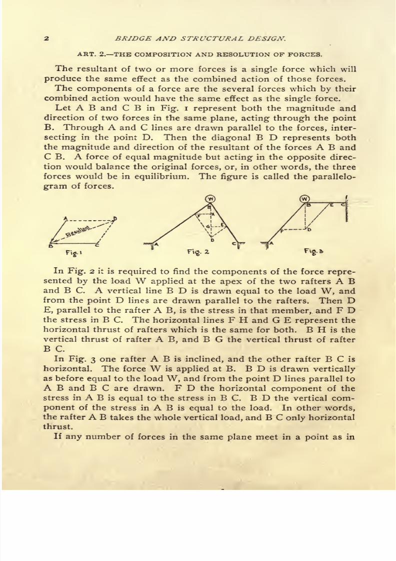
The resultant of two or more forces is a single force which will
produce the same effect as the combined action of those forces.
The components of a force are the several forces which by their
combined action would have the same effect as the single force.
Let A B and C B in Fig. i represent both the magnitude and
direction of two forces in the same plane, acting through the point
B. Through A and C lines are drawn parallel to the forces, inter-
secting in the point D. Then the diagonal B D represents both
the magnitude and direction of the resultant of the forces A B and
C B. A force of equal magnitude but acting in the opposite direc-
tion would balance the original forces, or, in other words, the three
forces would be in equilibrium. The figure is called the parallelo-
gram of forces.
Fig.Z
In Fig. 2 it is required to find the components of the force repre-
sented by the load W applied at the apex of the two rafters A Band B C. A vertical line B D is drawn equal to the load W, and
from the point D lines are drawn parallel to the rafters. Then DE, parallel to the rafter A B, is the stress in that member, and F Dthe stress in B C. The horizontal lines F H and G E represent the
horizontal thrust of rafters which is the same for both. B H is the
vertical thrust of rafter A B, and B G the vertical thrust of rafter
B C.
In Fig. 3 one rafter A B is inclined, and the other rafter B C is
horizontal. The force W is applied at B. B D is drawn vertically
as before equal to the load W, and from the point D lines parallel to
A B and B C are drawn. F D the horizontal component of the
stress in A B is equal to the stress in B C. B D the vertical com-
ponent of the stress in A B is equal to the load. In other words,
the rafter A B takes the whole vertical load, and B C only horizontal
thrust.
If any number of forces in the same plane meet in a point as in

7/30/2019 Bridge Structural 00 Thom Rich
http://slidepdf.com/reader/full/bridge-structural-00-thom-rich 13/104
THE COMPOSITION AND RESOLUTION OF.FORCES.
Fig. 4, their resultant may be found by drawing lines end to end
equal and parallel to the forces as in Fig. 4a. The closing line rep-
resents the magnitude and direction of the resultant. This diagramis called the polygon of forces. The arrow heads represent the
direction of the forces and follow each other around the diagram.
The resultant, however, always acts towards the last force drawn.
A force equal to the resultant but acting in the opposite direction
would hold the other forces in equilibrium.
If any number of forces in the same plane and acting through the
same point are in equilibrium, their force polygon will form a closed
figure, and if the direction of all the forces be known and the mag-nitude of all but two, these may be found by scale from the force
C 75-
^B
fig. 5
polygon. This case is similar to the forces acting at the panel
points of a bridge or roof truss, and the principle enables one to
find the stresses in all the members of a framed structure by the
graphical method.
In Fig. 5 there are five forces acting through the same point
which are denoted by the letters between which they lie. This is
the usual and undoubtedly the best method of denoting stresses
when solving them by the graphical method. The stresses A B =5,000 Ibs., B C = 12,000 Ibs. and C D 25,000 Ibs. are given, and the
direction only of D E and E A.
Fig. 5a is the force polygon which is constructed by drawing
lines parallel and equal to the forces A B, B C and C D. From the
point d in force polygon a line is drawn parallel to the force D Ebut of indefinite length ;
another line is drawn from the point a par-
allel to E A. The intersection of the two lines in the point e deter-

7/30/2019 Bridge Structural 00 Thom Rich
http://slidepdf.com/reader/full/bridge-structural-00-thom-rich 14/104
4 BRIDGE AND STRUCTURAL DESIGN,
mines the magnitude of the forces D E and E A. D E is about
9,000 Ibs. and E A about 35,000 Ibs. Any force acting away from
the point indicates tension, and any force acting towards it, com-
pression.
ART. 3. EXAMPLES IN GRAPHICAL STATICS.
Fig. 6 represents a simple roof truss. The span is 20 ft. depth at
centre 5 ft., and trusses spaced 10 ft., centre to centre. Assumed
load 50 Ibs. per square foot of horizontal projection, concentrated
at panel points by purlins. The total load on truss will be 20' x 10'
x 50 Ibs.
= 10,000 Ibs. The load at each intermediate panel point
10,000= =
2,500 Ibs., and at each end panel point, one-half of
4
this amount = 1,250 Ibs. The end panel loads are carried directly
by the walls, and therefore have no effect on the stresses in the
truss. Capital letters are used to denote the external forces which
consist of loads and the reactions of the end supports ;and small
letters for the internal forces. The truss members are indicated bythe letters between which they lie.
Fig. 6a is the stress diagram. Beginning at the left hand end of
truss and going around it in a right handed direction, as indicated
by curved arrow, the forces A B, B C, C D, D E and E F are laid
off downwards on the vertical load line, Fig. 6a. The next external
force is the reaction of the right-hand support equal to one-half
the load on span. This force is laid off upwards from F to G as it
acts in the opposite direction to the loads. Finally, the reaction of
the left-hand support is laid off from G to A the point of beginning.
Now, at the left-hand end of truss there are four forces meeting in a
point. Two of these forces, the reaction G A and the load A B are
known;and two forces, the stresses in rafter Bb and bottom chord
bG, are unknown. From the point B on load line, a line is drawn
parallel with the rafter Bb, and from G, a line parallel with the bot-
tom chord bG. These two lines intersect in the point b, and deter-
mine the stresses Bb and bG. Next, at the first panel point fromthe end, the stress in bB has just been found, the load BC is known
and the stresses in Cc and cb unknown. From the point C on load
line, a line is drawn parallel to the rafter Cc, and from the point b in
stress diagram, a line parallel to the strut cb. The two intersect in
the point e, and determine the stresses in Cc and cb. At the apex

7/30/2019 Bridge Structural 00 Thom Rich
http://slidepdf.com/reader/full/bridge-structural-00-thom-rich 15/104
EXAMPLES IN GRAPHICAL STA TTCS.
of rafters there are now two unknown forces, the stresses in Dd
and dc. From the point D on load line, a line is drawn parallel to
Dd, and from the point c in stress diagram, a line parallel to dc.
The two intersect in the point d and determine the stresses in Dd
and dc.
It is unnecessary -to proceed any further with the stress diagram,
as the stresses in the right-hand end of truss will evidently be the
same as those in the left-hand end, but to test the accuracy of the
work it is sometimes advisable to go through the whole truss, and
if the work has been carefully done the stress diagram will form a
closed figure.
Now to know whether a member is in compression or tension, it
is necessary to observe which way the stresses act in the stress dia-
gram. In going around any panel point in the direction in which
the external forces have been taken (in this case from left to right)
if a force in the stress diagram acts towards the panel point, the
member is in compression, and if away from it, in tension. For ex-
ample:
At the apex of rafters, going aroundthe
point fromleft to
right, and observing the direction of the forces in the stress dia-
gram, it will be seen that cC acts towards the point, and therefore
the stress in rafter cC is compression ;the load C D acts towards
the point, and the force Dd acts towards it. The next force dc acts
away from the point, and so the stress dc is tension.
The external forces and stresses are shown on the truss diagram,

7/30/2019 Bridge Structural 00 Thom Rich
http://slidepdf.com/reader/full/bridge-structural-00-thom-rich 16/104
6 BRIDGE AND STRUCTURAL DESIGN.
Fig. 6. The sign (-f)indicates compression, and the sign ( )
tension.
One of the commonest forms of roof trusses is that known as theFink Truss, so-called from the name of the inventor. Fig. 7 is an
example.
The span is 40 ft., the angle of roof with horizontal 30, the panel
load 2,500 Ibs. The half-panel loads at the ends have been omitted,
as they have no effect on the stresses. Beginning at the left-hand
end of truss, as in previous example, the loads A to H are laid off
on the load line in Fig. 7a downwards, and the reactions H I and
I A upwards to the point of beginning. The stress diagram is then
proceeded with, beginning at left end. At panel point B C a slight
difficulty is encountered, where there are three unknown forces, viz.,
Cc, cc, and c t b, and the diagram cannot be completed when there
are more than two unknown. At the lower end of strut b, c, the
same difficulty is met with. A very nice method of solving this
problem is to change some of the web members temporarily as in
Fig. 8, from which the stress diagram, Fig. 8a, is obtained, and the
stress in the bottom chord member i I. The web members maythen be changed back to their original form, and the polygon of
forces completed for the panel point at lower end of strut b, dwhere there are now only two unknown forces, viz., b
l C, and c, i.

7/30/2019 Bridge Structural 00 Thom Rich
http://slidepdf.com/reader/full/bridge-structural-00-thom-rich 17/104
THE LEVER AND MOMENTS. 7
After which the polygon of forces for panel point B C may be
drawn. The rest is simple.
When the truss is
symmetricaland the
panel
loads equal, as in
the present example, there is no difficulty in constructing the stress
diagram, as the points a, b, c, d will always lie in a straight line;
but if the panel lengths or the loads are unequal, as is sometimes
the case, it will be necessary to use some method for finding an
extra force either at the upper or lower end of strut b, ct .
One-half of the stress diagram only has been constructed, as the
other half would be exactly the same.
A common formof roof truss is
shownin
Fig. 9. The spanis
50ft., centre to centre, the depth at ends 4 ft. and at centre 6 ft. The
intermediate panel loads are 2,500 Ibs. each, and the end panel loads
1,250 Ibs. each.
Fig. Qa is the stress diagram which is only constructed for one-
half the truss. There is no stress in the end panels of bottom chord
oM and 5M from the vertical loads. These members are required
for lateral stability.
Sometimes a roof truss is required to slope in one direction onlyas in Fig. 10. The stresses are found in the same manner as before,
but it is necessary to make the stress diagram for the whole truss.
The span is 40 ft. the depth at one end 4 ft. and at the other end
8 ft. The intermediate panel loads are 2,500 Ibs. each, and the end
panel loads 1,250 Ibs. each.
ART. 4. THE LEVER AND MOMENTS.
If a force act on a body tending to rotate it about a certain point,
it is said to have a moment about that point equal to the amount of
the force multiplied by the perpendicular distance from the line of
action of force to the said point.
In Fig. ii the force F acts about the point a with a leverage
equal to ab. The point a is called the point of moments, and the
distance ab the lever arm.
There may be two or more forces tending to rotate a body aboutthe same point either in the same or in the opposite direction
;and
if the body is in equilibrium the sum of the left-hand moments must
be equal to the sum of the right-hand moments. Fig. 12 represents
a beam supported at the point B. The load at A tends to rotate
the beam in a left-handed direction about its point of support, and

7/30/2019 Bridge Structural 00 Thom Rich
http://slidepdf.com/reader/full/bridge-structural-00-thom-rich 18/104
8 BRIDGE AND STRUCTURAL DESIGN.
its moment = 3 Ibs. x 10' = 30 ft.-lbs. The load at C tends to ro-
tate the beam in a right-handed direction, and its moment = 5 Ibs.
x 6'=30
ft.-lbs. Themoments,
therefore, are
equal
butopposite,
so the beams will remain horizontal. A lever may either be straight
or bent, but no matter what the actual length of the lever may be
the true lever arm is the perpendicular distance from the line of
force to the point of moments. Figs. 13 and 14 are examples of
bent levers.
Fig. 15 represents a bracket on the side of a wall supporting a
load W at the point B. The principle of the lever is here employed
Fig.M
\vtt* arm*
levgf arm Mgvetar
Pg^^/x^wt^/X,^^^^^' :
FifctG fig. 17
to determine the stresses. For the stress in A B moments are taken
about the point C, then W X lever arm C E = stress in A B X lever
arm A C. Therefore stress in A B =W xC E
A CFor the stress
in C B moments are taken about the point A. ThenWX lever arm
A B = stress in C BX lever arm A D. Therefore stress in C B =
W x A B
A DTo determine the reactions for a beam supported at both ends and

7/30/2019 Bridge Structural 00 Thom Rich
http://slidepdf.com/reader/full/bridge-structural-00-thom-rich 19/104
SHEARING AND BENDING STRESSES IN BEAMS. g
loaded in any manner, moments of all the loads are taken about one
support, and divided by the distance centre to centre of supports.
Example : On the beam A B, Fig. 16, there are four loads placed
as shown. For the reaction at A moments are taken about B and
divided by the span as follows :
5,ooox 2= 10,000
2,000 x 7= 14,000
4,000 x 10= 40,000
3,500 x 14= 49,000
113,000 ft.-lbs. -f- 17'=
6,647 Iks.
The loads tend to rotate the beam about the point B in a left-
hand direction with a moment of 113,000 ft.-lbs. The reaction at Atends to rotate the beam about the point B in a right-handed direc-
tion with a moment 6,647 Ibs. x 17'= 1 13,000 ft.-lbs. These mo-
ments are equal but opposite, and therefore counteract each other,
so there is no resultant moment at the support B.
To obtain the reaction B, moments may be taken about A, but
as the sum of the reactions must be equal to the sum of the loads, it
is only necessary to add together the loads, and subtract the reac-
tion A. The result will be the reaction B, thus :
5,000 + 2,000 + 4,000 + 3,500 6,647 = 7>853 reaction B.
ART. 5. SHEARING AND BENDING STRESSES IN BEAMS.
A loaded beam is subjected to two kinds of stress, viz. : Shearingand bending. The shearing stress tends to cause the particles of
the beam to slide by one another in a vertical plane, as when a plate
is cut in a shearing machine. Fig. 17 represents a beam loaded
uniformly with a load = w per lineal foot. At each end there are
equal and opposite forces acting on the beam, viz., one-half of the
load acting downwards, -and the reaction of the support acting up-
w 1
wards, each equal to . These two forces tend to shear the
2
beam, or cut it crosswise. The shearing force at any point, distant
x from one end, is equal to the reaction at that end, less the load on
w 1
the length x; or, shear at x = w x. The bending stresses
2
cause compression on the upper side of the beam and tension on the

7/30/2019 Bridge Structural 00 Thom Rich
http://slidepdf.com/reader/full/bridge-structural-00-thom-rich 20/104
10 BRIDGE AND STRUCTURAL DESIGN.
Bamsuppotted
and fid d\ Ooe end,and
a load VI at olher end.
momnt Diagram.Max.momnt isal fixed nd, -VYl
Momcrf alany point
cTtatanl x from toad Htx
Fig.is^ . Shear D*iagram. Shear at any poirtf
VI.
Fig. 19. Beam supported and fixed al one end. and
carryinga toad to-
perlineal foot.
Fig.idS. MomentDiagram. .,.
Ma*. Moment s al fwed end. T*"1-
Moment at any point distant jt from ffw ?nd ^5
The curve is a parabola with vertex a| free end.
Fid. t9fc. Shear Diagram.Max. Shear is al fixed end. u>.
Shear atany point distant x from free end.ifx
X -
_^_Fi.2o. Beam
supported at bof* end, an* carnlna aconcentrated load W at centre.
Fig 2ol. Moment Diagram. .
Max.Moment is at centre.* *$?:
Moment atany point
x between end and cenfte. ^
Fi$.2* Shear Dfeg<*.
Fig.21. Beam suppotted at both ends and
carryinga
uniform load UPper lineal foot.
FiA2ia. Moment Diagram. ^Max. Moment \s at centre. -^r~.
Moment at any point distant x' from support.
The curve is a parabola *ith vertex at cento.
Fig.2i&. Shear Diagram.Max, shear at ends . ^*. ..
Shear at any point distant % from support,^-wShear at centre .o.

7/30/2019 Bridge Structural 00 Thom Rich
http://slidepdf.com/reader/full/bridge-structural-00-thom-rich 21/104
MOMENT OF RESISTANCE. 1 1
lower side. In the case of an open girder the bending moment is
all resisted by the flanges ; but, in a solid beam, it is resisted by the
entire section.
Bending moments and shears for various cases are illustrated in
Figs. 18, 19, 20 and 21.
ART. 6. MOMENT OF RESISTANCE.
When a beam is loaded transversely, the fibres on one side of the
neutral axis are compressed and those on the other side extended,
while the fibres in the neutral axis are neither compressed nor ex-
tended, and the beam will assume a curved form as in Fig. 22. Theextreme outer fibres are stressed most, and the intermediate ones
in direct proportion to their distance from the axis.
Fig.22
The moment of resistance of a /eam is the moment of all the
fibre stresses about the neutral axis.
The following is a general method for determining the moment
of resistance of a beam of any section :
In Fig. 23. f= stress per square inch on outer fibres.
n = distance in inches from neutral axis to outer fibres.
y=
distance in inches from neutral axis to any fibre.A =a small or elementary area.
Then = stress per square inch on fibres at distance of onen
inch from neutral axis.
y= stress per square inch on fibres at distance of yn
from neutral axis.
y A = stress on an element of fibres at distance of yn
from neutral axis.
f yA )y=moment of stress on an element of fibres
x n
at distance of y from neutral axis.

7/30/2019 Bridge Structural 00 Thom Rich
http://slidepdf.com/reader/full/bridge-structural-00-thom-rich 22/104
12 BRIDGE AND STRUCTURAL DESIGN.
This last expression taken for all values of y both above and
below the neutral axis is the moment of stress (or moment of re-
sistance) of the given section, or
n n
The factor (2>y
2A) is called the moment of inertia and is repre-
sented by I. It is obtained by multiplying: each elementary area
by the square of its distance from the neutral axis and taking: the
sum of the products.
Representing: (^y2
^) by I, then M= I=moment of resistance.n
The factor( )
of the moment of resistance is usually representedvn '
by R and called the moment of resistance, which is not strictly
correct, for the real moment of resistance =Rf.
I
is sometimes called the section modulus and represented by S.n
The outer fibres only of a beam receive the maximum stress per
square inch, hence the more metal concentrated in the flange, the
greater its resistance to bending.
ART. 7. MOMENT OF INERTIA.
As stated in Art. 6, the moment of inertia is a factor of the mo-
ment of resistance, and is represented by I. The following is an ap-
proximate method for finding the moment of inertia of a beam of
any section about an axis through its centre of gravity.
The section should be divided into a number of narrow strips
parallel with the neutral axis, the area of each strip calculated, and
the distance of its centre line from the neutral axis measured. Each
area should be multiplied by the square -of its distance from the
neutral axis, then the sum of these products will be the approxi-
mate moment of inertia. The narrower the strips, the more ac-
curate will be the result, but it will always be a trifle too small. Tobe exact, the moment of inertia of each strip about an axis through
its own centre of gravity should be added to the last result but
this is unnecessary in practice.
For the moment of inertia of a rectangle about an axis through
its centre of gravity, the section is supposed to be divided into nar-

7/30/2019 Bridge Structural 00 Thom Rich
http://slidepdf.com/reader/full/bridge-structural-00-thom-rich 23/104
RADIUS OF G YRA TION.
.. 5 J
row strips as shown in Fig. 24. The length of each strip is b, its
thickness=A>and the distance of its centre from the neutral axis
=y-
Then the summation of (bAy2)=the approximate moment of
inertia.
By the help of the calculus, the thickness of each strip can be
made infinitely small and therefore an exact result obtained which
bh 3
is I-- . In which b = the width of beam and h = the height.12
This is important.
The moment of inertia of a triangle about an axis through its
centre of
gravityand
parallelwith the
base,as shown in
Fig. 25,
is
The moment of inertia of a circle about an axis through its centre
Tfd4
of gravity, as shown in Fig. 26 is I .
64The moment of inertia of a compound section about an axis
through its centre of gravity is equal to the sum of the moments of
inertia of the component parts about axes through their own centres
of gravity, plus the areas of the component parts multiplied by the
squares of the distances of their centrestof gravity from the neutral
axis of the whole figure.
ART. 8. RADIUS OF GYRATION.
The radius of gyration, which is usually represented by r, is the
distance from the neutral axis through the centre of gravity of a
section to a point where, if the toial area could be concentrated and
multiplied by the square of this distance, the result would be the
moment of inertia of the section about the same axis;thus I = area
X r2
, and therefore r= \- The radius of gyration is usedarea
principally in formulas for the strength of columns.

7/30/2019 Bridge Structural 00 Thom Rich
http://slidepdf.com/reader/full/bridge-structural-00-thom-rich 24/104
14 BRIDGE AND STRUCTURAL DESIGN.
ART. 9. FORMULAE RELATING TO BEAMS.
The following notation and relations between bending moments
and the various properties of beams, which have already been
treated of in Arts. 6, 7 and 8, are here set forth more concisely.
The student should familiarize himself with the formulae as they
will be referred to frequently in the following pages :
M = bending moment in inch-pounds.
R = moment of resistance, = S. the section modulus.
f = stress per square inch on outer fibres.
I moment of inertia about axis through centre of gravity of
section.
A = area of section.
n = distance from centre of gravity of section to extreme outer
fibres,
r = radius of gyration.
Then M = Rf.
ART. 10. EXAMPLES IN THE COMPUTATION OF PROPERTIES OF SIMPLE
AND COMPOUND SECTIONS.
Fig. 2,7 represents a 6 X 3^ X ^ angle. It is divided into two
rectangles: one 6" X .5"=
30", and one 3" X .5"=
1.5". To
find the position of the axis ab through the center of gravity,
moments of the areas are taken about the back of the shorter leg as
follows;
Areas, Levers. Moments.
i. S;;x
25"=
.375
3.0 x 3."=
9.000
4.5" 9.375

7/30/2019 Bridge Structural 00 Thom Rich
http://slidepdf.com/reader/full/bridge-structural-00-thom-rich 25/104
COMPUTATION OF PROPERTIES OF SECTIONS.
Then dividing the total moment by the total area, the distance of
the centre of gravity from the point of moments is obtained thus :
9,375 -*- 4-5 = 2.08".
For the position of the axis cd moments are taken about the
back of the longer flange, and divided by the area as before.
Areas. Levere. Moments.evere.
.25"=
.75
.2 3-00
4-5D"
3-75
Then 375 -f- 4.5 = .833", which is the distance from the back of
longer leg to the axi^ cd. The moment of inertia about axis ab
will be computed as follows :
bh 3.5X6
3
I for rectangle (6" X .5")= =- =
9.0012 12
bh 3 ^X tj3
I for rectangle (a"X .5")= = =
.0312 12
3.0 D" X .Q22
= 2.54
1.5" X 1.83'= 5.02
I ab =16.59
16.59 /T~ /16.59=
4-23, rab = -*/ = */-- =1.92.
*3-92 A 4.5
The moment of inertia, moment of resistance and radius of gyra-
tion about axis cd are found similarly.
ft]Vcfdf Wa^e
* 7* ^
Fig.28
7/30/2019 Bridge Structural 00 Thom Rich
http://slidepdf.com/reader/full/bridge-structural-00-thom-rich 26/104
16 BRIDGE AND STRUCTURAL DESIGN.
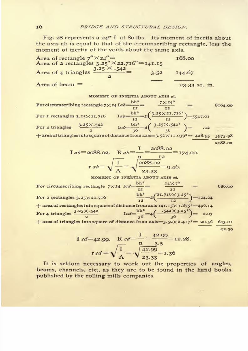
Fig. 28 represents a 24" I at 80 Ibs. Its moment of inertia about
the axis ab is equal to that of the circumscribing rectangle, less the
moment of inertia of the voids about the same axis.
Area of rectangle 7" X 24"=
1 68.00
Area of 2 rectangles 3.25" X 22.716"= 141. 15
3.25 X .542Area of 4 triangles
=3.52 144.67
Area of beam 23.33 SQ- in.
MOMENT OF INERTIA ABOUT AXIS 06.
bh 37X24
3
For circumscribing rectangle 7X 24!&= = =8064.oo
bh 8/3. 25x21. 7i6
3\
For 2 rectangles 3.25x21.716 \ab= =2\
~j=5547-Oi
3.25X-542 bh 3 / 3.25X-5423
\For 4 triangles Ia&= =41 - )= .02
2 36 V 36 /
-j- area of triangles into square of distance from axis 3. 52X 1 1-O398=
428. 95 5975 . 98
2088.02
I 2088.02
=174.00.
23-33
MOMENT OF INERTIA ABOUT AXIS cd.
bh 824X7 3
For circumscribing rectangle 7x24 Icd=-= - = 686.00
bh 3 /2i. 716x3.253\
For 2 rectangles 3.25x21.716 -=2!
-1=124.24
-f-area of rectangles into square of distance from axis 141.15x1.875*=496. 14
3.25X-542 . bh 8 / .542x3.25^For 4 triangles
^ -- - lcd= =4! ^-^ )= 2.072 36 \ 36 /
-f- area of triangles into square of distance from axis=3.52X2.4i72=
20.56 643.01
42.99
I 42.99
I #/=42.99. R cd
=--=12.28.n
_3-5
1 42.99=1.36
A H 23.33
It is seldom necessary to work out the properties of angles,
beams, channels, etc., as they are to be found in the hand books
published by the rolling mills companies.

7/30/2019 Bridge Structural 00 Thom Rich
http://slidepdf.com/reader/full/bridge-structural-00-thom-rich 27/104
COMPUTATION OF PROPERTIES OF SECTIONS.
The following table gives the properties of three special German
beams with wide flanges, used principally for columns.
Theywill
be referred to again in the following pages :
Fig. 29.
Description Area Wt. lab led Hob Red ra& red
5.25 17.5 23.22 6.41 9.07 2.81 2.12 i. ii
7.00 23.3 44.90 II.01 14.72 4.32 2.55 1.258.60 29.0 96.50 15.50 23.89 5.40 3.35 1.34
Fig.30 Fig.
31
. 30 represents a chord section composed of
two 15" [s.
one 24 X }
$ 33lbs=
19.80
plate = 12.oo
31.80"
To find the position of the axis ab through the centre of gravity
of the section, the simplest method is to take moments of the areas
about the centre line of the channels and divide by the total area.
The result will be the distance from the centre line of channels to
the axis ab, thus :
Areas. Levers. Moments.
Channels
Plate
Totals
19.80" X o =X7-75
~o
93
93
then93
31-80
nel to axis ad.
=2.92", which is the distance from centre line of chan-

7/30/2019 Bridge Structural 00 Thom Rich
http://slidepdf.com/reader/full/bridge-structural-00-thom-rich 28/104
18 BRIDGE AND STRUCTURAL DESIGN.
MOMENT OP INERTIA ABOUT AXIS ab.
bh s24X-5*
I for
24XJ4 plateabout its center of
gravity
= = =.25
Area of plate into square of distance of its centre of gravity
from axis ab =i2.oX4-83
8=28o.2o
Ifor2.i5"[s@33lbsabouttheircentreofgravity(fromCarnegie)= 2x312.6 =625.20
Area of channels into square of distance of their centre of
gravity from axis =i9.8oX2.928=i68.82
1074.47
I 1074.4700=1074.47. R ab =
=103.1.
n 10.42
I 1074-47
o""^ 5 'Si -
31.80
MOMENT OF INERTIA ABOUT AXIS cd.
bh 8.5x24'
I for 24X% plate about its centre of gravity= = =
576.00
I fora. 15 [s@33lbs about their centre ofgravity(fromCarnegie)= 2x8.23= 16.46
Area of channels into square of distance of their centre of
gravity from axis =19.8X9-29s=1708. 82
2301.28
I 2301.281^=2301.28. Rr</ = = =
191.77.
Fig. 31 represents a chord section composed of
1 cover plate 24 X ^ =12.00
2 web plates i6X}4 =16.00
4 angles 6X3>X^ =18.00
46.00"
To find the position of the axis ad moments of the areas are taken
about the centre line of the webs thus :
Areas Levers MomentsWeb plates and angles 34" X o = o
Cover plates 12 a" X 8.25=
99
Totals 46" 99
99then =
2.15", which is the distance from centre line of web plates
46
to axis ab.

7/30/2019 Bridge Structural 00 Thom Rich
http://slidepdf.com/reader/full/bridge-structural-00-thom-rich 29/104
COMPUTATION OF PROPERTIES OF SECTIONS. 19
The location of centre of gravity of angles is obtained from
Carnegie.
MOMENT OF INERTIA ABOUT AXIS 06.
bh 324X 5*
I for 24XK cover plate about us centre of gravity=-=-
=-*5
bh8 IXI6 8
I for 2.i6x> web plates about their centre of gravity=-=- =341.34
I for 4-6X3^XK angles about their centre of gravity (from
Carnegie) =4X16.59 = 66.36
Area of cover plate into square of distance of its centre of grav-
ity from axis =12.0X6.10*= 446.52
Area of web plates into square of distance of their centre of
gravity from axis =16.0X2.15*= 73.96
Area of upper angles into square of distance of their centre of
gravity from axis = 9-oX3-772=
127.92
Area of lower angles into square of distance of their center of
gravity from axis = 9.0x8.07*= 586.12
1642.47
I 1642.471^=1642.47. Rad= = =161.81.
_n 10.15
I / 16,.=
5.98.
MOMENT OF INERTIA ABOUT AXIS L
bh 8. 5X24
8
I for 24XK cover plate about its centre of gravity =-
= = 576.00
bh 8I6X-5
8
I for 2.i6x Y* web plates about their centre of gravity= = =
.37
I for 4.6X3>X> angles about their centre of gravity (from
Carnegie)= 4X4-25 = 17.00
Area of web plates into square of distance of their centre of
gravity from axis =i6.ox8.252=io89.oo
Area of angles into square of distance of their centre of
gravity from axis =i8.oX9-338=i566.88
3249.25
. I 3249.25I <:</= 3249.25. R cd= =
=270.77n 12
I/ 3249.25

7/30/2019 Bridge Structural 00 Thom Rich
http://slidepdf.com/reader/full/bridge-structural-00-thom-rich 30/104
20 BRIDGE AND STRUCTURAL DESIGN.
ART. 11. EXAMPLES ILLUSTRATING THE METHOD OF DETERMINING THESIZES OF BEAMS REQUIRED FOR VARIOUS CASES. THE MAXIMUMFIBRE STRESS NOT TO EXCEED 15,000 LBS. PER SQ. IN.
Fig:. 32 represents a cantilever beam with a concentrated load of
3,000 Ibs. 10 ft. from point of support. M= 3,000 X 10 = 30,000
ft.-lbs. 30,000X12=360,000 inch-lbs.
M 360,000R= =
24. Turning: to the table of I-beams in Car-f 15,000
negfie, it will be found that a 10" I @ 25 Ibs has a moment of resist-
ance (or section modulus) of 24.4. This is the beam required.
Fi 36
Fig:. 33 represents a cantilever beam, projecting: 12 ft. from a wall,
and loaded with a uniform load of 500 Ibs. per lineal foot.
500XI22
M
-=
36,000ft.-lbs.
36,000 X 12
=432,000 inch-lbs.12
432,000R = ---= 28.8. This case requires a 12" I @ 31.5 Ibs. R=36.
15,000
Fig. 34 represents a beam of 2O-ft. span, with a centre load of
15,000 Ibs.
15,000X20M =---- =
75,000 ft. Ibs. 75,000 X 12 =900,000 inch-lbs.
4
is case requires a 15" I @ 45 Ibs. R=6o.8. 15,000
Fig:. 35 represents a beam of 20 ft. span, with a uniform load of
600 Ibs. per foot.
600X2O 2
M = ---=30,000 ft.-lbs. 30,000 X 12 = 360,000 inch-lbs.
8

7/30/2019 Bridge Structural 00 Thom Rich
http://slidepdf.com/reader/full/bridge-structural-00-thom-rich 31/104
COLUMNS AND STRUTS. 21
36o,OOOR =
=24. This requires a 10 I @ 25 Ibs. R=24.4.
15,000Fig-. 36 represents a beam of 20 ft. span loaded unevenly as shown.
For the reaction at A, moments are taken about B, thus
4,000X 5=20,000
7,000X 9=63,000
3,000X16=48,000
131,ooo ft.lbs. then 131,000-^-20=6,550 Ibs.= reaction at A.
The maximum bending- moment will be under the 7,000 Ibs. load.The reaction A acts with a lever arm about this point of n ft.
tending: to cause rotation in a right handed direction, and the load
Fig.37
Fig.38
of 3,000 Ibs. acts with a lever arm of 7 ft. about the same point
tending to cause rotation in a left handed direction, as indicated by
curved arrows. ThenM = 6,550 Ibs. X n' 3,000 Ibs. X / = 51,050
612,600ft.-lbs. 51,050 X 12 = 612,600 inch-lbs. R= =
40.8. This
15,000
case requires a 15" I @ 42 Ibs. R =58.9.
No beam should be used where the span exceeds twenty times the
width of the flange unless supported laterally. Floor beams and
stringers in buildings are usually stayed at much closer intervals,
either
byother beams
framinginto them or
directly bythe floor.
ART. 12. COLUMNS AND STRUTS.
A column or strut may fail by crushing, by bending or by both
combined. A short column will sustain a greater load than a long
one of the same section, and a column with fixed (or square) ends,
more than one with hinged (or pin) ends. Columns are usually divi-
7/30/2019 Bridge Structural 00 Thom Rich
http://slidepdf.com/reader/full/bridge-structural-00-thom-rich 32/104
22 BRIDGE AND STRUCTURAL DESIGN.
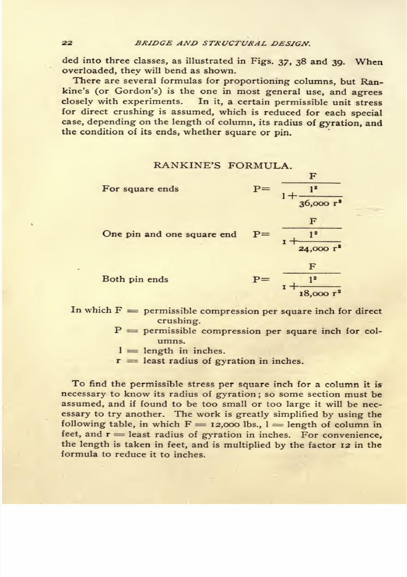
ded into three classes, as illustrated in Figs. 37, 38 and 39. Whenoverloaded, they will bend as shown.
There are several formulas for proportioning columns, but Ran-
kine's (or Gordon's) is the one in most general use, and agrees
closely with experiments. In it, a certain permissible unit stress
for direct crushing is assumed, which is reduced for each special
case, depending on the length of column, its radius of gyration, and
the condition of its ends, whether square or pin.
RANKINE'S FORMULA.
For square ends P=
36,000 rg
F
One pin and one square end P=I
Both pin ends P=
24,000 r*
F
I2
18,000 r2
In which F = permissible compression per square inch for direct
crushing.
P = permissible compression per square inch for col-
umns.
1 = length in inches,
r = least radius of gyration in inches.
To find the permissible stress per square inch for a column it is
necessary to know its radius of gyration ; so some section must beassumed, and if found to be too small or too large it will be nec-
essary to try another. The work is greatly simplified by using the
following table, in which F = 12,000 Ibs., 1 = length of column in
feet, and r = least radius of gyration in inches. For convenience,
the length is taken in feet, and is multiplied by the factor 12 in the
formula to reduce it to inches.

7/30/2019 Bridge Structural 00 Thom Rich
http://slidepdf.com/reader/full/bridge-structural-00-thom-rich 33/104
COLUMNS AND STRUTS.
PERMISSIBLE COMPRESSION PER SQ. INCH FOR COLUMNS12,000 LBS. REDUCED BY RANKINE'S FORMULA
Square Ends Pin and Square Ends Pin Ends
I2OOO I2OOO I2OOOO
36000 r* 24000 r' 18000
1

7/30/2019 Bridge Structural 00 Thom Rich
http://slidepdf.com/reader/full/bridge-structural-00-thom-rich 34/104
24 BRIDGE AND STRUCTURAL DESIGN.
The same table may be used for any other value of F (say 15,000),
for example: If 10,000 Ibs. per square inch be the permissible stress
when the factor F= 12,000, then io,oooX = 12,500 Ibs. per12,000
square inch is the permissible stress when the factor F =15,000.
Columns in building are usually figured as though they had pin
ends, which is an error on the safe side and compensates to a cer-
tain extent for eccentric loading and any slight unevenness in the
foundation. The end sections of top chords in pin-connected
bridges are usually figured as "square and pin end" columns, and
the intermediate sections as square end columns. The posts are
usually figured as "pin end" columns whether connected by pins
or otherwise. These rules are not always adhered to and one must
be guided by the specification under which the structure is to be
designed.
ART. 13. EXAMPLES ILLUSTRATING METHOD OP DESIGNING COLUMNSAND STRUTS.
A column 20 ft. long is required to support a load of 150,000 Ibs.
Unit stress, 12,000 Ibs., reduced for pin ends by Rankine's formula.
Fig. 40 represents a trial section consisting of :
i 6^X5^ XYs I @ 23.3 Ibs.= 7.00 (Table Art. 10.)
2 10" [s @ 15 Ibs. 8.92 (Carnegie)
15.92 square inches.
For the least radius of gyration :
I ab=(ior 2.io"[s. See Carnegie) 66.9X2=133.80
(for 6^X5^ I. See table Art. i o) n.oi
144.81
/"T=
<\=
*lab = <\
= A/- =
3-0215.90

7/30/2019 Bridge Structural 00 Thom Rich
http://slidepdf.com/reader/full/bridge-structural-00-thom-rich 35/104
RIVETS AND RIVETING. 2$
I cd (for 6>6X5>6 I. See table Art. 10)=
44.90
(for 2.io"[s about c. g. See Carnegie) 2.30X2= 4.60
Area of [s. into sq. of dist. of their e.g. from ^=8.92X3.72
= 122.50
/I /I72.00 172.00
r cd =V ~T
=A/
" =3-28
" A '
15.92
1 20Thus the least radius of gyration = 3.02", and = = 6.6.
r 3.02
The value corresponding to this in table (Art. 12) is 8,900. Then
150,000 -f-
8,900
= 16.8
sq.
inchesrequired.
The trial section is
slightly too small, but it is only necessary to use heavier channels of
the same size. The radius of gyration will remain practically the
same. The column should be made of
16^ X 5^ X Y* I @ 23.3 Ibs. = 7.00
2 IO"[S @ 20 Ibs. =11.76
18.76 sq. inches
Columns sustaining comparatively light loads are frequently
made of a single I-beam with wide flanges (see table, Art. 10).
A column 16 ft. long is required to sustain a load of 45,000 Ibs.
Unit stress 12,000 Ibs., reduced for pin ends by Rankine's formula.
The area of a 6J x 5^ x I is 7.0 sq. ins., and the least radius of
1 16
gyration, 1.25".= =12.8. The value corresponding to this
r 1.25
in table (Art. 12) is 5,190 Ibs. per sq. in. Therefore the capacity of
this column is 5,190 x 7.0 sq. ins= 36,330 Ibs., which is too small.
The area of an 8 X sJ X TV I is 8.6 sq. ins. The least radius of
1 16
gyration is 1.34".= =
11.9. The value corresponding to
r 1-34
this in table is 5,630 Ibs. per sq. in. Then 5,630 x 8.6 sq. ins. =43,500 Ibs. Therefore this beam is suitable for the purpose.
ART. 14. RIVETS AND RIVETING.
Sizes of Rivets used in structural steel work are J", f", f", }" and
i", Those in most general use are J and f . The smaller ones are
used only in very light members to avoid cutting out too much sec-
tion. Rivets larger than J are only used -when it is impossible to
get in enough of a smaller size for lack of space.

7/30/2019 Bridge Structural 00 Thom Rich
http://slidepdf.com/reader/full/bridge-structural-00-thom-rich 36/104
26 BRIDGE AND STRUCTURAL DESIGN.
Spacing of Rivets. The distance center to center of rivets should
not be less than three times their diameter. In compression mem-
bers, rivets should not be further apart than sixteen times the thick-ness of the outside plates, in line of stress, and generally should
not exceed six inches. The distance from centre of rivet to end of
member should not be less than one and one-half times the diameter
of rivet or generally I\ ins. for f rivets, and i ins. for J rivets.
Size of Rivet Holes. In ordinary work the holes are punched1-16" larger than rivet, but in more particular work they are
punched about J" smaller, and reamed after assembling to 1-16"
larger than rivet. Holes cannot be punched in metal of greater
thickness than diameter of rivet, and in this case they must be
drilled. In tension members, the area of the rivet holes is deducted
from the gross area, allowance being made for holes \" larger than
rivets. In compression members no allowance need be made for
rivet holes.
Strength of Rivets. Rivets may fail by shearing, by crushing
(or bearing) or by tension on the heads. Generally it is not con-
sidered good practice to use rivets in tension, as their strength in
this direction is somewhat uncertain on account of the initial stress
in them from cooling, but it is sometimes unavoidable to use rivets
in this way.
Permissible Unit Stresses. In buildings and highway bridges
9,000 Ibs. per square inch for shear and 18,000 Ibs. per square inch
for bearing are usually allowed for shop driven rivets;and for field
rivets, 7,500 Ibs. shear and 15,000 bearing.
In railway work 7,500 Ibs. per square inch shear and 15,000 Ibs.
per square inch bearing are the usual unit stresses for shop rivets;
and 6,000 Ibs. shear and 12,000 Ibs. bearing for field rivets.
Shearing and Bearing Value of Rivets. The shearing value of a
rivet is equal to the area of its cross section multiplied by the per-
missible shear per square inch. Thus the shearing value of a j"
rivet at 7,500 Ibs. per square inch= .4418 square inches x 7,500 Ibs.
=3,310 Ibs. The bearing value is equal to the diameter of the rivet
multiplied by the thickness of metal on which it bears, multiplied by
the permissible bearing per square inch. Thus the bearing value of
a | rivet on a f" plate at 15,000 Ibs per square inch = f x f x 15,000
Ibs. = 4,220 Ibs.
Rivets may be either in single or double shear. In this first case
the joint could fail by the rivets shearing in one plane only, that be-

7/30/2019 Bridge Structural 00 Thom Rich
http://slidepdf.com/reader/full/bridge-structural-00-thom-rich 37/104
THE COMPLETE DESIGN OF A ROOF TRUSS. 27
tween the two members joined (see Fig. 41). When rivets are in
double shear, they would have to be sheared in two planes, as shown
in Fig. 42, before the joint could fail in that manner, and they would
have twice the value of rivets in single shear. In most cases, how-
ever, when rivets are in double shear, their bearing value is less
/""N .. /"""N plane of sS-iesrinft /*"~"\ /"~"N ,e!anto{ staaiwfc
f-S j ji/
y
j. f k.W I, ! l/
r
,r
Fig.*H Fig
4-2
than twice their shearing value, and so the bearing value determines
the strength of the joint. In Fig. 41 each rivet is good for 3,310 Ibs.
in shear and 4,220 Ibs. in bearing, so the shearing value governs.
In Fig. 42 the rivets are each good for 3,310 x 2 = 6,620 Ibs. in
shear and 4,220 Ibs. in bearing, therefore the bearing value deter-
mines the strength. If the centre member were \" thick the bearing
value of each rivet would be Jx - x
15,000
=5,620
Ibs.
In designing a riveted connection great care must be taken al-
ways to use the least value a rivet can have under the circumstances,
whether single shear, double shear or bearing,
Tables of shearing and bearing values of rivets may be found in
Carnegie's, Pencoyd's and other hand-books.
CONVENTIONAL SIGNS FOB -EIVETING IN GENERAL USE IN CANADA AND THE
UNITED STATES.
I s ill aSi 111 **- ^ **- ^ * 5 5s
Shop Rivets 00a8iField Rivets S5 !S
ART. 15. THE COMPLETE DESIGN OF A ROOF TRUSS FOR BUILDING
WITH MASONRY OR BRICK WALLS. CAPABLE OF WITHSTANDINGWIND PRESSURE.
Data : Width of building out to out of walls 40'.
Thickness of Walls, i' 6".
Span of trusses 38' 6" centre to centre of bearings.

7/30/2019 Bridge Structural 00 Thom Rich
http://slidepdf.com/reader/full/bridge-structural-00-thom-rich 38/104
28 BRIDGE AND STRUCTURAL DESIGN.
Slope of rafters 30.
Trusses spaced 16' centres.
Total load, including weight of trusses, roof covering, snow and
wind 50 Ibs. per square foot of horizontal projection.
Unit Stresses: Tension, 15,000 Ibs. per square inch.
Compression, 12,000 Ibs. per square inch, reduced by Rankin's
formula, the rafters to be considered as columns with square
ends, and the compression web members as columns with pin
ends, length not to exceed 120 times least radius of gyration.
Rivet shear,7,500
Ibs.
per squareinch.
Rivet bearing, 15,000 Ibs. per square inch.
Total load on truss = 38.s'Xi6'X5o Ibs. = 30,800 Ibs., and
since the rafters are divided into 8 panels, each panel load =
30,800-*- 8 = 3,850 Ibs.
4,850X16Purlins. Span 16
,load 3,850 Ibs. M = =
7,7008
ft.-lbs
=92,400 inch-lbs.
M 92,400R = = = 6.16. For intermediate purlins 6' I s @ 12.25
f 15,000
Ibs. will be used, for which R =7.3. For the end purlins which
support only one-half panel load and, at the centre where there
are two purlins, 6" [ s @ 8 Ibs. will be used.
The truss is of the Fink pattern, and the method of constructing
the stress
diagramis
fully
described in Art.3.
The stresses, which
are scaled from the stress diagram Fig. 433, are all written on the
diagram of truss, Fig. 43. The required areas of the tension mem-
bers are obtained directly by dividing the stresses by the permissible
unit stress as shown. Then suitable angles are selected from the
hand-books of the rolling mills which give the areas for all standard
sizes. Allowance must be made for rivet holes : in members sub-
jected to small stress, and connected by one leg only, the area of but
one holeneed
be deducted from eachangle
;but where
anglesare
connected by both legs it is advisable to allow for two holes in each
angle. Angles requiring more than three rivets should, when pos-
sible, be connected by both legs. In the present example f"
rivets
will be used, and allowance made for J" holes. No angle smaller
than 2.\x 2 x \ will be used, and, when necessary to connect both
legs, 2j x 2j x J will be the minimum.

7/30/2019 Bridge Structural 00 Thom Rich
http://slidepdf.com/reader/full/bridge-structural-00-thom-rich 39/104
THE COMPLETE DESIGN OF A ROOF TRUSS.
Fig.433.
Referring1
to diagram Fig. 43, it will be seen that member aO
requires 1.57'
;
then two 3X2>xXLs = 2.62"gross area
less 4* 7/8X % =
Jfyv" area of 4 holes
1.75D "net area.
In order not to make too many splices, the same angles will be
be used for member b^O.
Member d^O requires .89' .
Two3Jfj$a]4
X # Ls =2.38
n"gross area
less 4 X 7/8 X % .87a" area of 4 holes
1.51D"net area.

7/30/2019 Bridge Structural 00 Thom Rich
http://slidepdf.com/reader/full/bridge-structural-00-thom-rich 40/104
30 BRIDGE AND STRUCTURAL DESIGN.
Member dd^ requires .67D ". Since the stress in this member is
small it only requires to be connected by one flange.
Two 2% X 2 X Y^ Ls 2.12 " gross area
less 2 X ^3 X ^ = .44" area of 2 holes
1.68"net area.
The same angles will be used for members c^.
Members bb^ and ccleach require .22 ".
One 2*/2 X 2 X % L = 1.06 a"gross area
less i X fa X ^ = .22"area of i hole
.84D"net area.
Members ab and cd each sustain a compressive stress of 3,300 Ibs.
and their length is 3.2 feet (about). One 2> X 2 X X L is assumed
1 3.2and its least r = .43.
=74- By table of compression
r 43values (Art. 12), the permissible stress per square inch = 8,350 Ibs.,
then 3,300 -r- 8,350=
.40D"required, and the area of one 2.^/2,
X
2 X % L = i.06 D ". Rivet holes are not deducted from the area
of compression members, as the rivets are supposed to fill the holes
completely, and transmit the pressure from one side of the hole to
the other.
Member b,cl sustains a compressive stress of 6,700 Ibs. and its
length is about 6.4 ft. Two 2^2 X 2 X ^ Ls are assumed, with
the longer legs back to back, but separated about X", thus: 1 f, to
straddle theconnection plates
at the ends. Tables of radii ofgyra-
tion for two angles are given in Carnegie's and Pencoyd's hand
books. They are computed for the maximum and minimum thick-
nesses only, but values for intermediate thicknesses may be inter-
polated with sufficient accuracy. From these tables the least radius
of gyration for two 2^/2 X 2 X ^ Ls as above is found to be .80".
1 6.4Then = =8 which (in table Art. 12) corresponds to a unit stress
r .80
of 7,040 Ibs. and 6,700 -*- 7,940 = .84 square inches required. The
area of two 2^ X 2 X # Ls 2.12 D " which is more than twice
the area required, but a single angle would be too small, because
its radius of gyration would be much less.
Member Aa sustains a compressive stress of 27,000 Ibs. and its
length is about 5.5 feet. Two 3 X 2% X ^ Ls are assumed, with

7/30/2019 Bridge Structural 00 Thom Rich
http://slidepdf.com/reader/full/bridge-structural-00-thom-rich 41/104
THE COMPLETE DESIGN OF A JROOF* TRUSS.

7/30/2019 Bridge Structural 00 Thom Rich
http://slidepdf.com/reader/full/bridge-structural-00-thom-rich 42/104
32 BRIDGE AND STRUCTURAL DESIGN.
the longer legs back to back, thus 1 f. The area = 2.62"and
the least r =.95.
Then = =5.8, which corresponds to ar -95
permissible unit stress of 10,580 Ibs. for square ends, and 27,000 -*
10,580=
2.55n "
required. Therefore the trial section is suitable,
its area being slightly greater than that required.
It is unnecessary to consider the remaining panels of the rafters
as the same angles will be used throughout.
At the centre of the truss a small angle hanger is used to prevent
the bottom chord from sagging.
Details. Fig. 44 is a detail drawing. The height at centre is ob-
tained by multiplying one-half the centre to centre span by the tan-
gent of 30.
At the ends of truss a f"
plate is used to connect the rafters with
the bottom chord. The rivets are in double shear. Referring to
table of rivet values in Carnegie or some other hand-book, the
shearing value of f rivets at 7,500 Ibs = 2 x 3,310= 6,620 Ibs., but
the
bearingvalue at
15,000is
only 4,220Ibs., which latter must be
used.
The number of rivets required in rafter = 27,000 -f- 4,220 = 7 ;
and the number of rivets in bottom chord = 23,500 -f- 4,220 = 6.
4 rivets are used in the main angles of bottom chord and 2 rivets in
the lock angles. This arrangement not only requires a smaller gus-
set plate than if all rivets were put in one line, but it distributes the
stress much better in the angles.
The bearing plates on the walls must be large enough todis-
tribute the load. If the trusses are to rest directly on a brick wall,
the load per square inch should not exceed 100 Ibs. Since the total
load on truss is 30,800 Ibs. the reaction at each end will be 30,800 x
= 15400, and 15,400 -f- 100= 154 square inches required in bear-
ing plate. The plate used (QX 18= 162 square inches) slightly ex-
ceeds this area.
In member ad there is a stress of 3,300 Ibs. The rivets in this
case are in single shear = 3,310 Ibs., but the bearing value on #''
plate is only 2,810 Ibs. Two rivets are sufficient for this member,
as well as for cdtdd
land cc
t.
In member d lc
l there is a stress of 6,700 Ibs. The rivets are in
double shear and their bearing value on TV plate=
3,520 Ibs. each.
Two rivets will do here also.
The bottom chord is spliced at panel points near centre of span.

7/30/2019 Bridge Structural 00 Thom Rich
http://slidepdf.com/reader/full/bridge-structural-00-thom-rich 43/104
ROOF TRUSSES SUPPORTED BY STEEL COLUMNS. 33
In b^O the stress = 20,000 Ibs. and the value of the connection is
as follows:
3 rivets in bearing- on ^6 plate @ 4,220 Ibs. = 12,660
4 rivets in bearing- on $X>< }i plate @ 2,810 Ibs,=
11,240
23,900 Ibs.
In d^O the stress = 13,000 Ibs. and the value of connection is :
2 rivets in bearing: on y& plate @ 4,220 Ibs. = 8,440
4 rivets in bearing on 5>X^ plate @ 2,810 Ibs. = 11,240
19,680 Ibs.
Atapex
of rafters there is a$6 giisset plate and
the rivets are
g-ood for 4,220 Ibs. each.
The stress in Dd=2i,ooo, then 21,000-^-4,220=5 rivets required.
The stress in ddl =10,000, then 10,000-^4,220=3 rivets required.
The gusset plates at ends of truss and at apex extend above the
rafters. By this arrangement the stresses in them are better dis-
tributed.
Purlins. Although the purlins are designed for vertical loads,
forconvenience they are set normal to the rafters. If unsupported
laterally they would be liable to fail through side bending, but the
roof covering is depended on for this contingency.
ART. 16. ROOF TRUSSES SUPPORTED BY STEEL COLUMNS.
When roof trusses are set on solid brick or masonry walls havingsufficient stability to withstand the wind pressure, it is not usually
customary to figure the wind stresses in the trusses separately, the
vertical loadbeing assumed large enough to cover everything, as
in
Art. 15. But when supported by steel columns and braced thereto
to resist the overturning effect of the wind, it is advisable to treat
the wind force and the vertical loads separately. Wind is usually
taken at 30 Ibs. per square foot acting in a horizontal direction
against a vertical plane, and on sloping surfaces it is reduced by
the following table of co-efficients which are based on Unwin's ex-
periments.
CO-EFFICIENTS FOE WIND PBESSUBE NOEMA.L TO PLANE OF EOOF.
00000ngle of Roof 5 10 20 30 40 50 60 to 90
Co-efficient .125 .24 .45 .66 .83 .95 i.oo
The vertical load consisting of the weight of trusses, roof cover-
ing and snow may then be taken at about 35 Ibs. per square foot of
horizontal projection.

7/30/2019 Bridge Structural 00 Thom Rich
http://slidepdf.com/reader/full/bridge-structural-00-thom-rich 44/104
34 BRIDGE AND STRUCTURAL DESIGN.
AET. 17.-THE DESIGN OF A KNEE-BEACED MILL BUILDING.
Data : Width of building- 40' o" centre to centre of posts.
Heightof
posts18' o"'.
Angle of roof 30.
Trusses spaced 16' o" centre to centre.
Roof covered with 3" X 5" planks on edge.
Sides covered with 3" tongued and grooved planks, fastened
to posts with 3" railway spikes.
Roof load (dead load and snow) 40 Ibs. per sq. ft. of hori-
zontal projection.
Horizontal wind force 30 Ibs. per sq.ft.
Wind pressure normal to roof. 30 Ibs. X .66 20 Ibs. per
sq. ft.
Unit stresses same as in Art. 15.
Wind Stresses. The wind pressure on side of building, Fig. 45,
is assumed to be concentrated at top of post, at foot of knee brace,
and at base of post. The last is neglected, as it has no overturning
effect on building.
Horizontal wind force at top of post = 16' X'
X 30 Ibs. = 1,200 Ibs.
" "foot of knee brace = 16' X X 30 Ibs. = 4,320 Ibs.
Wind pressure on roof = 23' X 16' X 20 Ibs. = 7,360 Ibs., say 7,400
Ibs. The intermediate panel loads will then be 7,400 -*- 4=
1 ,850 Ibs.
each, and the end panel loads 925 Ibs. each, as shown on diagram.
The resultant of the wind on roof acts at the middle point of rafter.
Its vertical component=
6,430 Ibs. and its horizontal component
= 3,700 Ibs.
Reactions. The horizontal forces are assumed to be resisted
equally by both posts, which assumption is undoubtedly accurate
enough for all practical purposes.
Horizontal reaction for each post=
(3,700 + 1,200 + 4,320) X Yz= 4,6io Ibs.
If the posts were free to rotate at their base, the vertical reactions
due to the horizontal forces would be obtained by taking moments
of these forces about foot of posts and dividing by their distance
centre to centre. But the posts are more or less fixed by the dead
load of roof and walls, also by the anchor bolts, if properly built
into foundations. Consequently there will be a point of no moment
somewhere between base of posts and foot of knee brace. This
point of no moment, or of contra-flexure, should never be assumed

7/30/2019 Bridge Structural 00 Thom Rich
http://slidepdf.com/reader/full/bridge-structural-00-thom-rich 45/104
THE DESIGN OF A KNEE-BRACED BUfLDING. 35
higher than half-way between base of post and knee-brace con-
nection. The existence of a resisting: moment at foot of each post
changes the vertical reactions from those determined by pure statics.
Taking1
the weight of roof at 20 Ibs. per sq. ft. and of the sides at
10 Ibs. per sq. ft. the dead load on post is as follows :
Roof 1 6' X 20' X 20 Ibs. = 6,400
Side 1 6' X 18' X 10" =
2,880
Total 9,280 Ibs.
This force is assumed to act at centre of post which is taken
F\g.45
12" wide, with a base plate 20" wide. It will then have a lever arm
of 10" about edge of base. One-inch anchor bolts are assumed,
which, allowing for thread, are equivalent to It" dia. = .52 sq. in.
each. The value of one bolt will be .52 sq. in. X 15,000 Ibs. = 7,800
Ibs., and it will have a lever arm of 18" from edge of base.
Then, moment of resistance at base = 9,280 Ibs. X 10" = 92,800
7,800" X 18" = 140,400
233,200 in. -Ibs.

7/30/2019 Bridge Structural 00 Thom Rich
http://slidepdf.com/reader/full/bridge-structural-00-thom-rich 46/104
36 BRIDGE AND STRUCTURAL DESIGN.
The horizontal reaction multiplied by the distance from base of
post to point of contra-flexure will be equal to the moment of
resistance at base; therefore, distance to point of contra-flexure =
2^^ 2OO-
7 =50 inches. The plane of contra-flexure will be assumed
4,010
4 ft. above base, where the posts are considered to be hinged, as
shown.
For the vertical reactions due to horizontal wind forces, moments
of these forces will be taken about the hinges.
VERTICAL REACTION LA.
3,700 X 19-75=
73.0751,200 X 14 = 16,800
4,320 X 9=
38-880
From Horizontal Wind forces = 128,755 ft.-lbs. -f- 40'=
3,220"
Vertical Wind forces =6,430 X $
= + 4,820
+ z,6oo Ibs.
VERTICAL REACTION J K.
From Horizontal Wind forces = + 3,220
Vertical Wind forces 6,430 X # = + 1,610
+ 4,830 Ibs.
Stress Diagram. In order to proceed with the stress diagram
without further figuring, imaginary struts are provided, as shown
in dotted lines.
The external forces may now be laid off and the stress diagram
constructed as follows : Beginning with the force AB, the external
forces are taken inregular
order in
goingaround the frame in a
right-handed circular direction, and plotted in the stress diagram,
the last force LA closing the diagram. These external forces are
shown in heavy lines. For wind stresses it is necessary to construct
the stress diagram for the whole truss, as the stresses on opposite
sides are very different. Beginning at the left hand hinge, there
are two known forces KL and LA, and two unknown forces Aa and
aK. From the point A in diagram of external forces a line is
drawn parallel with the member Aa; and from the point K, a line
parallel with aK, the two lines intersecting in the point a. In going
around this joint in a right handed direction, and following the
forces in the stress diagram, it will be observed that Aa acts
towards the joint, which indicates that the member is in compres-
sion; and that aK acts away from it, which indicates tension.

7/30/2019 Bridge Structural 00 Thom Rich
http://slidepdf.com/reader/full/bridge-structural-00-thom-rich 47/104
DESIGN OF A KNEE-BRACED BUILpING. 37
Next, at foot of knee brace, there are now but two unknown forces
Bb and ba. From the point B in stress diagram, a line is drawn
parallel with the member Bb;.
and from the point,
a line parallel
with ba, the two intersecting- in the point b. Bb acts towards the
panel point under consideration, indicating compression ;and ba
towards it also indicating compression. At top of post there are
now only two unknown forces, Dd and db. From point D in stress
diagram a line is drawn parallel with Dd; and from the point bya
line parallel with db, intersecting in the point d. Dd acts towards
the panel point, indicating compression ;and db away from it in-
dicating tension. The next joint to be considered is panel pointDE. From point E in stress diagram, a line is drawn parallel
with member Ee; and from point d, a line parallel with member
de, the two intersecting in point e. Ee acts towards the joint, in-
dicating compression ;and ed towards it, indicating compression.
At the point where the knee brace connects with the bottom chord,
there are now but two unknown forces ee^ and e.K. From the point
e in stress diagram, a line is drawn parallel with member ee^; and
from the point K, a line parallel with member e^K, the two lines
intersecting in the point elf ee^ acts away from the panel point,
indicating tension; and e^K also acts away from it, indicating
tension. At panel point EF there are three unknown forces.
Ff, //! and /^, but the force polygon for this joint may be
completed by drawing *,/, of such length that the point /j will be
half-way between the two parallel lines drawn from the points Fand G. Then from the point /, a line is drawn parallel with
member ffl which intersects the line drawn from the point F in the
point /. Ff acts towards the panel point, indicating compression ;
//! acts away from it, indicating tension;andM acts towards it,
indicating compression. The remainder of the stress diagram is
quite simple and requires no further explanation. The point 3
happens to coincide with the point H, indicating that there is no
stress in member H3.
The imaginary struts are now supposed to be removed, and the
stress diagram corrected accordingly. The corrections ^are shownin dotted lines with the points of intersection marked by letters in
parentheses. From the point K in stress diagram a dotted line
is drawn parallel with the left-hand knee brace, intersecting the
line db in the point (b). At the foot of knee brace, the force K(L)
is required to complete the polygon of forces. This force is supplied
HE
7/30/2019 Bridge Structural 00 Thom Rich
http://slidepdf.com/reader/full/bridge-structural-00-thom-rich 48/104
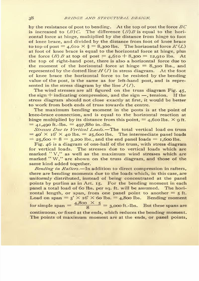
38 BRIDGE AND STRUCTURAL DESIGN.
by the resistance of post to bending-. At the top of post the force BCis increased to (J3)C. The difference (B)B is equal to the hori-
zontal force athinge, multiplied by
the distance fromhinge
to foot
of knee brace, and divided by the distance from foot of knee brace
to top of post=
4,610 X - =8,300 Ibs. The horizontal force K(L)
at foot of knee brace is equal to the horizontal force at hinge, plus
the force (B) B at top of post=
4,610 + 8,300=
12,910 Ibs. At
the top of right-hand post, there is also a horizontal force due to
the moment of the horizontal force at hinge=
8,300 Ibs., and
represented by the dotted line- .//(/) in stress diagram. At the foot
of knee brace the horizontal force to be resisted by the bendingvalue of the post, is the same as for left-hand post, and is repre-
sented in the stress diagram by the line J(f).
The wind stresses are all figured on the truss diagram Fig. 45,
the sign+ indicating compression, and the sign ,tension. If the
stress diagram should not close exactly at first, it would be better
to work from both ends of truss towards the centre.
The maximum bending moment in the posts is at the point of
knee-brace connection, and is equal to the horizontal reaction at
hinge multiplied by its distance from this point,=
4,610 Ibs. X 9 ft.
=41,490 ft.-Ibs. = 497,880 in.-Ibs.
Stresses Due to Vertical Loads. The total vertical load on truss
=40' X 16' X 40 Ibs. = 25,600 Ibs. The intermediate panel loads
=25,600 -5- 8 = 3,200 Ibs., and the end panel loads = i,600 Ibs.
Fig. 46 is a diagram of one-half of the truss, with stress diagram
for vertical loads. The stresses due to vertical loads which are
marked "V," as well as the maximum wind stresses which are
marked"W," are shown on the truss diagram, and those of the
same kind added together.
Bending in Rafters. In addition to direct compression in rafters,
there are bending moments due to the loads which, in this case, are
uniformly distributed, instead of being concentrated at the panel
points by purlins as in Art. 15. For the bending moment in each
panel a total load of 60 Ibs. per sq. ft. will be assumed. The hori-
zontal length, or span, from one panel point to another = 5 ft.
Load on span 5' X 16' X 60 Ibs. = 4,800 Ibs. Bending moment
for simple span= -
g=
3,000 ft.-lbs. But these spans are
continuous, or fixed at the ends, which reduces the bending moment.
The points of maximum moment are at the ends, or panel points,

7/30/2019 Bridge Structural 00 Thom Rich
http://slidepdf.com/reader/full/bridge-structural-00-thom-rich 49/104
DESIGN OF A KNEE-BRACED BUILDING. 39
and the moment at these points is equal to two-thirds of the bend-
ing1 moment for a span of the same length but not fixed at the ends,
3,000 X YZ = 2,000 ft.-lbs. = 24,000 in.-lbs.
Proportioning of Members. For the rafters angles must be selected
of such section that the maximum stress per sq. in., due to the
combination of direct compression and bending, shall not exceed
12,000 Ibs. 2 5' X 3 X TV angles will be assumed with the
longer legs vertical. Area = 4.8 sq. ins. R =3.78. Then
Max. compression -f- area = 36,900 -f- 4.8 =7,690
Max. bending -f- R = 24,000 -*- 3.78 = 6,350
14,040 Ibs. per sq. in.
Since the total fibre stress as above is too great, 2 5 X 3 X
Y%, Ls will be tried next. Area = 5.72 sq. ins. R = 4.42, then
36,900 -*- 5.72=
6,450
24,000 -5- 4.42=
5,430
1 1,880 Ibs. per sq. in.
This is satisfactory, and the same angles will be used throughout
the rafters to avoid splicing.
In members de and fg there is a compression stress of 4,650 Ibs.,
and their length is about 3.3 ft. Assuming I 2^ X 2 X ^ L1 3,3= 1.06 sq. ins. least r .43". Then = ~~ =
7.6,which by table
(Art. 12)corresponds
to
8,210Ibs.
per sq.in. for
pin ends,and
4,650 -v- 8,210 = .56 sq. ins. required. The area provided is nearly
double this amount.
In members elf
lthe compression
=13,100 Ibs., length
= 6.6 ft.
2 2/^2 X 2>2 X ^ angles will be assumed, area ==2.38 sq. ins.
least r .77,= ~ =
8.7, corresponding to 7,470 Ibs. per sq.
in. Then 13,100 -*-7,470 1.75 sq. ins. required.
Membersee
l
willbe made
of thesame
section as^/,.
The knee braces must be designed for 10,700 Ibs. or + 1,6000
Ibs. Assuming 2 3 X 2,^/2,X % angles with the longer legs back
to back, area = 2.62 sq. ins. least r .95. / = 8.3.= ~^
8.7, corresponding to a unit stress of 7,470 Ibs. Then 1,6000 +
7,470=
2.14 sq. ins. required.

7/30/2019 Bridge Structural 00 Thom Rich
http://slidepdf.com/reader/full/bridge-structural-00-thom-rich 50/104
40 BRIDGE AND STRUCTURAL DESIGN.
The sections required and those provided for the tension members
are all figured on diagram Fig. 46.
The posts must be designed for bending stresses as well as direct
compression. A 12 in. I @ 31.5 Ibs. is assumed. Area = 9.26 sq,
ins. R =36, then
Direct compression -f- area = 20,800 Ibs. -s- 9.26=
2,250
Bending moment -*- R = 497,880 in. -Ibs. -5- 36 =13,830
16,080 Ibs. persq. in.

7/30/2019 Bridge Structural 00 Thom Rich
http://slidepdf.com/reader/full/bridge-structural-00-thom-rich 51/104
DESIGN OF A KNEE-BRACED BUILDfNG. 41
The maximum compression as above is greater than that allowed
for the other members, but since it is nearly all due to bending from
a maximum wind force which the building will rarely, if ever,
receive, and as the posts are supported sidewise by the planking,
this unit stress is not at all excessive.
Anchorage for Posts. The value of one anchor bolt has been
taken at
7,800Ibs., and it must be let down into the foundation far
enough to develop an equal resistance. 100 Ibs. per sq. in. is a
safe value for the adhesion of cement mortar to iron, and, as the
circumference of a one-inch bolt is about 3 inches, the adhesion
per lineal inch will be 300 Ibs. Then 7,800-*- 300
= 26 inches =
length of bolt required in foundation. It would be better to extend
bolts into foundation somewhat deeper than this, say 36 inches.

7/30/2019 Bridge Structural 00 Thom Rich
http://slidepdf.com/reader/full/bridge-structural-00-thom-rich 52/104
42 BRIDGE AND STRUCTURAL DESIGN.
The width of foundation wall is assumed to be 24 inches, and its
depth 5 ft. In constructing- the wall, a break about 24 inches wide
should be made at each post. The anchor bolts should then be set
in their proper position by means of a template, and the space filled
with Portland cement concrete.
The anchor bolt in resisting the bending- moment at base of post
tends to overturn the wall with a moment equal to the value of one
bolt, multiplied by its distance from the further edge of base plate
=7,800 Ibs. X 18 ins. = 140,400 in.-lbs. This overturning mo-
ment is resisted, partly by the weight of the wall, and partly by the
earth filling- around it. The resistance of the wall is easily figured,
but that of the earth filling- is very indefinite and uncertain, so the
latter will be neglected in the present case. The weight of wall
required is equal to the overturning moment divided by the dis-
tance from centre of wall to its edge,=
140,400 in.-lbs. -=- 12 ins. =
11,700 Ibs. Taking the weight of masonry at 150 Ibs. per cu. ft.
the weight of a section of wall one foot long=
5'X 2' X 150 Ibs.
=1,500 Ibs., then 11,700 -*- 1,500
=7.8 ft., which is the length of
wall required to resist the overturning moment due to anchor bolts.
As the posts are 16 ft. apart, it is evident that the wall has ample
stability in itself without the assistance of the earth filling.
Fig. 47 is a detail drawing showing one-half of truss and one
post. The general method of designing details as explained in
Art. 15 also applies to the present example.
ART. 18. THE DESIGN OF A PLATE GIRDER.
Data : Length, centre to centre of bearings, 50 ft.
Depth, back to back of angles, 5 ft.
Load, 4,000 Ibs. per lineal foot.
Tension, 15,000 Ibs. per square inch.
Shearing, 7,500 Ibs. per square inch for web plates.
Shearing, 10,000" " " " "
rivets.
Bearing, 20,000" "
Size of rivets f-in.
The bending moment at the centre is given by the formula,
w I2
4,000 x 502
M = = =i,250,000 ft.-lbs.
8 8
The flange stress at the centre equals the moment divided by the
depth, centre to centre, of gravity of flanges. When the flanges

7/30/2019 Bridge Structural 00 Thom Rich
http://slidepdf.com/reader/full/bridge-structural-00-thom-rich 53/104
THE DESIGN OF A PLA TE GIRDER. 43
have cover plates the centre of gravity is usually near the back of
the angles, and sometimes beyond that point, but it is customary
to assume the effective depth of such a girder as the distance backto back of angles. As the present example will undoubtedly have
cover plates, the effective depth will be 5 ft. Then, the flange stress
at centre = 1,250,000 -f- 5=
250,000 Ibs. and the net area required
in bottom flange=
250,000 -f- 15,000=
16.67 square inches. When
practicable, the area of the angles should be equal to at least one-
third of the total flange area.
The following section will suit the case :
Gross Area. Eivet Holes. Net Area.
Two6X3/^X/^ Ls= 9.00 (4X y% X /^=
1.75)
Two isXA- plates=n.38 (4X^X^=1.52)
20.38 17.11
Allowance has been made for two holes in each angle, for, al-
though the holes may not come exactly opposite each other, their
stagger will not be great enough to make it allowable to deduct the
area of only one hole. When rivets are staggered three inches or
more only one hole need be allowed for.
Having decided on the section of the bottom flange, it is cus-
tomary to make the top flange the same, except in rare cases when
the top flange is unsupported laterally. It may then be necessary to
make the top flange wider, and to figure it as a column. In the pres-
ent example, the top flange is supposed to be supported laterally at
intervals not exceeding fifteen times its width.
Length of cover plates. In Art. 5 it was seen that the bending
moment at any point of a beam supported at both ends and loaded
uniformly was represented by ordinates between a parabola, whose
vertex was at the centre, and the closing line connecting the points
of intersection of the parabola with verticals through the points of
support of beam. Now the flange stress at any point; also the re-
quired flange area may be represented in the same manner.
Figure 50 represents one half of the girder, which is divided into
equal panels of 5 ft. In Fig. 50^ a parabola is constructed with a
base AB equal to one-half the span of girder, and height BC equal
to the area required at centre. To construct the parabola, the line
AD BC 16.67a"
is divided into the same number of equal parts
as the line AB, and from the points of division lines are drawn

7/30/2019 Bridge Structural 00 Thom Rich
http://slidepdf.com/reader/full/bridge-structural-00-thom-rich 54/104
44 BRIDGE AND STRUCTURAL DESIGN.
SQ.Q cenltc To cgntu of bearing^
Fig.SI
4-rF/g.
52

7/30/2019 Bridge Structural 00 Thom Rich
http://slidepdf.com/reader/full/bridge-structural-00-thom-rich 55/104
THE DESIGN OF A PLATE GIRDER, 45
to the point C, as shown. The intersections of these radial lines with
the verticals through the points of division of the lineAB are points
on the parabola. On this parabola are plotted the areas of the
angles and cover plates. The angles extend the full length of the
girder. The first cover plate is required to the point E, but it is
customary to extend it about one foot beyond this point, which
will make the length of the plate 40 ft. The second cover plate is
required to the point F. Adding one foot at each end will make
the length of this plate 28 ft.
The following analytical method for determining the proper
length of cover plates will give the same results as the above graph-
ical method;but the graphical method is preferable on account of
its simplicity, and because with it there is much less chance of
errors.
In Fig. 51, A = area required at centre of span.
A! = area required at end of ist cover plate.
A2= area required at end of 2d cover plate.
X = distance from centre' of span to theoretical end
of ist cover plate.
X2= distance from centre of span to theoretical end
of 2d cover plate.
1 = length of span, centre to centre of bearings.
ThenX^A
AIn the present example A= 16.67 ", A t =7.25 ", A 2= 7.25+4.93
= 12.18 a",=
25 ft.
-V(16.67 7.25) X25
2
-= 18.8 ft. Total length of ist
16.67
plate= (i8.8'X 2) + 2' = 39.6 ft., say 40 ft.
(16.67 i2.i8)X25
s
X 2 = = 12.9 ft. Total length of 2nd plate =16.67
(12.9X2) +2'= 27.8 ft., say 28 ft.
The web plate must have a sectional area great enough to resist
the shear, and it must be thick enough to give sufficient bearing for
the rivets in flange angles and end stiffeners.
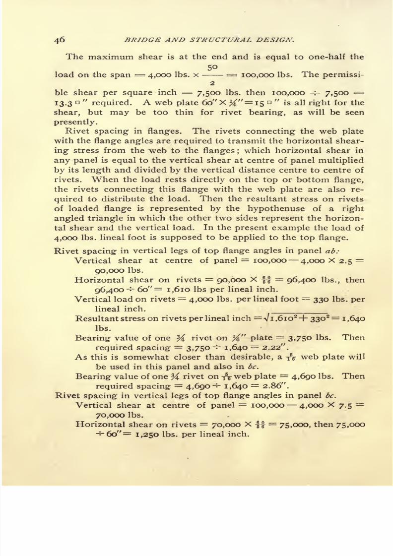
7/30/2019 Bridge Structural 00 Thom Rich
http://slidepdf.com/reader/full/bridge-structural-00-thom-rich 56/104
46 BRIDGE AND STRUCTURAL DESIGN.
The maximum shear is at the end and is equal to one-half the
50
load on the span = 4,000 Ibs. x = 100,000 Ibs. The permissi-2
ble shear per square inch = 7,500 Ibs. then 100,000 -r- 7,500=
13.3a"
required. A web plate 60" X #"= 15"
is all right for the
shear, but may be too thin for rivet bearing, as will be seen
presently.
Rivet spacing in flanges. The rivets connecting the web plate
with the flange angles are required to transmit the horizontal shear-
ing stress from the web to the flanges ;
which horizontal shear in
any panel is equal to the vertical shear at centre of panel multiplied
by its length and divided by the vertical distance centre to centre of
rivets. When the load rests directly on the top or bottom flange,
the rivets connecting this flange with the web plate are also re-
quired to distribute the load. Then the resultant stress on rivets
of loaded flange is represented by the hypothenuse of a right
angled triangle in which the other two sides represent the horizon-
tal shear and the vertical load. In the present example the load of
4,000 Ibs. lineal foot is supposed to be applied to the top flange.
Rivet spacing in vertical legs of top flange angles in panel ad:
Vertical shear at centre of panel= 100,000 4,000 X 2.5
=
90,000 Ibs.
Horizontal shear on rivets = 90,000 X -f-f=
96,400 Ibs., then
96,400-:- 60"= 1,610 Ibs per lineal inch.
Vertical load on rivets = 4,000 Ibs. per lineal foot = 330 Ibs. per
lineal inch.
Resultant stress on rivets per lineal inch = Vi ,6io2+ 33O
2=i ,640
Ibs.
Bearing value of one Y\ rivet on %" plate=
3,750 Ibs. Then
required spacing=
3,750-^- 1,640= 2.22".
As this is somewhat closer than desirable, a yV web plate will
be used in this panel and also in be.
Bearing value of one
^rivet on
&web plate
=4,690 Ibs. Then
required spacing = 4,690-^ 1,640 = 2.86".
Rivet spacing in vertical legs of top flange angles in panel be.
Vertical shear at centre of panel=
100,000 4,000 X 7.5=
70,000 Ibs.
Horizontal shear on rivets = 70,000 X =75,000, then 75,000
-s-6o"= 1,250 Ibs. per lineal inch.

7/30/2019 Bridge Structural 00 Thom Rich
http://slidepdf.com/reader/full/bridge-structural-00-thom-rich 57/104
THE DESIGN OF A PLATE GIRDER. 47
Resultant stress on rivets per lineal inch = y 1,250*+ 330*=
1290
Ibs.
Required spacing- of rivets in -f^" web plate = 4,690^- 1,290 =3.65".
Rivet spacing in vertical legs of top flange angles in panel cd.
Vertical shear at centre of panel=
100,000 4,000 X 12.5=
50,000 Ibs.
Horizontal shear on rivets = 50,000 X g=
53,600, then 53,600
-* 60"= 895 Ibs. per lineal inch.
Resultant stress on rivets per lineal inch=V8952
+33O2=950 Ibs.
Required spacing of rivets in %" web plate = 3,750^-950 =3.94".
Rivet spacing1
in vertical legs of top flange angles in panel de.
Vertical shear at centre of panel=
ioo,ooc 4,000 X 17.5=
30,000 Ibs.
Horizontal shear on rivets = 30,000 X ff = 32,500 Ibs., then
32,500 -f- 60"= 540 Ibs. per lineal inch.
Resultant stress on rivets per lineal inch= V54O2
-f-33O2= 620 Ibs.
Required spacing: of rivets in %" web plate=3,750-^- 620=6.05' .
It is unnecessary to proceed further as the maximum spacing
should not exceed 6".
Rivets in flange plates. The ist flange plate requires a
sufficient number of rivets between its end and the end of
the 2d flange plate to transmit to it its full proportion of the
flange stress. The distance from the end of the ist plate to the
end of the 2d plate is 6 ft. = 72 inches. The net area of the plate
= 4.93 square inches;then 4.93 x 15,000 = 73,950 Ibs., = its pro-
portion of the flange stress. The value of one f rivet in single
shear = 4,420 Ibs. Then 73,950-~-
4,420 = 16 rivets required in
72". Since there are two lines of rivets in the plate, the required
longitudinal spacing=
72" -^ 8 = 9". But the pitch should not
exceed 16 times the thickness of the plate, nor should it be more
than 6". The 2d flange plate requires the same number of rivets
between its end and the centre of the span= 14 ft.
The rivet spacing on top and bottom flanges will be made alike
and as uniform as possible in order to simplify the template work.
In the vertical legs of angles the spacing will be 2/4" iroma to b, 3"
from b to d and 6" from d to /. In the flange plates the spacing will
be 6" throughout, except at splice, and the rivets will be staggered
with those in the vertical legs of flange angles.

7/30/2019 Bridge Structural 00 Thom Rich
http://slidepdf.com/reader/full/bridge-structural-00-thom-rich 58/104
48 BRIDGE AND STRUCTURAL DESIGN.
Web splices. A 60 X y5
^ web plate will be used from a to c, and
a 60 X ^ web plate from c to /. The plates will be spliced at c and /.
Web splice at c. The shear at this point= 60,000 Ibs. The rivets,
although in double shear, have bearing on one side of the splice of
only J". The value of one f rivet, bearing on J" plate=
3,750 Ibs.
Then, the number of rivets required side of splice adjacent to \n
web plate= 60,000
-=-3,750
= 16. Two 12"xJ" splice plates will be
used, and the rivets staggered as shown in detail, Fig. 53. The same
number of rivets are used on side of splice adjacent to 5/16
" web
plate for symmetry and to simplify the template work.
Web splice at /. There is no shear at this point. Two 6" x J"
splice plates will be used with a single line of rivets about 6" apart,
each side of joint.
End Stiffeners. The duty of the end stiffeners is to transfer the
shear from the web plate to the abutments. They act as columns,
but as the ratio of their length to their radius of gyration is small,
the unit stress of 12,000 Ibs. per square inch may be used without
reduction by formula. The end shear or reaction = 100,000 Ibs.,
then 100,000 -r- 12,000 = 8.33 square inches required in end stiffen-
ers. Four 5 x 3 x 5/16 Ls= 9.60 square inches will be used, placed
as shown in Fig. 52, which arrangement is best suited to distribute
the load over the bearing plate. The rivets are in bearing on 5/16
plate, then the value of one f rivet = 4,690 Ibs., and the number of
rivets required = 100,000 -f- 4,690=
21, or n rivets in each pair
of angles. Between the end stiffeners and the web plate 3" x J"
fillers will be used to avoid offsetting the angles, and thus obtain a
better fit. These stiffeners and fillers should fit against the bottom
flange angles perfectly.
Intermediate Stiffeners. In case of a heavy concentrated load at
any point of the girder, stiffeners should be proportioned in the
same manner as the end stiffeners to carry this load and distribute
it into the web plate ; otherwise, the intermediate stiffeners are sim-
ply to prevent the web from buckling, and are usually spaced about
as far apart as the depth of girder. There is no scientific method of
proportioning them, and no generally accepted rule. In the pres-
ent case two 3 x 3 x \ Ls will be used. At the top and bottom they
will be offset, or crimped, to fit over the flange angles.
Bearing Plates. If the girder rest on a solid stone at each end,
the bearing pressure may be 300 Ibs. per square inch, but if it be
supported on brickwork, the bearing pressure should not exceed

7/30/2019 Bridge Structural 00 Thom Rich
http://slidepdf.com/reader/full/bridge-structural-00-thom-rich 59/104
THE DESIGN OF A PLA TE GIRDER. 49

7/30/2019 Bridge Structural 00 Thom Rich
http://slidepdf.com/reader/full/bridge-structural-00-thom-rich 60/104
50 BRIDGE AND STRUCTURAL DESIGN.
ioo Ibs. per square inch. In the present case, the former condition
will be assumed;then the required area of bearing plate
= 100,000
-f- 300= 333 square inches. A 16" x f x 21" plate will be used ; its
area = 336 square inches.
Flange Splice. Angles and flange plates may be obtained up to
sixty or seventy feet or even longer ; but, if the girder is to be made
from stock lengths, it may be necessary to splice the angles and the
first cover plate. For the purpose of illustration, these will be spliced
near the centre of the span as shown in Fig. 53. The net area of
plate=
4.93 square inches, then 4.93 x 15,000=
73,950 Ibs. =value of plate. The single shearing value of one f rivet = 4,420 Ibs.
then 73,950-~-
4,420 = 17 rivets required on each side of splice.
The drawing shows 18 rivets. The net area of the angles=
7.25
square inches, then 7.25 X 15,000=
108,750 Ibs. = value of angles,
and 108,750 -f- 4,420=
25 rivets required. The drawing shows
18 rivets in the 6" legs of angles, and 4 rivets in the 3^" legs, which
latter are in double shear and may be counted as 8 rivets. The
total number of rivets in angle splice is then 18 + 8 = 26. It
should be noted that there are about twice as many rivets
in the 6" legs as in the 3^" legs. The splice plates should
have at least as much section as the pieces spliced. A 13 x J plate
is used; its net area, making allowance for two J holes = 5.62
square inches. In addition to this, the vertical legs of the angles
are covered by two 3 x 9/16 flats of net area = 2.39 square inches.
Then 5.62 + 2.39= 8.01 square inches in splice material for
angles, which is somewhat greater than the net area of the angles.
A common error is to put a long string of rivets in a narrow splice
plate, but it will readily be understood that it is useless to use more
rivets in a splice plate than are required to develop its full strength.
Here, the two 3 x 9/16 flats = 2.39 square inches net area,
and 2.39 x 15,000 Ibs. = 38,500 Ibs. In these flats are 4 rivets
in full double shear which are equivalent to 8 rivets in single shear,
then 4,420 x 8 = 35,360 Ibs. = value of rivets in splice plates.
ABT. 19. PLATE GIBDEB WITH ONE-EIGHTH OF WEB PLATE COMPUTEDAS FLANGE ABEA.
In the foregoing example, Art. 18, it has been assumed that the
bending- moment is resisted entirely by the flanges, and that the
web plate takes shear only. This is not strictly correct, but is in
conformity with many specifications. It seems to be better prac-

7/30/2019 Bridge Structural 00 Thom Rich
http://slidepdf.com/reader/full/bridge-structural-00-thom-rich 61/104
ONE-EIGHTH OF WEB PLATE AS FLANGE. AREA. 51
tice, however, to make due allowance for the resistance of the web
plate in designing the flanges.
The moment of resistance of web plate = -g- = -7- h = ~T h.
In which b = thickness of web plate.
h =height
" "
A"= area
Making allowance for a vertical line of one-inch holes, 4-inch
Awcentres, the net moment of resistance of web plate
=-g-
h.
The moment of resistance of the flanges = Afh.
In which A* = area of one flange.
h = depth of girder centre to centre of gravity of flanges,
and assumed to be equal to the height of web
plate when flange plates are used.
Then, total moment of resistance of girder=
(fh) + (
A'h)
=( + A')
h.
Therefore, one-eighth of the area of web plate may be computed
as flange area. The following is an alternative design for the
girder, using the same shears and moments as before. A -%" web
plate will be used throughout.
Flange area required at centre = 16.67 sq. ins.
Flange material provided=
yi
of
59# x Aweb
Plate = 2
-3
2
2 6 X Zl
/2 X T7* Ls = 7-94 gross (less 4, # holes) = 6.41
2 13 X H plates=
9.76 gross (less 4, # holes)=
8.44
17.17 sq. ins. net.
The first cover plate requires to be 37 ft. long, and the second
cover plate 26 ft. long.
Rivet spacing in vertical legs of flange angles.
The longitudinal shear per lineal inch, at any point on the rivet
line, is equal to the vertical shear at the point, divided by the
distance, in inches, centre to centre of the rivets in the vertical legs
of the top and bottom flange angles ; and the amount of this shear
to be transferred by the rivets to the flanges is proportioned to
Area of one flange at the point.
Area of one flange + }i of web plate.

7/30/2019 Bridge Structural 00 Thom Rich
http://slidepdf.com/reader/full/bridge-structural-00-thom-rich 62/104
BRIDGE AND STRUCTURAL DESIGN.
Rivet spacing in panel a b.
Shear at centre of panel=
90,000 Ibs.
Distance centre to centre of rivets in verticallegs
oftop
and
bottom flange angles = 56 inches.
Net area of one flange at this point=
6.41
J/b of 59 >^ X TV web plate=
2.32
6.73 sq. ins.
Vertical load on rivets = 330 Ibs. per lineal inch.
Bearing value of one ^ rivet on -fy plate=
4,690 Ibs.
90,000
Then, longitudinal shear per lineal inch at rivet line =
longitudinal shear per lineal inch on rivets = 1,610 X ^~J^
resultant stress on rivets per lineal inch =
= 1,610 Ibs.
= i.iSolbs.
-f-3308 = 1,220 Ibs.
6.41
required spacing of rivets in top flange inches.
The required rivet spacing in the remaining panels is found simi-
larly. The required rivet spacing in flange plates is determined as
before.
Web Splices. Since one-eighth of the web plate has been com-
puted as flange area, the splices must be capable of resisting the
full amount of bending moment attributed to the web, as well as
the vertical shear at the point.
Bending value of web plate=
2.32 sq. ins. X 15,000 Ibs. X 60
ins. =2,088,000
in.-lbs.
The moment of resistance of
the splice must be equal to or
greater than that of the web.
Horizontal splice plates 8
inches wide will be used adjacent
to the flange angles, and vertical
splice plates, 12 inches wide be-
tween them, as shown in Fig. 54.The number and spacing of the rivets will first be assumed, and
then their value investigated.
The maximum bearing value of one ^ rivet on -$ web = 4,690
Ibs., but its value in resisting bending moment when located in
neutral axis of girder is zero.
Fig. 64.

7/30/2019 Bridge Structural 00 Thom Rich
http://slidepdf.com/reader/full/bridge-structural-00-thom-rich 63/104
ONE-EIGHTH OF WEB PLATE AS FLANGE, AREA. 53
The distance from neutral axis to top or bottom of girder=
30
inches. Then the value of one rivet, one inch from neutral axis =
A f~\C\C\'
156 Ibs. The value of any rivet will be equal to 156 Ibs.,
multiplied by its distance from the neutral axis, and its moment of
resistance will be equal to 156 Ibs., multiplied by the square of this
distance. Then taking- all the rivets in splice plates on one side of
the joint, both above and below the neutral axis, their moment of
resistance is as follows :
4 rivets X 156

7/30/2019 Bridge Structural 00 Thom Rich
http://slidepdf.com/reader/full/bridge-structural-00-thom-rich 64/104
54 BRIDGE AND STRUCTURAL DESIGN.
ART. 20. DESIGN FOR A WARREN GIRDER HIGHWAY BRIDGE.
(Figs. 55 and 56.)
Data:Length,
centre to centre, of
bearings, 50'
o".
4 panelsof
12' 6".
Depth, centre to centre of chords, 6' o".
Roadway 16' o" clear. Width, centre to centre of trusses,
17' o".
Dead load (wooden stringers and floor planking) . . . 250
Dead load (steel) 150
Total (pounds per lineal foot) 400
Live load, 80 Ibs. per square foot of roadway. Then 80
Ibs. x 16'= 1,280 Ibs. per lineal foot.
Tension, 15,000 Ibs. per square inch.
Compression, 1,200 Ibs. per square inch, reduced by Ran-
kine's formula. Top chords to be considered as columns
with square ends, and web members as columns with pin
ends. No compression member shall have a length ex-
ceeding
120 times its least radius of
gyration.Rivet shearing, 7,500 Ibs. per square inch.
Rivet bearing, 15,000 Ibs. per square inch.
In determining the dead load, as above, the floor is supposed to
consist of 3" plank, laid- on 3 x 12 joists about 2' centres, and esti-
mated to weigh 3 Ibs. per foot (board measure). The weight of steel
per lineal foot is given by the formula 2 x L + 50 in which L=length of span in feet. Then (2 x 50') + 50
=150 Ibs. per lineal foot.
400The dead load per panel for one truss = Xi2.s'= 2,500 Ibs.
2
1,280The live load per panel for one truss = X 12.5'= 8,000 Ibs.
2
These loads are supposed to be concentrated at the lower panel
points, c, e and g.
The length of the diagonal members = V6*+6.252 =
8.6/.
The stress in any diagonal is equal to the shear in the panel in
which it is situated, multiplied by the length of diagonal and divided
by depth of truss;and the shear in any panel is equal to the end
reaction, minus any loads between this end and the panel considered.
The stress in any chord section is equal to the bending- moment
at the point where the diagonals in the panel intersect the opposite
chord, divided by the depth of truss.

7/30/2019 Bridge Structural 00 Thom Rich
http://slidepdf.com/reader/full/bridge-structural-00-thom-rich 65/104
WARREN GIRDER HIGHWA Y BRIDGE. 55
The dead load stresses will be considered first.
The reaction at either end is equal to one-half the load on span,
or one and one-half panel loads, =2,500X 1/^= 3,750 Ibs.
The shear in panel ac is equal to the reaction at a, and the stresses
in members aB and Be which lie in this panel will be equal but of
opposite kind. Thus aB will be in compression and Be in tension.
The shear in panel ce is equal to the reaction at,minus the load
at ctand the stresses in cD and De are also equal but opposite.
For the stress in ac moments are taken about the point B, which
is distant 6.25' horizontally from a. The moment at this point is
equal to the reaction at a multiplied by its distance from B.
For the stress in ce moments are taken about the point D, which
is distant 18.75' horizontally from a. The moment is equal to the
reaction at a, multiplied by its distance from Dtminus the load at
c, multiplied by its horizontal distance from D.
For the stress in BD moments are taken about the point c, dis-
tant 12.5' from a, and the moment is equal to the reaction at a,
multiplied by this distance.
For the stress in DF moments are taken about the point e, dis-
tant 25' from a. The moment at this point is equal to the reaction
at a multiplied by its distance from e, less the load at c multiplied
by its distance from e.
With the above explanation the following: table of stresses will
readily be understood :
DEAD LOAD STRESSES.
Shear in panel 0^=3750 o=
3750* "
^=3750 2500 = 1250
Moment at B =375X 6.25' =23427
.75'
^=3750x12.5' =46875
e=3750X25.0'
2500X I2.5'=62400
8.67Stress in aB Bc= 375OX =6 5420
8.67" " cD De= I250X = 18106
" " ac =23437X i=
39io" " ce =54687X
" = 9110
BD =46875X" = 7810
" DF =624oox"
=10400
The diagonals in the end panels as well as the top and bottom
chords throughout, will receive their maximum live load stresses
when the bridge is fully loaded;but the maximum stresses in the
intermediate diagonals is caused by unsymmetrical loading; thus
cD will receive its greatest compression, and De its greatest tension
with live loads at e and g only ;while eF will receive its greatest
compression, and Fg its greatest tension with live load at g only.
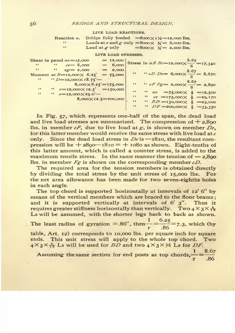
7/30/2019 Bridge Structural 00 Thom Rich
http://slidepdf.com/reader/full/bridge-structural-00-thom-rich 66/104
56 BRIDGE AND STRUCTURAL DESIGN.
LIVE LOAD REACTIONS.
Reaction a. Bridge fully loaded =8000Xi>=12,000 Ibs.
" Loads at e and^ only =8000X
%=6,000 Ibs.
" Load at g- only =8oooX /= 2,000 Ibs.
LIVE LOAD STRESSES.
8,ooox 12. 5=200,000
8.67hear in panel a<r=i2,ooo = 12,000
" " ce= 6,000 = 6,000
" "eg= 2,000 = 2,000
Moment at j9=i2,oooX 6.25'=
75,000"Z>=i2,ooox 18. 75'
8,ooox6.25'=i75,ooo" " eF Fg= 2,ooox '=
2,890"
tr=i2,oooXi2-5' =150,000" ",=12,000x25.0'-
[
ac =75 JoooX i =12,500
Stress in a c=i2,ooox =17,3406
" cD De= 6,ooox7=
8,6706
i75,ooox i =29,170
=25,000
200,000X i =33>33o
In Fig. 57, which represents one-half of the span, the dead load
and live load stresses are summarized. The compression of + 2,890
Ibs. in member eF, due to live load at g, is shown on member De>
for this latter member would receive the same stress with live load at c
only. Since the dead load stress in De is 1810, the resultant com-
pression will be + 2890 1810 = + 1080 as shown. Eight-tenths of
this latter amount, which is called a counter stress, is added to the
maximum tensile stress. In the same manner the tension of 2,890
Ibs. in member Fg is shown on the corresponding- member cD.
The required area for the tension members is obtained directly
by dividing the total stress by the unit stress of 15,000 Ibs. For
the net area allowance has been made for two seven-eighths holes
in each angle.
The top chord is supported horizontally at intervals of 12' 6" by
means of the vertical members which are braced to the floor beams;
and it is supported vertically at intervals of 6' 3". Thus it
requires greater stiffness horizontally than vertically. Two 4 X 3 X -ft-
Ls will be assumed, with the shorter legs back to back as shown.
1 6.25The least radius of gyration =.86", then = =
7.3, which (by
r .86
table, Art. 12) corresponds to 10,000 Ibs. per square inch for square
ends. This unit stress will apply to the whole top chord. Two
4X 3 X T8- Ls will be used for BD and two 4X3X ^ Ls for DF.
\ 8.67
Assuming the same section for end posts as top chords,=
r .86

7/30/2019 Bridge Structural 00 Thom Rich
http://slidepdf.com/reader/full/bridge-structural-00-thom-rich 67/104
WARREN GIRDER HIGHWAY BRIDGE.
=10.1, which corresponds to a unit stress of 6,600 Ibs. per square
inch for pin ends. Two 4X3X^1? Ls will be used. For member
cD two 3X2^XX Ls are assumed, with the 3" legs back to back.
1 8.67=--=9.1, then allowable unit stress =7,300 Ibs. It will be
r -95
Fig.55
12-6
-So'-o c.1o c.1 endbearings
-
Fig. 51
16.o
-t7'.oe.toC..
Fig.5 8
found that the area of two 3X2^=^ Ls is considerably greater
than required for the stress, but if smaller angles were used the
length would exceed 120 times the least radius of gyration.
For member De the same section will be used, as this is also a

7/30/2019 Bridge Structural 00 Thom Rich
http://slidepdf.com/reader/full/bridge-structural-00-thom-rich 68/104
58 BRIDGE AND STRUCTURAL DESIGN.
compression member under certain conditions of loading, as
explained on page 56.
The verticals Cc Ee have no direct stress ; their duty is to stiffen the
top chord. For these members two 2^2X2% X % Ls will be used.
Floor Beams, Fig. 58. The dead load consists of the floor,
which was assumed to weigh 250 Ibs. per linl. ft., plus the weight
of the beam itself. Then
Dead load = 25oX i2.5'-|-5oo= 3,625
Live load =1,280X12.5' =16,000
Total, 19,625 Ibs.
The load extends over sixteen feet of the floor beam, which is the
width of roadway ;but the effective length for computing the
moment is the distance centre to centre of trusses=i7 ft. The re-
19,625action at each end = . The moment at the centre is equal to
2
the reaction multiplied by one-half the span, less the portion of the
load on one side of the centre, multiplied by the distance to its
centre of gravity.
^19,625 \ 719,625 \ 19,625Floor beam moment=(-^
-Xg.s') (-^ ?X 4')=- -X
2 228.5 4) =44, 1 50 foot-lbs.
44,150 foot-lbs. X 12=529,800 inch-lbs. Then 529 ,800-^-1 5,000=
35.3= R required.
A 12" I @ 31.5 Ibs. will be used. Its R=36.Laterals. The lateral system, Fig. 56, is a horizontal truss of
50 ft. span, and 17 ft. deep. There are 4 panels of 12' 6" each.
Length of diagonals=
V 12.5* + I72 = 21.1'. The wind pressure
is taken at 300 Ibs. per lineal foot of bridge, then a panel load =300 x 12.5
=3,750 Ibs. As in the vertical trusses, there is a panel
load at each point c, e, and g, and half panel loads at a and',which
latter do not affect the stresses. The reactions as well as the shear
in the end panel = 3,750 x i = 5,620 Ibs. The stress in the end
21. 1
diagonals = 5,620 x = 6,790 Ibs., and 6,790 -r- 15,000 = .46
17
square inches required. One 2\ x 2 x J L will be used. Its net area,
allowing for one J" hole = .84 square inches. The same section will
also be used for the next diagonal.
Details, Fig. 59. Taking the shearing value of rivets at 7,500 Ibs.

7/30/2019 Bridge Structural 00 Thom Rich
http://slidepdf.com/reader/full/bridge-structural-00-thom-rich 69/104
WARREN GIRDER HIGHWAY BRIDGE. 59

7/30/2019 Bridge Structural 00 Thom Rich
http://slidepdf.com/reader/full/bridge-structural-00-thom-rich 70/104
60 BRIDGE AND STRUCTURAL DESIGN.
per square inch, and the bearing value at 15,000 Ibs. per square inch,
the value of one f"
rivet in single shear= 3,310 Ibs., bearing on f"
plate= 4,220Ibs. and
bearingon
J" plate= 2,810Ibs.
The num-ber of rivets required are clearly shown on the drawing, and it is
only necessary to explain one or two points.
The bearing- plate at a requires to be large enough so that the
pressure on the masonry shall not exceed 300 Ibs. per square inch.
The dead load reaction = 3,750 Ibs. and the live load reaction
= 12,000 Ibs., making a total of 15,750 Ibs. Then, 15,750-=-
300 =50 square inches required. The plate used, which is 12" x i6J"
=
198 square inches, is much larger than necessary for bearing onthe masonry. It also requires to be large enough for the anchor
bolt and to make connections with the bottom chord angle and the
laterals. At B the hip cover plate is added to give more lateral
stiffness at this point. The bottom chord splice at c is formed partly
with the gusset plate, and partly with the plate on the bottom. The
net area through the splice should not be less than that required
in the member a c, viz., 1.09 square inches. It is evident that the
whole width of the gusset plate cannot be relied on, as the pull is all
on one edge, and if the plate were to begin to fail at the edge, a
piece of it would soon be torn off. It is only safe to figure on a
width of plate equal to twice the rivet gauge in the angle,= 2j",
and from this width should be deducted the diameter of the rivet
hole, J". Then the net area = (2.75" .875') x f" =
.70 square
inches. The net area of the bottom plate making allowance for
two 7/s" holes = (7.5
~1-75) X # =
1.44 square inches. Then
the net area through splice = .70 + 1.44 = 2.14 square inches,
which is considerably greater than required. The value of the rivets
at left end of splice should be at least equal to the stress in
a c = 16,410 Ibs. Then
2 rivets bearing on f" plate at 4,220 Ibs. = 8,440
4 rivets bearing on J" plate at 2,810 Ibs. = 11,240
Total i9>68o Ibs.
The value of the rivets at right end of splice should be equal to or
greater than the stress c e = 38,280 Ibs. Then,
7 rivets bearing on f" plate at 4,220 Ibs. = 29,540
4 rivets bearing on J" plate at 2,810 Ibs. = 11,240
Total . 40,780 Ibs.

7/30/2019 Bridge Structural 00 Thom Rich
http://slidepdf.com/reader/full/bridge-structural-00-thom-rich 71/104
WARREN GIRDER HIGHWA Y BRIDGE. 61
The splice in top chord at D is designed similarly.
Floor beam connection, Fig. 59a. The reaction or end shear is
equal to one-half the total load on floor beam = 9,810 Ibs. The
rivets connecting the end angles with the truss are in direct single
shear, therefore 9,810 -f- 3,310 = 3 rivets required, whereas there
are 4 rivets provided. In addition to the vertical load on the rivets
connecting the end angles with the web of beam, these rivets are re-
quired to resist a bending moment equal to the reaction multiplied
by the distance from back of angles to the centre of gravity of
rivets. The greatest stress, due to
bending,
is on the rivets far-
thest from their centre of gravity, and is equal to the bending mo-
ment, divided by the moment of resistance of rivets. The direction
of this stress is perpendicular to a line drawn through the centre
of outer rivet, and the centre of gravity of the system. The centre
of gravity of rivets and their distances from this point are shown in
Fig. 59a.
The bending moment = 9,810 Ibs. x 2.55"=
25,000 inch-lbs.
Thepolar
moment of inertia is obtainedby multiplying
each rivet
by the square of its distance from the centre of gravity as follows :
I = i rivet x .8"2 == .6
2 rivets x 1.922=
7.4
2 rivets x 3.n2 =
19.4
27.4
The moment of resistance is obtained by dividing the above re-
sult by the distance from the centre of gravity to the farthest
rivet, thus :
R= 1 = ^=8.8.n 3.11
Then the stress on the outer rivets from bending = 25,000 inch-
lbs. -5- 8.8 = 2,840 Ibs. The vertical load on each rivet is equal to the
reaction divided by the total number of rivets = 9,810 Ibs. -f- 5=
1,960
Ibs. The resultant stress=3,900
Ibs. and is obtained graph-
ically as shown. It is less than the bearing value of a f" rivet on the
web of beam which is f"
thick, and consequently the connection is
satisfactory.
Camber. Bridge trusses are constructed with a slight arch called
camber. This adds nothing to their strength, and is intended prin-
cipally to offset the deflection due to the dead and live loads. The

7/30/2019 Bridge Structural 00 Thom Rich
http://slidepdf.com/reader/full/bridge-structural-00-thom-rich 72/104
62 BRIDGE AND STRUCTURAL DESIGN.
camber is obtained by making the top chord slightly longer than the
bottom, and increasing the length of the diagonal members in pro-
portion. The following rule is taken from Trautwine :
8 d c
In which i= total increased length of top chord.
d= depth of truss.
c= camber at centre,
s= span.
All in feet or all in inches.
In the present example a camber of i" is assumed, d = 6' = 72",
8 x 72 x i
s = 50'= 600", then i = .96", say i". Since there
600
are four panels in bridge, each top chord panel must be increased
i", or each half panel J". The lengths of BC, CD, DE will then be
6'
3"-f-
>6". To obtain the lengths of diagonals, the meanbetween the top and bottom half-panel lengths is combined with
depth of truss thus: length of diagonals= V(6
/
3IV//
)2+(6V
/
)2=
8' 8".
ART. 21. DESIGN FOR SKEW WARREN GIRDER HIGHWAY BRIDGE.
(Fig. 60.)
Data:
Length, centre to centre of bearings, 72' o". 4 panels of
15' o" and i panel of 12' o".
Depth, centre to centre of chords, 7' 6".
Roadway i6'o" clear. Trusses, 17' 6" centre to centre.
Dead load (wooden stringers and floor planking) . . . 250
(steel= 2 L+ 50 (2 X 72')+ 50
=104) say 200
Total ( pounds per lineal foot ) 450
Live load for trusses, 75 Ibs. per square foot of roadway= 1,200 Ibs. per lineal foot.
Live load for floor beams 100 Ibs. per square foot of road-
way.
Horizontal wind force, 300 Ibs. per lineal foot, one-half of
which to be treated as live load.

7/30/2019 Bridge Structural 00 Thom Rich
http://slidepdf.com/reader/full/bridge-structural-00-thom-rich 73/104
SKEW WARREN GIRDER. 63
Unit Stresses: Tension, 15,000 Ibs. per square inch.
Compression, 12,000 Ibs. per square inch,
reduced by Rankine's formula (Art. 12).
Top chords to be considered as columns
with square ends, and web members as
columns with pin ends. No compression
member shall have a length exceeding
120 times its least radius of gyration.
Rivet shearing, 7,500 Ibs. per square inch.
Rivet bearing, 15,000 Ibs. per square inch.
PANEL LOADS FOB ONE TRUSS.
450For panel points c, e and g dead load =---X 15 =3375 Ibs.
1200" "
live load =- X 15 =9000 Ibs.
2
"i dead load =-5
X =3000 Ibs.
live load =-X =8100 Ibs.
2
Length of regular diagonal members =V7-5
2 + 7-52 = 10.61'.
Length of diagonals is e'^and Jk = V7-52 + 6 2
9.60'.
The dead load reaction at a is equal to the moments of the panel
loads about k, and divided by the length of span ok.
\ (3,000 X 12) } + {3,375 X (27 + 42 + 57) } _ ,_- __
--.--
0,405 IDS.
72
The dead reaction at k is equal to the sum of the panel loads, less
the reaction at a= 3,000 + (3,375 x 3) 6,405= 6,720 Ibs.
In the following table of dead load stresses, the same general
method employed in Art. 20 is observed, but both ends of the truss
are considered.
The shear in panel ac is equal to the reaction at a.
" "ce " " "
a, minus the panel load at c.
eg. <. k <
The bending moments at B, D, F, c and e are obtained by taking
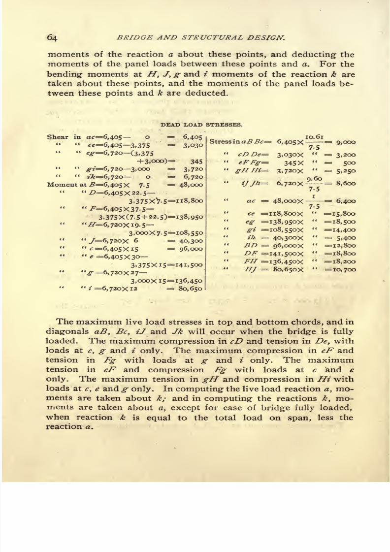
7/30/2019 Bridge Structural 00 Thom Rich
http://slidepdf.com/reader/full/bridge-structural-00-thom-rich 74/104
64 BRIDGE AND STRUCTURAL DESIGN.
moments of the reaction a about these points, and deducting the
moments of the panel loads between these points and a. For the
bending- moments at H, J, g and i moments of the reaction k aretaken about these points, and the moments of the panel loads be-
tween these points and k are deducted.
DEAD LOAD STRESSES.
Shear in #=6,405 o =6,405
" "^=6,405 3,375
=3,030
^=6,720 (3,375
+3,000)= 345<
-7=6,7203,000 =3,720
" "zVfe=6, 720- o ==
6,720
Moment at ^=6,405X 7-5= 48,000
".0=6,405x22.5
3,375XV-5=n8,8oo
"^=6,405x37-5-
3>375X(7.5+22.5)=i38,95o
"^=6,720X19.53,000X7.5=108,550
"/=6,720X 6 =40,300
"^=6,405x15 =96,000" "
e =6,405X30
3,375Xi5=i4i,5oo
3,000x15=12 =
80,650
Stress inaBBc= 6,4O5X

7/30/2019 Bridge Structural 00 Thom Rich
http://slidepdf.com/reader/full/bridge-structural-00-thom-rich 75/104
Reaction a. Bridge fully loaded =
SKEW WARREN GIRDER.
LIVE LOAD REACTIONS.
[SiooX 12] 4- [90ooX(27+42+57)l
72
[8100X12] + [ooooX(27+42)]a. Loads at e, g and t=
a. Loads at g- and t =
72
(8100X12)4- (9000X27)
72
k. Bridge fully loaded =8100+(9000X3) 17100
9oooX(i5+3o+45)k. Loads at c, e andg=
:. Loads at c and e =
72
9ooox(i5+3o)
72
65
=17,100
= 9,970
=4,725
=18,000
=11,250
= 5,625
LIVE LOAD STRESSES.
Shear in ac =17,100*'
" " ce= 9,970
<gr=
4,725?*.
^ 5>625" "
^'=11,250"
/ft =18,000
Moment at ^=17, iooX 7-5"Z>=i7, 100x22. 5
9,oooX7-5=
9,ooox(7-5+22.5>
"^7=18,000x19.5
8,iooX7-5=
"/=i8,ooox 6
"^=17,100X15 =
41
^=17,100x30
9,000x15=" g =18,000x27
8,100x15='
z =18,000X12 ,.
17,100
9,970
4,725
5,625
11,250
18,000
128,000
317,500
371,250
290,250
108,000
256,500
=378,000
=364,500
=216,000

7/30/2019 Bridge Structural 00 Thom Rich
http://slidepdf.com/reader/full/bridge-structural-00-thom-rich 76/104
66 BRIDGE AND STRUCTURAL DESIGN.
I/

7/30/2019 Bridge Structural 00 Thom Rich
http://slidepdf.com/reader/full/bridge-structural-00-thom-rich 77/104
SKEW WARREN GIRDER.
tally. This will necessitate double gusset plates, and all angles will
require to be latticed.
Floor Beams, Fig. 62:
Dead load (floor)= 250 Ibs. x 15'
=3,750
Dead load (beam) =say 750
Live load = 16' x 15' x 100 Ibs. =
Total
Reaction =
4,500
24,000
28,500 Ibs.
28,500 = 14,250 Ibs. Moments at centre =
(14,250 x 8.75) (14,250 x 4)=
14,250 x (8.74 4)=
67,700 ft.-lbs.
67,700 x 12 = 812,400 inch-lbs. Then, 812,400-=-
15,000=
54.16=
R required.
A 15" I at 42 Ibs. will be used. R = 58.9.
Laterals, Fig. 60. It will be sufficiently accurate to assume that
the horizontal truss consists of five
equal panelsof 1
5'
o"each,
and
17' 6" deep. The length of the diagonals= V J 52 + J 7' 6"
2= 23.04
ft. One-half the wind force is to be treated as a stationary or dead
load, and one-half as a moving or live load, then
Panel dead load =150 Ibs. x 15'=
2,250 Ibs.
"live
" =150 Ibs. x 15'
=2,250 Ibs.
The maximum shear in panel a c is when the live load covers the
span.
The maximum shear in panel c e is when the live load is at e, gand i only.
The maximum shear in panel e g is when the live load is at g and
i only.
ist lateral =
DEAD LOAD STRESSES.
23.045,94O
2d " = 2,75oXiX" = 2,970
3rd " = == o
2,250 X 2 X
2,250 X | X
2,250 X | X
LIVE LOAD STRESSES.
23.04
17-5
=5,940
=3,560
= 1,780
The total stresses, the areas required and provided are shown in
Fig. 60.
Floor beam connection, Fig. 63. The reaction = 14,250 Ibs. and
the rivets connecting the end angles with the truss are in direct

7/30/2019 Bridge Structural 00 Thom Rich
http://slidepdf.com/reader/full/bridge-structural-00-thom-rich 78/104
68 BRIDGE AND STRUCTURAL DESIGN.
shear; therefore, 14,250 -5- 3,310=
5 rivets required, whereas the
drawing shows 6 rivets. In addition to the vertical load on rivets
connecting the end angles with webof
beam,these
rivets arere-
quired to resist a bending moment equal to the reaction mulitplied
by the distance from back of angle to centre line of rivets. The
greatest stress, due to bending, is on the rivets farthest from their
centre of gravity and is equal to the bending moment, divided by
the moment of resistance of rivets. The direction of this stress is
horizontal. The centre of gravity of rivets and their distances from
this point are shown in Fig. 63.
The bending: moment = 14,250 Ibs. X 1.75" = 24,900 in.-lbs.
The moment of inertia of rivets is obtained by multiplying each
rivet by the square of its distance from the center of gravity, as
follows :
1= 2 rivets x 1.52=
4.5
2 rivets x 4.52=
40.5
45-0
The moment of resistance is equal to the above result divided
by the distance from centre of gravity to farthest rivet, thus :
45
4-5
Stress on outer rivets from bending = 24,900 in.-lbs. -f- 10 =2,490 Ibs.
Stress on outer rivets from direct load = 14,250 Ibs. ~-4 =
3,560 Ibs.^
Resultant stress on outer rivets = V 2,49O2 + 3,5602
= 4,340 Ibs.
The web of beam is f"
thick, therefore, the bearing value of one
| rivet = f" x f x 15,000 Ibs. = 4,570, which is greater than the
maximum stress on rivets.
The other details, Fig. 64, are self-explanatory.
ART. 22. DESIGN FOR A PIN-CONNECTED PRATT TRUSS HIGH-WAY SPAN. (FIG. 65.)
Data: Length, 120' o", centre to centre of end pins. 8 panels
of 15' o".
Depth, 20' o".
Roadway, 16' o" clear. Trusses, 17' o", centre to centre.

7/30/2019 Bridge Structural 00 Thom Rich
http://slidepdf.com/reader/full/bridge-structural-00-thom-rich 79/104
SKEW WARREN GIRDER.
* .*

7/30/2019 Bridge Structural 00 Thom Rich
http://slidepdf.com/reader/full/bridge-structural-00-thom-rich 80/104
70 BRIDGE AND STRUCTURAL DESIGN.
Dead load (steel)= 2 x L + 50 290
"(floor)
=250
Total, per lineal foot = 540 Ibs.
Live load, 75 Ibs. per square foot. Then 75 Ibs. x 16' =1,200 Ibs. per lineal foot for trusses.
Live load, 100 Ibs. per square foot for floor beams and
hip verticals.
Wind force for top laterals, 150 Ibs. per lineal foot, to be
treated as dead load.
Wind force for bottom laterals, 150 Ibs. per lineal foot, to
be treated as dead load.
Wind force for bottom laterals, 150 Ibs. per lineal foot to
be treated as live load.
STEEL IRON
Unit stresses: Tension. 1 5,000 12,000 for bottom chords, main
diagonals and floor
beams.
9,000 for counters and hip ver-
ticals..
8,000 for floor beam hangers.
15,000 for laterals.
STEEL
Compression, 12,000 reduced by Rankine's formula (Art. 12). Nomember to have a length exceding 120 times
its least radius of gyration ;end and inter-
mediate posts to be considered as columns
with two pin ends;end sections of top chord
as columns With one pin and one square
end; intermediate sections of top chord as
columns with square ends.
Shearing, 10,000 for pins and shop rivets.
"7>5OO for field rivets.
Bearing, 20,000 for pins and shop rivets.
"15,000 for field rivets.
Bending, 22,500
for pins.
PANEL LOADS FOB ONE TRUSS.
540Dead Load = Xi5'
= 4,000 Ibs. Length of diagonals=
-v/i58
-h2o8 =
25'.
1200Live Load =
Xi5'=
9,000 Ibs.
Dead Load Reaction = 4000X3^ = 14,000 Ibs.

7/30/2019 Bridge Structural 00 Thom Rich
http://slidepdf.com/reader/full/bridge-structural-00-thom-rich 81/104
PIN-CONNECTED HIGHWA Y SPAN.'
DEAD LOAD STRESSES.
Shear in panelab= 14,ooo
Moment at B
=14,000
4,000=10,000
^=14,000 8,000= 6,000
cfe=I4,000 12,000= 2,000
"= 14,00016,000= 2,OOO
=i4,oooX I 5 =210,000
14,000X30
4,oooX 15=360,000=
14,oooX4S
4,ooox(i5+3o)=45o,ooo
e =14,000X604,ooox(i5+3o+45)=48o,ooo
Stress in aB
BeCc
Cd
DdDe
Ee
Efabc
17,500
io,oooxf= 12,500
6,oooX i = 6,000
6,oooxf= 7>5oo
2,OOOX I = 2,OOO
2,OOOXf<T= 2,500
2,OOOX I = 2,000
DE =
210,000X^7= 10,500
360,oooXA 18,000
= 22,500= 24,000
For the stress in a b c moments are taken about panel point B.
For the stress in B C moments are taken about c, and for the stress
c d moments are taken about C. But since c and C are the same
distance horizontally from a, the stresses in B C and c d are equal.
Likewise the stresses C D and d e are equal.
LIVE LOAD REACTIONS.
Bridge fully loaded 9,oooX3K ==3 I 5 o Iks. for maximum stresses in chords and
end posts.
Loads at c, d, e,f, g and 7i, 9,oooX\1-==
23,6oo Ibs. for maximum stress in Be.
Loads at d, e,f, g and h, g,oooy^i/-=i6,goo Ibs. for maximum stresses in Cc and Cd.
Loads at e,f, g and h, g,ooo'X=ii,2$o Ibs. for maximum stresses in Dd and De.
Loads at/, g and h, 9,000x1=6,750 Ibs. for maximum stresses in Ee and Ef.
LIVE LOAD STRESSES.
Shear in panel ab" "
be
" cd" " de
"ef
Moment at B 31,500X15" "
^C 3 1,500x309,000x15
9,ooox(i5+3o)"
e 31,500X60
9,ooox(i5+3o+45)
31,500
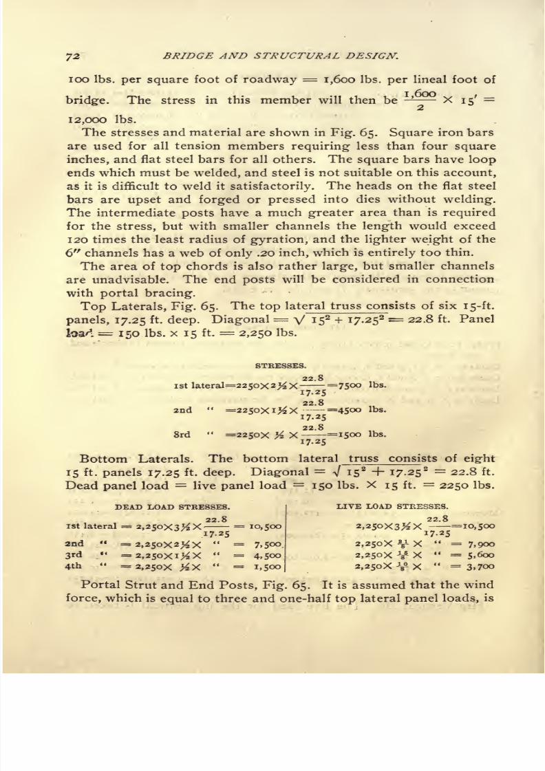
7/30/2019 Bridge Structural 00 Thom Rich
http://slidepdf.com/reader/full/bridge-structural-00-thom-rich 82/104
72 BRIDGE AND STRUCTURAL DESIGN.
100 Ibs. per square foot of roadway = 1,600 Ibs. per lineal foot of
bridge.The stress in this member will then be -- X
15'
=
12,000 Ibs.
The stresses and material are shown in Fig. 65. Square iron bars
are used for all tension members requiring less than four square
inches, and flat steel bars for all others. The square bars have loop
ends which must be welded, and steel is not suitable on this account,
as it is difficult to weld it satisfactorily. The heads on the flat steel
bars are upset and forged or pressed into dies without welding.
The intermediate posts have a much greater area than is required
for the stress, but with smaller channels the length would exceed
120 times the least radius of gyration, and the lighter weight of the
6" channels has a web of only .20 inch, which is entirely too thin.
The area of top chords is also rather large, but smaller channels
are unadvisable. The end posts will be considered in connection
with portal bracing.
Top Laterals, Fig. 65. The top lateral truss consists of six 15-ft.
panels, 17.25 ft. deep. Diagonal= V J 52 + I 7-252 = 22 -8 ft- Panel
. = 150 Ibs. x 15 ft. = 2,250 Ibs.
STRESSES.
22.8
ist lateral=225ox 2> X- =75oo Ibs.
22.8
2nd " =22oXiX---=45oo Ibs.
22.8
8rd"
=2250X # X-=1500 Ibs.
Bottom Laterals. The bottom lateral truss consists of eight
15 ft. panels 17.25 ft. deep. Diagonal= V IS
2 + i7-252
22.8 ft.
Dead panel load = live panel load = 150 Ibs. X 15 ft.=
2250 Ibs.
DEAD LOAD STRESSES.
22.8
ist lateral = 2,2$oX3#X
- = 10,500I7-25
2nd " = 2,250x2^ X" =
7,5oo
2,250x3^ X i7~io, 500
2,25oX V- X" =
7,900
2,25ox V- X "=5,600
2,250X Y X "=3,700
Portal Strut and End Posts, Fig. 65. It is assumed that the wind
force, which is equal to three and one-half top lateral panel loads, is
3rd' = 2,25oxi^X
" =4,500
4th" =
2,25ox >X " =1,500
LIVE LOAD STRESSES.

7/30/2019 Bridge Structural 00 Thom Rich
http://slidepdf.com/reader/full/bridge-structural-00-thom-rich 83/104
PIN-CONNECTED HIGHWA Y SPAN.73

7/30/2019 Bridge Structural 00 Thom Rich
http://slidepdf.com/reader/full/bridge-structural-00-thom-rich 84/104
74 BRIDGE AND STRUCTURAL DESIGN.
applied at the top of portal strut, and that it is resisted equally at the
foot of both end posts. It is also assumed that the posts, although
hingedat
the bottomin
plane of trusses, are fixed in the plane ofthe portal, and that the plane of contra-flexure is midway between
the foot of posts and the lower extremities of portal struts. Then
in figuring the portal stresses the ends of ports may be considered
to lie in this plane of contra-flexure. The problem of finding the
stresses in a portal strut is similar to that of finding the wind
stresses in a roof truss supported on and braced to steel columns
as explained in Art 17,
The force applied at top of portal = 2,250 x 3^ = 7,875 Ibs.
The horizontal reaction at foot of each post = 7,875 x \ = 3,935
Ibs.
Since the plane of contra-flexure is assumed to be midway be-
tween the foot of posts and connection of knee braces, the mo-
ments at these points will each be equal to 3,935 Ibs. x 7.5'=
29,500 ft.-lbs. The moment at foot of post is resisted by the direct
thrust in post acting with a lever arm equal to one-half the width
of bearing plates. The moment at knee brace connection is re-
sisted by a force at top of post acting with a lever arm of 10 ft.
Therefore, this force = 29,500 ft.-lbs. -=- 10' = 2,950 Ibs. This
force of 2,950 Ibs. induces tension of the same amount on leeward
side of top strut, and compression on the windward side, but in the
latter case the applied force of 7,875 Ibs. should be added. There-
fore the total compression on windward side of top strut = 2,950 +7,875
=10,825 Ibs. The horizontal force at the lower end of knee
braces is equal to the induced force at top of posts, plus the hori-
zontal reaction at foot of posts=
2,950 + 3,935=
6,885 Ibs.; and
the stress in the knee braces is equal to this latter force, multiplied
by length of knee brace and divided by one-half the width of portal
13.2=6,885 x =
10,540 Ibs. This stress will be tension on the
8.62
windward side of portal and compression on the leeward side.
There are no stresses in the members shown in dotted lines ; they
help to stiffen the main members, and give a more pleasing appear-
ance to portal. As the stresses are all light, it is only necessary to
proportion the members so that their length shall not exceed 120
times their least radius of gyration.
The posts should be proportioned so that the maximum fibre

7/30/2019 Bridge Structural 00 Thom Rich
http://slidepdf.com/reader/full/bridge-structural-00-thom-rich 85/104
PIN-CONNECTED HIGHWAY SPAN*. 75
stress resulting from the combined action of the dead load, live,
load and wind force shall not exceed by more than 25% the permis-
sible unit strees for dead and live loads only.
The direct stress in post as shown in Fig. 60 = 56,900 Ibs.
The bending moment as above = 29,500 x 12 = 354,000 inch-lbs.
The area of the section assumed = 14.31 square inches, and its
moment of resistance about an axis perpendicular to the cover plate
=53-8.
Then: Direct stress -*- area = 56,900 Ibs. -*-14.31
=3,970
Bending- moment -*- R = 354,000 in.-lbs. * 53.8 = 6,580
Total, 10,550 Ibs.
per square inch.
The permissible unit stress = 7,870 + 25% =9,835 Ibs. per sq.
inch. Thus the post is stressed slightly too much to fulfill the con-
ditions, but the assumed wind force is probably much greater than
the actual.
The intermediate top struts, Fig. 65, are in this case made similar
to the portal struts. They are not proportioned for any definite
stress, but nevertheless they contribute to the stiffness of the bridge,
and relieve the portal struts and end posts from a portion of their
wind stresses.
Floor Beam. Span, 17.25 ft.
Dead load (floor) = 250 x 15' = 3,750
(beam) 650
4,400
Live load = 1,600 X 15=
24,000
Total (distributed over a length of 16 ft.)= 28,400 Ibs.
Reaction = 28,400 x J= 14,200 Ibs.
Taking
moments about the center, M = 14,200 x 8,625 14,200
X 4 = 65,675 ft.-lbs., 65,675 X 12 = 788,100 inch-lbs., 788,100 -*
1 5,000== 52.7 ==R.
A 15" I @ 42 Ibs. will be used. R= 58.9.
Pin Moments. The pins in the bottom chord and the one at the
hip usually receive their maximum moment when the bridge is fully

7/30/2019 Bridge Structural 00 Thom Rich
http://slidepdf.com/reader/full/bridge-structural-00-thom-rich 86/104
76 BRIDGE AND STRUCTURAL DESIGN.
Lvng of Tfu%
HO^MOHTM. 5tci\<m ?m oFig.
66
S.CT\OK ?\r\ B Fig. 6?
nORtZOHTM-StCTlOn Pm cFig.
69

7/30/2019 Bridge Structural 00 Thom Rich
http://slidepdf.com/reader/full/bridge-structural-00-thom-rich 87/104
PIN-CONNECTED HIGPIWAY SPAN. 77
loaded, but the other pins in top chord will be subjected to their
maximummoment, simultaneously
with the
maximumstress in
main diagonals connecting thereto. Before figuring the pin mo-
ments, it is necessary first to find the stresses in all the members
which are connected by pin for the condition of loading giving the
maximum moment on pin. The stresses in the diagonal members
should be resolved into their vertical and horizontal components,
and the vertical and horizontal moments figured separately. The
resultant moment at any point will be equal to the hypothenuse of
a right angled triangle whose vertical and horizontal sides are
equal respectively to the vertical and horizontal moment on pin.
Having found the maximum moment, the size of pin required is
obtained from a table similar to that in Carnegie p. 183, giving the
maximum bending moment allowable on pins of various sizes.
The values are obtained by multiplying: the R of pin by the allow-
able stress per square inch on outer fibres in this case 22,500 Ibs.
A pin may be large enough for the bending moment and yet too
small for bearing ; so care must be taken to ensure that the bearing
of all members on the pin does not exceed the allowable amount,
which, in the present example has been taken at 20,000 Ibs. per
square inch.
Pin a, Fig. 66. The vertical component of the stress in end
post is equal to this stress multiplied by depth of truss and divided
20
by length of post=
56,900 x =45,500. The horizontal com-
25
ponent is equal to stress in post multiplied by length of panel and
15
divided by length of post=
56,900 x = 34,100 Ibs.
25
In order to determine the distances between the members, the
joint is sketched to a large scale as shown. It is only necessary to
consider the forces on one side of the centre line of truss, whichare as follows : on the shoe, an upward force equal to one-half the
vertical component of stress in end post=
22,750 Ibs.;on end
post, a downward force of 22,750 Ibs., and a horizontal force acting
towards the left of 17,050 Ibs.;and on the chord bar, a horizontal
force to the right of 17,050 Ibs. The sum of the forces acting in one
direction must always equal the sum of the forces acting in the

7/30/2019 Bridge Structural 00 Thom Rich
http://slidepdf.com/reader/full/bridge-structural-00-thom-rich 88/104
78 BRIDGE AND STRUCTURAL DESIGN.
opposite direction. The vertical and horizontal forces are shown
plotted on separate diagrams. Then:
Vertical Momenta. Horizontal Moments.
At b = 22,750 X #"'=
17,050 At b = 17,050 X %" = 12,800
At c = 17,050 At c = 17,050 X i#" = 29,850
Resultant Moment.
At c = -/I7.0503
-f-29,8508=34.400 inch-lbs.
Now, from table of pin moments in column for 22,500 Ibs. fibre
stress,it will be found that a
2^" pinhas a value of
34,500inch-lbs.
As stated above, the pins in the bottom chord and at the hip
usually receive their maximum moment when the bridge is fully
loaded. It will therefore be necessary to figure the stresses in the
web members for this condition of loading before proceeding
further. The dead and live loads may be taken together and the
total stresses found in exactly the same manner as for dead load
only. The total panel load = 4,000 + 9,000= 13,000 Ibs. Reaction
= 13,000 Ibs. x 3^ panel= 45,500 Ibs.
DEAD AND LIVE LOAD STRESSES IN WEB MEMBEBS; BRIDGE FULLY LOADED.
Shear in panela&=45, 500 0=45,500" "
#=45,500 13,000=32,500"
rc?=45,5oo 26,000=19,500" "
cfe=45, 500 39,000= 6,500
Stress in aB = 45, SOD X f=
56,900
Be = 32, 500 X \\= 40,600
" Cc=* 19,5 X 1=19,500Cd = 19, 500 X f$
= 24,400" Dd= 6,500 X I = 6,500
De= 6,500 XH= 8,100
For the pin moments the stress in the hip vertical and in all floor
beam hangers will be taken as an ordinary panel load, viz. :
13,000 Ibs.
Pin B. When the bridge is fully loaded, the vertical and horizon-
tal components of the stresses in the various members connected by
this pin are as follows :
Members. Vertical Components. Horizontal Components.
End Postal 56,9ooxf=455oo 56,900x^=34,100Tie Bar Be 40,600x1^=32,500 4o,6ooxif=24'4oo
Hip Vertical Bb 13,000 o
Top Chordae o 58,500
One-half of the above vertical and horizontal forces are plotted
in separate diagrams, Fig. 67.

7/30/2019 Bridge Structural 00 Thom Rich
http://slidepdf.com/reader/full/bridge-structural-00-thom-rich 89/104
PIN-CONNECTED HIGHWAY SPAN.. 79
Vertical Moments. Horizontal Moments.
Atb=22,75oxX" =n,375 At b=i7,o5oxK =8,525
At 0=22,750x1^" =39,800 At 0=17,050X1^29,500x1^=6,800At d=22,75ox 3 i6,25oxiX=47,95o At d =6,800
Resultant Moment.
At d='l/47,-95o~+ 6,800^=48, 500.
Consequently, a 2j" pin which has a value of 52,500 inch-lbs. is
the size required.
Pin C, Fig. 68. The condition for maximum moment on this pin
is when the bridge is loaded from d to h. The stresses C c andC d are as shown on stress diagram Fig. 65. Since the top chord
is continuous at this point, it is only the difference of the stresses in
B C and C D which need be considered, and this is evidently equal
to the horizontal component of the stress in C d.
The vertical and horizontal components of stresses in members
are as follows :
Members. Vertical Components. Horizontal Components.
Top chord CO o 28,600X \\=17, 150
Tie bar Cd 28,6ooXfg=22, 900 28,600X^1=17,150
Post Cc 22,900 o
Vertical Moments. Horizontal Moments.
Atb= o Atb=8,575Xi^= I0.7oo
At c= 1 1,450X^=10,000 Ate 10,700
Resultant Moment.
At c=i/io,ooo2+ io,oo
2=i4,6oo inch-lbs.
A 2" pin which has a bending value of 17,700 inch-lbs. is the size
required. This size may also be used at D and E.
Pin c, Fig. 69. When the bridge is fully loaded, the vertical and
horizontal components of the stresses in the various members con-
nected by this pin are as follows :
Members. Vertical Components. Horizontal Components.
Chord bar be o 34,ioo
Chord bar cc? o 58,500
Tie bar Be 4o,6ooXf =32,500 40,6ooX if=24,400
Post Cc 19,500 o
Floor beam hanger 13,000 o

7/30/2019 Bridge Structural 00 Thom Rich
http://slidepdf.com/reader/full/bridge-structural-00-thom-rich 90/104
So BRIDGE AND STRUCTURAL DESIGN:
H-m+H^ Centre Line
KWiWeam^hanger lo
y Chordjbar
<?/> jfrtr
of Truss a
HORIZONTAL SLCTION Plrt ^Fig-7O
YERTICAU
YORCK> FORCE*
I ,. CenTrg Line, ,<& Try ss
Tie bar
'llCotjinTerp
IWHNfl m
bar cJ l|
- r^tcoq
lrr ^7|
:
'
''''^LcViowi bar ^~
i^^Or^M 2>x%
r-. .
StCTiOK PVH d Ylg.7l ,
FORCES
floorbgam B fn^ii
Centre Line of TTUSS e
hangerTo
... 1
[Chord bar^ 3 X
:q_
! Tie ba. gf g^r
VtRTlCAV

7/30/2019 Bridge Structural 00 Thom Rich
http://slidepdf.com/reader/full/bridge-structural-00-thom-rich 91/104
HIGHWAY SPAM. 8 1
Vertical Moments. Horizontal Momenta.
Atb= o At b= 1 7,050X1^ =19,200
Atc= o At 0=17,050X2^ 29,250X1^= 5,6oo
Atd=i6,25oxi 16,250 Atd== 5,600
At e=i6,25o=4} 9,750X3^=36,500 Ate= 5,600
Resultant Moment.
At e = -v/36.5003 + 5,6oo
3 =37.000.
Thus a 2 pin which has a bending value of 40,000 in.-lbs. is the
size required.
Pin b t Fig. 70. When the bridge is fully loaded, the vertical andhorizontal components of the stresses in the various members con-
nected by this pin are as follows :
TVTAmHArfl Vertical Horizontal
Components. Components.
Chord bar ab o 34,ioo
Chord bar be o 34, 100
Hip vertical Bb 13,000 o
Floorbeam hanger 13,000
o
The chord bars a b and b c should be spaced so that they will pull
in as nearly a straight line from a to c as possible. By reference to
Fig. 66, the distance from center line of truss to center line of chord
bar will be found to be 3f"
;and in Fig. 69, the center of chord bar
b c is 6f" from center line of truss. The average of these distances
is about 5", which should be the distance to the centre of the two
chord bars at b, as shown in Fig. 70. The object of the spacing an-
gle between the hip vertical and chord bar a b is to hold the top of
floor beam at the proper distance below pin.
Vertical Moments. Horizontal Moments.
At b= o At b=i7,050X1^=23,500
Atc= o At c =23,500
At 6=6,500x2^=17.ooo Atd =23,500
Resultant Moment.
At d= 17,000* -fc 38,500*- 29,000.
A 2}^" pin which has a bending- value of 34,500 inch-lbs. is the size
required.
Pin d, Fig. 71. When bridge is fully loaded, the vertical and

7/30/2019 Bridge Structural 00 Thom Rich
http://slidepdf.com/reader/full/bridge-structural-00-thom-rich 92/104
82 BRIDGE AND STRUCTURAL DESIGN.
horizontal components of the stresses in the various members con-
nected by this pin are as follows :
Member. Vertical Component. Horizontal Component.
Chord bar cd o58,50x3
Chord bar de o 73,ooo
Tie bar Cd 24,4ooxfir=i9>5oo 24, 400XM^ 1 4- 500
Post Dd 6,500 o
Counter dE o o
Floor beam hanger 13,000 o
Vertical Moments. Horizontal Moments.
Atb=o
Atb=29,25ox7
/% =25,600Atc= o At 0=29,250X1^ 36,500X1=18,500
Atd=9,75oX%= 8,500 Atd= 18,500
At 6=9,750x4 3,250x3^=28,800 Ate= 18,500
Resultant Moment.
At e = 1/28, 8oo8 + i8,5oo
3 =34,200.
A 2^" pin which has a bending value of 34,500 inch-lbs. is the size
required.Pin e, Fig. 72. When the bridge is fully loaded the vertical and
horizontal components of the stresses in the various members con-
nected by this pin are as follows :
Members. Vertical Components. Horizontal Components.
Chord bar ef o 73,ooo
Chord bar de o 73,ooo
Tie bar eF 8,iooxf=
6,500 S.iooXsf 4. 9
Tie bar De 8,iooxf5= 6,500 8,iooxif= 4, 900Post Ee o o
Floor beam hanger 13,000 o
Vertical Moments. Horizontal Moments.
Atb= o At b=36, 500X1 36,500
Atc= o At 0=36,500X2 36.500X1= 36,500
At =3,250X1= 3.250 At d=36, 500X3 36,500X2+2,450X1=38,900At 6=3,250x5+3-250X4=29,250 Ate= 38,900
Resultant Moment.
At e= 1/29, 250s
+- 38, ooo3 =
48, 700.
A 2j" pin which has a bending value of 52,500 inch-lbs. is the size
required.
The size of pins required at the various panel points, as deter-

7/30/2019 Bridge Structural 00 Thom Rich
http://slidepdf.com/reader/full/bridge-structural-00-thom-rich 93/104
PIN-CONNECTED HIGHWA Y SPAtf. 83
mined above, are as follows : 2J" at 5 and e; 2f
"at r
; 2j" at a, 6
and d; and 2" at C, Z) and E. But, in order to simplify the shop
work as much as possible, 3" pins will be used throughout, except2" pins at C, D and E.
The pins in the top chords and end posts should be placed as near
the centre of gravity of the section as practicable. In the present
example this centre of gravity will be found to be a little more than
one inch above the centre line of channels, but it would be incon-
venient to set the pins at this height as there would not be space
enough for some of the bar heads, so they are located one-half inch
above centre line of channels or three inches below top flange. This
arrangement gives just room enough for the largest bars at panel
point B, where the space required equals one-half the diameter of
pin, plus the thickness of bars,= i%' + 1^4"
= 2 7/%" , leaving >6"
clearance between bars and cover plate.
Shoes, Rollers and Bed Plates. Fig. 73.. The total load on the
shoes is equal to the vertical component of strefss in end post=
56,900 X ||=
45,500 Ibs. Then, since the permissible bearing1
for pins = 20,000 Ibs. per square inch, 45,500 -f- 20,000 = 2.27
square inches required for shoe standards. Two 7 x 3^ x-JLs have
been used, and the bearing area of pin on these = -J" x 3" x 2 = 3
square inches. This is somewhat more than required, but it is well
to make these members quite stiff. It is difficult to determine the
exact thickness to make the shoe plates and bed plates, and this
matter is usually left to the judgment of the designer. In the
present case these have been made f" thick. The area of the bed
plates should be great enough so that the pressure on the masonry
will not exceed 300 Ibs. per square inch. They must also be large
enough to accommodate the rollers and the anchor bolts. The
bearing area required= 45,500-^-300
=152 square inches. The
area of bed plates used = 12" x 22"= 264 square inches.
The rollers should be designed so that the pressure on them per
lineal inch shall not exceed 600 V diameter. Assuming 2j" rollers,
the permissible bearing= 6oc V 2-5"
=95 Ibs., then 45,500
-~
950 = 48 lineal inches required. There are 4 rollers and the ef-
fective length of each = 16" 2j" = 13!". Then 4 x 13! = 55
lineal inches provided. The rollers are turned down at center to
pass over guide strips on shoe and bed plates, and the ends are
turned down to enter holes in the 2\ x 5/16 spacing bars, as shown.
The ends of the outer rollers are made long enough to insert cotter

7/30/2019 Bridge Structural 00 Thom Rich
http://slidepdf.com/reader/full/bridge-structural-00-thom-rich 94/104
84 BRIDGE AND STRUCTURAL DESIGN.

7/30/2019 Bridge Structural 00 Thom Rich
http://slidepdf.com/reader/full/bridge-structural-00-thom-rich 95/104
PIN-CONNECTED HIGHWAY SPAN, 85
pins, but the ends of the intermediate rollers just pass through the
spacing bars.
The shoe plates are extended, as shown, to provide connectionsfor the end laterals, which are made with forked eyes.
The fixed end bed plates are made of cast iron, and their height
is equal to the diameter of rollers plus the thickness of roller beds
- 2^ + X =3#".
The anchor bolts should have sufficient cross section to resist the
total shear from the assumed wind force in plane of bottom chords,
plus one-half of the wind force on portal strut. In the table of
lateral stresses the dead and live load shears in each panel each =2,250 x 3j
=7,875 Ibs., and the wind force at top of portal also
equals 7,875 Ibs. Then the total force to be resisted by anchor
bolts = 7,875 X 2^ =19,700. The area of two i#" bolts = 2.45
square inches, and their shearing value = 2.45 x 10,000 Ibs. =24,500 Ibs.
End Post and Top Chord. The stress in end post = 56,900 Ibs.,
and the permissible pin bearing 20,000 Ibs. per square inch, then
56,900 -T- 20,000 = 2.84 sq. inches required. The diameter of pins
=3", therefore thickness of bearing required
=2.84 -f- 3
=.95".
The thickness of the webs of the 7" [s @ 14.75 Ibs.= Vie"- In addi-
tion, Vie" pin plates are used, making the total thickness of metal
(yV + A) x 2 =.i^". The amount of bearing: on the pin plates
will be in the ratio .of their thickness to the total thickness of bear-
. f
ing= 56,900 x =23,700. There should be sufficient rivets in
ii
pin plates to meet this stress. The single shearing value of one f"
rivet= 4,420 Ibs., then 23,700 -f- 4,420= 6 rivets required ;8 rivets
are shown 4 in each plate. At the upper end of posts, the pin plates
extend beyond the post, forming what are called jaw plates. The
pin plates on top chord at this point also extend beyond pin, but are
on the inside of channels, as shown.
The stress in top chord B C 58,500 Ibs., then 58,500-^20,000
= 2.92 square inches bearing required; and 2.92 -f- 3 = .97" =thickness of bearing required. The webs of the 7" [s at 12.25 Ibs.
are 5/16
"thick, and 5
/16"
pin plates are used, making the total
thickness of bearing (5/16 + Vie) x 2 Ii"- The amount of bearing
on pin plates will then be 58,500 x-J= 29,250 Ibs. The number of
y rivets required =29,250-1-4420= 7. Between the end post

7/30/2019 Bridge Structural 00 Thom Rich
http://slidepdf.com/reader/full/bridge-structural-00-thom-rich 96/104
86 BRIDGE AND STRUCTURAL DESIGN.
and top chord a space of \n
is left to ensure that the whole bearing
will come on pin.
At panel point C the top chord is continuous, and it is only nec-
essary to provide sufficient bearing- for the horizontal component of
the stress in tie bar C d, which is equal to 28,600 x Jf =17,150Ibs. Then 17,150
-=- 20,000 =.85 square inches required, and .85
-r- 2.25=
-.38"= thickness of bearing required. The webs of the
two channels = f", thus no pin plates are required.
The top chord is spliced i' o" from panel point D. Since this is
a faced joint, the stresses are transmitted directly by the abutting
surfaces, and thesplice plates
arerequired only
to hold the mem-
bers in line.
The bent channels on the top chord are lateral connections. The
lateral rods, which are J" diameter, are upset at the ends to ij",
and threaded for standard nuts. Plate washers, f" thick, are used
to screw up against the ends of bent channels.
Intermediate Posts. The stress in post Cc = 22,900 Ibs., then
22,900-^-20,000=
1.14 square inches bearing area required on
pins. The diameter of the upper pinis
2j", therefore 1.14-7-2.25= .50= thickness of bearing required. Two f"
pin plates are used
at top and bottom of all posts. The posts must be wide enough to
permit the floor beam hangers to pass between the channels as
shown. The number of f" rivets required in pin plates=
22,900
-5- 3>O7O= 8, whereas there are 12 rivets provided.
Bars. The loop ends of the square iron bars are made by bend-
ing the ends of the bar around a pin and welding these ends to the
body of bar. The distance from centre of pin to crotch should be
2\ times the diameter of pin. The heads of the flat steel bars are
made by upsetting the ends of the bars and forging in dies of the
required size. The heads are made round and of such diameter as
to give an area through centre line of pin hole 50% greater than
that of body of bar. Thus the width of bars = 3", diameter of pins
=3" then 3" + 3" + i#" = 7^" = diameter of heads.
Pins are turned down or shouldered at the ends and provided with
chambered nuts to ensure a full bearing for the outer members.Floor Beams. The end reaction of floor beams = 16,000 Ibs. and
the unit stress for floor beam hangers = 8,000 Ibs. per square inch,
therefore 16,000-^-8,000= 2 square inches required in hangers.
The hangers are made of i" square iron, bent to fit over pins and
upset to i-J" round at ends and threaded for nuts as shown in Fig.

7/30/2019 Bridge Structural 00 Thom Rich
http://slidepdf.com/reader/full/bridge-structural-00-thom-rich 97/104
PIN-CONNECTED HIGHWAY SPAN.

7/30/2019 Bridge Structural 00 Thom Rich
http://slidepdf.com/reader/full/bridge-structural-00-thom-rich 98/104
88 BRIDGE AND STRUCTURAL DESIGN.
73. The main nuts are of the same thickness as diameter of thread,
and the lock nuts are i" thick. The top and bottom flanges of the
beams are notched as shown in Fig. 74, and on the bottom there is
a washer plate 4" x f x 8". The floor beams are screwed up firmly
against the ends of the posts, which extend below the pins at c, d
and e far enough to clear the largest bar heads. At panel point b,
where the vertical members are rods, spacing angles are used to
hold the beam at the same distance below the pins.
Bottom Laterals. The end laterals which are ij" square are
forked at one end to connect with the shoe plate as shown in Fig. 73.
At the opposite end they are upset to if" round and threaded for
standard nuts.. These upset ends pass through holes in the web of
floor beam b, and between the lug angles which are riveted to the
web of floor beam, and cut at right angles to centre line of lateral
rods as shown in Fig. 74. The pins connecting laterals with shoe
plates may be considered as girders supported at both ends and
having a concentrated load at the center equal to the stress in
lateral. The distance centre to centre of forks is about 2", then
Wl 21.000X2M = = =
10,500 inch-lbs., which requires a if" pin.
4 4
For uniformity this size will be used throughout.
The laterals in the 2d panel, which are i" square, have plain loop
eyes at one end to connect with the lug angles on floor beam b. At
the opposite end they are upset to ij" round, and pass through
holes in the web of the floor beam c, and between the lug angles
riveted thereto.
The laterals in the 3d panel, which are 7/%" square, have plain loop
eyes to connect with the lug angles on floor beam c, and are upset
to if" round at opposite end and pass through holes in web of
floor beam d, and between the lug angles riveted thereto.
In one panel adjacent to the centre of the span there will be a
pair of laterals J" square with loop eyes at both ends. These rods
are made in two parts and provided with turnbuckles for adjust-
ment.
The lateral connections on the floor beams should be placed as
near the top flange and as close to the hangers as possible.
The arrangement of the bottom laterals is shown in Fig. 76.
The portal and intermediate struts shown in Figs. 74 and 75
need no further description.

7/30/2019 Bridge Structural 00 Thom Rich
http://slidepdf.com/reader/full/bridge-structural-00-thom-rich 99/104

7/30/2019 Bridge Structural 00 Thom Rich
http://slidepdf.com/reader/full/bridge-structural-00-thom-rich 100/104

7/30/2019 Bridge Structural 00 Thom Rich
http://slidepdf.com/reader/full/bridge-structural-00-thom-rich 101/104

7/30/2019 Bridge Structural 00 Thom Rich
http://slidepdf.com/reader/full/bridge-structural-00-thom-rich 102/104

7/30/2019 Bridge Structural 00 Thom Rich
http://slidepdf.com/reader/full/bridge-structural-00-thom-rich 103/104
JO 1 7
THE UNIVERSITY OF CALIFORNIA LIBRARY

7/30/2019 Bridge Structural 00 Thom Rich
http://slidepdf.com/reader/full/bridge-structural-00-thom-rich 104/104