Bow Wave Effect in Probe and Drogue Aerial Refuelling
21
Bow Wave Effect in Probe and Drogue Aerial Refuelling Ujjar Bhandari * , Peter R. Thomas † , Steve Bullock ‡ and Thomas S. Richardson § Department of Aerospace Engineering, University of Bristol, Bristol BS8 1TR Jonathan Luke du Bois ¶ Department of Mechanical Engineering, University of Bath, Bath BA2 7AY A wide range of UAV applications has been identified in the last decade, both for civil and military use. An autonomous AAR capability is perceived as an advantage to future support and deployment of mid-large scale UAV to meet operational requirements. Despite drawing a lot of attention and research, bow wave effects in an AAR scenario has not received enough attention. Some existing works have discussed and attempted to model the effect of the bow wave from a comparatively large receiver (B-2, C-17) onto the tanker (KC-135) during boom refuelling. However the effects of bow wave from the receiver aircraft onto the drogue in a probe and drogue refuelling system has received very little attention. This paper analyses the effects of the bow wave and results suggest that a solution to the bow wave effect is not only desirable but essential for a successful AAAR refuelling. This paper considers the use of an offset which is used by human pilots to compensate for the drogue movement resulting from the receiver’s bow wave. This simple yet effective solution was found to restore the loss in performance in the AAAR simulation which results from the bow wave interaction. This work forms part of the ASTRAEA programme in the UK. I. Introduction Air to air refuelling (AAR), also referred to as aerial refuelling, in-flight refuelling and air refuelling is the process of transferring fuel from one aircraft (tanker) to another aircraft (receiver) whilst in flight. It is a challenging task requiring formation flight of multiple aircraft. Successful aerial refuelling requires precision control from pilots/operators. 1, 2 Safe and efficient AAR requires extensive pre-planning: including the tasks of identifying the best tanker aircraft for the given receiver aircraft, selection of the optimal route for the operation, and efficient communication to ensure the correct positioning and timing of the tanker to meet the receiver demand. 3 Despite the challenges, AAR is carried out on a routine basis by various armed forces all around the globe. Despite decades of successful operation in the military aviation, this technology has not been taken up by the civil aviation. Several authors have investigated benefits of AAR in commercial aviation; 4–6 fuel saving, increased range and payload capabilities are a few obvious ones. Other benefits include improved take-off and landing performance, reduced noise, improved airframe and engine life, etc. On the other hand, commercial airline operators tend to believe that it is perhaps cheaper to carry all the fuel required for the mission upfront than to maintain and operate a dedicated fleet of tanker aircraft solely for the purposes of delivering fuel to an aircraft in flight. 6 Boeing’s ‘Flying Boom’ method and Cobham’s ‘Probe and Drogue’ method are the two major aerial refuelling methods in operation today. 3 Mainly used by the United States Air Force (USAF), the flying boom method (simply known as the boom method) consists of a tanker fitted with a rigid telescopic tube (boom) which terminates with a fuel nozzle. The receiver aircraft flies into the pre-contact position behind * Ph.D. Student, Department of Aerospace Engineering, University of Bristol † Research Assistant, Department of Aerospace Engineering, University of Bristol ‡ Ph.D. Student, Department of Aerospace Engineering, University of Bristol § Senior Lecturer, Department of Aerospace Engineering, University of Bristol ¶ Lecturer, Department of Mechanical Engineering, University of Bath, Bath BA2 7AY 1 of 21 American Institute of Aeronautics and Astronautics Downloaded by UNIVERSITY OF BRISTOL on October 17, 2014 | http://arc.aiaa.org | DOI: 10.2514/6.2013-4695 AIAA Guidance, Navigation, and Control (GNC) Conference August 19-22, 2013, Boston, MA AIAA 2013-4695 Copyright © 2013 by Dr. Tom Richardson, University of Bristol. Published by the American Institute of Aeronautics and Astronautics, Inc., with permission. Guidance, Navigation, and Control and Co-located Conferences
Transcript of Bow Wave Effect in Probe and Drogue Aerial Refuelling
Bow Wave Effect in Probe and Drogue Aerial
Refuelling
Ujjar Bhandari∗, Peter R. Thomas†, Steve Bullock‡ and Thomas S. Richardson§
Department of Aerospace Engineering, University of Bristol, Bristol BS8 1TR
Jonathan Luke du Bois¶
Department of Mechanical Engineering, University of Bath, Bath BA2 7AY
A wide range of UAV applications has been identified in the last decade, both forcivil and military use. An autonomous AAR capability is perceived as an advantage tofuture support and deployment of mid-large scale UAV to meet operational requirements.Despite drawing a lot of attention and research, bow wave effects in an AAR scenariohas not received enough attention. Some existing works have discussed and attempted tomodel the effect of the bow wave from a comparatively large receiver (B-2, C-17) ontothe tanker (KC-135) during boom refuelling. However the effects of bow wave from thereceiver aircraft onto the drogue in a probe and drogue refuelling system has received verylittle attention. This paper analyses the effects of the bow wave and results suggest that asolution to the bow wave effect is not only desirable but essential for a successful AAARrefuelling. This paper considers the use of an offset which is used by human pilots tocompensate for the drogue movement resulting from the receiver’s bow wave. This simpleyet effective solution was found to restore the loss in performance in the AAAR simulationwhich results from the bow wave interaction. This work forms part of the ASTRAEAprogramme in the UK.
I. Introduction
Air to air refuelling (AAR), also referred to as aerial refuelling, in-flight refuelling and air refuelling is theprocess of transferring fuel from one aircraft (tanker) to another aircraft (receiver) whilst in flight. It is achallenging task requiring formation flight of multiple aircraft. Successful aerial refuelling requires precisioncontrol from pilots/operators.1,2 Safe and efficient AAR requires extensive pre-planning: including the tasksof identifying the best tanker aircraft for the given receiver aircraft, selection of the optimal route for theoperation, and efficient communication to ensure the correct positioning and timing of the tanker to meetthe receiver demand.3 Despite the challenges, AAR is carried out on a routine basis by various armed forcesall around the globe. Despite decades of successful operation in the military aviation, this technology hasnot been taken up by the civil aviation. Several authors have investigated benefits of AAR in commercialaviation;4–6 fuel saving, increased range and payload capabilities are a few obvious ones. Other benefitsinclude improved take-off and landing performance, reduced noise, improved airframe and engine life, etc.On the other hand, commercial airline operators tend to believe that it is perhaps cheaper to carry all thefuel required for the mission upfront than to maintain and operate a dedicated fleet of tanker aircraft solelyfor the purposes of delivering fuel to an aircraft in flight.6
Boeing’s ‘Flying Boom’ method and Cobham’s ‘Probe and Drogue’ method are the two major aerialrefuelling methods in operation today.3 Mainly used by the United States Air Force (USAF), the flyingboom method (simply known as the boom method) consists of a tanker fitted with a rigid telescopic tube(boom) which terminates with a fuel nozzle. The receiver aircraft flies into the pre-contact position behind
∗Ph.D. Student, Department of Aerospace Engineering, University of Bristol†Research Assistant, Department of Aerospace Engineering, University of Bristol‡Ph.D. Student, Department of Aerospace Engineering, University of Bristol§Senior Lecturer, Department of Aerospace Engineering, University of Bristol¶Lecturer, Department of Mechanical Engineering, University of Bath, Bath BA2 7AY
1 of 21
American Institute of Aeronautics and Astronautics
Dow
nloa
ded
by U
NIV
ER
SIT
Y O
F B
RIS
TO
L o
n O
ctob
er 1
7, 2
014
| http
://ar
c.ai
aa.o
rg |
DO
I: 1
0.25
14/6
.201
3-46
95
AIAA Guidance, Navigation, and Control (GNC) Conference
August 19-22, 2013, Boston, MA
AIAA 2013-4695
Copyright © 2013 by Dr. Tom Richardson, University of Bristol. Published by the American Institute of Aeronautics and Astronautics, Inc., with permission.
Guidance, Navigation, and Control and Co-located Conferences
the tanker while the boom operator ’flies’ the boom using ruddervators (small aerofoils on the boom). Theoperator aligns it to the receiver’s receptacle before extending the boom to establish contact.1 Preferredby US Navy and NATO (North Atlantic Treaty Organisation) members, in the probe and drogue system,the tanker aircraft releases a flexible hose which terminates in a conical shaped drogue and trails behindthe tanker aircraft. The receiver aircraft is fitted with a probe protruding from the nose of the aircraftterminating in a nozzle. The pilot of the receiver aircraft brings the aircraft into position and preciselymanoeuvres the probe into the drogue establishing contact for fuel transfer.1,3
Autonomous Systems Technology Related Airborne Evaluation and Assessment7 (ASTRAEA), is anaerospace programme initiated in the United Kingdom (UK) in 2006 to address key technological andregulatory issues relating the use of non-segregated airspace to unmanned air vehicles (UAVs). The mainobjective of the project is to develop technological capabilities and regulatory aspects allowing routine andsafe operation of the UAVs in the civilian airspace over the UK. As part of the ASTRAEA programme,University of Bristol has been involved in the AAAR research.
A. Air to air refuelling of unmanned air vehicles
Nalepka and Hinchman8 describe the importance of aerial refuelling for UAVs. Apart from the obviousadvantages of increased endurance and ability to take off with maximum payload irrespective of the range,several other benefits of aerial refuelling in UAVs have been identified. The ability of aerial refuelling elim-inates logistics problem often associated with UAVs, i.e. having to dissemble/transport/reassemble/safetycheck before take-off; allowing the UAV to take off directly from the base where it is already ready to fly.9
AAAR capability serves as a ’force multiplier’.1,8 Increased range allows the UAV to be deployed muchearlier which would also allow a single UAV to perform multiple missions in a given period of time. Theability to take off with minimum fuel, irrespective of the range, would enhance the capability of the UAVto carry weapons as the sacrificed fuel weight can be replaced with weapons without exceeding MTOW(maximum take-off weight) which is the pinnacle of military operations in battlefield. Such capability wouldpermit a single UAV to intercept and engage a greater number of targets compared to a UAV which is unableto refuel once airborne.1 The UAVs deployed for surveillance and reconnaissance would also benefit fromaerial refuelling as such an option would allow the UAV to provide continual coverage of the area of interestwithout flying back to the base for refuelling purposes.
Air Force Research Laboratory’s Air Vehicle Directorate (AFRL/VA) and Defence Advanced ResearchProjects Agency (DARPA) initiated the Automated Aerial Refuelling program to explore and evaluate thefeasibility of new and existing aerial refuelling methods for UAVs. However the long term vision of theUSAF was to apply similar refuelling methods to those used in manned aircraft, hence requiring minimalmodification to the fleet of tankers currently in operation. The term ’automated’ as used here means thatthe UAV is capable of processing the high-level command from its operator and automatically achievingthose commands. For example, following the command ”Proceed to contact position”, the UAV has to becapable of calculating the best possible trajectory and performing all the intermediate manoeuvres requiredfor it to reach the pre-contact position.9
McFarlane1 suggests that although one of the two aerial refuelling methods may be more suited to UAVs,the actual refuelling method used will come down to the preference of the respective operator rather thanthe benefits and drawbacks of the method itself. The military forces purchasing such technologies will wantany such refuelling technologies to be compatible with the method that is currently being employed by themfor manned aircraft.
B. Aerodynamic Interference during AAR
During the final stages of contact, the aerodynamic effect from the receiver influences the dynamics of thedrogue/tanker. This effect is commonly known as the ‘bow wave’ effect. Blake et al.,10,11 Lewis12 and Doganet al.13,14 have extensively studied the aerodynamic effect of the tanker aircraft on the receiver. However,in comparison the bow wave effect appears to have received relatively little attention.
Some studies have been conducted on the bow wave effects during boom refuelling. These studies focuson the effect of a relatively large receiver aircraft (B-52, C-17) on the tanker (KC-10).15–18 Vortex latticemethod (VLM),15,18 Computational Fluid Dynamics (CFD)18 and a Coefficient of Trim method15 have beenused to model aerodynamic effects of receiver onto the tanker. The bow wave of a large receiver (B-2) hasbeen found to have significant effect on the handling qualities of the aircraft.17
2 of 21
American Institute of Aeronautics and Astronautics
Dow
nloa
ded
by U
NIV
ER
SIT
Y O
F B
RIS
TO
L o
n O
ctob
er 1
7, 2
014
| http
://ar
c.ai
aa.o
rg |
DO
I: 1
0.25
14/6
.201
3-46
95
C. Bow Wave Effects in Probe and Drogue Refuelling
The bow wave effect in general has received very little attention even more so in case of the probe-droguesystem. Ro et al.19 have attempted to incorporate the bow wave effects of the receiver aircraft into the hoseand drogue model in terms of drag forces. Computational Fluid Dynamics (CFD) methods were used togenerate a flow field solution for a generic nose shape similar to that of F-18 aircraft. The CFD results weresuper imposed with the receiver’s horseshoe-vortex model in order to include the bow wave component inthe receiver induced velocities in the simulations. The area of influence was compared with available flighttest results with favourable results.19
Guidelines on tackling the bow wave effect during the probe and drogue refuelling procedure has beenpresented in the ATP-56(B)3 produced by the NATO. Once in a stable pre-contact position, the receiverpilot should circumvent concentrating on the drogue in order to avoid drogue chasing and over controllingthe aircraft. A small power increase is suggested to be sufficient to make the approach, large receivers haveconsiderable inertia; hence will take time for the throttle increase to take effect. A receiver should steer clearof climbing at any stage of the approach in order to avoid loss of control due to the turbulent wake from thetanker. A rapid approach should be avoided as it may cause the hose to whip leading to potential damageto the refuelling equipment on receiver and/or tanker.3
On the other hand, a slow approach will allow drogue to oscillate under the influence of the receiver’sbow wave, in which case, receiver pilot must resist a late attempt to capture, which might again lead todrogue chasing and over controlling the aircraft.3 A continuous approach should be made from the precontact position to making contact. A slow approach and/or stopping short of contact might also lead tospokes and/or dangerously unstable in-contact position. In case of a short contact, it is recommended to fallback to the pre contact position, let both the receiver and drogue stabilise and then reattempt to establishcontact. Drogue chasing should be avoided at all times. Correct approach path and continuous closing speedare essential for a good contact. 3 KIAS is the recommended approach speed to ensure successful contact.3
At the beginning of the approach phase, the pilot of the receiver aircraft anticipates the movement of thedrogue and anecdotally aims for an imaginary point offset of the drogue. A steady and continuous approachtrajectory aimed at the offset will ensure good contact.
There appears to be limited research activity focused on modelling the effects of a bow wave on thedrogue during a probe and drogue refuelling. Most of the existing literature concentrates on the bow waveeffects of a comparatively large receiver aircraft on the boom and tanker’s tail during boom refuelling andvery limited research has focussed on effects of the receiver’s bow wave on the drogue during a probe anddrogue refuelling. This paper analyses the aforementioned bow wave effect on the AAAR simulation invarying turbulence cases and attempts to implement the offset technique used by human pilots to tackle thedrogue behaviour due to the bow wave.
Section II introduces the bow wave problem and the existing method applied by the human pilots to dealwith it. Section III presents a brief description of the simulation environment used for the AAAR researchincluding the aircraft, turbulence and bow wave models. Control system architecture, simulation setup andcapture criteria are discussed in section III. Effects of bow wave and turbulence on the AAAR simulationare presented in Section IV. The offset solution and its implementation is discussed in section V. Section VIpresents the results from the AAAR simulation. A brief introduction on the hardware-in-the-loop test facilityat the Bristol Relative Motion Rig is included in section VII. Conclusions and future work are presented insection VIII.
II. Problem Description
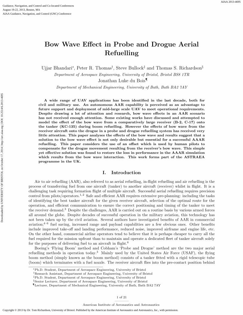
In a probe and drogue refuelling method, during the final stages of contact, the bow wave of the receiveraircraft is found to consistently push the drogue away from the probe as illustrated in figure 1. As a result,the pilot anticipates the movement of the drogue, rather than simply reacting to it. In this scenario, successor failure of the refuelling mission depends upon the pilot’s judgement, skill and experience in terms of thedrogue behaviour.
Different receiver aircraft will have different bow wave properties and the effect on the drogue is alsodependent on the probe position. Pilots are trained and expected to anticipate the movement of the droguefor the specific receiver type and aim for a point offset of the current drogue position whilst at the pre-contactposition. This offset is highly dependent on the bow wave dynamics of the receiver and the position of theprobe on the nose of the receiver. On a UAV, in the absence of a control system capable of anticipating the
3 of 21
American Institute of Aeronautics and Astronautics
Dow
nloa
ded
by U
NIV
ER
SIT
Y O
F B
RIS
TO
L o
n O
ctob
er 1
7, 2
014
| http
://ar
c.ai
aa.o
rg |
DO
I: 1
0.25
14/6
.201
3-46
95
NOT TO SCALE
Figure 1. Illustration of bow wave effect during the final contact stage in AAR.
Tanker Outer Loop
FCS
AAAR FCS
Supervisory
logic
Outer Loop
FCS
Disturbances
Hose and
Drogue
Inner Loop
FCS
Receiver A/C
Model
Receiver
Inner Loop
FCS
Tanker A/C
Model
Tanker
Visualisation
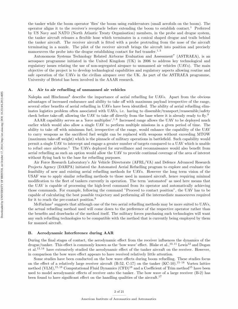
Figure 2. AAAR simulation environment.
movement of the drogue, it will only respond to the movement of the drogue. As a result, the UAV mightengage in drogue chasing, which will undoubtedly involve large control demands resulting in undesirableflight behaviour. Hence it is expected that some form of control authority which anticipates the movementof the drogue is required to predict the possible trajectory of the drogue within the final few meters beforecapture. This would also help to prevent the UAV or automated system in a manned aircraft from applyingexcessive control demands to track the drogue and improve capture performance.
III. Simulation Environment
A MATLAB20/SIMULINK21 (see figure 2) based simulation environment has been developed to simulatethe autonomous air to air refuelling procedure. The simulation environment is capable of simulating a fullaerial refuelling procedure starting from joining behind the tanker ending with breakaway from the formationfollowing refuelling. It contains a visualisation block which uses FlightGear22 (an open source flight simulator)to visualise the complete refuelling procedure using 3D models of the tanker, receiver and the probe anddrogue. This simulation environment has been extensively used in the AAAR research at the University ofBristol. A brief description of the simulation environment is provided here.
4 of 21
American Institute of Aeronautics and Astronautics
Dow
nloa
ded
by U
NIV
ER
SIT
Y O
F B
RIS
TO
L o
n O
ctob
er 1
7, 2
014
| http
://ar
c.ai
aa.o
rg |
DO
I: 1
0.25
14/6
.201
3-46
95
A. Aircraft Models
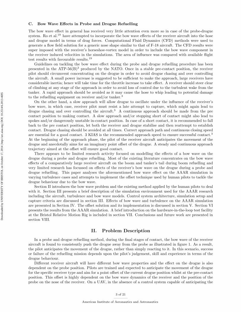
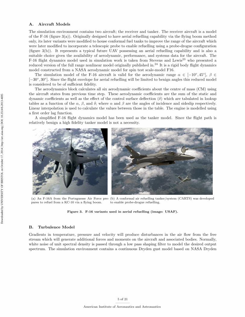
The simulation environment contains two aircraft; the receiver and tanker. The receiver aircraft is a modelof the F-16 (figure 3(a)). Originally designed to have aerial refuelling capability via the flying boom methodonly, its later variants were modified to house conformal fuel tanks to improve the range of the aircraft whichwere later modified to incorporate a telescopic probe to enable refuelling using a probe-drogue configuration(figure 3(b)). It represents a typical future UAV possessing an aerial refuelling capability and is also asuitable choice given the availability of aerodynamic, performance, and systems data for the aircraft. TheF-16 flight dynamics model used in simulation work is taken from Stevens and Lewis23 who presented areduced version of the full range nonlinear model originally published in.24 It is a rigid body flight dynamicsmodel constructed from a NASA aerodynamic model for spin test scale-model F16.
The simulation model of the F-16 aircraft is valid for the aerodynamic range α ∈ [−10◦, 45◦], β ∈[−30◦, 30◦]. Since the flight envelope for aerial refuelling will be limited to benign angles this reduced modelis considered to be of sufficient fidelity.
The aerodynamics block calculates all six aerodynamic coefficients about the centre of mass (CM) usingthe aircraft states from previous time step. These aerodynamic coefficients are the sum of the static anddynamic coefficients as well as the effect of the control surface deflection (δ) which are tabulated in lookuptables as a function of the α, β, and δ; where α and β are the angles of incidence and sideslip respectively.Linear interpolation is used to calculate the values between those in the table. The engine is modelled usinga first order lag function.
A simplified F-16 flight dynamics model has been used as the tanker model. Since the flight path isrelatively benign a high fidelity tanker model is not a necessity.
(a) An F-16A from the Portuguesse Air Force pre-pares to refuel from a KC-10 via a flying boom.
(b) A conformal air refuelling tanker/system (CARTS) was developedto enable probe-drogue refuelling.
Figure 3. F-16 variants used in aerial refuelling (image: USAF).
B. Turbulence Model
Gradients in temperature, pressure and velocity will produce disturbances in the air flow from the freestream which will generate additional forces and moments on the aircraft and associated bodies. Normally,white noise of unit spectral density is passed through a low pass shaping filter to model the desired outputspectrum. The simulation environment contains a continuous Dryden gust model based on NASA Dryden
5 of 21
American Institute of Aeronautics and Astronautics
Dow
nloa
ded
by U
NIV
ER
SIT
Y O
F B
RIS
TO
L o
n O
ctob
er 1
7, 2
014
| http
://ar
c.ai
aa.o
rg |
DO
I: 1
0.25
14/6
.201
3-46
95
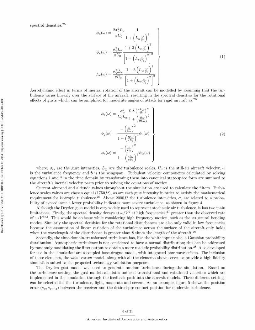
spectral densities:25
φu(ω) =2σ2
uLuπU0
1
1 +(Lu
ωU0
)2φv(ω) =
σ2vLvπU0
1 + 3(Lv
ωU0
)2[1 +
(Lv
ωU0
)2]2
φw(ω) =σ2wLwπU0
1 + 3(Lw
ωU0
)2[1 +
(Lw
ωU0
)2]2
(1)
Aerodynamic effect in terms of inertial rotation of the aircraft can be modelled by assuming that the tur-bulence varies linearly over the surface of the aircraft, resulting in the spectral densities for the rotationaleffects of gusts which, can be simplified for moderate angles of attack for rigid aircraft as:26
φp(ω) =σ2w
U0Lw
0.8(πLw
4b
) 13
1 +(
4bωπU0
)2φq(ω) =
−(ωU0
)21 +
(3bωπU0
)2φv(ω)
φr(ω) =−(ωU0
)21 +
(4bωπU0
)2φw(ω)
(2)
where, σ() are the gust intensities, L() are the turbulence scales, U0 is the still-air aircraft velocity, ωis the turbulence frequency and b is the wingspan. Turbulent velocity components calculated by solvingequations 1 and 2 in the time domain by transforming them into canonical state-space form are summed tothe aircraft’s inertial velocity parts prior to solving the equations of motion.
Current airspeed and altitude values throughout the simulation are used to calculate the filters. Turbu-lence scales values are chosen equal (1750ft), as are each gust intensity in order to satisfy the mathematicalrequirement for isotropic turbulence.25 Above 2000ft the turbulence intensities, σ, are related to a proba-bility of exceedance: a lower probability indicates more severe turbulence, as shown in figure 4.
Although the Dryden gust model is very widely used to represent stochastic air turbulence, it has two mainlimitations. Firstly, the spectral density decays at ω/V 2 at high frequencies,27 greater than the observed rateof ω/V 5/3. This would be an issue while considering high frequency motion, such as the structural bendingmodes. Similarly the spectral densities for the rotational disturbances are also only valid in low frequenciesbecause the assumption of linear variation of the turbulence across the surface of the aircraft only holdswhen the wavelength of the disturbance is greater than 8 times the length of the aircraft.26
Secondly, the time-domain-transformed turbulence has, like the white input noise, a Gaussian probabilitydistribution. Atmospheric turbulence is not considered to have a normal distribution; this can be addressedby randomly modulating the filter output to obtain a more realistic probability distribution.28 Also developedfor use in the simulation are a coupled hose-drogue model, with integrated bow wave effects. The inclusionof these elements, the wake vortex model, along with all the elements above serves to provide a high fidelitysimulation suited to the proposed technology validation purposes.
The Dryden gust model was used to generate random turbulence during the simulation. Based onthe turbulence setting, the gust model calculates induced translational and rotational velocities which areimplemented in the simulation through the feedback path into the aircraft models. Three different settingscan be selected for the turbulence, light, moderate and severe. As an example, figure 5 shows the positionerror (ex, ey, ez) between the receiver and the desired pre-contact position for moderate turbulence.
6 of 21
American Institute of Aeronautics and Astronautics
Dow
nloa
ded
by U
NIV
ER
SIT
Y O
F B
RIS
TO
L o
n O
ctob
er 1
7, 2
014
| http
://ar
c.ai
aa.o
rg |
DO
I: 1
0.25
14/6
.201
3-46
95

80
70
60
50
40
30
20
10
5 10 15 20 25RMS)Turbulence)Amplitude)σ (ft/s)TAS))
Alti
tude
)(th
ousa
nds)
of)f
eet)
Probability)of)Exceedance
10−2
10−3
10−4
Figure 4. Turbulence severity and exceedance probabilities.
posi
tion
erro
r
Figure 5. An example of the receiver holding position in moderate turbulence.
7 of 21
American Institute of Aeronautics and Astronautics
Dow
nloa
ded
by U
NIV
ER
SIT
Y O
F B
RIS
TO
L o
n O
ctob
er 1
7, 2
014
| http
://ar
c.ai
aa.o
rg |
DO
I: 1
0.25
14/6
.201
3-46
95
C. Control System Design
The supervisory logic (see figure 2) determines the stages in AAAR based on the current position of thereceiver relative to the tanker aircraft. The supervisory logic then generates waypoints for the receiverto follow in order to proceed with the refuelling procedure. The tanker controller is only responsible forgenerating the demands and control inputs for the tanker aircraft to follow the desired trajectory whetherit’s straight and level flight or flying a race track, etc., leaving the responsibility of refuelling solely on thereceiver aircraft’s FCS (Flight Control System), which generates the necessary demands and control inputsto manoeuvre the receiver through the various stages of refuelling. Each of the two aircraft has separate outerand inner loop controllers (see figure 2) responsible for generating demand and control input respectively.
As a typical refuelling flight condition, an airspeed and altitude combination of 200m/s and 8000m(≈26000ft) respectively was selected. The non linear F-16 aircraft model was linearised at this point. LinearQuadratic Regulator (LQR)23,29 method with full state feedback was applied to the linearised model in orderto generate the controller gains. The exact form of the LQR controller is not key here; the implementationof offset is the main feature of this application which is discused in section V.
D. Bow Wave Model
A bow wave model has been developed and integrated into the AAAR simulation environment. The modelproduces a static bow wave effect using the deflection of the hose in the flow around a Rankine aerodynamicflow model. The model is implemented as a lookup table of a function of its proximity to the receiver’s nose.The hose model consists of several lumped masses connected with linear springs with axial and bendingforces for each lumped mass. Rankine half body model has been used to generate the flow field in orderto obtain the forces on the lumped masses. Additionally, the aerodynamic forces resulting from the droguestructure and the shape of the hose itself are also included in the model.
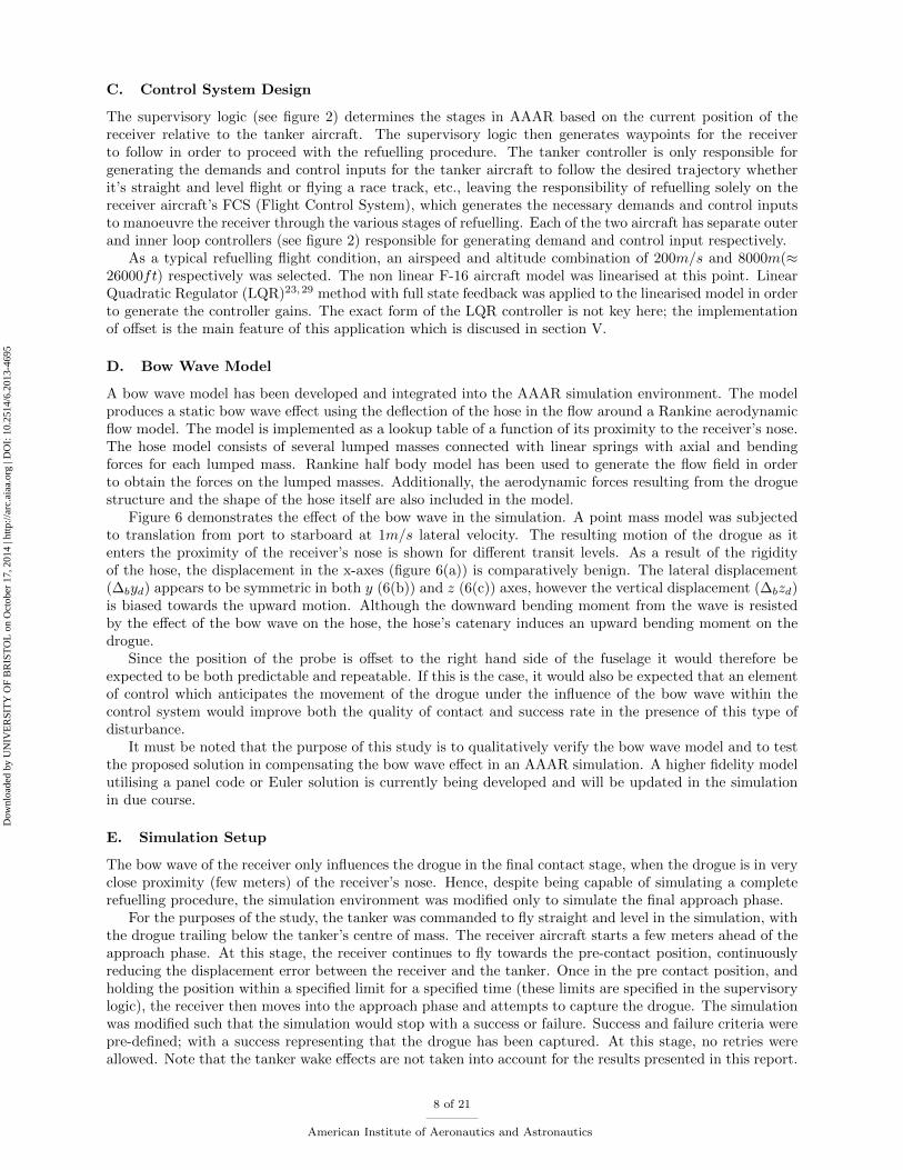
Figure 6 demonstrates the effect of the bow wave in the simulation. A point mass model was subjectedto translation from port to starboard at 1m/s lateral velocity. The resulting motion of the drogue as itenters the proximity of the receiver’s nose is shown for different transit levels. As a result of the rigidityof the hose, the displacement in the x-axes (figure 6(a)) is comparatively benign. The lateral displacement(∆byd) appears to be symmetric in both y (6(b)) and z (6(c)) axes, however the vertical displacement (∆bzd)is biased towards the upward motion. Although the downward bending moment from the wave is resistedby the effect of the bow wave on the hose, the hose’s catenary induces an upward bending moment on thedrogue.
Since the position of the probe is offset to the right hand side of the fuselage it would therefore beexpected to be both predictable and repeatable. If this is the case, it would also be expected that an elementof control which anticipates the movement of the drogue under the influence of the bow wave within thecontrol system would improve both the quality of contact and success rate in the presence of this type ofdisturbance.
It must be noted that the purpose of this study is to qualitatively verify the bow wave model and to testthe proposed solution in compensating the bow wave effect in an AAAR simulation. A higher fidelity modelutilising a panel code or Euler solution is currently being developed and will be updated in the simulationin due course.
E. Simulation Setup
The bow wave of the receiver only influences the drogue in the final contact stage, when the drogue is in veryclose proximity (few meters) of the receiver’s nose. Hence, despite being capable of simulating a completerefuelling procedure, the simulation environment was modified only to simulate the final approach phase.
For the purposes of the study, the tanker was commanded to fly straight and level in the simulation, withthe drogue trailing below the tanker’s centre of mass. The receiver aircraft starts a few meters ahead of theapproach phase. At this stage, the receiver continues to fly towards the pre-contact position, continuouslyreducing the displacement error between the receiver and the tanker. Once in the pre contact position, andholding the position within a specified limit for a specified time (these limits are specified in the supervisorylogic), the receiver then moves into the approach phase and attempts to capture the drogue. The simulationwas modified such that the simulation would stop with a success or failure. Success and failure criteria werepre-defined; with a success representing that the drogue has been captured. At this stage, no retries wereallowed. Note that the tanker wake effects are not taken into account for the results presented in this report.
8 of 21
American Institute of Aeronautics and Astronautics
Dow
nloa
ded
by U
NIV
ER
SIT
Y O
F B
RIS
TO
L o
n O
ctob
er 1
7, 2
014
| http
://ar
c.ai
aa.o
rg |
DO
I: 1
0.25
14/6
.201
3-46
95
(a)
(b)
(c)
Figure 6. Displacement of drogue from nominal position (∆x = ∆y = ∆z = 0) due to the bow wave from receiverduring transition from port to starboard. Axial separation is fixed at (∆x = 2m).
F. Capture and failure Logic
Figure 7 displays the capture zone used in the NASA AARD project.30 Taking a pilot’s recommendationinto account, the radius of the capture volume, Rc, was selected to be 4inches (0.1m), in order to achieve90% success rate with minimal vertical and lateral velocities. Hence in order to keep the probe within thecapture volume, very tight and accurate lateral and vertical control with accuracy within ±10cm is required.xcap defines a successful drogue capture in the longitudinal direction. A capture criteria similar to the NASAAARD project30 were defined. The point at which all the x, y and z errors, i.e. the longitudinal, lateral andvertical errors between the position of the probe and the drogue (e()dp) fell inside the capture volume wasused to define a successful capture.
Whilst tracking the error between the probe and the drogue, it was noticed that the relative approachspeed at the point of contact was close to 0m/s. As the error between the probe and the drogue approachedto 0, the FCS reduced the throttle demand, which means that the receiver arrives to the drogue with relativeapproach velocity close to 0. Although the simulation would define this situation as a successful capture,a relative closing speed of about 1 − 1.5m/s is required for a successful capture during actual refuellingscenario.3 In order to arrive at the drogue while maintaining a closing speed of about 1m/s, the FCS wascommanded to track a point few meters behind the drogue. Once the probe captures the drogue, this effectis removed.
Once the approach phase has started, the simulation would terminate either with a success or a failure- the receiver was not allowed to retreat and re-approach. Hence criteria were set up for the simulation toautomatically stop if the probe failed from entering the capture volume during the final approach phase.Three failure criteria were selected, firstly, the simulation would terminate if at any point in the approachphase, the probe went past the centre of the drogue but failed to satisfy the capture criteria as definedabove. Secondly, the simulation would stop if at any point the flight envelope of the model was exceeded.And lastly, the simulation would terminate if the receiver lost considerable altitude.
G. Capture and Failure Rates
In order to determine the capture and failure rates in the existing AAAR simulation, the simulation wasrun multiple times with random turbulence seeds. Random seeds were used in each simulation to introduce
9 of 21
American Institute of Aeronautics and Astronautics
Dow
nloa
ded
by U
NIV
ER
SIT
Y O
F B
RIS
TO
L o
n O
ctob
er 1
7, 2
014
| http
://ar
c.ai
aa.o
rg |
DO
I: 1
0.25
14/6
.201
3-46
95

Figure 7. The probe miss and capture zones employed in the NASA AARD project.30
a random element within the simulation. A set of multiple random seeds with 6 elements in each weregenerated. A single set of random seeds was used for each of the run sets in order to be able to provide afair comparison.
IV. Initial Simulation Results
Initial simulation results were analysed to determine the effect of the bow wave on the AAAR simulation.Furthermore, the effect of turbulence on the simulation was also analysed.
A. Effect of bow wave on the simulation
The bow wave of the receiver is expected to push the drogue away from the nose of the receiver as it entersthe vicinity of the bow wave formed around the receiver’s nose. As the drogue moves, restoring force on thedrogue due to its weight and the effects of the hose dynamics due to hose’s catenary, will prevent the droguefrom drifting linearly under the influence of the receiver’s bow wave. As a result of the receiver approachingthe drogue, the drogue initially starts to move away from the receiver, the restoring force on the drogue alsoincreases. After a certain point, the restoring force on the drogue compensates for the force due to the bowwave effect and the displacement of the drogue will appear to reduce.
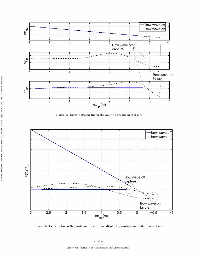
AAAR was simulated with and without the bow wave effects in still air. The bow wave was expectedto displace the drogue away from the receiver’s trajectory. In absence of controller compensation in theAAAR FCS, the simulation was expected to fail to capture the drogue in presence of the bow wave effects.In presence of the bow wave, as the drogue moves, the error between the probe and the drogue was expectedto rise, despite reacting to the error, the control system was expected to fail to capture the drogue.
Figures 8 and 9 compare the bow wave effect on the AAAR simulation while in the capture phase.Error in the distances between the probe and the drogue in all three axes is compared in figure 8, as thelongitudinal distance between the probe and the drogue reduces. Initially the errors appear to increase asthe probe closes on the drogue, which is expected. The error in x appears to be small compared to that iny and z (see figure 6 as well), despite the effect of the bow wave, the controller compensates for the errorand large deviations are not seen. However errors in y and z are significant and have adverse effect on theAAAR process, ultimately resulting in failure to capture in this case as expected. Successful capture (solidcurves) in absence of the bow wave and the receiver failing to capture the drogue in presence of the bowwave (dashed curves) can be seen in figures 8 and 9.
10 of 21
American Institute of Aeronautics and Astronautics
Dow
nloa
ded
by U
NIV
ER
SIT
Y O
F B
RIS
TO
L o
n O
ctob
er 1
7, 2
014
| http
://ar
c.ai
aa.o
rg |
DO
I: 1
0.25
14/6
.201
3-46
95
−10123456
exdp
−10123456
ezdp
exdp
(m)
Bow wave offBow wave on
−10123456
eydp
Bow wave offcapture
Bow wave onfailure
Figure 8. Error between the probe and the drogue in still air.
−1−0.500.511.522.53
e(x,
y,z)
dp
exdp
(m)
bow wave offbow wave on
Bow wave offcapture
Bow wave onfailure
Figure 9. Error between the probe and the drogue displaying capture and failure in still air.
11 of 21
American Institute of Aeronautics and Astronautics
Dow
nloa
ded
by U
NIV
ER
SIT
Y O
F B
RIS
TO
L o
n O
ctob
er 1
7, 2
014
| http
://ar
c.ai
aa.o
rg |
DO
I: 1
0.25
14/6
.201
3-46
95
B. Effect of turbulence on the simulation
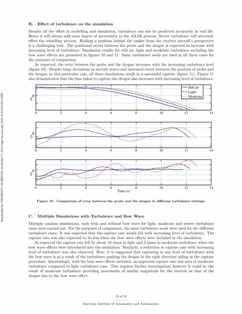
Despite all the effort in modelling and simulation, turbulence can not be predicted accurately in real life.Hence it will always add some degree of uncertainty to the AAAR process. Severe turbulence will adverselyeffect the refuelling process. Holding a position behind the tanker from the receiver aircraft’s perspectiveis a challenging task. The positional errors between the probe and the drogue is expected to increase withincreasing level of turbulence. Simulation results for still air, light and moderate turbulence excluding thebow wave effects are presented in figures 10 and 11. Same turbulence seeds are used in all three cases forthe purposes of comparison.
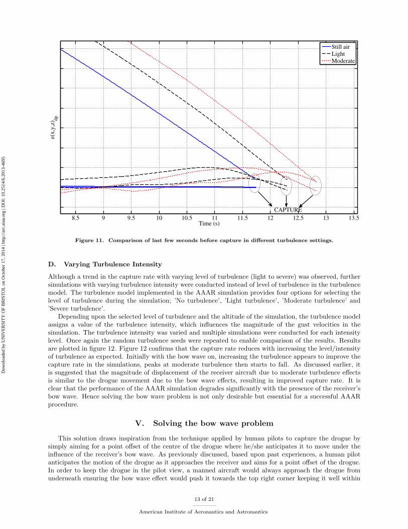
As expected, the error between the probe and the drogue increases with the increasing turbulence level(figure 10). Despite large deviations in aircraft states and increased errors between the position of probe andthe drogue, in this particular case, all three simulations result in a successful capture (figure 11). Figure 11also demonstrates that the time taken to capture the drogue also increases with increasing level of turbulence.
0 2 4 6 8 10 12 14
exdp
0 2 4 6 8 10 12 14
eydp
0 2 4 6 8 10 12 14
ezdp
Time (s)
Still air
Light
Moderate
Figure 10. Comparison of error between the probe and the drogue in different turbulence settings.
C. Multiple Simulations with Turbulence and Bow Wave
Multiple random simulations, each with and without bow wave for light, moderate and severe turbulencecases were carried out. For the purposes of comparison, the same turbulence seeds were used for the differentturbulence cases. It was expected that the capture rate would fall with increasing level of turbulence. Thecapture rate was also expected to be less when the bow wave effects were included in the simulation.
As expected the capture rate fell by about 10 times in light and 3 times in moderate turbulence when thebow wave effects were introduced into the simulation. Similarly, a reduction in capture rate with increasinglevel of turbulence was also observed. Here, it is suggested that capturing in any level of turbulence withthe bow wave is as a result of the turbulence pushing the drogue in the right direction aiding in the captureprocedure. Interestingly, with the bow wave effects included, an improved capture rate was seen at moderateturbulence compared to light turbulence case. This requires further investigation; however it could be theresult of moderate turbulence providing movements of similar magnitude for the receiver as that of thedrogue due to the bow wave effect.
12 of 21
American Institute of Aeronautics and Astronautics
Dow
nloa
ded
by U
NIV
ER
SIT
Y O
F B
RIS
TO
L o
n O
ctob
er 1
7, 2
014
| http
://ar
c.ai
aa.o
rg |
DO
I: 1
0.25
14/6
.201
3-46
95
8.5 9 9.5 10 10.5 11 11.5 12 12.5 13 13.5
e(x,y
,z) d
p
Time (s)
Still air
Light
Moderate
CAPTURE
Figure 11. Comparison of last few seconds before capture in different turbulence settings.
D. Varying Turbulence Intensity
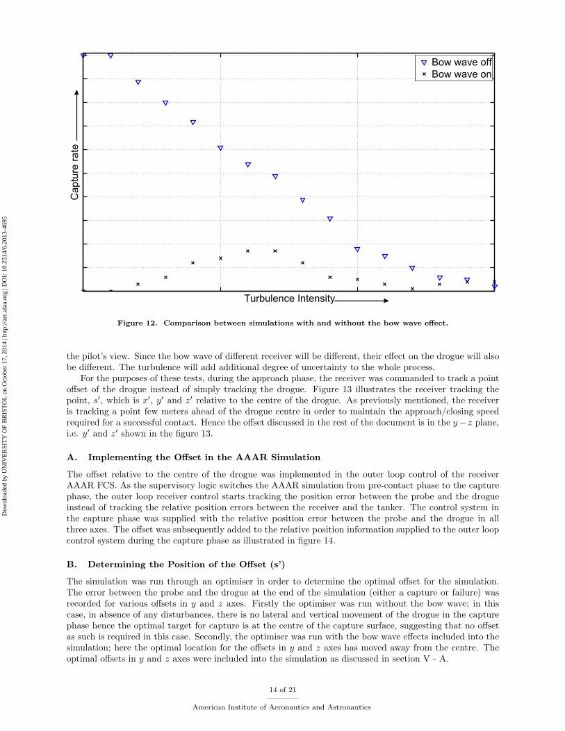
Although a trend in the capture rate with varying level of turbulence (light to severe) was observed, furthersimulations with varying turbulence intensity were conducted instead of level of turbulence in the turbulencemodel. The turbulence model implemented in the AAAR simulation provides four options for selecting thelevel of turbulence during the simulation; ’No turbulence’, ’Light turbulence’, ’Moderate turbulence’ and’Severe turbulence’.
Depending upon the selected level of turbulence and the altitude of the simulation, the turbulence modelassigns a value of the turbulence intensity, which influences the magnitude of the gust velocities in thesimulation. The turbulence intensity was varied and multiple simulations were conducted for each intensitylevel. Once again the random turbulence seeds were repeated to enable comparison of the results. Resultsare plotted in figure 12. Figure 12 confirms that the capture rate reduces with increasing the level/intensityof turbulence as expected. Initially with the bow wave on, increasing the turbulence appears to improve thecapture rate in the simulations, peaks at moderate turbulence then starts to fall. As discussed earlier, itis suggested that the magnitude of displacement of the receiver aircraft due to moderate turbulence effectsis similar to the drogue movement due to the bow wave effects, resulting in improved capture rate. It isclear that the performance of the AAAR simulation degrades significantly with the presence of the receiver’sbow wave. Hence solving the bow wave problem is not only desirable but essential for a successful AAARprocedure.
V. Solving the bow wave problem
This solution draws inspiration from the technique applied by human pilots to capture the drogue bysimply aiming for a point offset of the centre of the drogue where he/she anticipates it to move under theinfluence of the receiver’s bow wave. As previously discussed, based upon past experiences, a human pilotanticipates the motion of the drogue as it approaches the receiver and aims for a point offset of the drogue.In order to keep the drogue in the pilot view, a manned aircraft would always approach the drogue fromunderneath ensuring the bow wave effect would push it towards the top right corner keeping it well within
13 of 21
American Institute of Aeronautics and Astronautics
Dow
nloa
ded
by U
NIV
ER
SIT
Y O
F B
RIS
TO
L o
n O
ctob
er 1
7, 2
014
| http
://ar
c.ai
aa.o
rg |
DO
I: 1
0.25
14/6
.201
3-46
95
Turbulence Intensity
Cap
ture
rat
eBow wave offBow wave on
Figure 12. Comparison between simulations with and without the bow wave effect.
the pilot’s view. Since the bow wave of different receiver will be different, their effect on the drogue will alsobe different. The turbulence will add additional degree of uncertainty to the whole process.
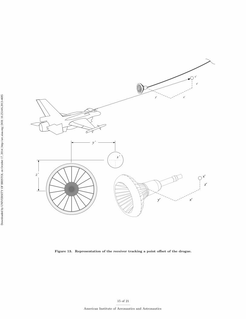
For the purposes of these tests, during the approach phase, the receiver was commanded to track a pointoffset of the drogue instead of simply tracking the drogue. Figure 13 illustrates the receiver tracking thepoint, s′, which is x′, y′ and z′ relative to the centre of the drogue. As previously mentioned, the receiveris tracking a point few meters ahead of the drogue centre in order to maintain the approach/closing speedrequired for a successful contact. Hence the offset discussed in the rest of the document is in the y− z plane,i.e. y′ and z′ shown in the figure 13.
A. Implementing the Offset in the AAAR Simulation
The offset relative to the centre of the drogue was implemented in the outer loop control of the receiverAAAR FCS. As the supervisory logic switches the AAAR simulation from pre-contact phase to the capturephase, the outer loop receiver control starts tracking the position error between the probe and the drogueinstead of tracking the relative position errors between the receiver and the tanker. The control system inthe capture phase was supplied with the relative position error between the probe and the drogue in allthree axes. The offset was subsequently added to the relative position information supplied to the outer loopcontrol system during the capture phase as illustrated in figure 14.
B. Determining the Position of the Offset (s’)
The simulation was run through an optimiser in order to determine the optimal offset for the simulation.The error between the probe and the drogue at the end of the simulation (either a capture or failure) wasrecorded for various offsets in y and z axes. Firstly the optimiser was run without the bow wave; in thiscase, in absence of any disturbances, there is no lateral and vertical movement of the drogue in the capturephase hence the optimal target for capture is at the centre of the capture surface, suggesting that no offsetas such is required in this case. Secondly, the optimiser was run with the bow wave effects included into thesimulation; here the optimal location for the offsets in y and z axes has moved away from the centre. Theoptimal offsets in y and z axes were included into the simulation as discussed in section V - A.
14 of 21
American Institute of Aeronautics and Astronautics
Dow
nloa
ded
by U
NIV
ER
SIT
Y O
F B
RIS
TO
L o
n O
ctob
er 1
7, 2
014
| http
://ar
c.ai
aa.o
rg |
DO
I: 1
0.25
14/6
.201
3-46
95
s′
x′y′
z′
y’
z’
s’
s′
x′y′
z′
Figure 13. Representation of the receiver tracking a point offset of the drogue.
15 of 21
American Institute of Aeronautics and Astronautics
Dow
nloa
ded
by U
NIV
ER
SIT
Y O
F B
RIS
TO
L o
n O
ctob
er 1
7, 2
014
| http
://ar
c.ai
aa.o
rg |
DO
I: 1
0.25
14/6
.201
3-46
95
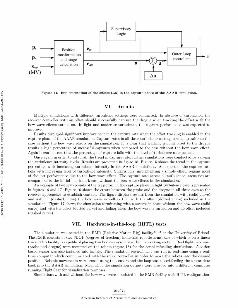
Figure 14. Implementation of the offsets (∆a) in the capture phase of the AAAR simulation.
VI. Results
Multiple simulations with different turbulence settings were conducted. In absence of turbulence, thereceiver controller with an offset should successfully capture the drogue when tracking the offset with thebow wave effects turned on. In light and moderate turbulence, the capture performance was expected toimprove.
Results displayed significant improvement in the capture rate when the offset tracking is enabled in thecapture phase of the AAAR simulation. Capture rates in all three turbulence settings are comparable to thecase without the bow wave effects on the simulation. It is clear that tracking a point offset to the drogueresults a high percentage of successful captures when compared to the case without the bow wave effect.Again it can be seen that the percentage of capture falls with the level of turbulence as expected.
Once again in order to establish the trend in capture rate, further simulations were conducted by varyingthe turbulence intensity levels. Results are presented in figure 15. Figure 15 shows the trend in the capturepercentage with increasing turbulence intensity in the AAAR simulations. As expected, the capture ratefalls with increasing level of turbulence intensity. Surprisingly, implementing a simple offset, regains mostof the lost performance due to the bow wave effect. The capture rate across all turbulence intensities arecomparable to the initial benchmark case without the bow wave effects in the simulation.
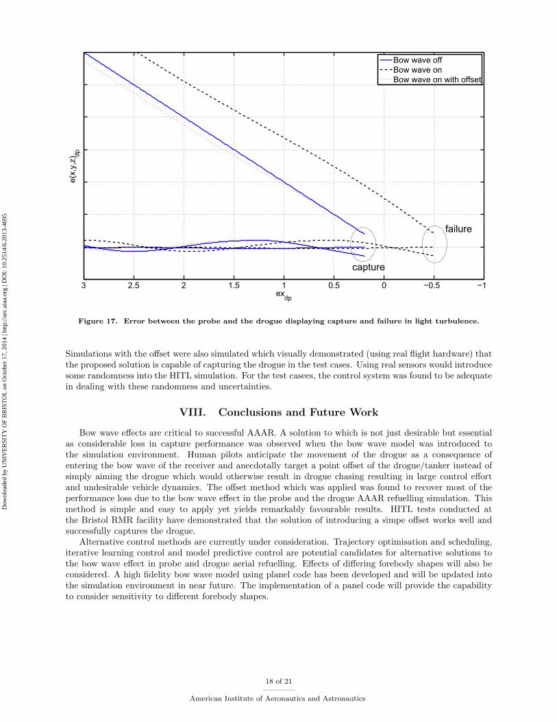
An example of last few seconds of the trajectory in the capture phase in light turbulence case is presentedin figures 16 and 17. Figure 16 shows the errors between the probe and the drogue in all three axes as thereceiver approaches to establish contact. The figure displays results from the simulation with (solid curve)and without (dashed curve) the bow wave as well as that with the offset (dotted curve) included in thesimulation. Figure 17 shows the simulation terminating with a success in cases without the bow wave (solidcurve) and with the offset (dotted curve) and failing when the bow wave is turned on and no offset included(dashed curve).
VII. Hardware-in-the-loop (HITL) tests
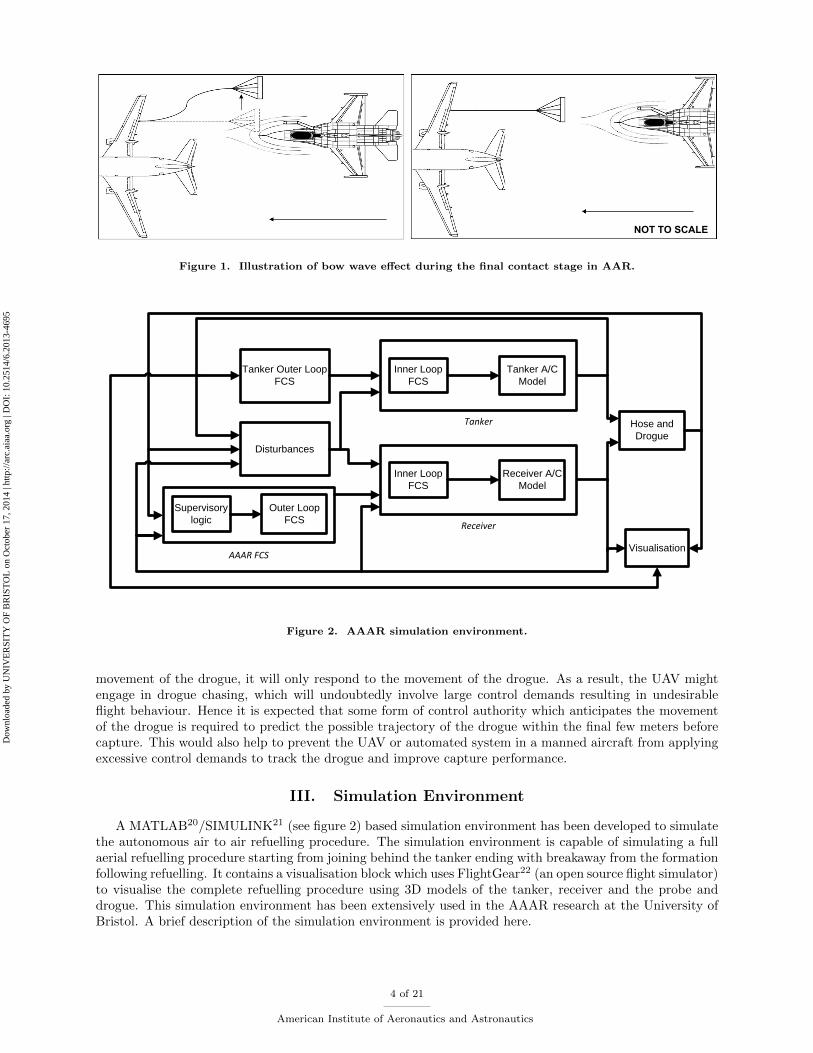
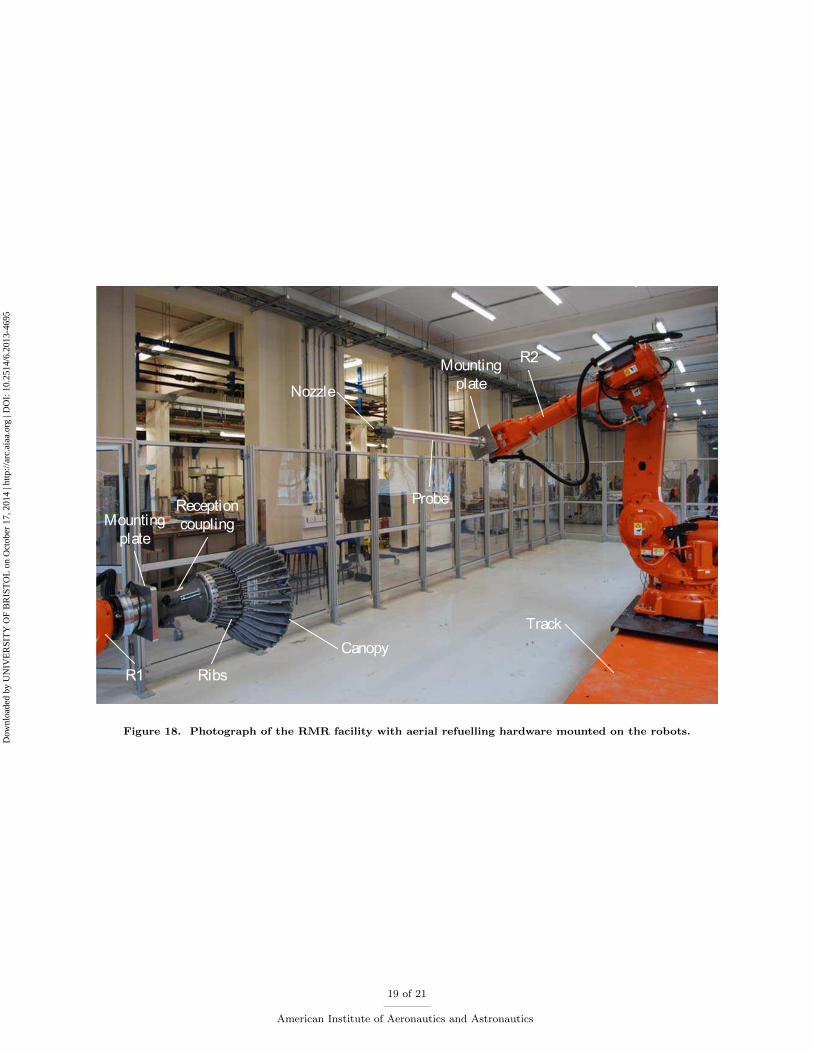
The simulation was tested in the RMR (Relative Motion Rig) facility31,32 at the University of Bristol.The RMR consists of two 6DOF (degrees of freedom) industrial robotic arms; one of which is on a lineartrack. This facility is capable of placing two bodies anywhere within its working section. Real flight hardware(probe and drogue) were mounted on the robots (figure 18) for the aerial refuelling simulations. A visionbased sensor was also installed into facility. The simulation environment was run in real-time using a real-time computer which communicated with the robot controller in order to move the robots into the desiredposition. Robotic movements were sensed using the sensors and the loop was closed feeding the sensor databack into the AAAR simulation. Meanwhile the simulation outputs were also fed into a different computerrunning FlightGear for visualisation purposes.
Simulations with and without the bow wave were simulated in the RMR facility with HITL configuration.
16 of 21
American Institute of Aeronautics and Astronautics
Dow
nloa
ded
by U
NIV
ER
SIT
Y O
F B
RIS
TO
L o
n O
ctob
er 1
7, 2
014
| http
://ar
c.ai
aa.o
rg |
DO
I: 1
0.25
14/6
.201
3-46
95

Turbulence Intensity
Cap
ture
rat
eBow wave offBow wave onBow wave on with offset
Figure 15. Comparison of the results from simulations tracking an offset with previous simulations with andwithout the wave at varying turbulence intensities.
−10123456
exdp
Bow wave offBow wave onBow wave on with offset
−10123456
eydp
−10123456
ezdp
exdp
capture
failure
Figure 16. Comparison of error between the probe and the drogue in light turbulence.
17 of 21
American Institute of Aeronautics and Astronautics
Dow
nloa
ded
by U
NIV
ER
SIT
Y O
F B
RIS
TO
L o
n O
ctob
er 1
7, 2
014
| http
://ar
c.ai
aa.o
rg |
DO
I: 1
0.25
14/6
.201
3-46
95
−1−0.500.511.522.53ex
dp
e(x,
y,z)
dp
Bow wave offBow wave onBow wave on with offset
capture
failure
Figure 17. Error between the probe and the drogue displaying capture and failure in light turbulence.
Simulations with the offset were also simulated which visually demonstrated (using real flight hardware) thatthe proposed solution is capable of capturing the drogue in the test cases. Using real sensors would introducesome randomness into the HITL simulation. For the test casees, the control system was found to be adequatein dealing with these randomness and uncertainties.
VIII. Conclusions and Future Work
Bow wave effects are critical to successful AAAR. A solution to which is not just desirable but essentialas considerable loss in capture performance was observed when the bow wave model was introduced tothe simulation environment. Human pilots anticipate the movement of the drogue as a consequence ofentering the bow wave of the receiver and anecdotally target a point offset of the drogue/tanker instead ofsimply aiming the drogue which would otherwise result in drogue chasing resulting in large control effortand undesirable vehicle dynamics. The offset method which was applied was found to recover most of theperformance loss due to the bow wave effect in the probe and the drogue AAAR refuelling simulation. Thismethod is simple and easy to apply yet yields remarkably favourable results. HITL tests conducted atthe Bristol RMR facility have demonstrated that the solution of introducing a simpe offset works well andsuccessfully captures the drogue.
Alternative control methods are currently under consideration. Trajectory optimisation and scheduling,iterative learning control and model predictive control are potential candidates for alternative solutions tothe bow wave effect in probe and drogue aerial refuelling. Effects of differing forebody shapes will also beconsidered. A high fidelity bow wave model using planel code has been developed and will be updated intothe simulation environment in near future. The implementation of a panel code will provide the capabilityto consider sensitivity to different forebody shapes.
18 of 21
American Institute of Aeronautics and Astronautics
Dow
nloa
ded
by U
NIV
ER
SIT
Y O
F B
RIS
TO
L o
n O
ctob
er 1
7, 2
014
| http
://ar
c.ai
aa.o
rg |
DO
I: 1
0.25
14/6
.201
3-46
95
Reception coupling
Canopy
RibsR1
Mounting plate
R2
Nozzle
Probe
Mounting plate
Track
Figure 18. Photograph of the RMR facility with aerial refuelling hardware mounted on the robots.
19 of 21
American Institute of Aeronautics and Astronautics
Dow
nloa
ded
by U
NIV
ER
SIT
Y O
F B
RIS
TO
L o
n O
ctob
er 1
7, 2
014
| http
://ar
c.ai
aa.o
rg |
DO
I: 1
0.25
14/6
.201
3-46
95
Acknowledgements
This work is funded by Cobham Mission Equipment as part of the ASTRAEA Programme. The AS-TRAEA programme is co-funded by AOS, BAE Systems, Cobham, EADS Cassidian, QinetiQ, Rolls-Royce,Thales, the Technology Strategy Board, the Welsh Assembly Government and Scottish Enterprise. Website:http://www.astraea.aero/.
References
1Mcfarlane, C., An Investigation of Flying Qualities for Fixed Wing Unmanned Aerial Vehicles, Ph.d. thesis, Universityof Bristol, 2009.
2Dogan, A., Sato, S., and Blake, W., “Flight Control and Simulation for Aerial Refueling,” AIAA Guidance, Navigationand Control Conference and Exhibit, San Francisco, California, August 2005.
3NATO, “ATP-56(B) Air-to-Air Refuelling,” Tech. rep., NATO, 2010.4Nangia, R. K., “Operations and aircraft design towards greener civil aviation using air-to-air refuelling,” The Aeronautical
Journal , November 2006.5Nangia, R. K., “’Greener’ civil aviation using air-to-air refuelling - relating aircraft design efficiency and tanker offload
efficiency,” The Aeronautical Journal , September 2007.6Bennington, M., “Aerial Refueling Implications for Commercial Aviation,” Journal of Aircraft , Vol. 42, No. 2, March-
April 2005, pp. 366–375.7“Autonomous Systems Technology Related Airborne Evaluation & Assessment (ASTRAEA),” http://www.astraea.aero/.8Nalepka, J. P. and Hinchman, J. L., “Automated Aerial Refueling : Extending the Effectiveness of Unmanned Air
Vehicles,” AIAA Modeling and Simulation Technologies Conference and Exhibit, San Francisco, California, August 2005.9Burns, R. S., Clark, C. S., and Ewart, R., “The Automated Aerial Refueling Simulation at the AVTAS Laboratory,”
AIAA Modeling and Simulation Technologies Conference and Exhibit, San Francisco, California, August 2005.10Blake, W. B. and Dickes, E. G., “UAV Aerial Refueling-Wind Tunnel Results and Conparison with Analytical Predic-
tions,” Tech. Rep. AFRL-VA-WP-TP-2004-300, Air Vehicles Directorate, Air Force Research Labarotary, Air Force MaterialCommand, Wright-Patterson Air Force Base, January 2004.
11Blake, W., Dickes, E. G., and Gingras, D. R., “UAV Aerial Refueling - Wind Tunnel Results and Comparison withAnalytical Predictions,” AIAA Atmospheric Flight Mechanics Conference and Exhibit, Providence, Rhode Island, August2004.
12Lewis, T. A., Flight Data Analysis and Simulation of Wind Effects During Aerial Refueling, Ph.D. thesis, The Universityof Texas at Arlington, November 2008.
13Dogan, A., Lewis, T. A., and Blake, W., “Wake-Vortex Induced Wind with Turbulence in Aerial Refueling - Part A :Flight Data Analysis,” AIAA Atmospheric Flight Mechanics Conference and Exhibit, Honolulu, Hawaii, August 2008.
14Dogan, A., Lewis, T. a., and Blake, W., “Flight Data Analysis and Simulation of Wind Effects During Aerial Refueling,”Journal of Aircraft , Vol. 45, No. 6, November 2008.
15Eric H. Hoganson, A Study of the Aerodynamic Interference Effects During Aerial Refueling, Ph.D. thesis, Air University,Wright-Patterson Air Force Base, 1983.
16III, G. W. R. and Platz, S. J., “Developing Aerial Refueling Simulation Models from Flight Test Data using AlternativePID Methods,” RTO SCI Symposium on ”System Identification for Integrated Aircraft Development and Flight Testing”,Madrid, Spain, May 1998.
17Dogan, A. and Blake, W., “Modeling of Bow Wave Effect in Aerial Refueling,” AIAA Atmospheric Flight MechanicsConference, Toronto, Ontario Canada, August 2010.
18Haag, C., Schwaab, M., and Blake, W., “Computational Analysis of the Bow Wave Effect in Air-to-Air Refueling,” AIAAAtmospheric Flight Mechanics Conference, Toronto, Ontario Canada, August 2010.
19Ro, K., Kuk, T., and Kamman, J. W., “Active Control of Aerial Refueling Hose-Drogue Systems,” AIAA Guidance,Navigation, and Control Conference, Toronto, Ontario Canada, August 2010.
20“MATLAB,” http://www.mathworks.co.uk/products/matlab/.21“SIMULINK,” http://www.mathworks.co.uk/products/simulink/.22“FlightGear,” http://www.flightgear.org/.23Stevens, B. L. and Lewis, F. L., Aircraft Control and Simulation, John Wiley & Sons, USA, 2nd ed., 2003.24Nguyen, L. T., Ogburn, M. E., Gilbert, W. P., Kibler, K. S., Brow, P. W., and Deal, P. L., “Simulator Study of Stall
Characteristics of a Fighter Airplane with Relaxed Longitudinal Static Stability,” Tech. rep., NASA, December 1979.25MIL-F-8785C, “Flying Qualities of Piloted Aircraft,” Tech. rep., Department of Defence, USA, 1980.26Roskam, J., Airplane Flight Dynamics and Automatic Flight Controls, Roskam Aviation and engineering Corporation,
1979.27Wang, S.-T. and Frost, W., “Atmospheric Turbulence Simulation Techniques With Application to Flight Analysis,” Tech.
rep., NASA, 1980.28Justus, C. G., Campbell, C. W., Doubleday, M. K., and Johnson, D. L., “New Atmospheric Turbulence Model for Shuttle
Applications,” Tech. rep., NASA, 1990.29Bryson, A. E. and Ho, Y.-C., Applied Optimal Control , Ginn and Company, 1969.30Dibley, R. P., Allen, M. J., and Nabaa, N., “Autonomous Airborne Refueling Demonstration , Phase I Flight-Test
Results,” Tech. rep., NASA Dryden Flight Research Center, Edwards California, December 2007.
20 of 21
American Institute of Aeronautics and Astronautics
Dow
nloa
ded
by U
NIV
ER
SIT
Y O
F B
RIS
TO
L o
n O
ctob
er 1
7, 2
014
| http
://ar
c.ai
aa.o
rg |
DO
I: 1
0.25
14/6
.201
3-46
95

31du Bois, J. L., Thomas, P. R., and Richardson, T. S., “Development of a Relative Motion Facility for Simulations ofAutonomous Air to Ait Refuelling,” IEEE Aerospace Conference, US, March 2012.
32du Bois, J. L., Thomas, P., Bullock, S., Bhandari, U., and Richardson, T. S., “Control Methodologies for Relative MotionReproduction in a Robotic Hybrid Test Simulation of Aerial Refuelling,” AIAA Guidance, Navigation, and Control Conference,Minneapolis, Minnesota, August 2012.
21 of 21
American Institute of Aeronautics and Astronautics
Dow
nloa
ded
by U
NIV
ER
SIT
Y O
F B
RIS
TO
L o
n O
ctob
er 1
7, 2
014
| http
://ar
c.ai
aa.o
rg |
DO
I: 1
0.25
14/6
.201
3-46
95